Article

Enabling LPWANs for Coexistence and Diverse IoT Applications in Smart Cities Using Lightweight Heterogenous Multihomed Network Model

by
Emmanuel Utochukwu Ogbodo
1,*,
Adnan M. Abu-Mahfouz
1,2 and
Anish M. Kurien
1
1
Department of Electrical Engineering, Tshwane University of Technology, Pretoria 0001, South Africa
2
Council for Scientific and Industrial Research (CSIR), Pretoria 0001, South Africa
*
Author to whom correspondence should be addressed.
J. Sens. Actuator Netw. 2022, 11(4), 87; https://doi.org/10.3390/jsan11040087
Submission received: 11 November 2022 / Revised: 7 December 2022 / Accepted: 13 December 2022 / Published: 19 December 2022
(This article belongs to the Section Big Data, Computing and Artificial Intelligence)

Abstract

:
Smart cities have been envisioned to provide smartness in managing internet of things (IoT) application domains, such as transport and mobility, health care, natural resources, electricity and energy, homes and buildings, commerce and retail, society and workplace, industry, agriculture, and the environment. The growth trajectory in usage of these IoT domains has led to a heterogeneous dense network in a smart city environment. The heterogeneous dense network in smart cities has led to challenges, such as difficulties in the management of LPWAN coexistence, interference, spectrum insufficiency, QoS, and scalability issues. The existing LPWAN technologies cannot support the heterogeneous dense network challenges in smart cities. Further, it cannot support diverse IoT, including medium- to high-bandwidth applications, due to the power, complexity, and resource constraints of the LPWAN devices. Hence, this paper addresses high data rate IoT applications and heterogeneous dense networks. This paper proposes a lightweight heterogenous multihomed network (LHM-N) model for diverse smart city applications that will address dense heterogeneity network challenges in a smart city. The work aims to advocate and integrate a manageable license-free LPWAN that will coexist with 5G private and public cellular networks in the LHM-N model. This will help to provide a cost-effective solution model in a heterogeneous dense smart city environment. Further, a secured lightweight energy-efficient packet-size forwarding engine (PSFE) algorithm is presented using the discrete event simulation (DES) methodological approach in MATLAB for complexity evaluation. In addition, a 5G reduced capability (RedCap) IoT device is integrated into the (LHM-N) model to support smart city. Finally, the results show that the LHM-N model outperforms the conventional quadrature amplitude modulation (QAM) protocol scheme in terms of error rate, latency, and data throughput with reduced energy costs for medium- to high-bandwidth industrial IoT applications. This validates the suitability of the LHM-N model for high data rate IoT applications.

1. Introduction

A low-power wide area network (LPWAN) is a communication means for applications that require low data rate, low power, and low cost over a long range. The Internet of Things (IoT) is a typical example of such an application. There are numerous LPWAN technologies. However, the predominant ones are LoRaWAN, Sigfox, LTE-M (long-term evolution for machine-type communication (MTC)) enhanced MTC, and NB-IoT (Narrowband IoT). These technologies have significantly impacted numerous IoT deployment use cases, especially in the smart cities ecosystem. Smart cities have been envisaged to provide smartness in managing domains, such as transport and mobility, health care, natural resources, electricity and energy, homes and buildings, commerce and retail, society and workplace, industry, agriculture, and the environment. The use cases of these domains have led to a heterogeneous dense network in a smart city environment. Supporting massively connected devices requires very low-cost end users devices, such as LPWANs [1,2,3].
Several LPWANs meant to satisfy diverse IoT application domains can be attributed to this dense heterogeneity in a smart city. Heterogeneity is inherent in IoT communications due to the vast range of hardware and software capabilities [4]. LPWANs are considered preferred technologies for diverse IoT connectivity compared to short-range communication technologies, such as Bluetooth, ZigBee, and Wi-Fi, due to their unique characteristics [5]. However, high-bandwidth smart city applications, such as industrial wireless sensors (smart manufacturing/smart factory), smart wearabl, and video surveillance, are not supported by LPWAN. Consequently, the third-generation partnership project (3GPP) has finalized the specification for the 5G reduced capability (RedCap) device, which was recently published in the latest 3GPP release-17 [6]. This will support medium to high-speed connections for bandwidth-demanding smart city applications. Hence, RedCap devices can be positioned as a lower segment than eMBB (enhanced mobile broadband) devices with little variation in complexity and coverage distance compared to LPWAN devices. This means that it has more complexity with lesser coverage than the LPWAN by achieving a balance between network performance (high bandwidth and low latency) and device costs. Nevertheless, the reduced coverage can be compensated by considering smaller data rate specifications. This will help to improve coverage distance for the NR RedCap [7]. Further, the device protocol enhancement can achieve a reduction in complexity. Therefore, 5G RedCap could be considered as LPWAN-MHS (medium-high speed), i.e., an LPWAN with medium to high-speed applications support based on the specification for improved distance and low power.
Moreover, other challenges exist, such as coexistence, interference, spectrum insufficiency, and scalability issues, due to this heterogeneity densification. These problems can affect the quality of service (QoS) requirements of IoT applications, including performance degradation of LPWAN devices. Several methods have been advocated to address these problems. For instance, in addressing the problems of interference and spectrum insufficiency, the authors in [8] suggested that spectrum allocation can be moved from the 2.4 GHz band to a license-free spectrum in the sub-1 GHz free band. However, as the use cases increase in the sub-1 GHz band due to IoT network densification, this band will face comparable interference issues to the 2.4 GHz band. Further, the use of multi-radio access technology (multihoming) integration has been suggested in [9] in dealing with the problems of coexistence and scalability issues. Consequently, to circumvent the identified problems, this paper proposes a lightweight heterogenous network model for enabling LPWANs’ coexistence and diverse IoT applications in a heterogenous dense smart city’s IoT network. Hence, to actualize this, the following objectives are enumerated:
  • To integrate a manageable license-free LPWAN that will coexist with 5G private and public cellular networks.
  • To develop an LHM-N model for enabling the coexistence of different LPWANs.
  • To provide a very cost-effective solution model in a heterogeneous dense smart city environment.
  • To develop a secured, lightweight, energy-efficient packet-size forwarding engine (PSFE) algorithm.
To this end, the original contributions of this paper include:
  • Proposing a model with a low error rate that improves the data throughput by a magnitude of over five times more than the conventional quadrature amplitude modulation (QAM) protocol scheme with reduced energy cost for medium- to high-bandwidth industrial IoT (IIoT) applications.
  • Optimizing the Physical (PHY) layer protocol of 5G reduced capability (RedCap) IoT devices to operate comparatively with LPWAN in terms of signal-to-noise ratio (SNR) symbol energy while maintaining medium to high data throughput.
  • Designing and implementing a lightweight heterogenous multihomed network (LHM-N) model for diverse smart city applications.
  • Advocating and incorporating a manageable license-free LPWAN coexistence with 5G private and public cellular networks to provide a very cost-effective solution model in a heterogeneous dense smart city environment.
  • Proposing a packet-size forwarding engine (PSFE) algorithm for secured lightweight energy-efficient and minimized errors in packet forwarding.
  • Integrating a 5G reduced capability (RedCap) IoT device in the multihomed LPWAN solution model, thereby supporting high-bandwidth smart cities applications, such as industrial wireless sensors (smart manufacturing/smart factory), video surveillance, etc.
The rest of this paper is organized as follows: In Section 2, related works are discussed. Section 3 presents the architecture and design methodology of the lightweight heterogenous multihomed network (LHM-N) model. The implementation of the LHM-N model is carried out in Section 4. Results and analysis are presented in Section 5. Finally, Section 6 provides the concluding remarks of the paper.

2. Related Works

Some strategies to address the reported challenges associated with the densification of heterogeneity for the connections of LPWAN technologies with billions of end users in smart cities have been advocated in the literature. These challenges include interference, spectrum insufficiency, unmanaged coexistence, quality of service (QoS), and scalability issues. For instance, the need for spectrum optimization for improved spectrum efficiency, QoS, low latency, and appreciable throughput has been opined by the authors in [10,11,12]. The optimized spectrum enables unlicensed and licensed users to coexist. Works in this area of spectrum optimization are found in [13,14,15,16]. Further, the authors of [17] suggested the use of machine learning to accurately identify the available spectrum channels of the LPWAN technologies that are present within an area based on the channel state and network information (CSNI), such as channel frequency, packet loss rates, typical sizes of error burst, and so on. In addition, dynamic frequency allocations, including the use of frequency hopping to mitigate interference problems, are presented in [18,19].
Going forward, the inter-symbol, co-channel, and cross-layer interference in LPWAN can be mitigated by multiple input-multiple outputs (MIMO) and a smart antenna [20]. This method is unsuitable for LPWAN due to its low complexity and low energy capability. The issue of co-channel interference has been addressed in [21], in which the authors used maximum rational combiner in mitigating co-channel interference of sensor nodes in a smart grid environment. The work in [22] proposed a joint reception mechanism as a solution to the degradation encountered due to interference from other overlapping technologies. Furthermore, another method of overcoming the challenges is the coexistence of technologies with multiple IoT radio access technologies (multi-RAT) on a single device. This will offload some of the connectivity to other LPWAN technology devices, thereby reducing the interference and congestion that would have been encountered by a single LPWAN device. However, the coexistence should be managed using a coordinated coexistence mechanism [8]. The authors in [23] proposed the support of multi-RAT on a single LPWAN device. They considered two RATs, namely, LoRaWAN and NB-IoT, in a smart city environment. Other works that considered multi-RAT on a single device are found in [21,24,25,26,27,28]. Further, enabling different IoT application services via a single infrastructure using a network slicing mechanism has been considered in [29,30,31]. Optimization of the LPWAN device physical (PHY) and media access (MAC) layer protocol settings, including the radio resource allocation management and deployment model, have been considered in [32,33,34,35,36,37,38] to improve the QoS in the IoT LPWAN-IoT network. In addressing the issue of scalability, the authors of [39] suggested the optimization of LPWAN technologies to support the Internet Protocol version 6 (IPv6) addressing scheme since IPv6 is not yet fully supported in LPWAN. This will enable multiple trillion LPWAN devices in a heterogenous dense environment. This is because the existing IPv4 addressing scheme does not support such an enormous capacity of devices to be connected.
Regarding the various mechanisms used to address the problems of dense smart cities networks in LPWAN coexistence scenarios, an end-to-end solution model is rarely investigated, i.e., optimization at the base station/gateway side and the end user device side. Most of the authors mainly focused on modifications at the base station or the end-user device. However, this paper considers a model that consists of optimization at the base station/gateway side as well as protocol optimization of the LPWAN end-user device. Further, the existing literature does not consider the use of LPWAN in the unlicensed spectrum jointly with 5G private and public cellular network coexistence. However, to provide a very cost-effective solution model, this paper considers license-free LPWAN coexistence with 5G private and public cellular networks. Lastly, the existing literature does not consider NR reduced capability (RedCap) devices in their LPWAN model. This paper, however, considers a lightweight NR RedCap as well as LoRaWAN and Sigfox in multihoming interfaces on a single device. This will address scalability, interference, congestion, QoS, and high-bandwidth applications in heterogeneous dense smart cities environment. Section 3 gives the architecture and design methodology of the unique lightweight heterogeneous multihomed network (LHM-N) model proposed in this paper.

3. Architecture and Design Methodology of the LHM-N Model

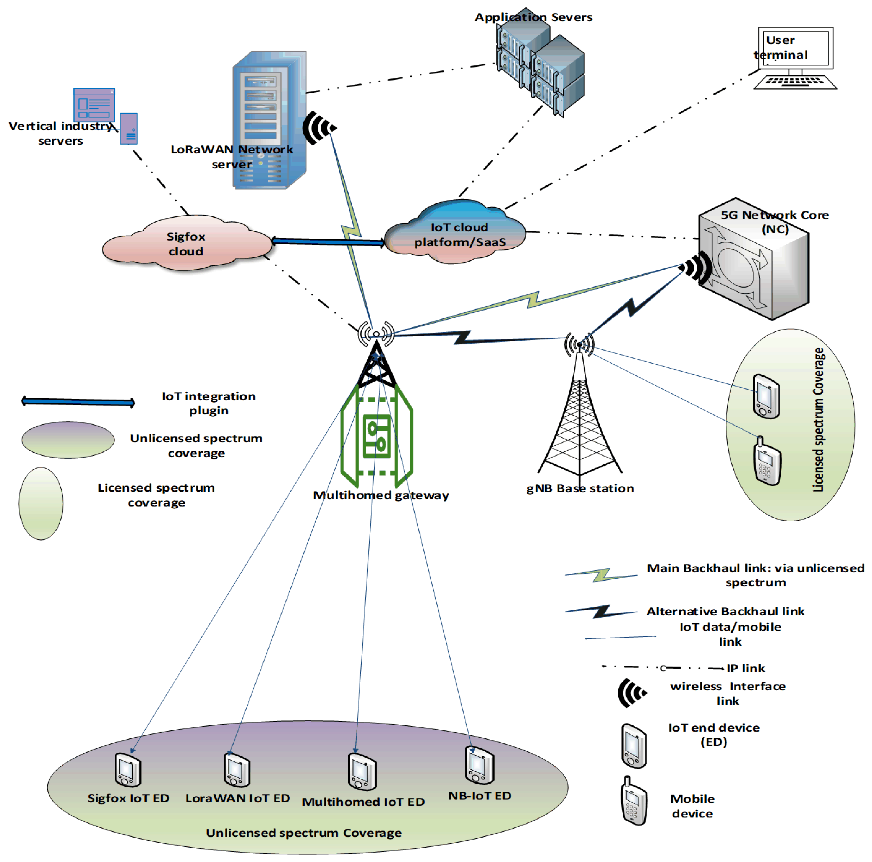
3.1. Lightweight Heterogenous Multihomed Network (LHM-N) Architecture

The LHM-N architecture ensures the connection of sensing end devices (EDs), gateway/radio modules, and end-to-end connectivity to the various servers and entities. This helps the transmission of status, sensed data, and control messages throughout the entire IoT ecosystem. The adopted architecture in LHM-N employs a special mixed topology approach:
(i)
The usual cellular network topology, in which EDs communicate directly with gateway/base station (BS), then from BS to network server/entity, and then to the IoT cloud.
(ii)
The communication of EDs with the gateway, then from the gateway directly to the cloud, and then to the server.
The network employs a 5G private network as the main backhaul over an unlicensed spectrum band. In cases where there is no available 5G private network, a licensed 5G public network is utilized as an alternative backhaul from the commercial cellular network operator. Figure 1 demonstrates the end-to-end connectivity and highlights the network architecture in LHM-N, which comprises the following:
IoT end devices (EDs): This consists of single EDs and multihomed EDs. The single EDs are Sigfox ED, LoRaWAN, and NB2-IoT. The multihomed ED is the LHM-N access ED module, which contains the following interfaces: Sigfox, LoRaWAN, and RedCap interface. The IoT EDs communicate directly with the LHM-N gateway.
Multihomed LHM-N Gateway: This contains multi-radio interfaces that are built on top of a lightweight Raspberry Pi Zero. The multi-radio interfaces include Sigfox, LoRaWAN, RedCap, and NB2-IoT. The block diagram of the multihomed LHM-N gateway is shown in Figure 2. It communicates with EDs through its various interfaces, then transmits collected information via the main backhaul 5G private network over the license-free band to various designated servers. If the 5G private network is not available, the information destined for the 5G core network server is routed via a licensed 5G public network as an alternative backhaul for data delivery.
gNB base station: This is a 5G base station that communicates directly with mobile devices. It also communicates with the LHM-N gateway and serves as an alternative backhaul in transmitting data to the 5G server via the 5G public network.
5G core network: Leverages a service-based architecture comprising many interconnected 5G Network Functions (NFs). The collected information is provisioned in the IoT cloud/software as a service (SaaS). LoRaWAN network server: Processes the data collected from a LHM-N gateway, which is then provisioned to various application servers.
Application servers: These servers house respective processed information collected from the LoRaWAN network server, which can further be provisioned to the IoT cloud/SaaS. Sigfox cloud: This is the cloud hub that directly stores received data from the multihomed gateway via the Sigfox radio interface. The stored data can be integrated into the IoT platform/SaaS via an IoT-integrated plugin from the application backend for better management and usability. The Sigfox data are also accessible by vertical industry IoT solutions. Vertical industry servers: Vertical industry, such as the IoT solutions industry’s servers, collects Sigfox data for monitoring and proper management of EDs, including data visualization and analytics. This will enable efficient data usage.

3.2. Design Methodology of the LHM-N Model

We shall look at the overview of the technologies adopted in this model and the design methodology as follows:

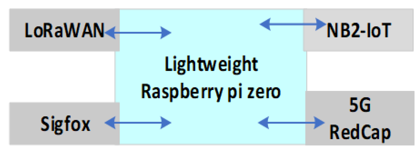
3.2.1. Overview of Technologies Adopted

The technologies employed in this paper range from fundamental to emerging technologies, thus, leading to the novel proposed LHM-N model for IoT applications solution in smart cities scenario. As stated earlier, the model considers a 5G private network over a license-free band. The 5G new radio unlicensed (5G NR U) is part of the aspect that has been finalized in the recent 3GPP release-17 [6]. It will enable industries and private networks to leverage sub-7 GHz as well as the millimeter wave (60 GHz) spectrum band for IoT and broadband solutions. Also, 1.9 GHz is a license-free band in the sub-7 GHz bannd. The 1.9 GHz band has been well advocated for supporting eMTC and industrial IoT (IIoT) technologies’ devices by Multefire Alliance [40,41]. Further, the 5G RedCap IoT device is well suited for medium to high IoT applications, including IIoT [42]. The 5G RedCap IoT device operates on both licensed and unlicensed spectrums. However, the 5G RedCap IoT will need to be well modified to have features nearer to an LPWAN. This modification or optimization may entail the employment of reliable technologies to be implemented at the physical (PHY) layer of the 5G RedCap IoT. The optimization will enable 5G RedCap IoT to support diverse LPWAN-IoT applications in smart city scenarios. One of the reliable technologies that can be implemented on RedCap is the Trellis code modulation (TCM). The TCM is a bandwidth-efficient scheme that is accomplished using convolutional code. It conserves bandwidth by doubling the constellation points of the signal, thus increasing the bit rate, but the symbol rate remains the same [43]. Hence, TCM is bandwidth and energy-efficient error correction coding (ECC) without a complexity cost, unlike the conventional ECC by Shannon’s law, in which there is a trade-off between bandwidth and energy with complexity cost [44].
However, the author of TCM did not take into consideration a Rayleigh fading distribution; rather it was modeled under an additive white gaussian noise (AWGN) channel. For this scheme to work effectively over a Rayleigh fading channel distribution, there is a need to implement it alongside a technology that will produce a satisfactory result. A smart city is a typical terrain that requires Rayleigh fading channel distribution to model communication access technologies and application use cases in a smart city scenario. This is because several buildings in the city cause a non-line of sight (NLOS) and scattering of the wireless signal due to the multipath fading (Rayleigh fading). To overcome this shortfall, this work proposes a receiver diversity-based TCM technique, RX-TCM. Hence, the RX-TCM protocol alongside the LHM-N model is proposed to support medium to high data rate IoT applications. The RX-TCM protocol will be implemented on the LHM-N model for diverse IoT applications as a solution in smart cities scenarios. The LHM-N model consists of a multihomed LHM-N gateway and a multihomed LHM-N end device (ED). Both maintain the same technologies as well as the same radio module interfaces, except that the former has NB2-IoT and higher complexity in addition to supporting numerous LPWAN-IoT devices. Hence, the LHM-N model employs the following technologies.
  • 5G NR U: specifically, the 1.9 GHz band advocated by the Multifire Alliance
  • Private 5G network
  • 5G RedCap IoT
  • RX-TCM
These technologies are implemented specifically on the PHY layer of the RedCap radio module interface. Other radio module interfaces in the multihomed device are meant to offload dense IoT data to their respective use cases depending on the application’s requirements. The RedCap interface is meant to support medium to high data rate IoT applications that cannot be supported by other low-data LPWANs (LoRaWAN, Sigfox, eMTC, and NB2-IoT) in smart city scenarios. This coordinated coexistence of the LPWAN technologies in a multihomed strategy will help to mitigate interference and congestion while improving the QoS of the IoT connectivity in heterogeneous dense smart city environments. The next section demonstrates the design methodology of the LHM-N model.

3.2.2. Design Methodology
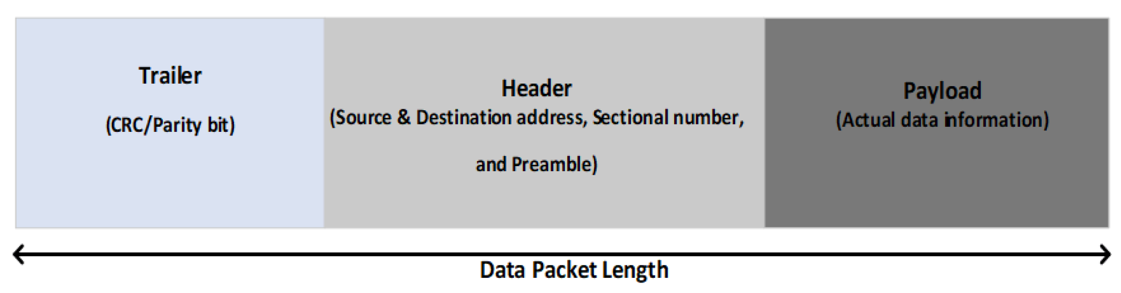
There are two phases in the design methodology. The packet size forwarding engine and the model.
Phase 1: Packet-Size Forwarding Engine Algorithm: The function of the packet-size forwarding engine (PSFE) algorithm is to forward packets from the multihomed input interface to the appropriate output chipset interfaces. This will enable each chipset interface to transfer the packet to its final destination. The PSFE algorithm will forward data packets to appropriate interfaces based on their respective payload size threshold. Specifically, data packets forwarded or destined to the 5G RedCap IoT device interface will work according to the optimized model transmission mechanism. However, data packets forwarded to other interfaces will be transmitted normally. The data packet format has three major field parameters, which are represented as header, trailer, and payload. The header contains source and destination information, including fragments and the current sectional numbers. The trailer field includes a frame checksum sequence for error control with cyclic redundancy check (CRC) or parity bits. The payload is the actual data information being transmitted. Each field holds a size or length of data bits; the header and trailer have a smaller length, while the payload has a longer length containing the actual data bits information. Figure 3 shows the packet length information. Actually, packet forwarding uses information in the header field to forward the payload data to the appropriate chipset interfaces.
Formulation of Optimization Problem for the PSFE: The forwarding of packets is carried in the forwarding plane of the multihomed gateway/ED. The length of a packet is denoted as L and a chunk or block of packets is denoted as B. A block of packet length is represented as B L . A block of originating packet length from the input of the gateway to be forwarded to the output chipset interface is denoted by B L O . This packet length is based on the payload size. For a packet to be forwarded, a number of optimization problem conditions must be met:
(i)
The payload must attain a general minimum threshold size denoted as B L G M i n or a block of general minimum threshold packet length.
(ii)
The specific port address must be known, which is denoted as P o r t A d d r .
(iii)
The block of the originating packet length B L O must move to the block of the packet forwarding state, denoted as B L F .
Hence, the probability of packet forwarding P r P F is the probability of B L G M i n or B L F and P o r t A d d r , which is expressed as P r P F .
P r P F = P r [ ( ( B L G M i n ) + ( B L F ) ) ( P o r t A d d r ) ]
Then, the probability of no packet forwarding is
P r N P F = 1 P r P F
Algorithm 1 illustrates the PSFE for forwarding a block of data packets to the respective chipset interfaces.
Algorithm 1: Packet-size forwarding engine (PSFE) algorithm.
1. Initializes→ B L O ; B L G M i n B L F ; % Block of originating, general minimum threshold, and
forwarding packet length, respectively;
2. For B L G M i n <= B L F ;
3.        Move packet block to forwarding state;
4. if B L O >= B L G M i n ;
5.       Determine interface port address;
6. if B L O < B L ( m i n R C ) ;
7.         re-route or find appropriate interface;
8. else if P o r t A d d r = P o r t R C && B L O >= B L ( m i n R C ) && B L O <= B L ( m a x R C ) ;
9.        Forward B L O to RedCap;
10. else if P o r t A d d r = P o r t N B && B L O >= B L ( m i n N B ) && B L O <= B L ( m a x N B ) ;
11.        Forward B L O to NB2-IoT;
12. else if P o r t A d d r = P o r t L R && B L O >= B L ( m i n L R ) && B L O <= B L ( m a x L R )
13.          Forward B L O to LoRaWAN;
14. else if P o r t A d d r = P o r t S F && B L O >= B L ( m i n S F ) && B L O <= B L ( m a x S F )
15.        Forward B L O to Sigfox;
16. While B L O < B L ( m i n S F ) ;
17.        No packet forwarding;
18. If B L O + 1 ; %increment by 1 by additional packet length.
19.        Move to appropriate interface packet threshold.
20. else;
21.        Wait for attainment to any interface packet threshold before forwarding;
22. While B L O + 1 >= B L F ;
23.Forward incremented B L O to appropriate interface;
24. else;
25.        Move to initialize B L G M i n then to B L F state
26. end if;
27.end; end; end; end; end;
Algorithm 1 symbols
  • B L O : Block of originating packet length
  • B L G M i n : Block of general minimum packet threshold
  • B L F : Block of packet forwarding state
  • B L ( m i n R C ) : Block of minimum packet threshold for RedCap interface
  • P o r t A d d r : Port address
  • P o r t R C : RedCap port address
  • B L ( m i n S F ) : Block of minimum packet threshold for Sigfox interface
Algorithm 1 Explanation: The block of originating packet length, B L O , initializes the attaining of the general minimum packet threshold, B L G M i n , as well as the block of packet forwarding state, B L F . Data packets should move to the packet forwarding state so long as the B L G M i n is less than or equal to B L F . PSFE should identify the specific interface port address if B L O is greater than or equal to B L G M i n , and if B L O is less than the block of minimum packet threshold for the RedCap interface B L m i n R C . Otherwise, if the identified port address, P o r t A d d r is the RedCap port address, P o r t R C , and the B L O is less than or equal to B L m i n R C , and the B L O is also less than or equal to the maximum packet threshold for the RedCap interface, B L m a x R C , then B L O should be forwarded to the RedCap interface. The same conditions also hold for NB2-IoT, LoRaWAN, and Sigfox. Therefore, as long as B L O is less than the minimum packet threshold for the Sigfox interface, B L m i n S F , no packet should be forwarded. If B L O is incremented by 1 when there is an additional packet length, the B L O should move to the appropriate interface packet threshold. Otherwise, it should wait for attainment to any interface packet threshold before forwarding. While the incremented B L O is greater than or less than B L F , it should be forwarded to the appropriate interface. Else it should move to initialize B L G M i n , then to B L F state. End if conditions are met, otherwise the process begins again, then ends.
Benefits of the PSFE Algorithm: PSFE uses a strategy that allows data packets to fulfill certain conditions before forwarding. Instead of forwarding packets arbitrary and too frequently, packets are accumulated to a substantial level before forwarding to their respective interfaces. This is because frequent packet forwarding causes excessive overheads to the packet header and trailer, thereby leading to errors, a sluggish network, and high energy.
P O = T o t a l   p a c k e t l e n g t h p a y l o a d T o t a l   p a c k e t l e n g t h
The total packet length comprises the header length, trailer length, and payload size. The smaller the value of the protocol overhead, the better the efficiency of the device protocol. Further, because the PSFE does not follow conventional packet forwarding, session hijacking and injection attacks that use conventional brute force attack methods are overwhelmed and circumvented. Hence the benefits of PSFE includes:
  • Minimized packet-error forwarding
  • Energy-efficient packet forwarding
  • Lightweight and less overhead packet forwarding
  • Reliable network packet forwarding
  • Mitigation of session hijacking and injection attacks
Phase 2: The Model: The design of the LHM-N model considers a system model comprising a transmitter (Tx) and a receiver diversity with two receiver (Rx1 and Rx2) systems; that is, a single-input multiple-output (SIMO) system. Figure 4 illustrates the receiver diversity (RX)-TCM system model. The transmitter is responsible for sending a bit stream (message signal), which has been encoded by the TCM encoder and modulated by a 16-QAM (quadrature amplitude modulation) modulator before transmitting. A Rayleigh fading channel is considered during this transmission. The signals received by the two receiving antennas are combined by the maximum ratio combiner (MRC) technique. The corresponding output is then demodulated and decoded by the TCM decoder; the result is then checkmated with the initial bits stream by the bit error rate (BER) estimator for error performance computation.
Assuming the channel state information (CSI) is known at the receivers’ side, the received signal y is represented as
y 1 = h 1 x + n 1
y 2 = h 2 x + n 2
where y 1 is the signal received by antenna 1, h 1 is the fading channel at antenna 1, x is the transmitted coded signal, and n 1 is the Gaussian noise coefficient at antenna 1. Similarly, y 2 is the signal received by antenna 2, h 2 is the fading channel at antenna 2, and n 2 is the Gaussian noise coefficient at antenna 2. Since the fading channel h is a complex coefficient with real and imaginary parts, the conjugate of h, that is h * together with a square of h modulus, | h | 2 , is applied to obtain the signal equalization z, given as:
z 1 = h 1 * y 1 = | h 1 | 2 x + h 1 * n 1
z 2 = h 2 * y 2 = | h 2 | 2 x + h 2 * n 2
Finally, the combined received signal y c is given by:
y c = z 1 + z 2 / | h 1 | 2 + | h 2 | 2
Then the transmitted coded symbol is estimated from the combined received signal using the Viterbi decoding algorithm together with a soft detection metric, such as the maximum likelihood detector (MLD). The MLD is computed based on the squared free distance ( d f r e e 2 ) , which is the smallest Euclidian distance of the coded symbol sequence to the all-zero symbol sequence bits [45]. This process of estimation with detection will account for the sent TCM convolutional coded bits and constellation mapping of the 16-QAM. Since the transmitted coded signal is over a Rayleigh fading channel distribution, the error performance of the 16-QAM signal, that is, the symbol error rate of the QAM signal ( S E R ( Q A M ) ) in the Rayleigh fading channel, is given by:
S E R Q A M = 0 P S E R Q A M ( ( γ ¯ | γ ) ) f γ ( γ ) d γ
where ( γ ) is the signal-to-noise ratio (SNR), γ ¯ is the average SNR, P S E R Q A M is the symbol error probability of the QAM signal, and f γ ( γ ) is the probability density function (PDF) of ( γ ) . Hence, the SNR, ( γ ) is given as
γ = E s / N 0
f γ ( γ ) = 1 γ ¯ e x p ( γ ) γ ¯
where E S is the symbol energy per bit, and N 0 is the Gaussian noise coefficient. Then, considering the SNR combined signal γ c , the PDF of γ c is given by
f γ c s ( γ c s ) = γ c s N r a 1 γ ¯ N r a N r a 1 ! e x p γ c s γ ¯
where N r a is the number of receiving antennas. Hence, the P S E R Q A M for the combined signal in a Rayleigh fading channel is given by
P S E R Q A M = 0 a n exp b γ c s 2 2 a exp b γ c s 2 + ( 1 a ) i = 1 n 1 exp b γ c s s i + i = n 2 n 1 exp b γ c s s i                                                           × γ c s N r a 1 γ ¯ N r a N r a 1 ! e x p γ c s γ ¯ d γ c s
Applying trapezoidal simplification gives
P S E R Q A M = a n 1 b γ ¯ + 2 N r a a 2 1 γ ¯ + 1 N r a + ( 1 a ) i = 1 n 1 s i b γ ¯ + s i N r a + i = n 2 n 1 s i b γ ¯ + s i N r a
where
a = 1 1 M , b = 3 M 1 , s i = 2 sin i π 4 n ,
The next section provides the implementation in MATLAB.

4. Implementation of the LHM-N Model

4.1. Implementation Overview

The implementation is conducted in MATLAB. Reliable results are achieved in modeling and simulations that are based on discrete events simulations (DES). For instance, an autoregressive integrated moving average (ARIMA) based on the DES method was used to generate a reliable result with minimal error in smart framing [46]. Further, soft computing optimization based on the DES approach was used for the modeling and simulation analysis for a reliable mechanized operation solution [47]. Hence, the LHM-N model is based on DES. The illustrative phase of the LHM-N model implementation is shown in Figure 4. In the simulation, a random binary bit stream was created. The bit stream is then encoded into a convolutional code by the TCM encoder. The coded bit is then mapped to a 16-QAM modulator, which modulates the coded bit streams. A Rayleigh fading channel is then added to the modulated data in order to simulate a multipath fading channel. Then, the MRC combines the data received by the two receivers, which the simulation prepares for demodulation and decoding by the Viterbi decoder. Finally, the simulation compares the decoded information with the original bits streams in order to compute the bit error rate (BER).

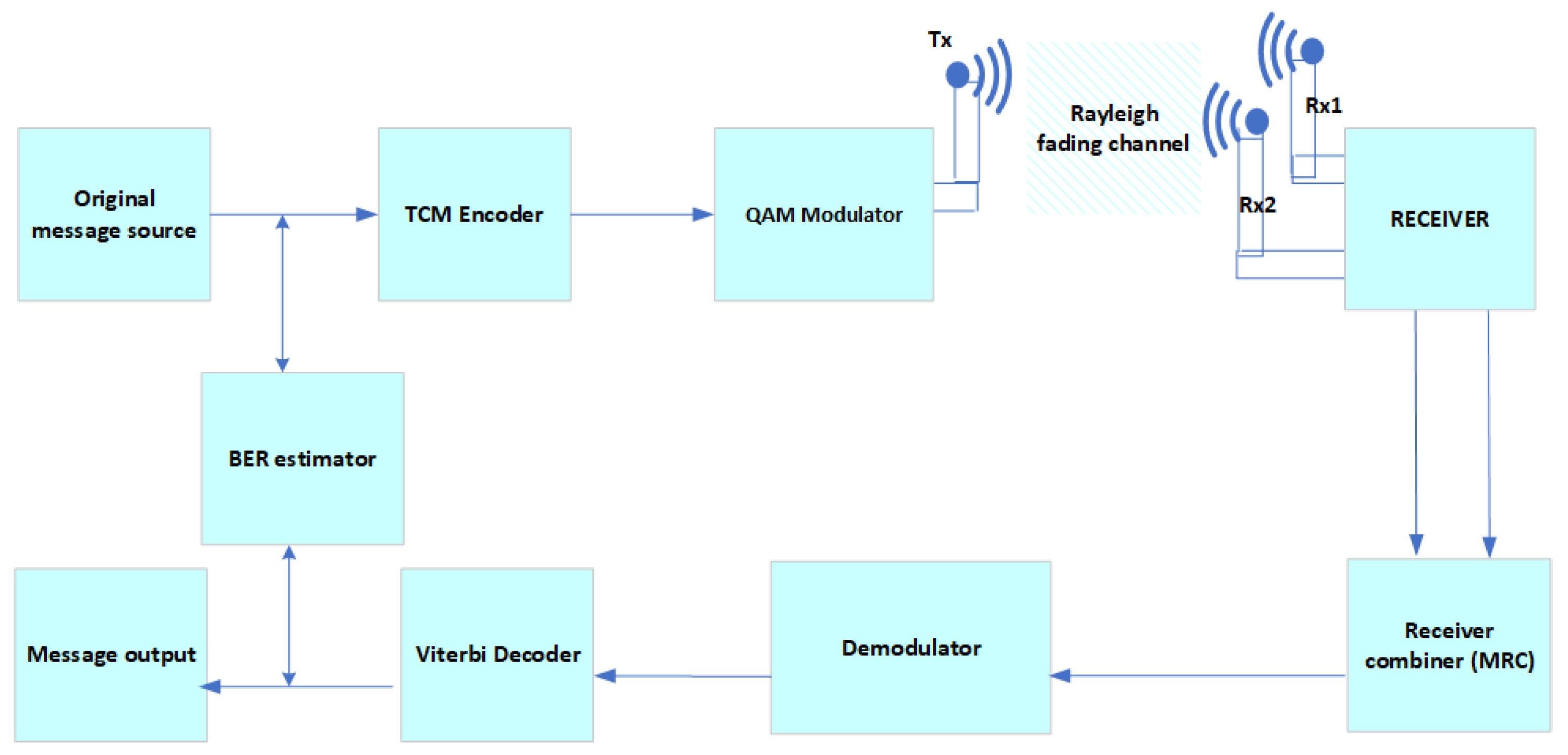
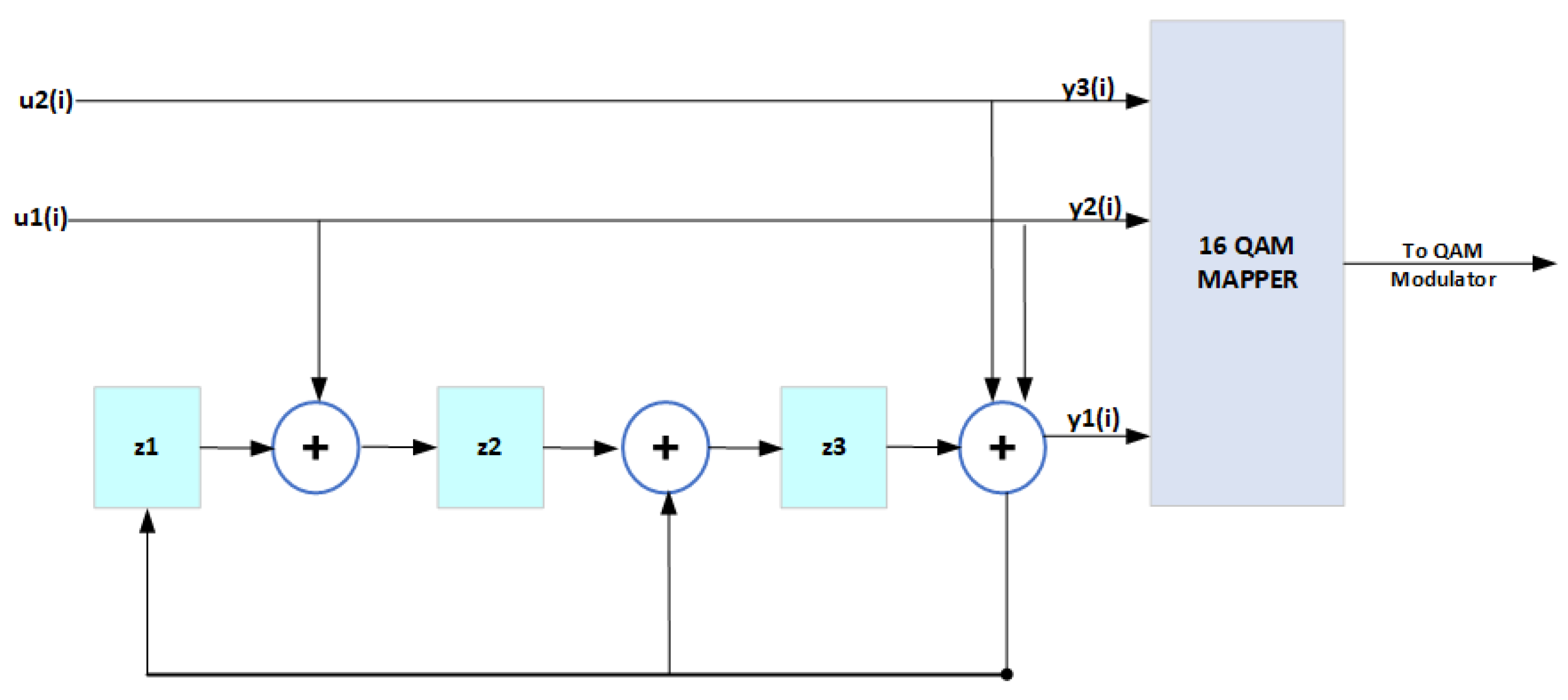
4.2. The TCM Encoder Implementation
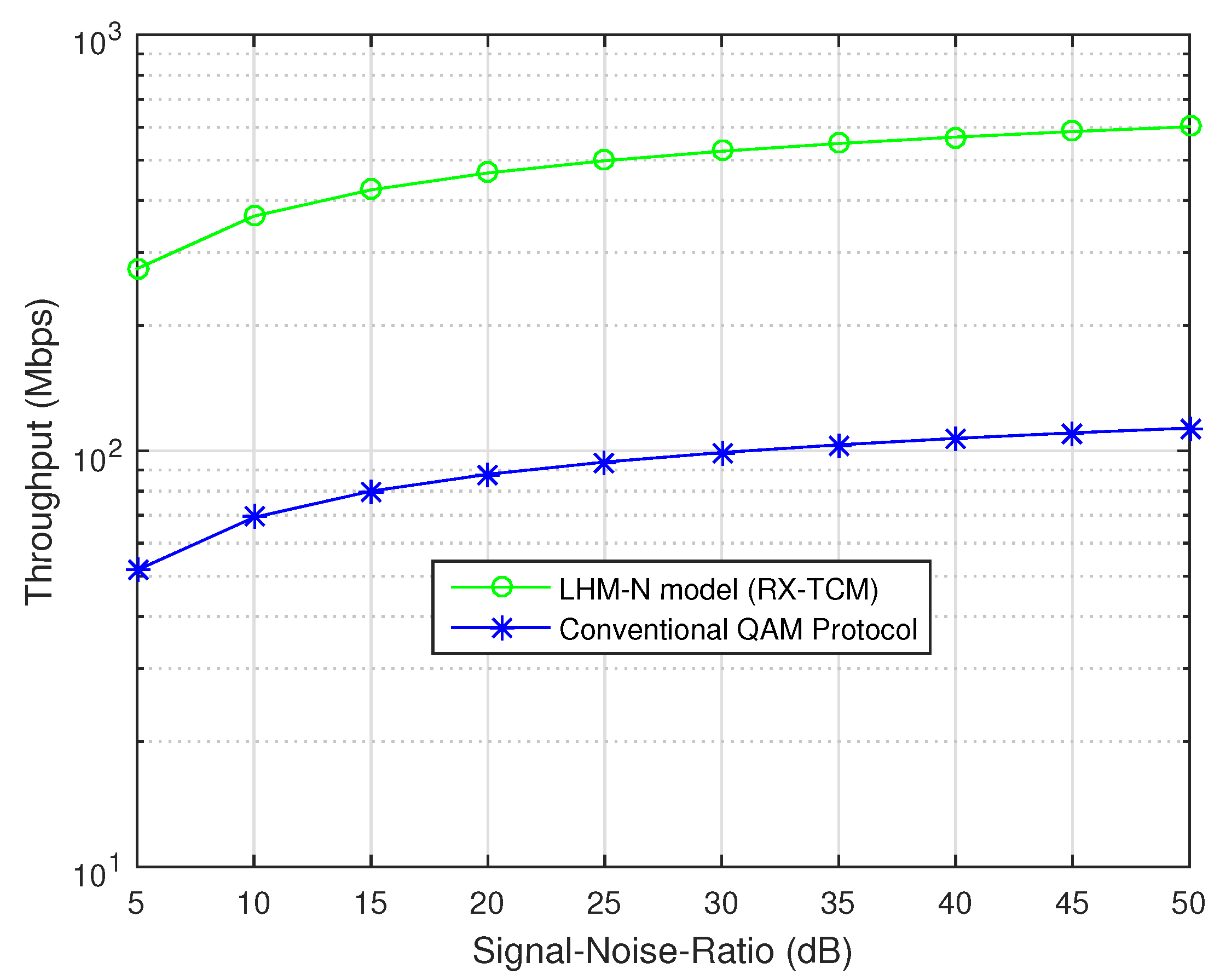
The TCM encoder is represented by ( n , k , m ) convolutional code parameters; where n is the output, k is the input, and m is the memory register. The coding rate R is configured as k / n . For example, R = 2 / 3 means 2 input message streams and 3 coded output bit streams. This model considers (3,2,3) convolutional code, wherein z1, z2, and z3 represent the three memory registers, and R = 2 / 3 . The constraint length L is determined by m + k . Figure 5 depicts a coding rate of a 2 / 3 TCM encoder, in which the coded bit stream is mapped by the QAM mapper to the QAM modulator. Hence, the convolutional code equation is given by,
y ( i ) = u ( i ) G
The output y ( i ) is dependent on the input u ( i ) and on the previous input u ( i 1 ) , u ( i 2 ) , u ( i 3 ) , , where i denotes the passing time, and G is the generator matrix. Now, considering k = 2 , n = 3 , and m = 3 as in our case of R = 2 / 3 for the 16 QAM signal, here, the input bits u(i) are transformed into the output vectors y ( i ) = ( y 1 ( i ) , y 2 ( i ) , y 3 ( i ) ) by the following encoding equation:
y ( i ) = ( y 1 ( i ) = u ( i ) + u ( i 3 ) , y 2 ( i ) = u ( i ) + u ( i 1 ) + u ( i 2 ) , y 3 ( i ) = u ( i ) + u ( i 1 ) + u ( i 2 ) + u ( i 3 ) )
From the above encoder, it can be seen that i needs to remember the three previous input bits u ( i 1 ) , u ( i 2 ) and u ( i 3 ) . The contents of the three memory bits juxtapose the encoding function. Thus, at any time i, the encoder is in a previous state or new state designated by the state vector s ( i ) .
s ( i ) = ( s 1 ( i ) , s 2 ( i ) , s 3 ( i ) = u ( i 1 ) , u ( i 2 ) , u ( i 3 ) )
The convolution code can be encoded with a polynomial generator G. The matrix representation of a polynomial generator G is given by
G = g 0 ( 1 ) g 0 ( 2 ) g 0 ( n ) g 1 ( 1 ) g 1 ( 2 ) g 1 ( n ) g 2 ( 1 ) g 2 ( 2 ) g 2 ( n ) g m ( 1 ) g m ( 2 ) g m ( n )
where g i = ( g 0 ( 1 ) g 0 ( 2 ) g 0 ( n ) ) , 0 i m . The generator g ( i ) is the polynomial connection and can be represented in binary or octal format. It can also be represented in the transform domain, D (delay operator) form, which is given by the following convolutional code equation as
y ( D ) = u ( D ) G ( D )
thus, the polynomial generator matrix in a D-transform domain is given as,
G ( D ) = g 0 ( 1 ) ( D ) g 0 ( 2 ) ( D ) g 0 ( n ) ( D ) g 1 ( 1 ) ( D ) g 1 ( 2 ) ( D ) g 1 ( n ) ( D ) g 2 ( 1 ) ( D ) g 2 ( 2 ) ( D ) g 2 ( n ) ( D ) g m ( 1 ) ( D ) g m ( 2 ) ( D ) g m ( n ) ( D )
A particular TCM code (n, k, m) parameter can be encoded by many polynomial generators g i . Not all polynomial generators are good. Hence, g ( i ) depends on the number of trellis states and d f r e e 2 to give a good asymptotic coding gain for GT. The number of trellis states is depicted by 2 m . For example, in our case of the 16 Q A M (3,2,3) TCM encoder parameters, the trellis state is 8. The d f r e e 2 is estimated by the smallest Euclidian distance of a coded symbol sequence to the all-zero symbol sequence. The TCM asymptotic coding gain of GT is given by
G T = 10 l o g [ ( ( d f r e e 2 ) / ( d ( m i n u ) 2 ) ) ( E ( s u ) / E s ) ]
where d f r e e 2 is the squared free distance of the TCM encoder and d ( m i n u ) 2 is the squared minimum Euclidian distance of the uncoded scheme; E ( s u ) and E s are the symbol energy of the uncoded scheme and TCM encoder, respectively. Table 1 illustrates optimal polynomials generators/connections g ( i ) in octal (base 8) format with the associated parameters for a good TCM encoder.

4.3. Throughput

Adequate asymptotic Gain G T will improve the data rate throughput ( T d r ) of a communication signal. From Shannon’s law, the throughput of an uncoded scheme is given by
T ( d r u ) = C B ( l o g 2 ) ( 1 + S N R )
Hence, the throughput for coded scheme T ( d r G T ) gives
T ( d r G T ) = C B ( G T ) ( l o g 2 ) ( 1 + S N R )
where CB is the channel bandwidth of the carrier signal. The next section presents the simulation setup for the model implementation.

4.4. Simulation Experimental Setup

Table 2 presents the parameters for the simulation of the LHM-N model implementation and PSFE algorithm. The model is experimented with and compared with the conventional QAM protocol. The performance efficiency of the implemented model is evaluated based on the following instances:
(1)
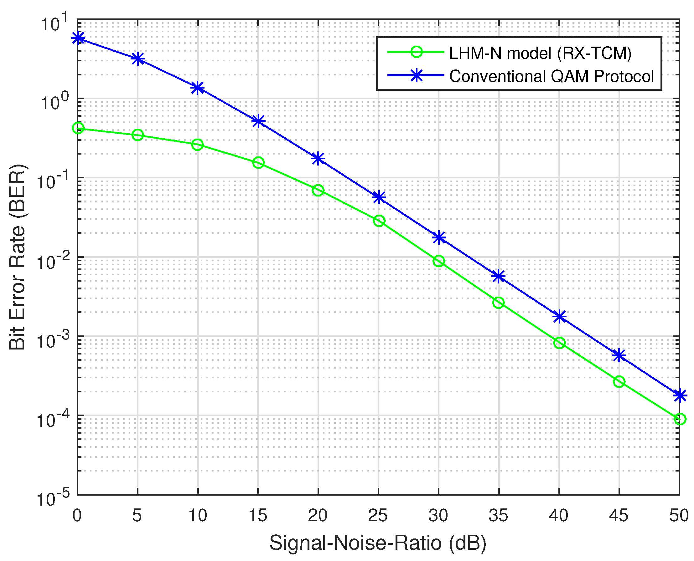
Evaluation with respect to BER and SNR over a Rayleigh fading channel.
(2)
Evaluation with respect to throughput and SNR over a Rayleigh fading channel.
(3)
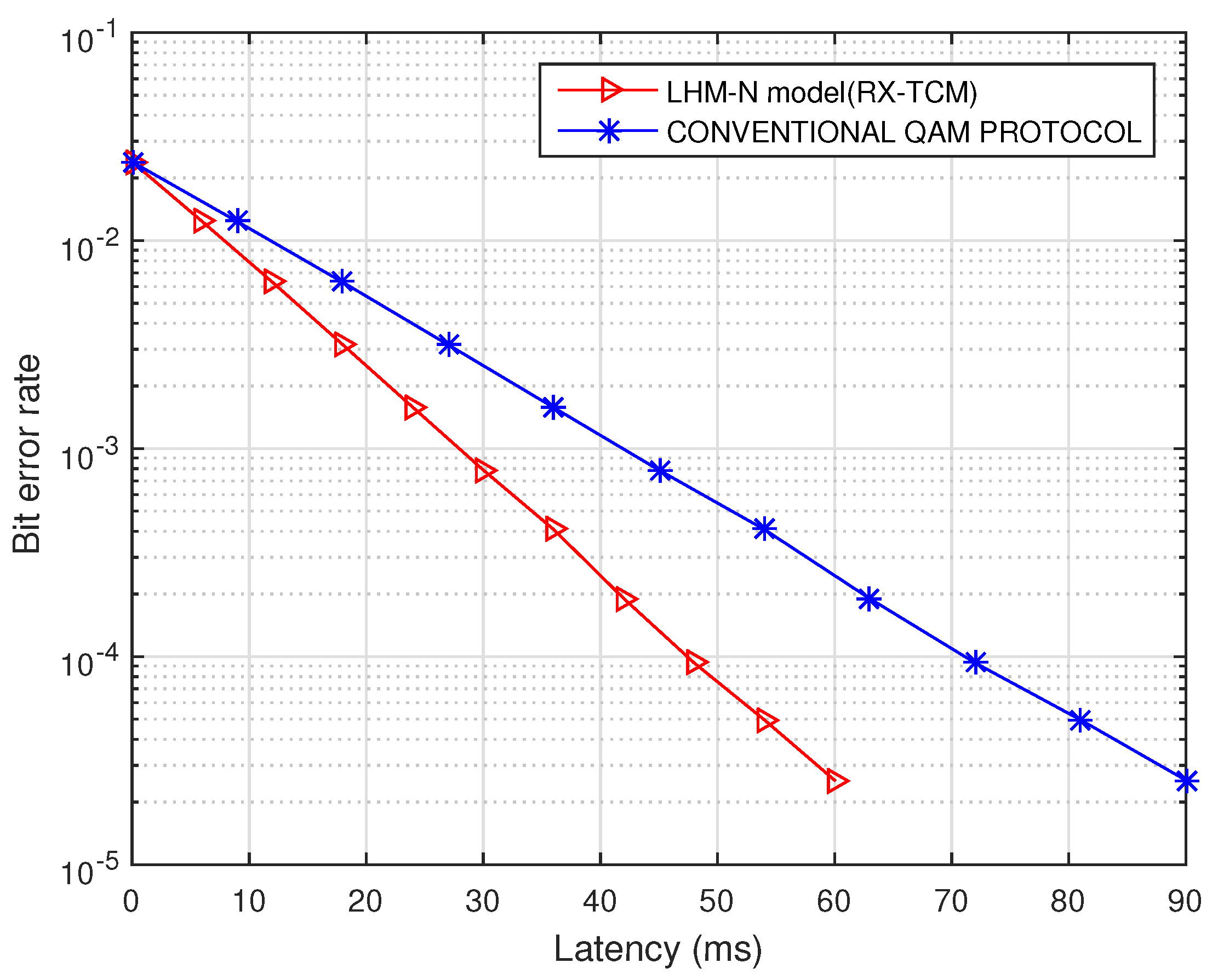
Evaluation with respect to bit error rate (BER) and latency over a Rayleigh fading channel.
Further, the PSFE algorithm is experimented with and compared with TCP Reno and TCP Cubic algorithms for packet forwarding. TCP Reno uses slow start and fast retransmit, including packet loss, as criteria to detect network congestion during packet transmission. TCP Cubic uses a cubic function of time from the inception of the last packet loss with the inflection point set to the window prior to the congestion occurrence during packet transmission. These algorithms are compared with the PSFE algorithm in terms of packet forwarding to the device interface.

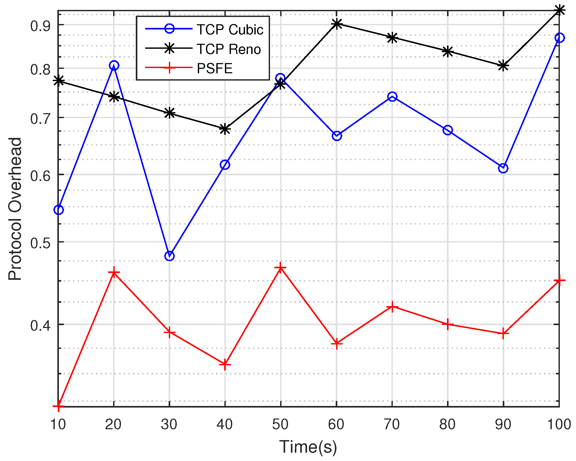
5. Result and Analysis

Figure 6 shows the performance of communication signal transmission with respect to BER and SNR over the Rayleigh fading channel of the LHM-N model compared with the conventional QAM protocol (uncoded scheme). From Figure 6, it can be deduced that the bit error rate (BER) at a given SNR in the LHM-N model is lower than the bit error rate in the conventional QAM protocol. For example, the LHM-N model exhibits a lower BER below 1, approximately 0.5 at an SNR of 5 dB, whereas the conventional QAM protocol exhibits a higher BER above 1, approximately 6 at the same SNR of 5 dB. Further, at an SNR of 50 dB, the BER in the LHM-N model is 10 4 , whereas the BER in the conventional QAM protocol is above 10 4 . Therefore, it is apparent that it will take lower errors for communication signal transmission in the LHM-N model than in the conventional QAM protocol, which has more errors in transmission, as depicted in Figure 6. Hence, the LHM-N model coding gain GT of 5.3 dB validates the performance improvement without the expense of bandwidth energy. For example, at a given SNR (a function of symbol energy per bit), the communication signal improves with less error compared to the conventional QAM protocol at the same symbol energy per bit.
Figure 7 shows the performance of the communication signal transmission with respect to throughput and SNR over the Rayleigh fading channel of the LHM-N model compared with the conventional QAM protocol. From the result, it confirms that the LHM-N model can effectively maintain a higher throughput or data rate in communication signal transmission. This is depicted in Figure 7, which shows a higher throughput than the existing or conventional QAM protocols (uncoded signal). For instance, for the LHM-N model, at an SNR of 25 dB, a throughput of approximately 800 Mbps is obtained whereas for the existing QAM protocol, approximately 100 Mbps throughput is obtained at the same 25 dB. Similarly, at an SNR of 50 dB, throughputs of approximately 850 and 150 Mbps are obtained for the LHM-N model and existing QAM protocol, respectively. Hence, it is evident that the throughput of the LHM-N model is five times the throughput of the existing QAM protocol. This validates an appreciable and improved throughput in the LHM-N model than in the existing QAM protocol. This throughput improvement makes this model (an optimization of a 5G RedCap IoT device) suitable for medium to high data rate IoT applications without the expense of energy increase (low power). Thus, this model has a comparable LPWAN potential capability. The 5G RedCap IoT device with the existing protocol cannot attain appreciable throughput without the expense of energy increase (high power consumption), which makes it unsuitable for LPWAN-IoT potential capability. Hence, the existing RedCap does not support low power capability comparable with the LPWAN.
Figure 8 shows the performance of the communication signal transmission with respect to BER and latency over the Rayleigh fading channel of the LHM-N model compared with the conventional QAM protocol. From the result, it can be seen that at any instance of the transmission, the LHM-N model exhibits low BER as well as a lower latency compared to the conventional QAM protocol For example, the transmission latency is 30 ms with a BER slightly below 10 3 in the LHM-N model. Whereas at the same BER of 10 3 , the transmission latency or delay was 45 ms in the conventional QAM protocol. This validates the lower latency or delay in the LHM-N transmission than in the conventional QAM protocol.
Figure 9 shows comparisons of the protocol overhead for packet forwarding transmission. From the three evaluated algorithms, the PSFE algorithm outperforms TCP Reno and TCP Cubic algorithms with very low protocol overhead throughout the simulation runtime during the packet-forwarding transmission. The PSFE has a maximum attainment of 0.5 protocol overhead. This is the least attainment of protocol overhead compared with TCP Reno and TCP Cubic, whose maximum protocol overheads are 0.9 and 0.8, respectively. Hence, the TCP Reno and TCP Cubic encountered higher protocol overhead due to the frequent packet forwarding in their algorithm’s criteria. This causes excessive overhead for the packet header and trailer, which can lead to packet loss errors, sluggish network, congestion, and high energy consumption on the device. However, the PSFE maintains conditional properties based on a given threshold for packet forwarding. This allows only accumulated packets to be forwarded based on the conditional criteria leading to minimal protocol overhead. The minimal protocol overhead can be attributed to enabling congestion avoidance in packet-forwarding transmission.

6. Conclusions and Future Work

In this paper, the design and implementation of a lightweight heterogenous multihomed network (LHM-N) model for diverse smart city applications is carried out. The LHM-N model addresses dense heterogeneity network challenges, such as the difficulties in the management of LPWANs coexistence, interference, spectrum insufficiency, QoS, and scalability issues, in a smart cities’ scenario. The solution model advocates the enabling of smartness in the diverse IoT application domains, such as transport and mobility, health care, natural resources, electricity and energy, homes and buildings, commerce and retail, society and workplace, industry, agriculture, and the environment. A receiver diversity-based TCM technique, RX-TCM, is implemented on the LHM-N model for the IoT application solution suitable for a smart city ecosystem. In addition, the paper integrates a manageable license-free LPWAN coexistence with 5G private and public cellular networks in the LHM-N model. This provides a very cost-effective solution model in a heterogeneous dense smart city environment. Further, a 5G reduced capability (RedCap) IoT device is integrated into the (LHM-N) model for supporting high-bandwidth smart city application solutions. Furthermore, the optimization of the PHY layer protocol of the 5G reduced capability (RedCap) IoT device to operate comparatively with LPWAN in terms of signal-to-noise ratio (SNR) symbol energy is carried out. The 5G RedCap performs optimally at medium to high data throughput with low latency in the LHM-N model.
Furthermore, the MATLAB simulation results validate the performance of the LHM-N model with a lower error rate and lower transmission delay compared to the conventional QAM protocol. The 5G RedCap protocol optimization performs five times better than the conventional QAM protocol in terms of data throughput without an energy cost expense for medium- to high-bandwidth industrial IoT (IIoT) applications. In addition, the proposed packet-size forwarding engine (PSFE) algorithm outperforms TCP Reno and TCP Cubic algorithms with very low protocol overhead. Finally, the minimal protocol overhead in the PSFE algorithm can be attributed to enabling congestion avoidance in packet-forwarding transmission.
Regarding future work, the authors aim to carry out coverage and energy/complexity evaluations of the developed LHM-N model compared with conventional LPWANs, such as LTE-M (eMTC), in a smart city scenario. This is to establish the nearness of the LHM-N model features to features of the LPWAN in a smart city scenario.

Author Contributions

Author Contributions: Conceptualization, E.U.O.; methodology, E.U.O.; software, E.U.O. and A.M.K.; validation, E.U.O., A.M.A.-M. and A.M.K.; formal analysis, E.U.O., A.M.A.-M. and A.M.K.; investigation, E.U.O.; resources, A.M.A.-M. and A.M.K.; data curation, E.U.O.; writing—original draft preparation, E.U.O.; writing—review and editing, A.M.A.-M. and A.M.K.; visualization, E.U.O.; supervision, A.M.A.-M. and A.M.K.; project administration, E.U.O., A.M.A.-M. and A.M.K.; funding acquisition, A.M.A.-M. and A.M.K. All authors have read and agreed to the published version of the manuscript.

Funding

This research received no external funding.

Institutional Review Board Statement

Not applicable.

Informed Consent Statement

Not applicable.

Data Availability Statement

Not applicable.

Acknowledgments

The authors acknowledge the resources provided by CSIR, Pretoria, and F’SATI at Tshwane University of Technology, Pretoria, in support of this research.

Conflicts of Interest

The authors declare no conflict of interest.

References

  1. Qadir, Q.M.; Rashid, T.A.; Al-Salihi, N.K.; Ismael, B.; Kist, A.A.; Zhang, Z. Low power wide area networks: A survey of enabling technologies, applications and interoperability needs. IEEE Access 2018, 28, 77454–77473. [Google Scholar] [CrossRef]
  2. Ismail, N.L.; Kassim, M.; Ismail, M.; Mohamad, R. A review of low power wide area technology in the licensed and unlicensed spectrum for IoT use cases. Bull. Electr. Eng. Inform. 2018, 7, 183–190. [Google Scholar] [CrossRef] [Green Version]
  3. Boulogeorgos, A.A.A.; Diamantoulakis, P.D.; Karagiannidis, G.K. Low Power Wide Area Networks (LPWANs) for Internet of Things (IoT) Applications: Research Challenges and Future Trends. arXiv 2016, arXiv:1611.07449. [Google Scholar]
  4. Smail, B.; Sanchez, D.T.; Peconcillo, L.B., Jr.; De Vera, J.V.; Horteza, A.D.; Jawarneh, M. Investigating different applications of Internet of Things towards identification of vulnerabilities, attacks and threats. Int. J. Next-Gener. Comput. 2022, 13. [Google Scholar] [CrossRef]
  5. Raza, U.; Kulkarni, P.; Sooriyabandara, M. Low Power Wide Area Networks: An Overview. IEEE Commun. Surv. Tutor. 2017, 19, 855–873. [Google Scholar] [CrossRef] [Green Version]
  6. Available online: https://www.qualcomm.com/news/onq/2022/03/just-3gpp-completes-5g-nr-release-17 (accessed on 25 May 2022).
  7. Moloudi, S.; Mozaffari, M.; Veedu, S.N.; Kittichokechai, K.; Wang, Y.P.; Bergman, J.; Höglund, A. Coverage evaluation for 5G reduced capability new radio (NR-RedCap). IEEE Access 2021, 9, 45055–45067. [Google Scholar] [CrossRef]
  8. De Poorter, E.; Hoebeke, J.; Strobbe, M.; Moerman, I.; Latré, S.; Weyn, M.; Lannoo, B.; Famaey, J. Sub-GHz LPWAN network coexistence, management, and virtualization: An overview and open research challenges. Wirel. Pers. Commun. 2017, 95, 187–213. [Google Scholar] [CrossRef] [Green Version]
  9. Silva, F.S.; Neto, E.P.; Oliveira, H.; Rosário, D.; Cerqueira, E.; Both, C.; Zeadally, S.; Neto, A.V. A survey on long-range wide-area network technology optimizations. IEEE Access 2021, 9, 106079–106106. [Google Scholar] [CrossRef]
  10. Fadeyi, J.; Markus, E.D.; Abu-Mahfouz, A.M. Technology coexistence in LPWANs-A comparative analysis for spectrum optimization. In Proceedings of the 2019 IEEE 28th International Symposium on Industrial Electronics (ISIE), Vancouver, BC, Canada, 12–14 June 2019; pp. 2244–2249. [Google Scholar]
  11. Hattab, G.; Visotsky, E.; Cudak, M.; Ghosh, A. Uplink Interference Mitigation Techniques for Coexistence of 5G mmWave Users with Incumbents at 70 and 80 GHz. In Proceedings of the IEEE Global Communication Conference, Singapore, 1–2 November 2017. [Google Scholar]
  12. Sandeep, P.A. Comparative Analysis of Optimization Techniques in Cognitive Radio (QoS). Int. J. Eng. Adv. Technol. (IJEAT) 2017, 6, 2249–8958. [Google Scholar]
  13. Onumanyi, A.J.; Abu-Mahfouz, A.M.; Hancke, G.P. Low power wide area network, cognitive radio and the Internet of Things: Potentials for integration. Sensors 2020, 20, 6837. [Google Scholar] [CrossRef]
  14. Ogbodo, E.U.; Dorrell, D.G.; Abu-Mahfouz, A.M. Improved resource allocation and network connectivity in CRSN-based smart grid for efficient grid automation. In Proceedings of the 2019 Conference on Information Communications Technology and Society (ICTAS), Durban, South Africa, 6 March 2019; pp. 1–6. [Google Scholar]
  15. Nurelmadina, N.; Hasan, M.K.; Memon, I.; Saeed, R.A.; Zainol Ariffin, K.A.; Ali, E.S.; Mokhtar, R.A.; Islam, S.; Hossain, E.; Hassan, M.A. A systematic review on cognitive radio in low power wide area network for industrial IoT applications. Sustainability 2021, 13, 338. [Google Scholar] [CrossRef]
  16. Ogbodo, E.U.; Dorrell, D.G.; Abu-Mahfouz, A.M. Radio resource allocation improvements in a cognitive radio sensor network for smart grid: Investigative study and solutions. Int. J. Sens. Wirel. Commun. Control 2021, 11, 666–688. [Google Scholar] [CrossRef]
  17. Hayashi, H.; Ueda, T. Standardization of Wireless Coexistence in Industrial Automation: Application for Hydrogen Station. SICE J. Control. Meas. Syst. Integr. 2016, 9, 44–49. [Google Scholar] [CrossRef]
  18. Chiwewe, T.M.; Mbuya, C.F.; Hancke, G.P. Using cognitive radio for interference-resistant industrial wireless sensor networks: An overview. IEEE Trans. Ind. Inform. 2015, 11, 1466–1481. [Google Scholar] [CrossRef] [Green Version]
  19. Javed, Q.; Prakash, R. Chameleon: A framework for coexistence of wireless technologies in an unlicensed band. Wirel. Pers. Commun. 2014, 7, 777–808. [Google Scholar] [CrossRef]
  20. Bembe, M.; Abu-Mahfouz, A.; Masonta, M.; Ngqondi, T. A survey on low-power wide area networks for IoT applications. Telecommun. Syst. 2019, 71, 249–274. [Google Scholar] [CrossRef]
  21. Ogbodo, E.U.; Dorrell, D.G.; Abu-Mahfouz, A.M. Performance analysis of correlated multi-channels in cognitive radio sensor network-based smart grid. In Proceedings of the 2017 IEEE AFRICON, Cape Town, South Africa, 18–20 September 2017; pp. 1599–1604. [Google Scholar]
  22. Masoudi, M.; Azari, A.; Yavuz, E.A.; Cavdar, C. Grant-free radio access IoT networks: Scalability analysis in coexistence scenarios. In Proceedings of the 2018 IEEE International Conference on Communications (ICC), Kansas City, MO, USA, 20–24 May 2018; pp. 1–7. [Google Scholar]
  23. Mikhaylov, K.; Stusek, M.; Masek, P.; Petrov, V.; Petajajarvi, J.; Andreev, S.; Pokorny, J.; Hosek, J.; Pouttu, A.; Koucheryavy, Y. Multi-RAT LPWAN in smart cities: Trial of LoRaWAN and NB-IoT integration. In Proceedings of the 2018 IEEE International Conference on Communications (ICC), Kansas City, MO, USA, 20–24 May 2018; pp. 1–6. [Google Scholar]
  24. Ogbodo, E.U.; Dorrell, D.G.; Abu-Mahfouz, A.M. Performance measurements of communication access technologies and improved cognitive radio model for smart grid communication. Trans. Emerg. Telecommun. Technol. 2019, 30, e3653. [Google Scholar] [CrossRef]
  25. Almeida, R.; Oliveira, R.; Sousa, D.; Luis, M.; Senna, C.; Sargento, S. A multi-technology opportunistic platform for environmental data gathering on smart cities. In Proceedings of the 2017 IEEE Globecom Workshops (GC Wkshps), Singapore, 4–8 December 2017; pp. 1–7. [Google Scholar]
  26. Navarro-Ortiz, J.; Sendra, S.; Ameigeiras, P.; Lopez-Soler, J.M. Integration of LoRaWAN and 4G/5G for the Industrial Internet of Things. IEEE Commun. Mag. 2018, 56, 60–67. [Google Scholar] [CrossRef]
  27. Kim, D.H.; Lim, J.Y.; Kim, J.D. Low-power, long-range, high-data transmission using Wi-Fi and LoRa. In Proceedings of the 2016 6th International Conference on IT Convergence and Security (ICITCS), Bangkok, Thailand, 23–26 September 2016; pp. 1–3. [Google Scholar]
  28. Haghighi, M.; Qin, Z.; Carboni, D.; Adeel, U.; Shi, F.; McCann, J.A. Game theoretic and auction-based algorithms towards opportunistic communications in LPWA LoRa networks. In Proceedings of the 2016 IEEE 3rd World Forum on Internet of Things (WF-IoT), Reston, VA, USA, 12–14 December 2016; pp. 735–740. [Google Scholar]
  29. Afolabi, I.; Taleb, T.; Samdanis, K.; Ksentini, A.; Flinck, H. Network slicing and softwarization: A survey on principles, enabling technologies, and solutions. IEEE Commun. Surv. Tutor. 2018, 20, 2429–2453. [Google Scholar] [CrossRef]
  30. Dawaliby, S.; Bradai, A.; Pousset, Y. Distributed network slicing in large scale IoT based on coalitional multi-game theory. IEEE Trans. Netw. Serv. Manag. 2019, 16, 1567–1580. [Google Scholar] [CrossRef]
  31. Huawei Technologies Co., Ltd. Huawei-up-Comsoc 5G Training Workshop; University of Pretoria: Pretoria, South Africa, 2019. [Google Scholar]
  32. Al Homssi, B.; Dakic, K.; Maselli, S.; Wolf, H.K.; Eepan, S.; Al-Hourani, A. IoT network design using open-source LoRa coverage emulator. IEEE Access 2021, 9, 53636–53646. [Google Scholar] [CrossRef]
  33. Robyns, P.; Quax, P.; Lamotte, W.; Thenaers, W. A Multi-Channel Software Decoder for the LoRa Modulation Scheme. In Proceedings of the IoTBDS 2018, Madeira, Portugal, 19–21 March 2018; pp. 2244–2249. [Google Scholar]
  34. Valck, P.D.; Moerman, I.; Croce, D.; Giuliano, F.; Tinnirello, I.; Garlisi, D.; Poorter, E.D.; Jooris, B. Exploiting programmable architectures for WiFi/ZigBee inter-technology cooperation. Eurasip J. Wirel. Commun. Netw. 2014, 2014, 212. [Google Scholar] [CrossRef]
  35. Semasinghe, P.; Maghsudi, S.; Hossain, E. Game theoretic mechanisms for resource management in massive wireless IoT systems. IEEE Commun. Mag. 2017, 55, 121–127. [Google Scholar] [CrossRef]
  36. Kufakunesu, R.; Hancke, G.P.; Abu-Mahfouz, A.M. A survey on adaptive data rate optimization in lorawan: Recent solutions and major challenges. Sensors 2020, 20, 5044. [Google Scholar] [CrossRef]
  37. Sallum, E.; Pereira, N.; Alves, M.; Santos, M. Improving quality-of-service in LoRa low-power wide-area networks through optimized radio resource management. J. Sens. Actuator Netw. 2020, 9, 10. [Google Scholar] [CrossRef] [Green Version]
  38. Sanchez-Iborra, R.; Sanchez-Gomez, J.; Ballesta-Viñas, J.; Cano, M.D.; Skarmeta, A.F. Performance evaluation of LoRa considering scenario conditions. Sensors 2018, 18, 772. [Google Scholar] [CrossRef] [Green Version]
  39. Al-Kashoash, H.A.; Kemp, A.H. Comparison of 6LoWPAN and LPWAN for the Internet of Things. Aust. J. Electr. Electron. Eng. 2016, 13, 268–274. [Google Scholar] [CrossRef]
  40. Available online: https://www.businesswire.com/news/home/20210622005377/en/MulteFire-Alliance-MFA-Simplifies-Path-to-5G-Private-Network-Deployment-for-Enterprise (accessed on 20 June 2022).
  41. Multefire Release 1.1 White Paper. Available online: https://www.mfa-tech.org/2021/06/22/mfa-simplifies-path-to-5g-private-network-deployment-for-enterprise/ (accessed on 15 May 2022).
  42. Ogbodo, E.U.; Abu-Mahfouz, A.M.; Kurien, A.M. A Survey on 5G and LPWAN-IoT for Improved Smart Cities and Remote Area Applications: From the Aspect of Architecture and Security. Sensors 2022, 22, 6313. [Google Scholar] [CrossRef]
  43. Ungerboeck, G. Trellis-coded modulation with redundant signal sets Part I: Introduction. IEEE Commun. Mag. 1987, 25, 5–11. [Google Scholar] [CrossRef]
  44. Berrou, C.; Glavieux, A. Near optimum error correcting coding and decoding: Turbo-codes. IEEE Trans. Commun. 1996, 44, 1261–1271. [Google Scholar] [CrossRef] [Green Version]
  45. Larouche, J.-B. Using Trellis Coded Modulation Techniques to Decrease Bit Error Rate Without Bandwidth Compromise. White Paper, Nutaq. Available online: https://www.nutaq.com/wp-content/uploads/2017/12/Using-TCM-Techniques-to-Decrease-BER-Without-Bandwidth-Compromise.pdf (accessed on 15 May 2022).
  46. Wawale, S.G.; Jawarneh, M.; Kumar, P.N.; Felix, T.; Bhola, J.; Raj, R.; Eswaran, S.; Boddu, R. Minimizing the Error Gap in Smart Framing by Forecasting Production and Demand Using ARIMA Model. J. Food Qual. 2022, 2022, 1139440. [Google Scholar] [CrossRef]
  47. Gao, H.; Kareem, A.; Jawarneh, M.; Ofori, I.; Raffik, R.; Kishore, K.H. Metaheuristics Based Modeling and Simulation Analysis of New Integrated Mechanized Operation Solution and Position Servo System. Math. Probl. Eng. 2022, 2022, 1466775. [Google Scholar] [CrossRef]
Figure 1. LHM-N Network Architecture.
Jsan 11 00087 g001
Figure 2. Block diagram of a multihomed LHM-N gateway.
Jsan 11 00087 g002
Figure 3. Packet Length information.
Jsan 11 00087 g003
Figure 4. RX-TCM system model.png.
Jsan 11 00087 g004
Figure 5. TCM Encoder with QAM Mapper.
Jsan 11 00087 g005
Figure 6. Comparative analysis of BER for LHM-N and the conventional QAM protocol.
Jsan 11 00087 g006
Figure 7. Comparative analysis of the throughput for LHM-N and the conventional QAM protocol.
Jsan 11 00087 g007
Figure 8. Comparative analysis of latency (delay) for LHM-N and the conventional QAM protocol.
Jsan 11 00087 g008
Figure 9. Comparisons of protocol overhead for packet-forwarding transmission.
Jsan 11 00087 g009
Table 1. Optimal polynomial generators for a good TCM encoder.
Trellis State g o g 1 g 2 g m d free 2 Asymptotic Gain (dB) for 16-QAM
452--44.4
81124-55.3
1623416-66.1
3241610-66.1
641011664-76.8
Table 2. Simulation parameters.
ParametersValue
Simulation runs100,000
Channel fadingRayleigh
Modulation size16-QAM
SNR0:5:50 (dB)
Channel bandwidth (CB)20 MHz
Tx1
Rx2
EncoderTCM
Frequency1.9 GHz
Trellis state8
Trellis structurePoly2trellis
Polynomial generator (gi)g0, g1
Device type5G RedCap
Combiner typeMRC
Simulation runtime for overhead computation100 s
Total packet length1642 Byte
Minimum payload64 Byte
Maximum payload1500 Byte
Publisher’s Note: MDPI stays neutral with regard to jurisdictional claims in published maps and institutional affiliations.

