Article

Open-Source Internet of Things Gateways for Building Automation Applications

by
Markus Hans Schraven
1,*,
Kai Droste
1,
Carlo Guarnieri Calò Carducci
2,
Dirk Müller
1 and
Antonello Monti
3
1
Institute for Energy Efficient Buildings and Indoor Climate, E.ON Energy Research Center, RWTH Aachen University, Mathieustraße 10, 52074 Aachen, Germany
2
Knowles Electronics GmbH, Rathausstrasse 10, 8640 Rapperswil, Switzerland
3
Institute for Automation of Complex Power Systems, E.ON Energy Research Center, RWTH Aachen University, Mathieustraße 10, 52074 Aachen, Germany
*
Author to whom correspondence should be addressed.
J. Sens. Actuator Netw. 2022, 11(4), 74; https://doi.org/10.3390/jsan11040074
Submission received: 11 October 2022 / Revised: 28 October 2022 / Accepted: 4 November 2022 / Published: 8 November 2022
(This article belongs to the Section Wireless Control Networks)

Abstract

:
Due to its potential benefits in data transparency, maintenance, and optimization of operation, the Internet of Things (IoT) has recently emerged in the building automation system (BAS) domain. However, while various IoT devices have been developed, the integration into BAS remains a challenging task due to the variety of conventional interfaces used in existing BAS. From an objective point of view, integrating IoT connectivity on existing devices’ printed circuit boards (PCBs) would be the most efficient option in terms of cost and resources, but requires adaptation of product lines, and vendors would often couple this with their own services and without an option for customization. By contrast, the majority of research activities focus on developing alternative or additional measurement systems, rather than connecting with legacy system components. Furthermore, most research applications cover very simple and individual use-cases with a do-it-yourself character and limited applicability in industrial applications. In this study, we present a scalable, industrial-like embedded solution to connect to common interfaces in BAS applications and share all the hardware and software design as an open-source platform for public use, customization, and further enhancement. Moreover, a thorough measurement performance analysis was conducted, suggesting an acceptable trade-off among accuracy, flexibility, and costs, e.g., achieving a performance increase by over 75% and a cost reduction by roughly 34% compared to a previous design.

1. Introduction

Within the past few years, the Internet of Things (IoT) has developed into an aspiring trend, driven by the advancements in embedded systems, wireless sensor networks, control systems, automation, and further enabling technologies [1]. In this context, the building sector offers a high potential for using the IoT due to its potential benefits in operating data transparency, enhanced maintenance, integration of information sources and analysis, and optimization of operation [2], as has been demonstrated in several publications already. For instance, Bumpei et al. showed how data transparency supports revealing and improving sub-optimal operation [3]. De las Morenas et al. [4] demonstrated an IoT system controlling temperature, light, and humidity and determined that the maintenance operation can be performed without interfering with the normal function of the system. In another study, Choi et al. showed the benefits of integrating additional environmental data to realize individual zone control, resulting in a decreased electricity demand [5].
Another benefit is the simplification of signal conversion and transmission due to radio-based communication and direct connection. For several years, building automation systems (BAS) have faced interoperability issues due to the variety of existing communication standards [6], requiring gateways (GWs) to translate between different communication interfaces [7]. On the other hand, besides the field bus architectures, e.g., KNX, Modbus, BACnet, DALI, M-Bus, etc., the underlying field devices such as temperature probes or simple valve actuators operate with analog signals [6]. From an objective point of view, integrating IoT connectivity on an existing product’s printed circuit board (PCB)— e.g., devices such as volume flow controllers, valve actuators, hydraulic pumps, room control units, etc.—would be the most-efficient option in terms of cost and resources, but requires the adaptation of product lines, and vendors would often couple this with their own services and without an option to customize the solution. Hence, commercial proprietary solutions limit the potential by not allowing integrating devices in open systems, denying communication among different trades and domains in the context of smart buildings. By contrast, any additional conversion by GWs connecting with conventional devices represents a preliminary stage, e.g., translating between conventional interfaces and communication interfaces associated in the IoT context.
Due to the variety of interfaces in BAS, but also of available IoT solutions, several approaches have been developed by researchers. For instance, Aydin et al. used a vendor product to communicate with KNX devices and modified it to additionally be able to read data from a smart metering GW [8]. BACnet and Modbus were considered by Nugur et al., who presented several requirements for IoT GWs and a performance analysis based on an Intel Celeron CPU J1800 as the hardware component and the bacpypes and pymodus libraries on the software side [9]. In another study, Png et al. particularly focused on the integration of IoT with legacy BAS by using BACnet and LonWorks converters, which were connected to an IoT GW [10]. They included additional sensor data by modules based on the Arduino and Raspberry Pi 3, the temperature and humidity sensor DHT22, the CO2 sensor MH-Z19, and the differential pressure sensor SDP610 to feed a model-predictive control. Due to the various communication protocols used and in order to increase the reusability of GWs, Lan and Yan proposed a multi-protocol parsing supporting BACnet, Modbus, KNX, and user-defined protocols [11]. Another multi-protocol GW solution was presented by Renganathan et al. supporting Modbus RTU, Modbus TCP/IP, OPC UA, OPC DA, BACnet IP, and BACnet MS/TP [12]. The minimum required hardware to deploy their solution was a single-core 400 MHz ARM9 with 64 M RAM. The authors in [13] presented an open-source IoT supervisory control and data acquisition (SCADA) system based on the ESP32 and Raspberry Pi. While they used a quite generic architecture for voltage measurement, e.g., voltages from 0.025 V to 25 V were supported, their solution was based on an assembled bread board device, requiring manual effort and expert knowledge when using it in other applications. Furthermore, actuator control was neglected, and no detailed performance analysis was carried out. Khanchuea and Siripokarpirom proposed an architecture building on ZigBee sensor nodes, some popular sensors such as DHT22 and SHT31, and ESP8266 microcontrollers to control the power relays [14]. In [15], Suhanto et al. provided the schemes of electrical circuits connecting the sensors used to an Arduino to control solid-state relays. The sensors included the current and voltage sensor ACS71205, the temperature sensor LM35, a passive infrared sensor (PIR) for motion detection, and light-dependent resistors (LDRs). Hassanpour et al. combined their components with an Arduino as well [16]. In [17], Javed et al. used a Moteino board with the DHT22 and COZIR ambient sensor for CO2 measurement to estimate occupancy. In another study, Medina and Manera built a prototype based on the Arduino including infrared communication, the DHT11, and a PIR sensor [18]. A further application based on the Arduino was introduced by Salamone et al. using a K30 CO2 sensor and an LDR [19]. Al-Kuwari et al. presented a sensing and monitoring solution for smart homes using the temperature sensor LM35, the humidity sensor HIH4000, and an LDR on an ESP8266 architecture including the schemes of the electrical circuits [20]. The ESP8266 NodeMCU was used by Froiz-Miguez et al. in combination with the LM35, a relay module, current sensors, and an AC/DC converter [21]. Sudantha et al. used an Arduino, again, to create an environmental monitoring system including the temperature sensor DS18B20, the atmospheric pressure sensor BME280, and a few more sensors for wind speed and direction, rainfall, solar irradiation, and soil moisture [22]. They provided a full schematic and design of the PCB. Another approach for occupancy detection based on the Raspberry Pi 3 was given by Huang et al. and utilized infrared FPGA boards [23]. A prototype of a smart meter module to measure the electricity usage of appliances was introduced by Sayed et al. [24]. The design included the Arduino and ESP8266, as well as voltage and current transducers and a solid-state relay. Power metering was also tackled by Spasov et al., who used a Raspberry Pi, the ESP32, and the MCP39F501 sensor, which is a single-phase power-monitoring integrated circuit [25]. Fabregat et al. combined the ESP32 microcontroller with some electret microphones and the MAX9812 amplifier to create an acoustic localization system [26]. Another application based on the ESP8266 and Arduino was introduced by Stimoniaris et al. [27]. They designed a lighting controller using the temperature and humidity sensor AM2301, the light sensor BH1750FVI, and some relays and provided schematics of the electronic circuits. Taiwo and Ezugwu presented a smart home control system using the ESP8266, DHT11, the PIR sensor HC-SR501, an LDR, an ESP32 camera, and a relay module to control electrical appliances [28]. The performance by employing docker containers on constrained devices such as the Raspberry Pi was investigated by Jeong et al. [29].
What emerges from all these examples is that the majority of activities focus more on developing alternative or additional measurement systems, rather than connecting with legacy system components. Furthermore, most of the applications cover very simple use-cases with a do-it-yourself (DIY) character and limited applicability in industrial applications. In fact, only a few of the listed references provided detailed information about the schematics, firmware, or concrete costs, while none of them offered a sophisticated measurement performance analysis. Additionally, the majority of devices—while being simple to replicate—tackle rather individual applications, requiring a high amount of manual effort for scaling to a wider range of applications, either in terms of the amount of or different domains. Finally, in general, IoT technologies allow for solutions using various topologies, for instance: multi-protocol solutions such as [11] or [12] are designed for centralized topologies requiring high computing resources, while this study focused on the gap in decentralized data acquisition at low cost and, thus, with low computing resources.
In order to fill this gap, the authors previously worked on developing an industrial-like embedded solution to connect to common interfaces in BAS applications [30,31]. The present work further enhanced the developed solution in several ways: (1) to reduce the specific costs of connecting one device—e.g., when connecting a single device, it will usually utilize merely one specific communication interface—the GW was split according to the interface; (2) instead of a development board, solely a microcontroller chip was used, enabling the fully automized manufacturing and, thus, the scalability of the solution; (3) the performance of the analog interface was improved significantly; (4) a web service was developed, allowing for an easy configuration of the Internet connection, cloud broker specification, including the security and payload format, the data transmission customization, the time synchronization, and the calibration; (5) a remote, over-the-air update functionality was added; (6) when using the FIWARE platform [32], an auto-configuration was added, allowing the user to specify interface-related aspects within the platform. Another specialty is a switching mechanism offering the possibility to implement fallback routines for a legacy system in case of connection losses. Furthermore, all the schematics, the PCB designs, and the firmware have been released under the MIT license [33], giving users the opportunity to easily obtain, use, customize, or develop their own GWs for their applications. The contributions of this work were complemented by a thorough experimental measurement performance evaluation, as well as a concrete cost evaluation.
A comparable approach, but with the focus on smart home applications, was presented by Ali et al. [34]. Similarly, they provided the hardware and software of their custom-built PCB solution as an open-source platform and presented a detailed cost and performance analysis [34,35,36]. Their solution, however, was not designed to directly connect to legacy components in BAS, but to enable energy-saving applications in residential buildings by acquiring more data on actual demand.
The remainder of this paper is divided as follows: Section 2 covers the ideas, principals, and basic properties for all developed modules. Note that the schematics, PCB design, and firmware are not discussed in detail, as they are publicly available through the corresponding repository [33], including documentation. Additionally, in Section 2, the setup for the measurement performance evaluation is presented. Consequently, Section 3 gives the results of the performance analysis and the cost distribution, followed by a discussion in Section 4. Finally, Section 5 concludes this work with a summary and future perspectives.

2. Materials and Methods

2.1. Gateway Properties

In this section, the general design decisions, properties, available materials, and costs for the developed GWs are described. As mentioned in the previous section, the most cost- and resource-efficient way to integrate IoT functionality in a BAS is an integration directly with the electrical components already used in conventional devices. As a preliminary stage, to digitize the signals without several steps of transformation, the most relevant interfaces in the BAS identified are 0 V to 10 V signals, as well as resistive measurements on passive resistance temperature detectors (RTDs). To avoid voltage drops during longer-distance transfer, another common interface is 0 m A to 20 m A . On the other hand, many legacy BAS include bus communication such as BACnet, Modbus, or KNX. If the IP-based version of these interfaces is used, there is no need for further transformation, and many conventional solutions exist. For the serial version, however, an easy way to connect legacy components seems practical and was thus considered as well. These considerations were part of the authors’ experiences with the BAS and a previous analysis [30,31], where the authors started designing general conversion interfaces. Targeting the actual application, a multi-purpose GW as in the previous design phase is flexible, but not as cost-efficient since, when connecting one device, it will usually only occupy one of the interfaces. Therefore, in this design stage, the supported interfaces were divided among an analog gateway (AGW), a temperature gateway (TGW), and a digital gateway (DGW). All further design decisions are described in the subsequent sections. A property overview is summarized in Section 2.1.3.

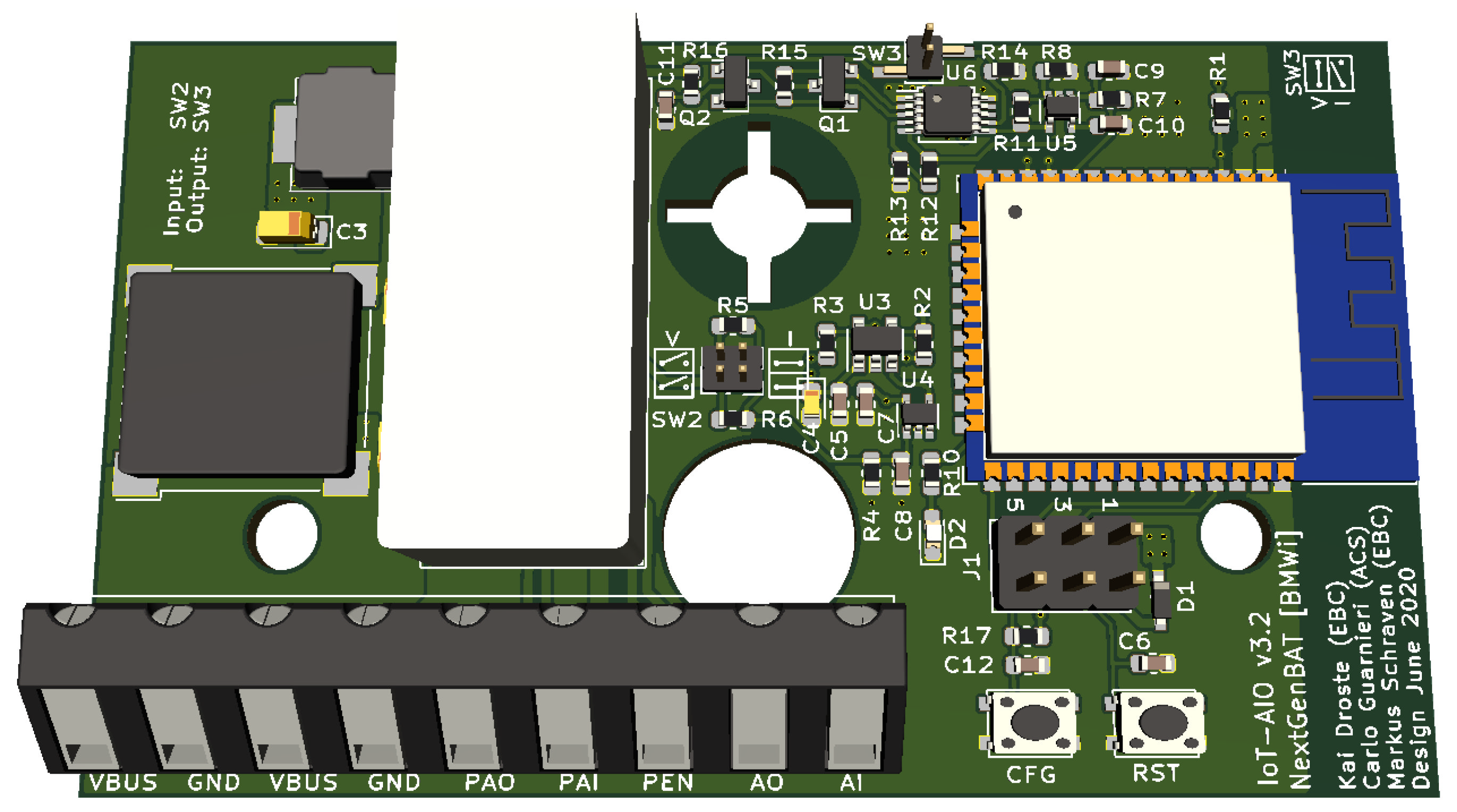
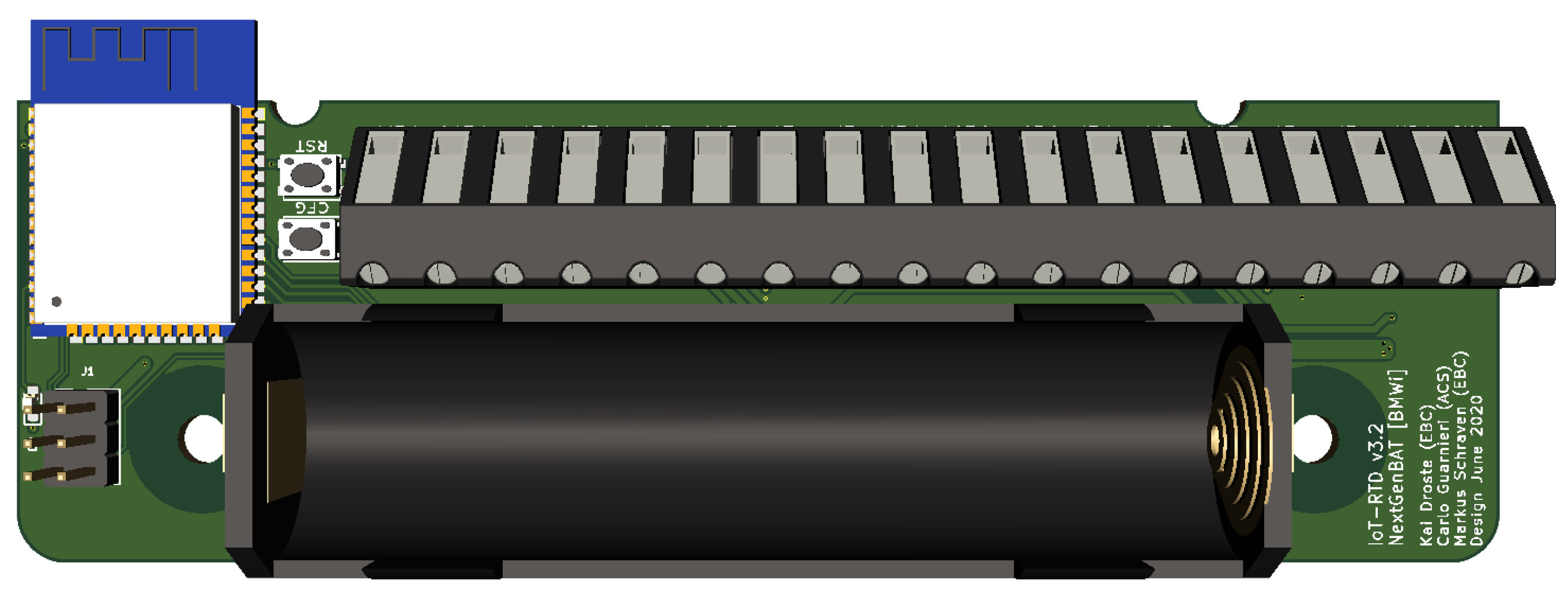
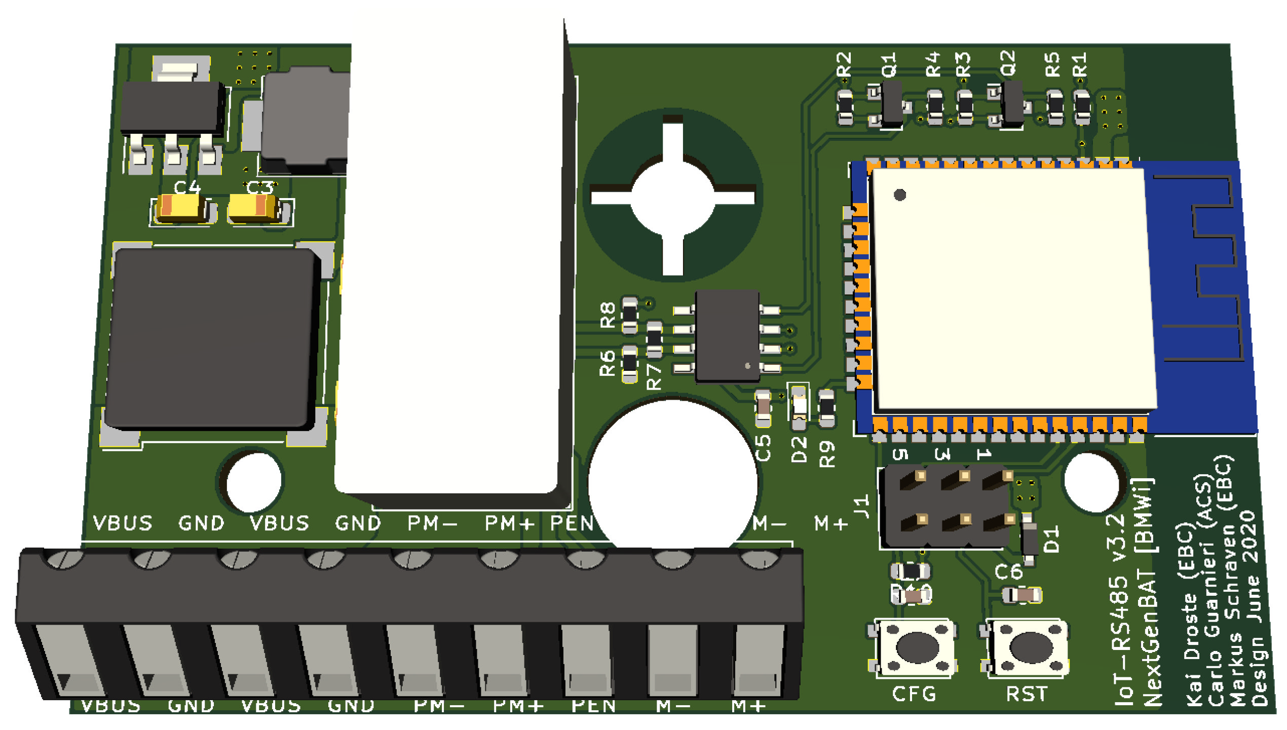
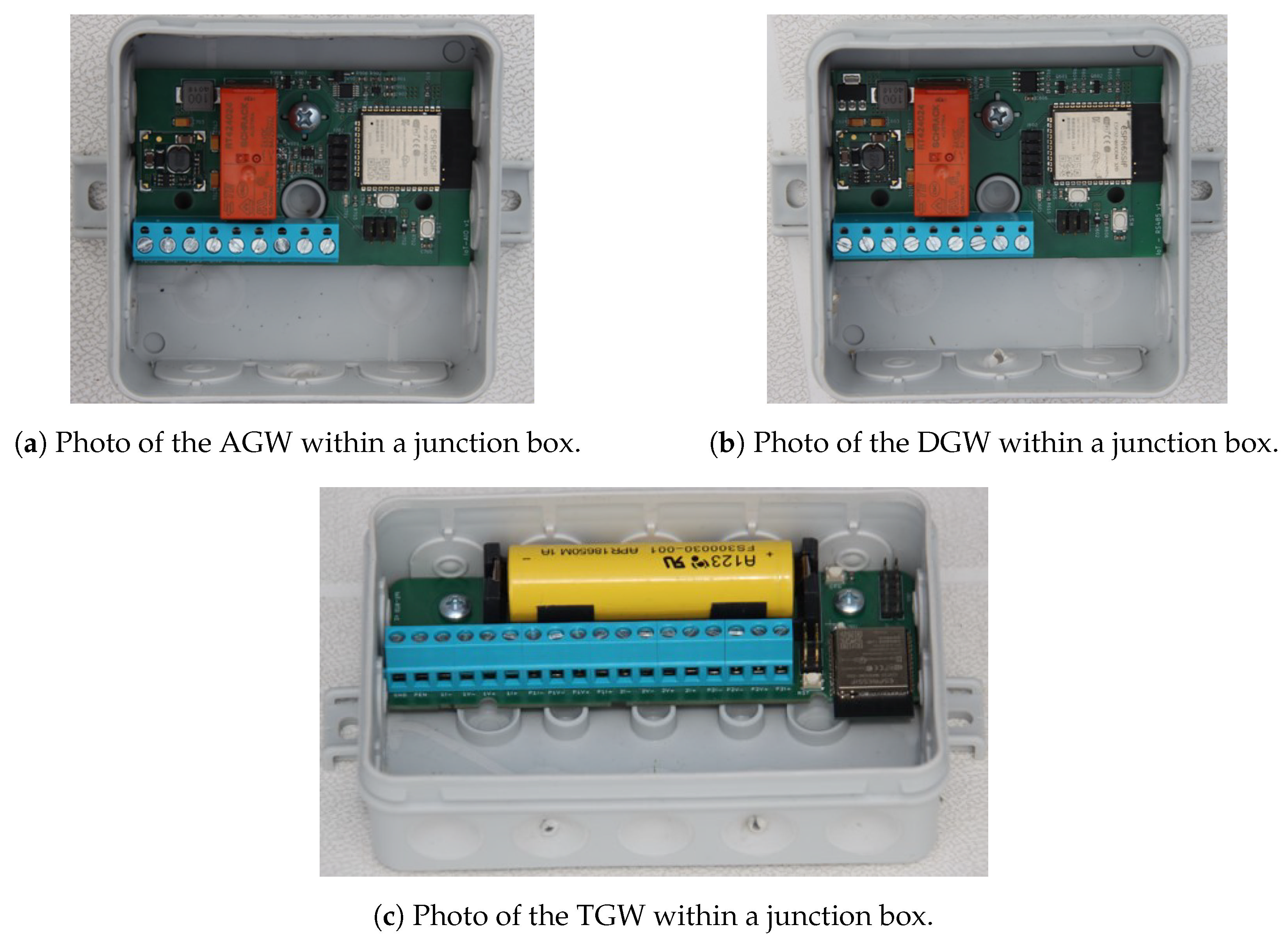
2.1.1. Hardware Design

The subsequent sections cover the PCB design and selected components to realize the specific interfaces. All three GWs were built around the Espressif ESP32-WROOM-32D [37] microcontroller as the main controller of the boards. While in previous works, a development kit, more specifically the ESP32-PICO-KIT V4, has been used, utilizing only the microcontroller chip offers the advantage of a completely automized assembly, which is a mandatory requirement for large-scale applications. Furthermore, this tackles the fact that the development kit caused the highest component cost in the previous design [30]. To deploy the firmware, instead of a micro USB port, an interface to an external USB to the transistor–transistor logic (TTL) universal asynchronous receiver–transmitter (UART) programmer, e.g., the ESP-PROG programmer, was used. As Espressif has designed the ESP32 specifically for IoT applications, it already offers built-in WiFi and Bluetooth® capabilities and also a wide range of different inputs and outputs. The selected ESP32-WROOM-32D provides an on-board PCB antenna for WiFi and 16 M of integrated serial peripheral interface (SPI) flash storage. Furthermore, the chip integrates several module interfaces such as UART, SPI, I2C, and pulse-width modulation (PWM) for communication with other modules. For further information on the available interfaces of the ESP32-WROOM-32D, refer to the data sheet [37].
As many sensor and actuator devices in BAS are specified with a 24 V DC power supply, a buck converter was used to transform the available 24 V DC input voltage to 3.3 V DC or 5 V DC to supply the ESP32 microcontroller and further components of the GW. An exception to this are passive RTD elements, which will be covered in the subsequent Section of the TGW design. Additionally, each GW was provided with a switching circuit that allows rerouting the input and output signals, thus providing backup capabilities in case of disturbed communication. More specifically, this circuit consists of a relay for the AGW and DGW and a multiplexer module for the TGW, which is triggered with a 24 V DC signal. In one configuration, the terminal ports are directly connected to the general-purpose inputs/outputs (GPIOs) of the ESP32, enabling internal processing of the signals, e.g., communicating to a cloud server. The second configuration loops the signals through the PCB, bypassing the ESP32. Accordingly, the latter configuration allows connecting to a legacy or backup system as a fallback solution.
The schematics and PCB design were created with KiCad 5.1.10.

Analog Gateway

The AGW was designed to support one analog input and one output signal, which, for instance, could represent a setpoint and a feedback signal of a simple motor actuator.
The AGW supports voltage and current mode, since analog devices are usually supplied with 0(2)–10 V over a short distance or, due to the voltage drop, over longer distances with 0(4)–20 m A . Each input and output can be set to run in voltage or current mode via header jumpers. Additionally, on a web server, the respective mode has to be adjusted (see Section 2.1.2). According to previous research experience, which demonstrated the limited performance of the embedded analog-to-digital converter (ADC) and digital-to-analog converter (DAC) of the ESP32 [31], the authors decided to use an external ADC for analog inputs and set the output voltage via pulse-density modulation (PDM) low-pass filtering to increase the accuracy for the AGW. The selected ADC was an MCP3021 with 10-bit resolution and an I2C interface for communication with the ESP32. This module has a lower resolution than the 12 bits of the internal ADC on the ESP32; however, since the internal ADC is coupled with the ESP32 reference voltage, an external module was expected to achieve more accurate and reliable measurements without additional calibration effort. For the analog output, the Texas Instruments XTR111 was used, as it has a high precision and offers a switchable current and voltage mode at an acceptable price.
A view of the AGW is depicted in Figure 1.

Temperature Gateway

The TGW was designed for passive RTD probes. To decrease the specific component costs, the TGW covers connections for two probes, since in BAS, temperatures often appear as pairs, e.g., to measure both supply and return temperature. Passive RTD probes are usually biased with a very small current and, therefore, do not require an additional power supply. To take advantage of this, a battery-powered operation was considered covering only the supply voltage of 3.3 V for the ESP32. The battery operation allows for a flexible application of the TGWs, as it only requires the RTD probe to be connected to the TGW. To reduce costs further, a battery management system (BMS) was not considered; thus, only batteries with a built-in safety circuit should be used to decrease the risk of explosion at deep discharging. In our applications, we used LiFePo4 cells with a 1000 m A h capacity.
The temperature measurement was realized by a MAX31865 RTD-to-digital converter. This converter has a 15-bit ADC resolution, resulting in an accuracy of approximately 0.03125   C . However, according to the data sheet, the resolution varies due to RTD non-linearity, yielding a total resolution over the full operational range of 0.5   C . The TGW supports applications with 2-, 3- and 4-wire RTD probes. To set up the TGW for a specific amount of wires, it is required to solder a zero Ohm resistor on the back of the PCB.
A view of the TGW is depicted in Figure 2.

Digital Gateway

According to the Modbus specification, for the serial line protocol Modbus RTU, a two-wire interface complying with the EIA/TIA-485 standard, also known as RS-485, should be implemented. The DGW utilizes the MAX13487 to convert between RS-485 differential signals and the common TTL UART interface for microcontrollers and peripheral parts (mostly resistors and capacitors) for the flow control, as the serial behavior allows either a request from the master or a reply by the slave. Using the MAX13487, on the hardware side, RS-485 communication is fully supported, which, aside from the Modbus RTU, serves as physical interface for further serial protocols such as BACnet MS/TP.
A view of the DGW is depicted in Figure 3.

2.1.2. Software and Configuration

The GWs’ operating system was FreeRTOS, and its firmware was developed in the C programming language utilizing the development framework ESP-IDF https://docs.espressif.com/projects/esp-idf/en/latest/esp32/get-started/index.html (accessed on 12 May 2022), which is provided by the manufacturer Espressif. Unlike ports to different programming languages, the ESP-IDF supports the full range of the ESP series’ functionalities. Furthermore, it is well documented and actively developed, and Espressif provides a minimum longevity commitment of twelve years—starting for the ESP32 in January 2016.
The firmware includes modules for the specific implementation of each interface, as well as, to name a few, modules for encrypted over-the-air (OTA) updates, time synchronization with a network time protocol (NTP) server, message queuing telemetry transport (MQTT) communication, JavaScript Object Notation (JSON) parsing, and a web service for the user to configure related parameters. While the digitization of signals is achieved by the corresponding integrated circuit components in the previous Section 2.1.1, the digital data transport is even more flexible, e.g., basically, all IoT protocols building on the WiFi or Bluetooth® network architecture can be utilized. In this study, we chose MQTT for the digital data transfer, as it is one of the most-popular protocols in IoT applications [38], and WiFi as the preferred radio transport. As MQTT is data-agnostic, JSON parsing was used for the specific message format.
For an easy configuration, a WiFi access point mode was included, allowing a GW to create its own WiFi network to which a technician can connect his/her laptop or smartphone to access the configuration web service. More specifically, the configuration allows for specifying:
  • The SSID and password for WiFi connection;
  • The broker address, credentials, and message format for MQTT communication;
  • Auto-configuration when using the FIWARE platform;
  • Time synchronization and the respective NTP server address;
  • Data point identifiers, data transmission mode (periodic, change of value (COV)), and interval or threshold;
  • For the AGW: setting of the voltage or current mode, the live-zero signal, and a customizable scaling;
  • For the TGW: the sensor type, valid operational range, and number of wires (2-, 3-, 4-wire);
  • For the DGW: the Modbus parameters and registers (the BACnet implementation is currently still under development).

2.1.3. Summary

A summary of the specifications for the developed GWs is presented in Table 1. Three different GWs were developed: one for analog communication, one for integrating passive RTD probes, and one covering serial communication via RS-485. The main component is the ESP32 microcontroller by Espressif. It natively supports WiFi connection with IPv4 and IPv6. Table 1 contains the most-relevant components used for signal conversion between conventional interfaces and the ESP32 microcontroller. As an important addition, all GWs support a switching mechanism, enabling backup capabilities in case of disturbed communication. Furthermore, IoT communication was realized by MQTT with the JSON message format. The firmware was developed using the C programming language and the ESP-IDF provided by the manufacturer. Besides the specific interface implementation, the firmware adds a web service for users to configure Internet and message broker connection. All schematics, PCB designs, and the firmware are provided under the MIT license [33]. Additionally, the repository contains a quick start guide and further documentation for application and development.

2.2. Performance Analysis

To justify the viability for industrial-like applications, a performance analysis was conducted. The performance analysis was divided into two sections covering experiments for the AGW and the TGW. The goal was to compare the collected measurements with a conventional programmable logic controller (PLC), which is often used in BAS. In this study, a commercial Beckhoff® CX5130 was used. Accordingly, the applied software to operate the PLC was TwinCAT®3 by Beckhoff®. For the DGW, the same components were used as in the previous work [30]; therefore, a new analysis was not expected to reveal any new results.

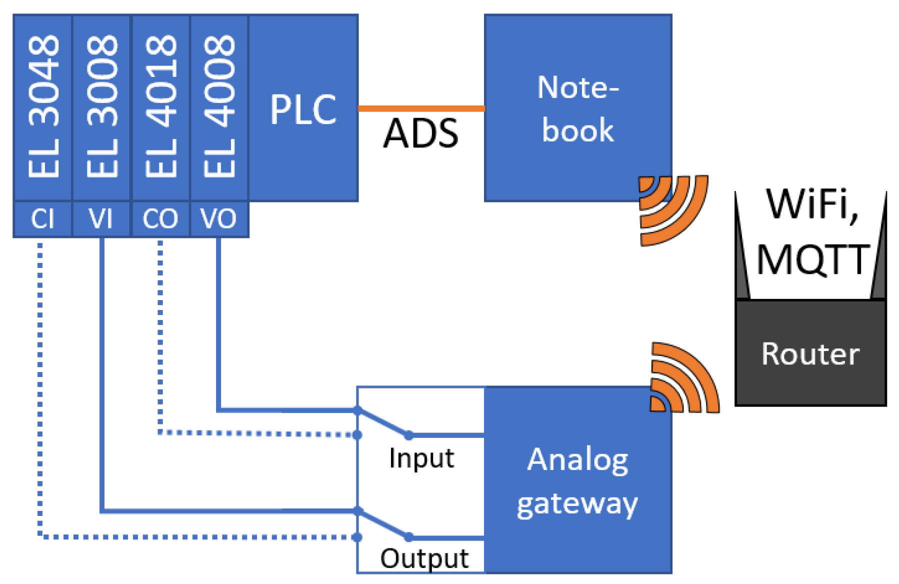
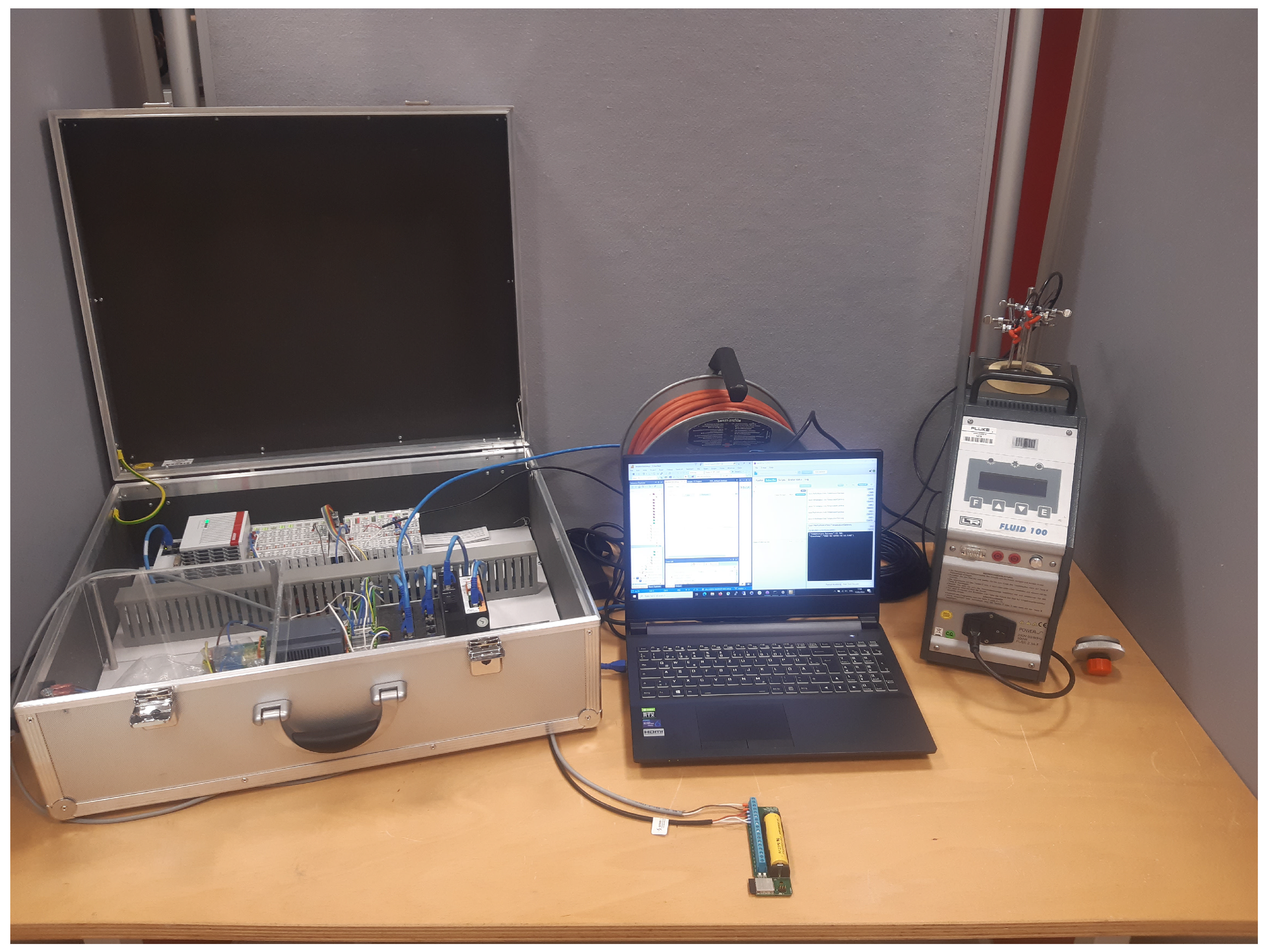
2.2.1. General Setup

For the performance test of the AGW and TGW, both GWs were compared to measurements from a PLC. To simplify the data acquisition, the GWs were connected to a local Mosquitto broker running on a notebook within the same network, whereas the PLC was locally connected to the same notebook and sent its values via the vendor-specific automation design specification (ADS) interface. The GWs were connected via WiFi and using the MQTT protocol. Whenever a GW sends a value to the broker, a Python script running on the notebook receives this value due to a subscription to the broker and immediately fetches the value from the PLC using the pyads module. The PLC communication was based on an implementation of an ADS-MQTT-interface in the AixOCAT library [39] (https://github.com/RWTH-EBC/AixOCAT), and the connection was realized with a direct Ethernet link to a LAN port of the notebook. However, only the ADS part was used for fetching the data from the PLC. Subsequently, the current timestamp and both GW and PLC-related values are written to a .csv file on the notebook (alternatively, both the GWs and the PLC (Using the ADS-MQTT-interface) could be connected to a cloud-hosted database, e.g., in our projects, we often use the FIWARE platform [32] or aedifion [40]. Data are then usually stored in efficient time series databases and receive a timestamp directly from the platform upon data acquisition.). The data transmission rate of the GWs was set to 1 s . The corresponding Python scripts and data acquired are published within the same repository as the schematics, PCB designs, and firmware [33].

2.2.2. Analog Gateway Performance

The AGW was validated for its specific voltage and current range from 0–10 V and 0–20 m A by directly connecting the AGW terminals to the PLC terminals.
Figure 4 depicts a schematic view of the experimental setup for the performance analysis of the AGW, where the terminals on the AGW connect to the respective terminals on the PLC. The performance analysis was conducted in two stages: First, the AGW was set to voltage mode, and accordingly, the voltage terminals of the PLC were used. Subsequently, the AGW was switched to current mode and, by analogy, connected to the respective current terminals on the PLC. On the PLC, four different terminals from Beckhoff® were used, each specified with a resolution of 12. More specifically, the EL3008 represents a voltage input terminal and the EL3048 a current input terminal, both given with an input error of 0.3 %. On the other hand, the EL4008 terminal was used for voltage output and the EL4018 terminal for the current output. Both output terminals were specified with an error of 0.1 %. Accordingly, the output ports on the AGW were connected with the input terminals on the PLC and vice versa.
The PLC was used as the reference for the voltage and current levels. For the input test of the AGW, the PLC output value was varied between 0–10 V in 1 V steps for the voltage and 0–20 m A in 2 m A steps for the current, and the input voltage or current was measured by the AGW. For each step, the measurement period amounted to 200 s , corresponding to 200 samples at a 1 Hz sample rate. The output test of the AGW was performed analogously to the input test. Hence, the value was set on the AGW and measured by the input terminals of the PLC.

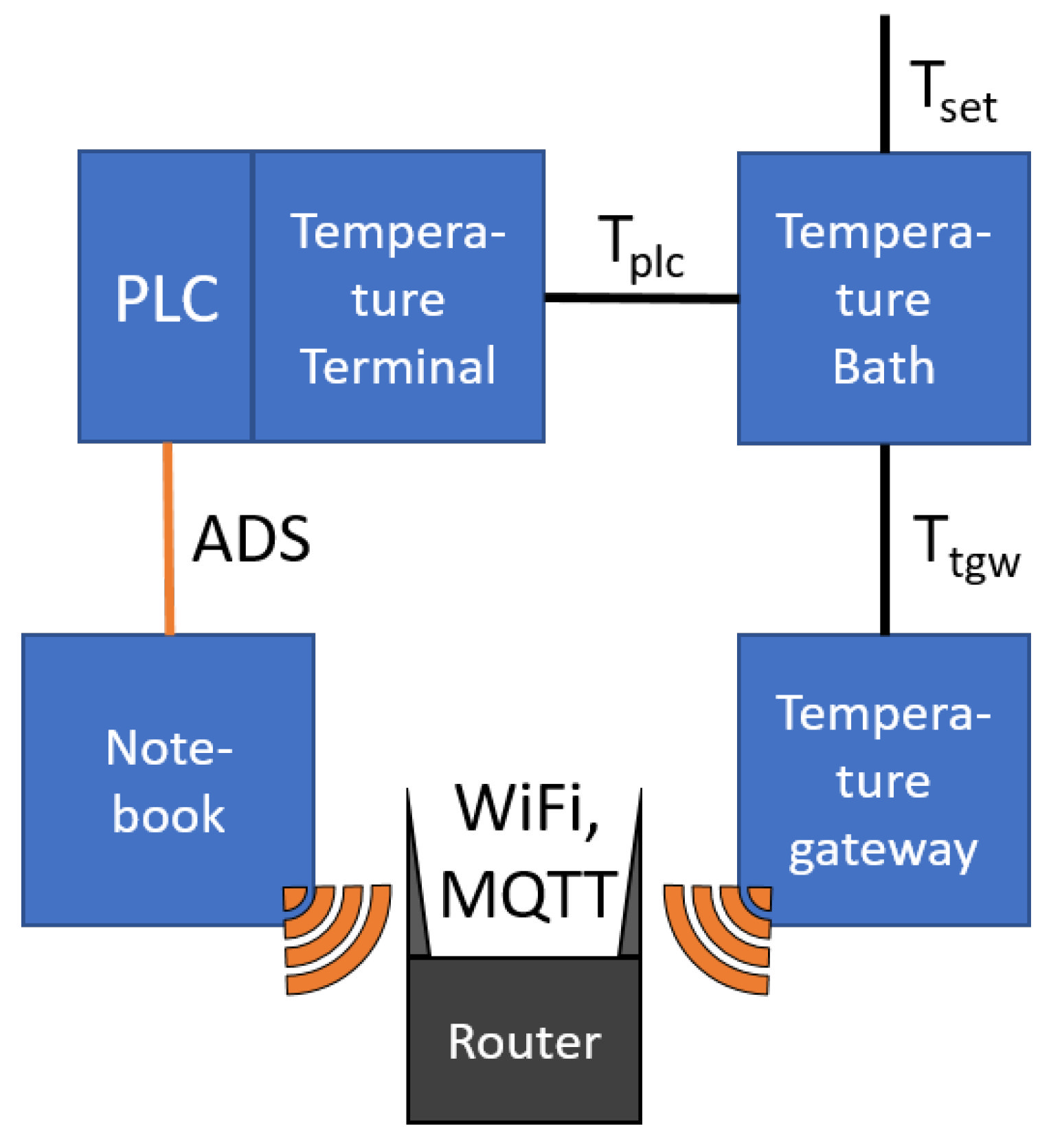
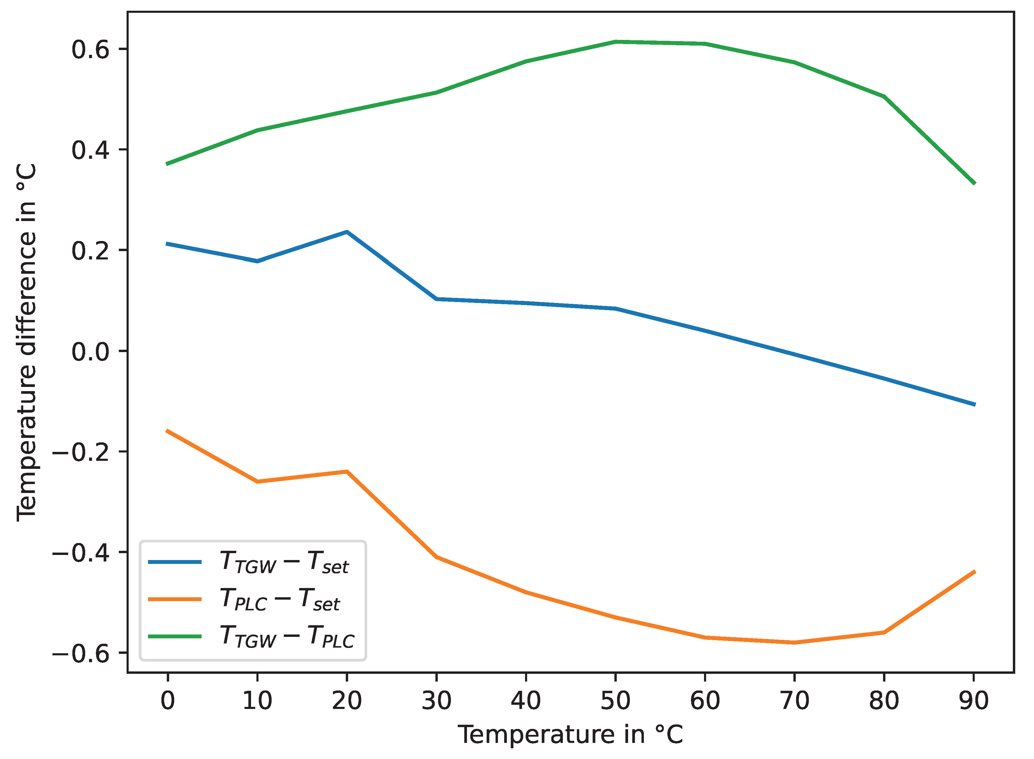
2.2.3. Temperature Gateway Performance

The TGW was validated for a wide temperature range using a temperature bath and compared with the measurement from a PLC.
Figure 5 depicts a schematic view of the experimental setup for the performance analysis of the TGW. Both the PLC and temperature GW were connected to a 4-wire PT100 temperature sensor with class 1/3 DIN accuracy. On the PLC, the terminal EL3202-0020 from Beckhoff® was used, which was specified with a 0.01   C resolution and a ± 0.1   C accuracy. The temperature bath was an LR-Cal FLUID 100, which allowed setting the temperature of the thermal oil in a range of −12   C to 125 C . In the experiment, the temperature was varied from 0 C to 90 C in 10 C steps, which covers most applications in BAS (As audit documents are rarely shared, compare, for example, the development in district heating and cooling networks’ temperature levels [41,42]. Using boilers or combined heat and power as the primary heating source will keep producing high temperature levels). Each setpoint was held for 600 s after the temperature bath reported a steady-state condition, corresponding to 600 samples at a 1 Hz sample rate.
The data acquisition was set up similarly to the AGW’s performance analysis, as described in Section 2.2.1. By analogy, whenever the broker reports an incoming measurement, both temperature values and the current timestamp are written to a .csv file. The complete setup is shown in the real application in Figure 6.

3. Results

3.1. Cost Distribution

Table 2 shows the cost distribution of the three different GWs over the PCB, the component cost, and the assembly cost. All parts and services were ordered from a European manufacturer. The costs for the PCB depend on the size of the board. Hence, the TGW is more expensive, since it needs more room for the battery holder. Furthermore, the development costs depend on the number of different components. The TGW resulted in the highest costs at EUR 53.32; however, it allows connecting two RTD probes. AGW and DGW required similar costs of EUR 36.07 and EUR 31.67, respectively.

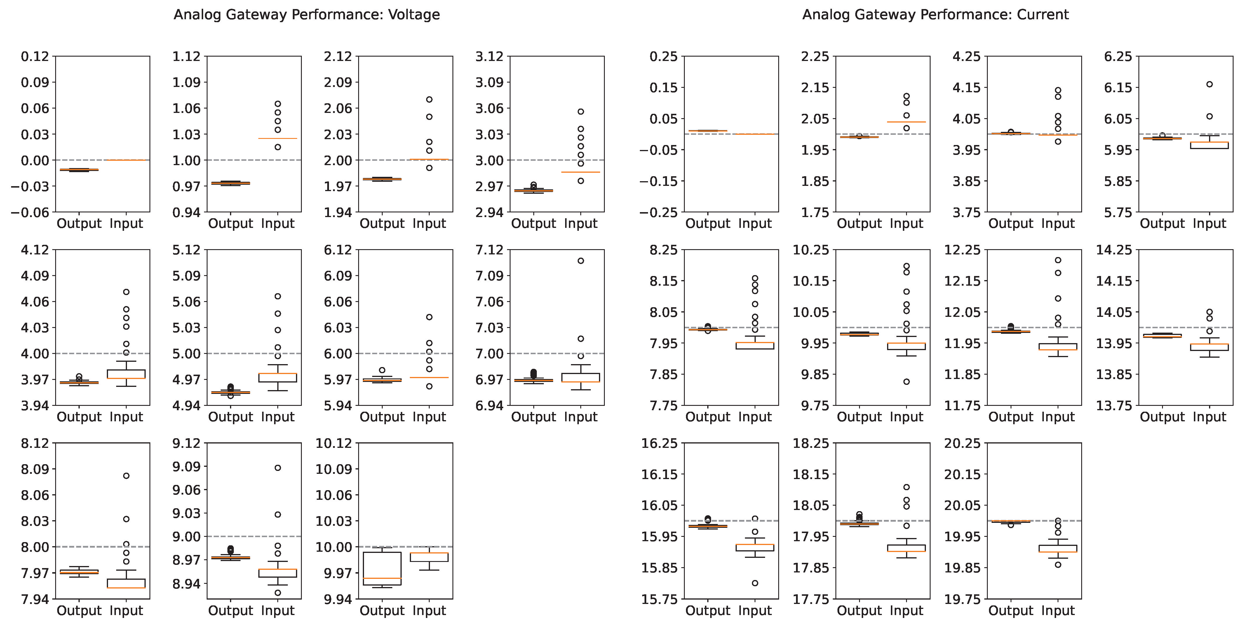
3.2. Results of the Analog Gateway’s Performance

In Figure 7, the results of the analog performance test are summarized as boxplots with the box defaulting to the first and third quartile and the whiskers extending from the box by 1.5× the inter-quartile range. The related set voltage and current values for the tests are displayed as gray dashed lines.
The average deviation for the voltage operation from the reference amounted to 0.016 V on the voltage input and 0.03 V on the output. For comparison, in the previous development stage, the average performance was determined to be 0.11 V on the input and 0.12 V on the output section [30]. Hence, the performance of the voltage interfaces could be increased by over 75%, justifying the usage of the external ADC and PWM over the previous implementation. Furthermore, the maximum deviation for the input voltage decreased to 0.107 V and for the output to 0.04 V ( 0.75 V and 0.29 V in [30]). The current interfaces could be improved as well with a mean deviation of 0.042 m A for the input and 0.009 m A for the output, respectively ( 0.22 m A and 0.21 m A in [30]). The maximum deviations for the current interfaces amounted to 0.216 m A and 0.021 m A .
The maximum relative deviation barely reached about 7% due to some outliers at the 1 V set voltage. Over all measurements, the output interfaces showed very small quartile bands, suggesting a reliable operation, especially in terms of the repeatability. The input boxplots show considerably more outliers than the results from the output, suggesting noise in the measurement chain, which utilizes the external ADC. This noise can be the result of a direct coupling of external noise sources on the signal wires or, rather, due to internal noise affecting the ADC voltage reference. Moreover, the input values for the current and voltage test did not exceed the minimum and maximum range of the tests for 0 and 10 V and 0 and 20 m A . These limits resulted from the operational range set in the firmware, which did not allow any measurements outside the given range to be sent to the broker.

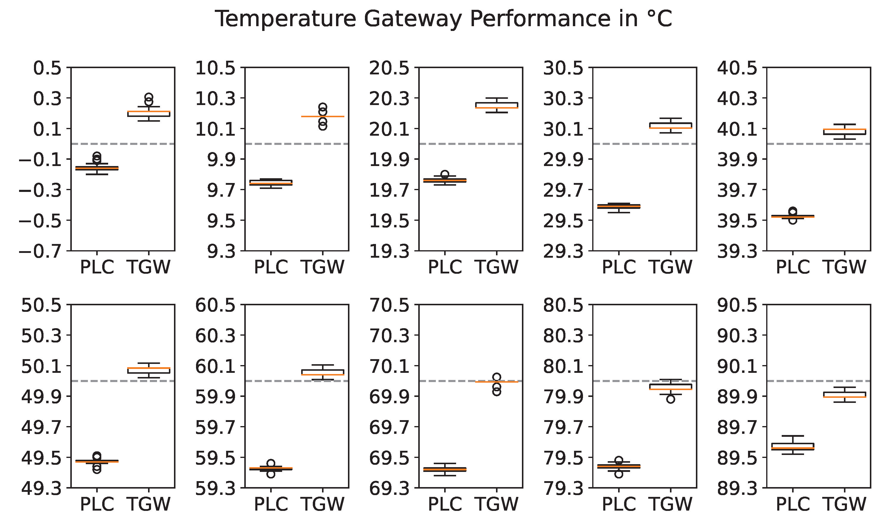
3.3. Results of the Temperature Gateway Performance

In Figure 8, the results of the temperature performance test are summarized as boxplots with the box defaulting to the first and third quartile and the whiskers extending from the box by 1.5× the inter-quartile range. The related set temperatures for the temperature bath are displayed as gray dashed lines.
With rising temperature up to 70 C , the TGW showed a decreasing deviation from the set temperature. However, note that the internal temperature from the temperature bath was not calibrated, and the instructions suggest using an external reference. The deviation of the TGW and PLC median temperature increased from 0.372 C at 0 C to a maximum of 0.614 C at 50 C and decreased again from there to a minimum of 0.334 C at 90 C . For the most part, the PLC showed a much smaller quartile band than the TGW. This effect was presumably caused by the much higher resolution of the PLC compared to the TGW, causing the TGW to register higher deviations from the median value, which added up to a larger quartile range. The average deviation over the full range including all measurements amounted to 0.535 C , which can be assumed sufficient for most building automation applications, especially since they usually do not rely on an absolute reference, but rather, operate with relative or differential measurements.

4. Discussion

The total costs of the previous design were estimated to be about EUR 28 [30]. However, in the previous study, the costs for the assembly and PCB were not taken into account. Even with the addition of the switching mechanism, requiring additional components, the component costs could be reduced by about 27% to 41% for the AGW and DGW being separated and picking the ESP32 chip over the development board. Note that the AGW, DGW, and TGW were ordered individually and at different quantities. Therefore, ordering the required GWs for a specific application, the overall costs could be reduced further by higher quantities and a summarized order, e.g., obtaining the single PCBs from a panel. Yet, the component costs remained the highest share of the total costs.
Overall, the TGW induced the highest costs. Due to the battery tray, the PCB has larger dimensions, resulting in more than double the PCB costs as for AGW and DGW. During the experiments, the battery operation proved to be practical; however, with a capacity of 1000 m A h , the battery lasted for a duration of only 2 d to 3 d, making it hardly useful for actual applications. Further analysis of the individual components is required to detect why the TGW seemed to drain this unanticipated amount of energy. An alternative 24 V DC power supply can be added, for instance, using a buck converter, which is described in the manual [33]. If a 24 V DC power supply were used, the PCB dimensions could be reduced to decrease the overall costs of the TGW. Considering the total costs, in the case of battery operation, the addition of a BMS would only add them up marginally, but would solve the issue that, for an empty battery, the switching mechanism via the multiplexers would not work, as they require a permanent supply to operate. Therefore, both a smaller version with a 24 V DC power supply, as well as a battery-operated version with an additional BMS should be addressed in the future. Furthermore, a detailed component analysis is required to further investigate the unanticipated power drain.
In comparison to the PLC and the respective terminals used in the performance analysis, the GWs achieved a noticeable cost advantage, as can be derived from Table 3.
For instance, 8 AGWs at a price of 8 × 36.07 = E U R 288.56 would offer the same number of connections as 1 EL3008 and 1 EL4008 at EUR 333.00, not including the required PLC for processing and the backup capabilities of the GWs. In the case of temperature measurement, the EL3202 offers the same amount of connections as the TGW at considerably higher expense. In addition to the PLC itself, a CFast card with 3D flash, for instance, in the described setup, a 30 G card was used at a price point of EUR 180, as well as a license for the software operating the PLC is required. In the case of the Beckhoff® components, the software license costs heavily depend on the performance class of the PLC. In this case, the TwinCAT®3 software at performance class 40 requires the TC1200-0040 license, resulting in an additional EUR 75 (for comparison: The TwinCAT®3 license costs at performance class 80 TC1200-0080 amount to EUR 375). Furthermore, the connection in the IoT context requires additional engineering for the PLC.
On the upside, the PLC terminals are specified with higher resolution and measurement accuracy (compare Table 3). While the TGW measurement performance is acceptable for most applications in BAS, it might not be sufficient for specific scientific studies, where higher measurement accuracy is desired. At this stage, the resistance to temperature conversion was implemented using the Callendar–Van Dusen equation, truncating after the second-order term. If higher accuracy is required over the extended range, it might be worth implementing a recursive solution by the minimization of the original third-order equation, which would be addressed in the further firmware development. On the other hand, the PLC requires a specific terminal to connect 4-wire temperature probes, while the TGW is more flexible, supporting 2- to 4-wire configurations with limited soldering effort, but without requiring additional components. Another advantage is the decentralized usage of the TGWs, allowing for shorter cable lengths, which might enable more applications based on a two-wire configuration due to the lower accuracy losses. Overall, the TGW offers a sufficient trade-off among flexible usage, costs, and accuracy. A further aspect to look at is a user-defined calibration, where the PLC already offers options to customize the measurement data with the offset, slope, and filters. These kinds of options are not yet implemented for the TGW, but should be considered for future applications.
One limitation of this study is that the PLC does not represent an absolute reference. In order to perform a precise evaluation, a certified test procedure in a clearly defined encapsulated environment and with calibrated high-precision devices is required, which follows the principals of the DIN EN ISO 17025 standard. For instance, Beckhoff® offers their terminals in three different variations, e.g., standard, factory-calibrated, and externally calibrated variants. According to Beckhoff®, the provided measurement accuracy in their data sheets is a maximum limitation, and the actual deviations are usually much lower. External evaluations are offered by accreditation bodies such as the Deutsche Akkreditierungsstelle GmbH (DAkkS). In our study, we used the PLC as the reference for voltage and current input and output signals, in particular because neither a calibrated high-precision voltage and current source and measurement instruments, nor an adequate environment were available to meet the principals of the DIN EN ISO 17025. However, as the PLC represents the benchmark, the deviation between the measurements of the GWs and of the PLC is considered to conform to an adequate measurement performance evaluation.
Similarly, because the temperature bath is not a certified high-precision device, we rather evaluated the deviation from the PLC measurements as our benchmark. The effects became more obvious when observing in detail the development of the deviations with the set temperature of the temperature bath. In Figure 9, the blue and orange curves represent the median deviations between TGW and the set temperature or the PLC and the set temperature, respectively, and the green line corresponds to the median temperature difference of the TGW and PLC over the set temperatures for the temperature bath. In the analysis, the temperature point granularity was chosen to 10 C , and due to the assumed linear behavior of the Pt100 sensor element, e.g., the Pt100 element is considered to have a linear relationship between temperature and resistance, it is expected that intermediate points can be obtained by interpolation. The temperature point granularity is further supported by the Physikalisch-Technische Bundesanstalt (PTB), suggesting at least three different temperatures (calibration points), which are distributed as evenly as possible over the desired operating range of application [43]. In fact, as illustrated in Figure 9, at a set temperature of 20 C , the temperature differences deviated significantly from an interpolated value between 10 C and 30 C . However, this anomaly was detected in both the PLC and TGW measurements and, thus, is most likely an issue with the reference temperature or, rather, the resulting temperature of the temperature bath control.
Another limitation is that the measurement performance of only one GW for each type was evaluated. Although several samples were recorded and GWs of the same type share the same architecture, differences may occur for different GWs of the same type. Therefore, further analyses should be conducted in the future to obtain a full specification of the performance, for instance including long-term stability, etc. In this regard, the performance analysis should be extended as well to develop a standardized measurement procedure. These additions, however, are beyond the scope of this study.
Comparisons with commercial products are hardly possible due to differing functionalities, proprietary communication, or still missing prices for new innovations. One example for a smart valve actuator handling the operation of the valve position and communication is the Comparato Diamant Smart Pro [44] at roughly EUR 600; another one, the Aranet PT100 transmitter [45], represents a radio-based RTD sensor at prices between EUR 200 and 300.
These examples show the potential of the presented solution. However, the GWs have not yet undergone any certification process. Developing the GWs into an actual product will have several implications, influencing their price-performance ratio, e.g., certification, additional security measures such as trusted platform modules, supply chains, production lines, etc: As can be seen in Table 3, all PLC components, as well as the GWs have a degree of protection of only IP20; thus, for installation, an enclosure is required. Depending on the number of connected terminals, PLCs and their components are usually mounted to a top-hat rail in mid-size or large control cabinets, causing additional expenses of EUR 200 and more [46]. In fact, due to the decentralized operation of the GWs and as a cost-efficient solution, the use of junction boxes has been considered as the enclosure. Therefore, the PCBs have mounting holes drilled specifically to fit to the junction boxes Spelsberg 2K-12 AB-L for AGW [47] and DGW and Spelsberg 2K-16 AB-L for the TGW [48] (see Figure 10). As junction boxes are basic components in electrical installations, they represent a highly available and less-expensive solution than housings specifically designed for the PCBs or 3D-printed ones. The Spelsberg junction boxes are specified for indoor installations with a degree of protection of IP55, and the specific costs for 90 pcs. 2K-12 AB-L and 20 pcs. 2K-16 AB-L ordered in 2020 were EUR 0.9515 and EUR 1.683, respectively. Among others, the most relevant directives to consider for placing a product in the European market is the CE marking including electromagnetic compatibility (EMC), low voltage directive (LVD), radio equipment directive (RED), restriction of certain hazardous substances (RoHS), waste of electrical and electronic equipment (WEEE) [49], and possibly further. However, with a maximum voltage of 24 V DC, the GWs are not considered as electrical equipment according to LVD, and further simplifications may apply. Nonetheless, the certification process involves much effort and expense, and the costs may vary between a couple hundred and several tens of thousands of EUR [50].
Note that the costs for the research and development (R&D) of the schematics and firmware were not included in the GW costs. As all relevant files are released under the MIT license, these costs do not need to be considered by the users. Therefore, additional costs only apply, if users intend to develop the given solution into a commercial product, if a use-case entails specific requirements, and hence adjustments, or for developing further enhancements. To put the invested resources for the current development state into perspective, the project has been carried out by mainly three persons starting from mid-2018 and a share of about 15% to 20% of the working time. Considering an average of 1700 h / yr −1, roughly 3300 h have been spent working on this project. However, this is hardly comparable with a company having several employees in different departments such as R&D, software development, hardware design, quality control, testing, etc.
Accordingly, commercial products from companies with continuous development over several years are considered to have higher reliability due to experiences and runtime statistics in various applications. So far, the GWs have been particularly applied in two projects: firstly, in the Master’s thesis of Droste [51] and, secondly, in a project thesis of Block and Dunkel [52]. In [51], Droste compared the control behavior in a cloud control scenario with the local control of a PLC in a BAS subsystem. During a runtime of about two weeks of experiments, no issues were found in the operation of the GWs. Block and Dunkel extended these experiments to a specific test stand representing a part of a typical BAS. While in [52], again during a duration of about two weeks of experiments, many disturbances occurred, the majority of them could not be related to the malfunctions of the GWs, but were rather caused by the cloud setup. The developed test stand in [52] has also been exhibited at the HANNOVER MESSE 2022, which took place 7 months after the thesis was finished. Over all applications during the past two years, only two GWs were found to have a major malfunction, which, however, could be traced back to operational errors caused by the user. A minor issue has been discovered in the time stability and synchronization, where different GWs’ timestamps would vary significantly even with hourly NTP synchronization. This effect was found to be more relevant for the AGW, in particular when receiving control signals at high frequencies, e.g., 200 m s ; however, this does not impede the operation.
Another aspect to take into account is the wireless connection. Using the ESP32-WROOM-32D chip and its onboard antenna, the GWs rely on the WiFi architecture and the corresponding properties. In [51], a maximum distance between the GW and the WiFi router of about 15 m including a 150 m m concrete ceiling still yielded a sufficient signal strength for a reliable operation. Higher signal strengths could be achieved, using the ESP32-WROOM-32U instead, as it supports a port for connecting an external antenna with higher gain. The architecture in [52] included the connection from the access point to the Internet being realized with Long-Term Evolution (LTE). Besides the LTE connection being heavily dependent on the location, here, the throughput may be limited. Again, the AGW is affected most, if high frequent control signals are applied. Therefore, in an application with 60 data points at a 1 Hz transmission and control signals at roughly 5 Hz , an increased packet loss was observed, causing further issues in the cloud setup.
The wireless communication via MQTT supports Transport Layer Security (TLS) to encrypt and, thus, secure the data transfer. Other than that, the GWs are connected to a WiFi access point and, consequently, only accessible from within the same network or by physical access to the GW for the initial configuration and connection. The network does not necessarily need to be connected to the Internet, but can also be operated as a local network connecting the GWs to a local server. Due to the decentralized architecture, each GW should be configured with individual credentials for maximum security [53]. This way, the GWs will not represent a single point of failure in case of an intrusion attack. Compared to conventional BAS, the communication security is not necessarily lower, since, in particular, serial bus communication such as the Modbus RTU or BACnet MS/TP offers no security whatsoever and not all IP-based building networks are whitelisted, e.g., allowing only devices of registered MAC addresses to connect. Security in conventional BAS communication has especially been addressed in the development of the BACnet secure connect (SC) standard [54].
As introduced in Section 1, the majority of research activities focus on developing alternative measurement solutions. These often refer to room automation in order to estimate the indoor air quality of occupants and adjust the control in accordance with the demand. Even though the GWs were developed targeting BAS applications, due to their quite general signal conversion, their application is not limited to BAS and could be extended to different domains. However, the presented GWs were not designed for the data acquisition of several measured quantities at one location. In order to tackle this sort of application, a specific individual GW would be useful and will be addressed in the future development. A key requirement is again the scalability, e.g., deploying the solution in several rooms and a comparable measurement performance as conventional measurement systems in room automation and indoor air quality estimation. While the DGW allows for the data acquisition of multiple devices connected in a bus network, it is currently restricted by the firmware, which only allows specifying one device in the configuration interface. This restriction has been given, in particular, due to no structured approach being specified to scan the network and read properties in a specific order and without a high manual effort in specifying all readings individually. Therefore, an evaluation of the DGW scaling when reading data from multiple devices in a bus network is yet to be performed. Besides this, the DGW so far only has the Modbus RTU communication implemented, while the BACnet MS/TP could not be implemented due the lack of resources.
Referring to the configuration, it was stated that this step could be performed without any programming skills. While this is true, it requires the GWs to include the firmware so that the web interface is available. The firmware has to be flashed onto the GWs using a programmer such as the ESP-PROG and may require some understanding about the ESP-IDF and the ESP32 chip. Additionally, any adjustments to the firmware or the web interface will require advanced programming skills in C and basic knowledge of HTML. In order to distinguish these different groups of occupations, e.g., technician, supplier/preparer, and developer, the training material has been sectioned to tackle the specific requirements and steps [33].
Finally, another interesting addition is the inclusion of embedded or tiny machine learning in order to realize a sophisticated distributed local control.

5. Conclusions

Due to a variety of existing interfaces in BAS, the integration of the IoT remains a challenging task. While many commercially available solutions integrating the IoT in BAS rather focus on closed access with limited configuration options, solutions in research seldom exceed a proof-of-concept stage and, due to their DIY character, are not suitable for industrial applications such as building automation. In this work, we proposed some open-source IoT GWs for building automation applications. In fact, the most cost- and resource-efficient approach is the direct integration of IoT capabilities with the sensor and actuator components, and thus, GWs represent a preliminary stage. Following this approach, the presented GWs were distributed over three types of interfaces, more specifically a TGW for passive RTDs, an AGW, and a DGW for bus communication via RS-485. In addition to the provided hardware interfaces, the firmware includes a web service for an easy configuration of the Internet connection, broker specification, including security and payload format, data transmission customization, time synchronization, and calibration. Furthermore, OTA updates of the firmware and—when using the FIWARE platform—an auto-configuration from the cloud are supported. All schematics, PCB designs, and the firmware are provided under the MIT license [33], giving users the opportunity to easily obtain, use, customize, or develop their own GWs for their applications. Furthermore, this allows for a fully automized manufacturing, which is mandatory for large-scale applications. Aside from that, all data acquired in this study, as well as the related scripts are available in the same repository.
To prove the applicability in industrial applications, a performance analysis was conducted comparing the measurements of the GWs with those from a PLC, which is commonly used in BAS. Over all measurements, the maximum deviation between the AGW and the reference values measured or set by the PLC amounted to 0.216 m A for the current interface and 0.107 V for the voltage interface or, on average, 0.042 m A and 0.03 V , respectively. In comparison with the previous development stage, the performance could be increased by over 75%, while reducing the component cost by roughly 30%. For the TGW, the maximum deviation to the PLC measurement occurred at 50 C and accounted for 0.614 C , while the average deviation of the full range of measurements accounted for 0.535 C . The costs amounted to roughly EUR 53 for the TGW covering connections for two temperature probes, EUR 36 for the AGW including a single-ended input and output connection for devices such as simple electric valve actuators, and EUR 32 for the DGW. Compared to the previous design, the component costs could be reduced by about 27% to 41% for the AGW and DGW being separated and picking the ESP32 chip over the development board. Hence, overall, the performance analysis suggested an acceptable trade-off among the costs, performance, and flexibility of the proposed GWs. With the given accuracies, the GWs are well suited for operation in BAS, and as the interfaces are generally common for sensors and actuators, the applications are not limited to the building domain. Compared with commercially available solutions such as the Aranet PT100 Transmitter or the Comparato Diamant Smart Pro, the GWs achieved significantly lower costs at a comparable or even higher range of functions and higher flexibility [44,45]; however, they do not include a certification and a warranty.
The future perspectives include:
  • Targeting open issues with the battery operation of the TGW;
  • Improving the user experience, handling, and functionalities of the configuration in practical applications;
  • The development of an individual specific GW, targeting environmental measurements for room automation and indoor air quality estimation, following the requirements for a scalable and accurate solution;
  • The addition of embedded machine learning models to allow for sophisticated distributed local control.
Following the open-source approach, we encourage and support participation in further development.

Author Contributions

Conceptualization, M.H.S. and C.G.C.C.; methodology, M.H.S. and K.D.; software, K.D., M.H.S. and C.G.C.C.; validation, M.H.S. and K.D.; formal analysis, M.H.S.; investigation, M.H.S. and K.D.; resources, M.H.S.; data curation, M.H.S. and K.D.; writing—original draft preparation, M.H.S. and K.D.; writing—review and editing, C.G.C.C., D.M. and A.M.; visualization, M.H.S. and K.D.; supervision, D.M. and A.M.; project administration, M.H.S.; funding acquisition, D.M. All authors have read and agreed to the published version of the manuscript.

Funding

This research was funded by the Federal Ministry for Economic Affairs and Climate Action (BMWK) Grant Numbers 03ET1657A and 03EWR020E.

Institutional Review Board Statement

Not applicable.

Informed Consent Statement

Not applicable.

Data Availability Statement

All materials to recreate the presented results, e.g., the PCB designs to obtain the GW hardware, the related firmware, a documentation and instructions manual, as well as specific scripts for the experimental study and the obtained data, are openly available at https://github.com/RWTH-EBC/OSIGBApp (accessed on 26 October 2022).

Conflicts of Interest

The authors declare no conflict of interest. The funders had no role in the design of the study; in the collection, analyses, or interpretation of the data; in the writing of the manuscript; nor in the decision to publish the results.

Abbreviations

The following abbreviations are used in this manuscript:
ADC    analog-to-digital converter
ADSautomation design specification
AGWanalog gateway
BASbuilding automation system
BMSbattery management system
COVchange of value
DACdigital-to-analog converter
DGWdigital gateway
DIYdo-it-yourself
EMCelectromagnetic compatibility
GPIOgeneral-purpose input/output
GWgateway
IoTInternet of Things
JSONJavaScript Object Notation
LDRlight-dependent resistor
LTELong-Term Evolution
LVDlow-voltage directive
MQTTmessage queuing telemetry transport
NTPnetwork time protocol
OTAover-the-air
PCBprinted circuit board
PDMpulse-density modulation
PIRpassive infrared sensor
PLCprogrammable logic controller
PWMpulse-width modulation
REDradio equipment directive
R & Dresearch and development
RoHSrestriction of certain hazardous substances
RTDresistance temperature detector
SCADAsupervisory control and data acquisition
SPIserial peripheral interface
TGWtemperature gateway
TLSTransport Layer Security
TTLtransistor–transistor logic
UARTuniversal asynchronous receiver–transmitter
WWWEwaste of electrical and electronic equipment

References

  1. Saha, H.N.; Mandal, A.; Sinha, A. Recent trends in the Internet of Things. In Proceedings of the 2017 IEEE 7th Annual Computing and Communication Workshop and Conference (CCWC), Las Vegas, NV, USA, 9–11 January 2017; pp. 1–4. [Google Scholar] [CrossRef]
  2. Minoli, D.; Sohraby, K.; Occhiogrosso, B. IoT Considerations, Requirements, and Architectures for Smart Buildings—Energy Optimization and Next-Generation Building Management Systems. IEEE Internet Things J. 2017, 4, 269–283. [Google Scholar] [CrossRef]
  3. Bumpei, M.; Yashiro, T. Research on inefficiency analysis method of building energy utilizing time series data. IOP Conf. Ser. Earth Environ. Sci. 2019, 294, 012052. [Google Scholar] [CrossRef] [Green Version]
  4. de las Morenas, J.; da Silva, C.M.; Barbosa, J.; Leitao, P. Low Cost Integration of IoT Technologies for Building Automation. In Proceedings of the IECON 2019-45th Annual Conference of the IEEE Industrial Electronics Society, Lisbon, Portugal, 14–17 October 2019; pp. 2548–2553. [Google Scholar] [CrossRef]
  5. Choi, M.i.; Cho, K.; Hwang, J.Y.; Park, L.W.; Jang, K.H.; Park, S.; Park, S. Design and implementation of IoT-based HVAC system for future zero energy building. In Proceedings of the 2017 IEEE International Conference on Pervasive Computing and Communications Workshops (PerCom Workshops), Kona, HI, USA, 13–17 March 2017; pp. 605–610. [Google Scholar] [CrossRef]
  6. Domingues, P.; Carreira, P.; Vieira, R.; Kastner, W. Building automation systems: Concepts and technology review. Comput. Stand. Interfaces 2016, 45, 1–12. [Google Scholar] [CrossRef]
  7. Lohia, K.; Jain, Y.; Patel, C.; Doshi, N. Open Communication Protocols for Building Automation Systems. Procedia Comput. Sci. 2019, 160, 723–727. [Google Scholar] [CrossRef]
  8. Aydin, Z.; Portela, J.C.; Kucuk, U.; Zehir, M.A.; Gul, H.; Bagriyanik, M.; Soares, F.J.; Ozdemir, A. Building Automation Systems and Smart Meter Integrated Residential Customer Platform. In Proceedings of the Mediterranean Conference on Power Generation, Transmission, Distribution and Energy Conversion (MEDPOWER 2018), Dubrovnik, Croatia, 12–15 November 2018; Institution of Engineering and Technology: London, UK, 2018; pp. 1–6. [Google Scholar] [CrossRef]
  9. Nugur, A.; Pipattanasomporn, M.; Kuzlu, M.; Rahman, S. Design and Development of an IoT Gateway for Smart Building Applications. IEEE Internet Things J. 2019, 6, 9020–9029. [Google Scholar] [CrossRef]
  10. Png, E.; Srinivasan, S.; Bekiroglu, K.; Chaoyang, J.; Su, R.; Poolla, K. An Internet of things upgrade for smart and scalable heating, ventilation and air-conditioning control in commercial buildings. Appl. Energy 2019, 239, 408–424. [Google Scholar] [CrossRef]
  11. Lan, M.; Yan, H. Research on Multi-protocol Parsing in Intelligent Buildings. In Proceedings of the 2020 IEEE 5th Information Technology and Mechatronics Engineering Conference (ITOEC), Chongqing, China, 12–14 June 2020; pp. 710–715. [Google Scholar] [CrossRef]
  12. Renganathan, A.K.; Kochadai, N.; Chinnaramu, S. IoT—An Intelligent Design and Implementation of Agent Based Versatile Sensor Data Acquisition and Control System for Industries and Buildings. Int. J. Eng. Trends Technol. 2020, 68, 46–53. [Google Scholar] [CrossRef]
  13. Aghenta, L.O.; Iqbal, M.T. Low-Cost, Open Source IoT-Based SCADA System Design Using Thinger.IO and ESP32 Thing. Electronics 2019, 8, 822. [Google Scholar] [CrossRef] [Green Version]
  14. Khanchuea, K.; Siripokarpirom, R. A Multi-Protocol IoT Gateway and WiFi/BLE Sensor Nodes for Smart Home and Building Automation: Design and Implementation. In Proceedings of the 2019 10th International Conference of Information and Communication Technology for Embedded Systems (IC-ICTES), Bangkok, Thailand, 25–27 March 2019; pp. 1–6. [Google Scholar] [CrossRef]
  15. Suhanto, S.; Faizah, F.; Kustori, K. Designing a building automation system with open protocol communication and intelligent electronic devices. J. Physics Conf. Ser. 2019, 1381, 012006. [Google Scholar] [CrossRef]
  16. Hassanpour, V.; Rajabi, S.; Shayan, Z.; Hafezi, Z.; Arefi, M.M. Low-cost home automation using Arduino and Modbus protocol. In Proceedings of the 2017 IEEE 5th International Conference on Control, Instrumentation and Automation (ICCIA), Shiraz, Iran, 21–23 November 2017; pp. 284–289. [Google Scholar] [CrossRef]
  17. Javed, A.; Larijani, H.; Ahmadinia, A.; Emmanuel, R.; Mannion, M.; Gibson, D. Design and Implementation of a Cloud Enabled Random Neural Network-Based Decentralized Smart Controller With Intelligent Sensor Nodes for HVAC. IEEE Internet Things J. 2017, 4, 393–403. [Google Scholar] [CrossRef] [Green Version]
  18. Medina, B.E.; Manera, L.T. Retrofit of air conditioning systems through an Wireless Sensor and Actuator Network: An IoT-based application for smart buildings. In Proceedings of the 2017 IEEE 14th International Conference on Networking, Sensing and Control (ICNSC), Calabria, Italy, 16–18 May 2017; pp. 49–53. [Google Scholar] [CrossRef]
  19. Salamone, F.; Belussi, L.; Danza, L.; Galanos, T.; Ghellere, M.; Meroni, I. Design and Development of a Nearable Wireless System to Control Indoor Air Quality and Indoor Lighting Quality. Sensors 2017, 17, 1021. [Google Scholar] [CrossRef] [PubMed]
  20. Al-Kuwari, M.; Ramadan, A.; Ismael, Y.; Al-Sughair, L.; Gastli, A.; Benammar, M. Smart-home automation using IoT-based sensing and monitoring platform. In Proceedings of the 2018 IEEE 12th International Conference on Compatibility, Power Electronics and Power Engineering (CPE-POWERENG 2018), Doha, Qatar, 10–12 April 2018; pp. 1–6. [Google Scholar] [CrossRef]
  21. Froiz-Míguez, I.; Fernández-Caramés, T.M.; Fraga-Lamas, P.; Castedo, L. Design, Implementation and Practical Evaluation of an IoT Home Automation System for Fog Computing Applications Based on MQTT and ZigBee-WiFi Sensor Nodes. Sensors 2018, 18, 2660. [Google Scholar] [CrossRef] [PubMed] [Green Version]
  22. Sudantha, B.H.; Warusavitharana, E.J.; Ratnayake, G.R.; Mahanama, P.; Cannata, M.; Strigaro, D. Building an open-source environmental monitoring system—A review of state-of-the-art and directions for future research. In Proceedings of the 2018 IEEE 3rd International Conference on Information Technology Research (ICITR), Moratuwa, Sri Lanka, 5–7 December 2018; pp. 1–9. [Google Scholar] [CrossRef]
  23. Huang, Q.; Rodriguez, K.; Whetstone, N.; Habel, S. Rapid Internet of Things (IoT) prototype for accurate people counting towards energy efficient buildings. J. Inf. Technol. Constr. 2019, 24, 1–13. [Google Scholar] [CrossRef] [Green Version]
  24. Sayed, S.; Hussain, T.; Gastli, A.; Benammar, M. Design and realization of an open–source and modular smart meter. Energy Sci. Eng. 2019, 7, 1405–1422. [Google Scholar] [CrossRef] [Green Version]
  25. Spasov, G.; Kutseva, M.; Petrova, G.; Tsvetkov, V. A Smart Solution for Electrical Power Monitoring Based on MCP39F501 Sensor. In Proceedings of the 2019 IEEE XXVIII International Scientific Conference Electronics (ET), Sozopol, Bulgaria, 12–14 September 2019; pp. 1–4. [Google Scholar] [CrossRef]
  26. Fabregat, G.; Belloch, J.A.; Badia, J.M.; Cobos, M. Design and Implementation of Acoustic Source Localization on a Low-Cost IoT Edge Platform. IEEE Trans. Circuits Syst. Ii Express Briefs 2020, 67, 3547–3551. [Google Scholar] [CrossRef]
  27. Stimoniaris, D.; Foto, H.; Voutsakelis, G.; Kokkonis, G. Design and Construction of HVAC and Lighting Controller with Internet of Things Capabilities. In Proceedings of the 2020 3rd World Symposium on Communication Engineering (WSCE), Thessaloniki, Greece, 9–11 October 2020; pp. 84–90. [Google Scholar] [CrossRef]
  28. Taiwo, O.; Ezugwu, A.E. Internet of Things-Based Intelligent Smart Home Control System. Secur. Commun. Netw. 2021, 2021, 1–17. [Google Scholar] [CrossRef]
  29. Jeong, J.; Raza, S.M.; Kim, M.; Kang, B.; Jang, B.; Choo, H. Empirical Analysis of Containers on Resource Constrained IoT Gateway. In Proceedings of the 2020 IEEE International Conference on Consumer Electronics (ICCE), Las Vegas, NV, USA, 4–6 January 2020; pp. 1–6. [Google Scholar] [CrossRef]
  30. Schraven, M.H.; Guarnieri Calo Carducci, C.; Baranski, M.A.; Müller, D.; Monti, A. Designing a Development Board for Research on IoT Applications in Building Automation Systems. In Proceedings of the 36th International Symposium on Automation and Robotics in Construction (ISARC), Banff, AB, Canada, 21–24 May 2019; pp. 82–90. [Google Scholar] [CrossRef]
  31. Carducci, C.G.C.; Monti, A.; Schraven, M.H.; Schumacher, M.; Mueller, D. Enabling ESP32-based IoT Applications in Building Automation Systems. In Proceedings of the 2019 IEEE II Workshop on Metrology for Industry 4.0 and IoT (MetroInd4.0 & IoT), Naples, Italy, 4–6 June 2019; pp. 306–311. [Google Scholar] [CrossRef]
  32. FIWARE Foundation eV. FIWARE: The Open Source Platform for Our Smart Digital Future. Available online: https://www.fiware.org/ (accessed on 12 May 2022).
  33. Schraven, M.H.; Droste, K.; Guarnieri Calo Carducci, C. Open-Source Internet of Things (IoT) Gateways for Building Automation Applications. Available online: https://github.com/RWTH-EBC/OSIGBApp (accessed on 12 May 2022).
  34. Ali, A.S.; Zanzinger, Z.; Debose, D.; Stephens, B. Open Source Building Science Sensors (OSBSS): A low-cost Arduino-based platform for long-term indoor environmental data collection. Build. Environ. 2016, 100, 114–126. [Google Scholar] [CrossRef] [Green Version]
  35. Ali, A.S. Open Source Building Science Sensors (OSBSS): A Low-Cost Arduino-Based Platform for Long-Term Data Collection in Indoor Environments. Master’s Thesis, Department of Civil, Architectural and Environmental Engineering, Chicago, IL, USA, 2015. [Google Scholar]
  36. Ali, A.S.; Coté, C.; Heidarinejad, M.; Stephens, B. Elemental: An Open-Source Wireless Hardware and Software Platform for Building Energy and Indoor Environmental Monitoring and Control. Sensors 2019, 19, 4017. [Google Scholar] [CrossRef] [Green Version]
  37. Esspressif. esp32-wroom-32d_esp32-wroom-32u_datasheet_en. Available online: https://www.espressif.com/sites/default/files/documentation/esp32-wroom-32d_esp32-wroom-32u_datasheet_en.pdf (accessed on 12 May 2022).
  38. Al-Masri, E.; Kalyanam, K.R.; Batts, J.; Kim, J.; Singh, S.; Vo, T.; Yan, C. Investigating Messaging Protocols for the Internet of Things (IoT). IEEE Access 2020, 8, 94880–94911. [Google Scholar] [CrossRef]
  39. Schraven, M.H.; Kümpel, A.; Baranski, M.; Storek, T.; Mersch, M.; Bode, G.T.; Nürenberg, M.; Vering, C.; Müller, D. AixOCAT: Open-Source-Bibliothek für Automationssysteme. Atp Mag. 2019, 9, 48–51. [Google Scholar]
  40. aedifion GmbH. Aedifion Cloud-Plattform. Available online: https://www.aedifion.com/ (accessed on 24 October 2022).
  41. Wirtz, M.; Kivilip, L.; Remmen, P.; Müller, D. Quantifying Demand Balancing in Bidirectional Low Temperature Networks. Energy Build. 2020, 224, 110245. [Google Scholar] [CrossRef]
  42. Wirtz, M.; Schreiber, T.; Müller, D. Survey of 53 Fifth–Generation District Heating and Cooling (5GDHC) Networks in Germany. Energy Technol. 2022, 10, 2200749. [Google Scholar] [CrossRef]
  43. Mitglieder des Fachausschusses Temperatur und Feuchte des DKD in der Zeit von 2001 bis 2009. Richtlinie DKD-R 5-4, Kalibrierung von Temperatur-Blockkalibratoren; Ausgabe 09/2018, Revision 0; Physikalisch-Technische Bundesanstalt: Braunschweig/Berlin, Germany, 2018. [Google Scholar] [CrossRef]
  44. Comparato. Comparato Diamant Smart Pro. Available online: https://comparato.com/wp-content/uploads/2020/11/SMART_PRO_eng.pdf (accessed on 8 July 2022).
  45. Aranet. Aranet PT100 Transmitter. Available online: https://cdn.bfldr.com/FS48XT6B/at/vv56c3r38b6725r37xk3wvq/Aranet_PT100_transmitter_datasheet_v20_WEB.pdf (accessed on 8 July 2022).
  46. Reichelt Elektronik GmbH & Co. KG. Rittal AE1002.600 Kompakt-Schaltschrank, AE, 200 × 155 × 300 mm. Available online: https://www.reichelt.de/kompakt-schaltschrank-ae-200-x-155-x-300-mm-ae1002-600-p212370.html?&trstct=pol_0&nbc=1 (accessed on 20 October 2022).
  47. Günther Spelsberg GmbH + Co. KG. Verbindungsdose 2K-12 AB-L. Available online: https://www.spelsberg.de/p/34591201.pdf (accessed on 20 October 2022).
  48. Günther Spelsberg GmbH + Co. KG. Verbindungsdose 2K-16 AB-L. Available online: https://www.spelsberg.de/p/34861601.pdf (accessed on 20 October 2022).
  49. Dipl.-Ing. Jo Horstkotte. CE-Richtlinienübersicht—Klassifizierung. Available online: https://www.ce-zeichen.de/klassifizierung.html (accessed on 20 October 2022).
  50. Alura Group, dba cemarking.net. How Much does CE Certification Cost? Available online: https://cemarking.net/what-are-the-costs-of-ce-certification/ (accessed on 20 October 2022).
  51. Droste, K. Development of a Cloud Controlled Building Automation and Comparison with the Current State of the Art. Master’s Thesis, RWTH Aachen University, Aachen, Germany, 2020. [Google Scholar]
  52. Block, L.; Dunkel, M. Development and Implementation of an Internet of Things Building Automation Demonstrator Test Bench. Project Thesis, RWTH Aachen University, Aachen, Germany, 2021. [Google Scholar]
  53. Blechmann, S.; Jansen, K.; Scheuffele, B.; Schraven, M.H.; Kümpel, A.; Pietersz, M.; Müller, D. Best Practices zur Gateway-Entwicklung für Internet of Things—Anwendungen in der Gebäudeautomation White Paper, RWTH Aachen University, Aachen, Germany. 2021. Available online: https://publications.rwth-aachen.de/record/819066/files/819066.pdf (accessed on 26 October 2022).
  54. Fisher, D.; Isler, B.; Osborne, M. BACnet Secure Connect: A Secure Infrastructure for Building Automation. Available online: https://bacnetinternational.org/wp-content/uploads/sites/2/2022/07/B-SC-Whitepaper-v15_Final_20190521.pdf (accessed on 26 October 2022).
Figure 1. View of the analog gateway (AGW) printed circuit board (PCB).
Jsan 11 00074 g001
Figure 2. View of the temperature gateway (TGW) PCB.
Jsan 11 00074 g002
Figure 3. View of the digital gateway (DGW) PCB.
Jsan 11 00074 g003
Figure 4. Validation setup for the AGW’s performance. The communication between the programmable logic controller (PLC) and notebook or the AGW and notebook, respectively, is realized by automation design specification (ADS) and the message queuing telemetry transport (MQTT) protocol. The PLC terminals are specified as CI = current input, VI = voltage input, CO = current output, VO = voltage output.
Jsan 11 00074 g004
Figure 5. Validation setup for the TGW’s performance.
Jsan 11 00074 g005
Figure 6. Experimental setup in real-world view. Left: PLC, center: notebook, front: TGW, right: temperature bath with temperature probes. The PLC is connected to the notebook via a direct Ethernet connection; the WiFi router for the gateway (GW) communication is not displayed. The two visible connections of the TGW correspond to the connected Pt100 temperature probe and a 24 V DC input signal to set the TGW up for internal processing instead of passing the signal (compare Section 2.1.1).
Jsan 11 00074 g006
Figure 7. Results of the AGW performance test. From 0–10 V on the left side and from 0–20 m A on the right side. The related setpoints are displayed by the gray dashed lines.
Jsan 11 00074 g007
Figure 8. Results of the TGW performance test from 0 C to 90 C . The related setpoints are displayed by the gray dashed lines.
Jsan 11 00074 g008
Figure 9. Development of temperature deviations between the TGW and the set temperature in blue, between the PLC and the set temperature in orange, and between the TGW and the PLC in green.
Jsan 11 00074 g009
Figure 10. Enclosure examples for the GWs with junction boxes.
Jsan 11 00074 g010
Table 1. Property summary of the three different gateways.
PropertyAGWDGWTGW
Interfaces0 V to 10 V RS-485PT100/PT1000
0 m A to 20 m A
Specification Modbus RTU2-, 3- and
BACnet MS/TP4-wire
Connections1 × input,1 × twisted pair2 × probes
1 × output,
single-ended
Power supply24 V 24 V 3.3 V
MainESP32,ESP32,ESP32,
componentsMCP3021,MAX13487MAX31865
XTR111
Table 2. Cost distribution for different types of cost and the three different gateways. The number of manufactured devices ordered amount to 57 pcs. for the AGW, 38 pcs. for the digital gateway (DGW), and 22 for the TGW. Prices from EUROCIRCUITS N. V., June 2020.
Type of CostAGW (EUR)DGW (EUR)TGW (EUR)
PCB3.924.7911.13
Components20.5116.4524.97
Assembly11.6410.4317.22
Total36.0731.6753.32
Table 3. Comparison of the technical data and prices of the Beckhoff® PLC components and the gateways used in the performance analysis. The Beckhoff® components were ordered in 2019.
Component
Technical DataCX5130EL3008EL3048EL4008EL4018EL32002-0020AGWTGW
SpecificationPLC/industrial personal computer (IPC)voltage input terminalcurrent input terminalvoltage output terminalcurrent output terminalRTD input terminal, including calibration certificate
CPU 1.75 GHz, 2 cores 240 MHz, 2 cores240 MHz, 2 cores
I/O2xRJ45, 4xUSB 2.0, 1xDVI8 channels, single-ended8 channels, single-ended8 channels, single-ended8 channels, single-ended2 channels, 4-wire1xAI, 1xAO, single-ended2 channels, 2-, 3- and 4-wire
Range −1010 V 020 m A 0 10 V 0 20 m A PtX and NiX sensors0 10 V , 020 m A Pt100, Pt1000, expandable
Resolution 12121212 0.01   C 10 input, 16 output 0.5   C
Error ± 0.3 ± 0.3 ± 0.1 ± 0.1 0.1   C 0.03 V and 0.042 m A 0.535   C
Degree of protectionIP20IP20IP20IP20IP20IP20IP20IP20
PriceEUR 879.00 EUR 165.00 EUR 165.00 EUR 168.00 EUR 168.00 EUR 235.00 EUR 36.07 EUR 53.32 
Publisher’s Note: MDPI stays neutral with regard to jurisdictional claims in published maps and institutional affiliations.

