
Photonic Sensor for Multiple Targets Detection under Adverse Weather Conditions in Autonomous Vehicles

 ,
,  ,
,  ,
, 
Abstract
:1. Introduction
2. Related Works and Main Contributions
- Designing a small and economical photonic radar system;
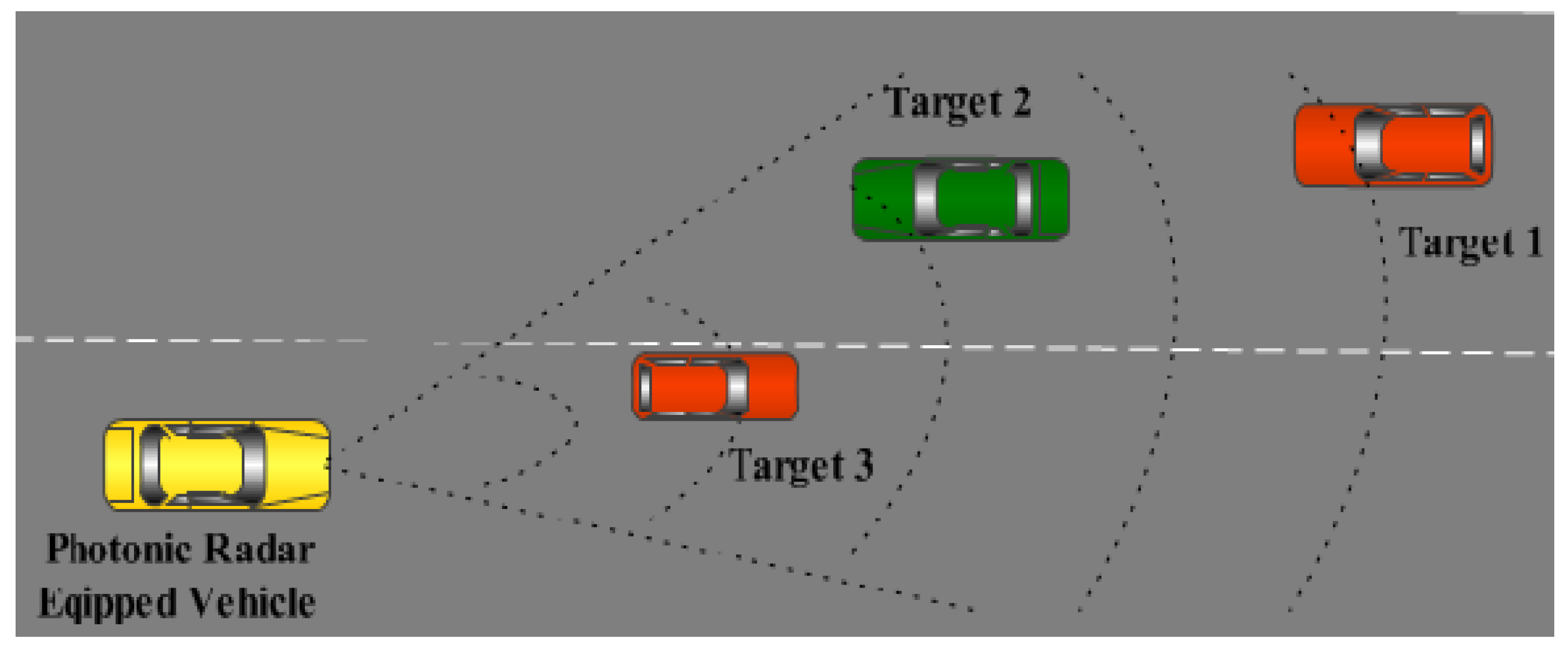
- Testing the system under adverse weather conditions using four targets in a complex recognition scenario;
- Evaluating the impact of different bandwidths in detection as well as on range resolution of multiple targets.
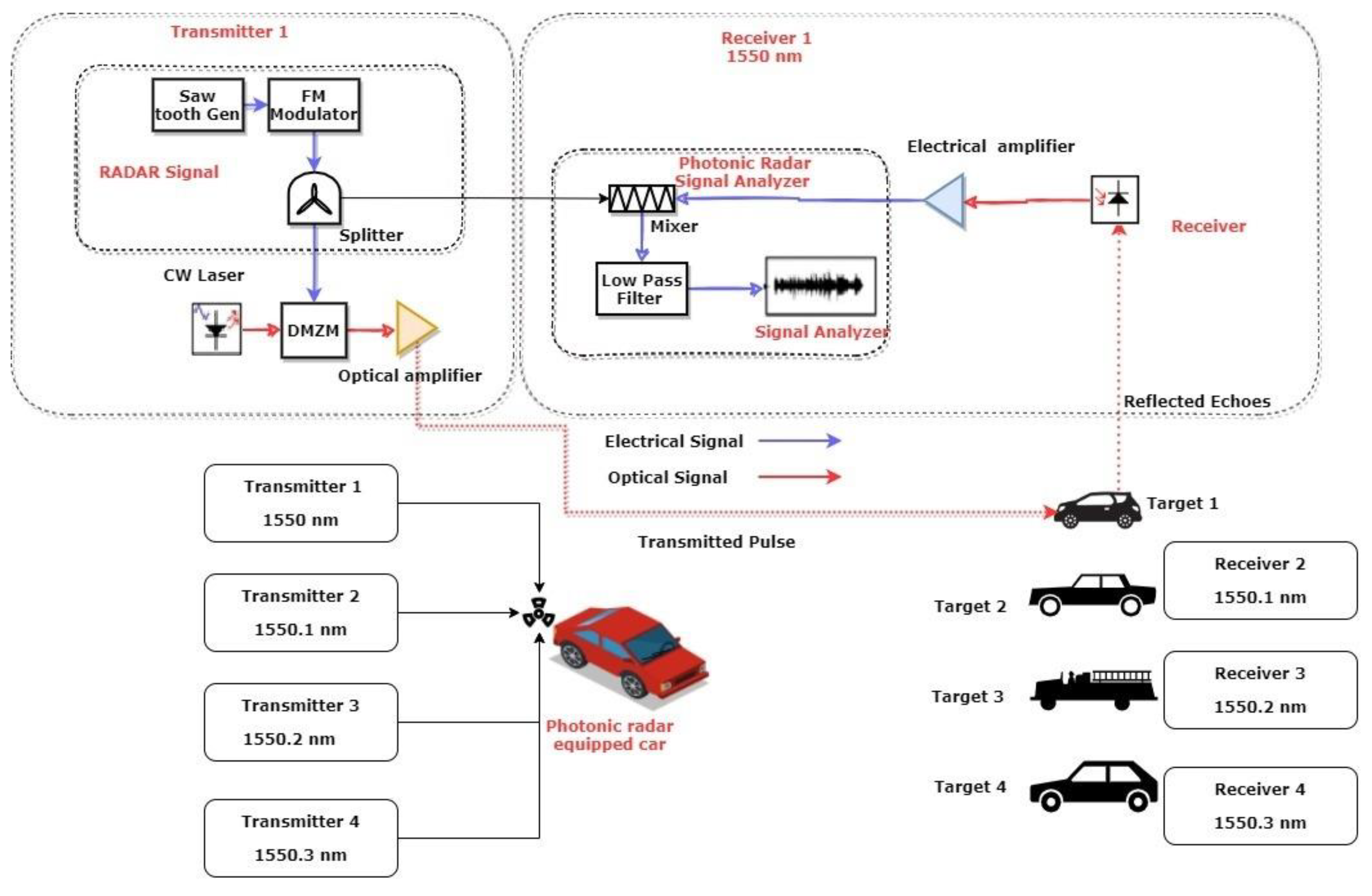
3. System Modeling and Working Principle
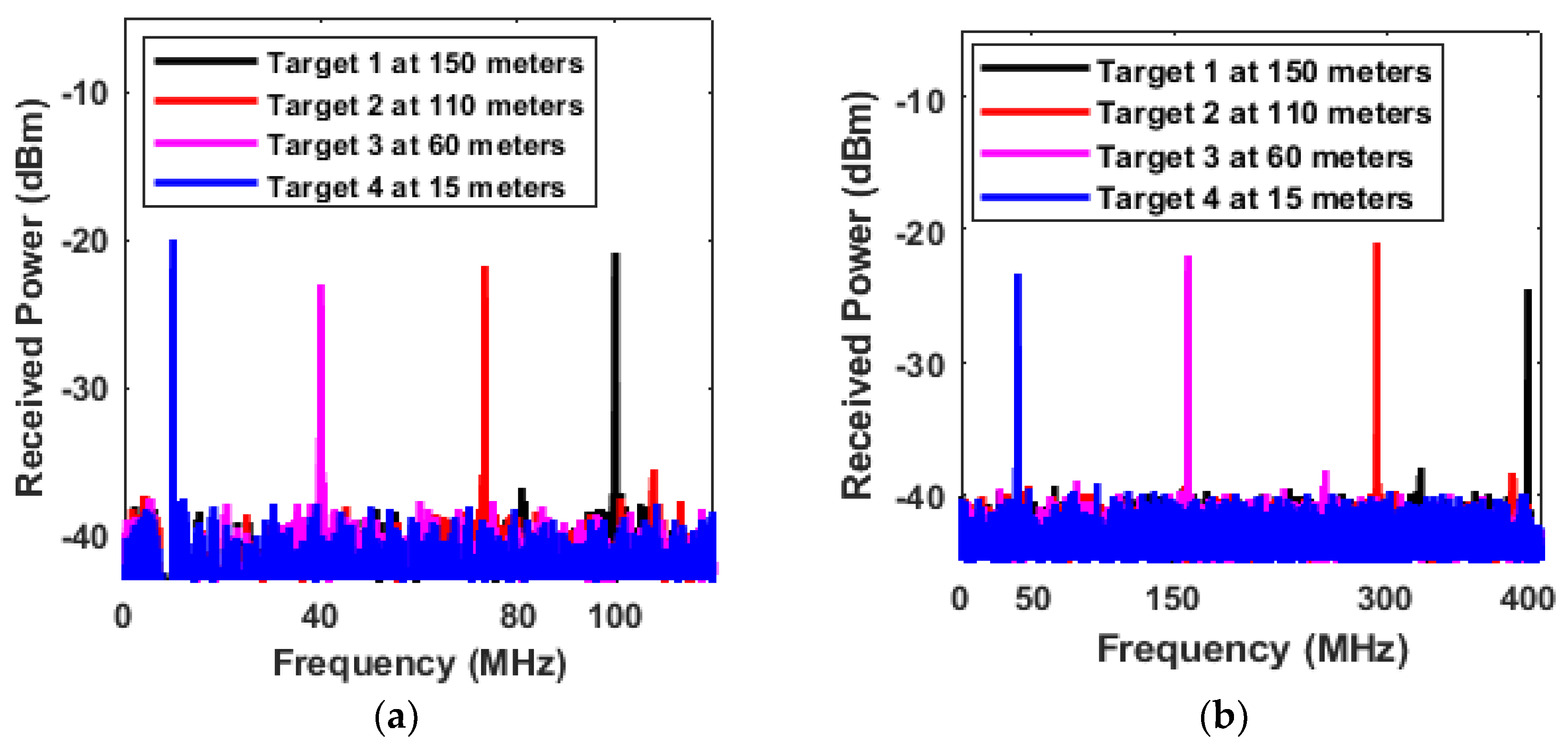
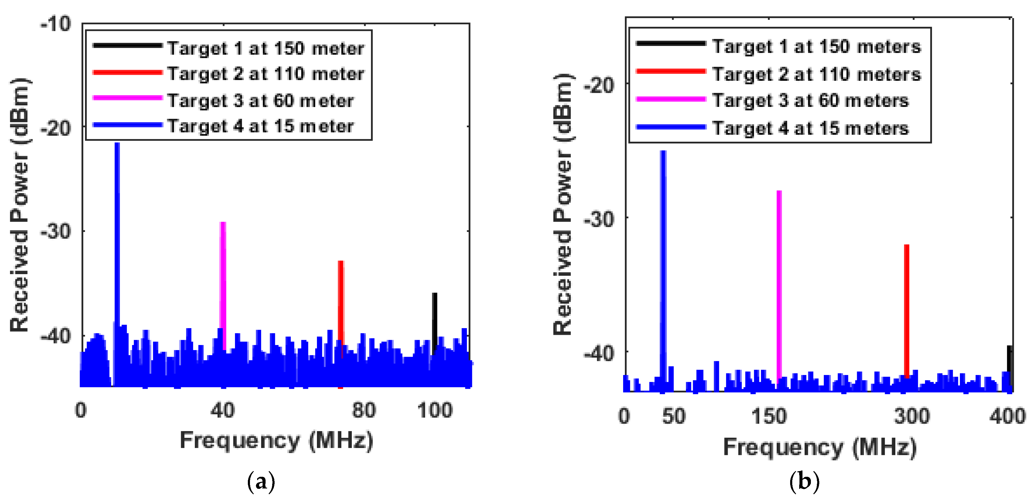
4. Results and Discussions
5. Conclusions
Author Contributions
Funding
Institutional Review Board Statement
Informed Consent Statement
Data Availability Statement
Acknowledgments
Conflicts of Interest
References
- World Health Organization. Road Traffic Injuries; World Health Organization: Geneva, Switzerland, 2021. [Google Scholar]
- U.S. Department Transportation. Automated Vehicles for Safety; U.S Department Transportation: Washington, DC, USA, 2017.
- Group, T. 7 Benefits of Autonomous Cars. 2017. Available online: https://www.thalesgroup.com/en/markets/digital-identity-and-security/iot/magazine/7-benefits-autonomous-cars (accessed on 30 August 2022).
- Lee, H.; Yoon, J.; Jeong, Y.; Yi, K. Moving Object Detection and Tracking Based on Interaction of Static Obstacle Map and Geometric Model-Free Approachfor Urban Autonomous Driving. IEEE Trans. Intell. Transp. Syst. 2021, 22, 3275–3284. [Google Scholar] [CrossRef]
- Skolnik, M.I. Introduction to Radar Systems; McGraw-Hill Education: New York, NY, USA, 1980. [Google Scholar]
- Giese, T.; Klappstein, J.; Dickmann, J.; Wöhler, C. Road course estimation using deep learning on radar data. In Proceedings of the 2017 18th International Radar Symposium (IRS), Prague, Czech Republic, 28–30 June 2017; pp. 1–7. [Google Scholar]
- Magnier, V.; Gruyer, D.; Godelle, J. Automotive LIDAR objects detection and classification algorithm using the belief theory. In Proceedings of the 2017 IEEE Intelligent Vehicles Symposium (IV), Los Angeles, CA, USA, 11–14 June 2017; pp. 746–751. [Google Scholar]
- Cui, S.L.Z.; Ye, X.; Feng, J.; Yang, Y.; He, Z.; Cong, R.; Zhu, D.; Zhang, F.; Pan, S. Chip-based photonic radar for high-resolution imaging. arXiv Preprint 2019, arXiv:1905.12802. [Google Scholar]
- Li, S.; Cui, Z.; Ye, X.; Feng, J.; Yang, Y.; He, Z.; Cong, R.; Zhu, D.; Zhang, F.; Pan, S. Chip-Based Microwave-Photonic Radar for High-Resolution Imaging. Laser Photonics Rev. 2020, 14, 1900239. [Google Scholar] [CrossRef]
- Bae, Y.; Shin, J.; Lee, S.G.; Kim, H. Field Experiment of Photonic Radar for Low-RCS Target Detection and High-Resolution Image Acquisition. IEEE Access 2021, 9, 63559–63566. [Google Scholar] [CrossRef]
- Premebida, C.; Monteiro, G.; Nunes, U.; Peixoto, P. A lidar and vision-based approach for pedestrian and vehicle detection and tracking. In Proceedings of the 2007 IEEE Intelligent Transportation Systems Conference, Bellevue, WA, USA, 30 September–3 October 2007; pp. 1044–1049. [Google Scholar]
- Sivaraman, S.; Trivedi, M.M. Looking at vehicles on the road: A survey of vision-based vehicle detection, tracking, and behavior analysis. IEEE Trans. Intell. Transp. Syst. 2013, 14, 1773–1795. [Google Scholar] [CrossRef]
- Roriz, R.; Cabral, J.; Gomes, T. Automotive LiDAR Technology: A Survey. IEEE Trans. Intell. Transp. Syst. 2022, 23, 6282–6297. [Google Scholar] [CrossRef]
- Shi, J.-W.; Guo, J.-I.; Kagami, M.; Suni, P.; Ziemann, O. Photonic technologies for autonomous cars: Feature introduction. Opt. Express 2019, 27, 7627–7628. [Google Scholar] [CrossRef]
- Dudek, M.; Nasr, I.; Bozsik, G.; Hamouda, M.; Kissinger, D.; Fischer, G. System analysis of a phased-array radar applying adaptive beam-control for future automotive safety applications. IEEE Trans. Veh. Technol. 2014, 64, 34–47. [Google Scholar] [CrossRef]
- Sharma, A.; Chaudhary, S.; Malhotra, J.; Parnianifard, A.; Wuttisittikulkij, L. Measurement of Target range and Doppler shift by incorporating PDM-enabled FMCW-based photonic radar. Optik 2022, 262, 169191. [Google Scholar] [CrossRef]
- SHARMA, A.; Chaudhary, S.; Malhotra, J.; Saadi, M.; Otaibi, S.A.; Nebhen, J.; Wuttisittikulkij, L. A Cost-Effective Photonic Radar under Adverse Weather conditions for Autonomous Vehicles by incorporating Frequency Modulated Direct Detection Scheme. Front. Phys. 2021, 467. [Google Scholar] [CrossRef]
- Chaudhary, S.; Wuttisittikulkij, L.; Saadi, M.; Sharma, A.; Al Otaibi, S.; Nebhen, J.; Rodriguez, D.Z.; Kumar, S.; Sharma, V.; Phanomchoeng, G. Coherent detection-based photonic radar for autonomous vehicles under diverse weather conditions. PLoS ONE 2021, 16, e0259438. [Google Scholar] [CrossRef] [PubMed]
- Karlsson, C.J.; Olsson, F.Å. Linearization of the frequency sweep of a frequency-modulated continuous-wave semiconductor laser radar and the resulting ranging performance. Appl. Opt. 1999, 38, 3376–3386. [Google Scholar] [CrossRef]
- Ghassemlooy, Z.; Popoola, W.; Rajbhandari, S. Optical Wireless Communications: System and Channel Modelling With MATLAB®; CRC Press: Boca Raton, FL, USA, 2019. [Google Scholar]
- Zhang, F.; Guo, Q.; Pan, S. Photonics-based real-time ultra-high-range-resolution radar with broadband signal generation and processing. Sci. Rep. 2017, 7, 13848. [Google Scholar] [CrossRef] [PubMed]
- Elghandour, A.H.; Ren, C.D. Modeling and comparative study of various detection techniques for FMCW LIDAR using optisystem. In Proceedings of the International Symposium on Photoelectronic Detection and Imaging 2013: Laser Sensing and Imaging and Applications, Beijing, China, 19 September 2013; p. 890529. [Google Scholar]
- Sharma, A.; Malhotra, J. Simulative investigation of FMCW based optical photonic radar and its different configurations. Opt. Quantum Electron. 2022, 54, 233. [Google Scholar] [CrossRef]
- Harris, M.; Young, R.I.; Köpp, F.; Dolfi, A.; Cariou, J.-P. Wake vortex detection and monitoring. Aerosp. Sci. Technol. 2002, 6, 325–331. [Google Scholar] [CrossRef]
- Dolfi-Bouteyre, A.; Canat, G.; Valla, M.; Augere, B.; Besson, C.; Goular, D.; Lombard, L.; Cariou, J.-P.; Durecu, A.; Fleury, D. Pulsed 1.5-$\mu $ m LIDAR for Axial Aircraft Wake Vortex Detection Based on High-Brightness Large-Core Fiber Amplifier. IEEE J. Sel. Top. Quantum Electron. 2009, 15, 441–450. [Google Scholar] [CrossRef]
- Kutila, M.; Pyykönen, P.; Ritter, W.; Sawade, O.; Schäufele, B. Automotive LIDAR sensor development scenarios for harsh weather conditions. In Proceedings of the 2016 IEEE 19th International Conference on Intelligent Transportation Systems (ITSC), Rio de Janeiro, Brazil, 1–4 November 2016; pp. 265–270. [Google Scholar]
- Series, P. Attenuation by Atmospheric Gases; Springer: Dordrecht, The Netherlands, 2016. [Google Scholar]
- Peynot, T.; Underwood, J.; Scheding, S. Towards reliable perception for unmanned ground vehicles in challenging conditions. In Proceedings of the 2009 IEEE/RSJ International Conference on Intelligent Robots and Systems, St. Louis, MO, USA, 10–15 October 2009; pp. 1170–1176. [Google Scholar]
- Wojtanowski, J.; Zygmunt, M.; Kaszczuk, M.; Mierczyk, Z.; Muzal, M. Comparison of 905 nm and 1550 nm semiconductor laser rangefinders’ performance deterioration due to adverse environmental conditions. Opto-Electron. Rev. 2014, 22, 183–190. [Google Scholar] [CrossRef]
- Bijelic, M.; Gruber, T.; Ritter, W. A benchmark for lidar sensors in fog: Is detection breaking down? In Proceedings of the 2018 IEEE Intelligent Vehicles Symposium (IV), Changshu, China, 26–30 June 2018; pp. 760–767. [Google Scholar]
- Rasshofer, R.H.; Spies, M.; Spies, H. Influences of weather phenomena on automotive laser radar systems. Adv. Radio Sci. 2011, 9, 49–60. [Google Scholar] [CrossRef]
- Hasirlioglu, S.; Riener, A.; Huber, W.; Wintersberger, P. Effects of exhaust gases on laser scanner data quality at low ambient temperatures. In Proceedings of the 2017 IEEE Intelligent Vehicles Symposium (IV), Los Angeles, CA, USA, 11–14 June 2017; pp. 1708–1713. [Google Scholar]
- Ramasubramanian, K.; Ramaiah, K. Moving from Legacy 24 GHz to State-of-the-Art 77-GHz Radar. ATZelektronik Worldw. 2018, 13, 46–49. [Google Scholar] [CrossRef]
- Meena, D.; Francis, F.; Sarath, K.; Dipin, E.; Srinivas, T. Feasibility analysis of WDM links for radar applications. Def. Technol. 2015, 11, 76–84. [Google Scholar] [CrossRef]
- Liu, X.; Wang, K. Research on high-resolution wide-swath SAR based on microwave photonics. In Proceedings of the 2016 CIE International Conference on Radar (RADAR), Guangzhou, China, 10–13 October 2016; pp. 1–3. [Google Scholar]
- Li, R.; Li, W.; Ding, M.; Wen, Z.; Li, Y.; Zhou, L.; Yu, S.; Xing, T.; Gao, B.; Luan, Y. Demonstration of a microwave photonic synthetic aperture radar based on photonic-assisted signal generation and stretch processing. Opt. Express 2017, 25, 14334–14340. [Google Scholar] [CrossRef]
- Meng, Z.; Li, J.; Yin, C.; Fan, Y.; Yin, F.; Zhou, Y.; Dai, Y.; Xu, K. Dual-band dechirping LFMCW radar receiver with high image rejection using microwave photonic I/Q mixer. Opt. Express 2017, 25, 22055–22065. [Google Scholar] [CrossRef] [PubMed]
- Shibagaki, N. Experimental study of photonic based radar for FOD detection systems using 90 GHz-band. In Air Traffic Management and Systems II; Springer: Berlin, Germany, 2017; pp. 239–248. [Google Scholar]
- Qian, N.; Zou, W.; Zhang, S.; Chen, J. Signal-to-noise ratio improvement of photonic time-stretch coherent radar enabling high-sensitivity ultrabroad W-band operation. Opt. Lett. 2018, 43, 5869–5872. [Google Scholar] [CrossRef]
- Sharma, V.; Sergeyev, S. Range detection assessment of photonic radar under adverse weather perceptions. Opt. Commun. 2020, 472, 125891. [Google Scholar] [CrossRef]
- Shakthi Murugan, K.H.; Sharma, A.; Malhotra, J. Performance analysis of 80 Gbps Ro-FSO system by incorporating hybrid WDM-MDM scheme. Opt. Quantum Electron. 2020, 52, 505. [Google Scholar] [CrossRef]
- Chaudhary, S.; Chauhan, P.; Sharma, A. High Speed 4× 2.5 Gbps-5 GHz AMI-WDM-RoF Transmission System for WLANs. J. Opt. Commun. 2019, 40, 285–288. [Google Scholar] [CrossRef]
- Zhou, Z.; Zhang, H.; Lin, C.; Sharma, A. Performance analysis of duobinary and CSRZ modulation based polarization interleaving for high-speed WDM-FSO transmission system. J. Opt. Commun. 2022, 43, 147–152. [Google Scholar] [CrossRef]
- Chaudhary, S.; Sharma, A.; Chaudhary, N. 6 × 20 Gbps Hybrid WDM–PI Inter-satellite System under the Influence of Transmitting Pointing Errors. J. Opt. Commun. 2016, 37, 375–379. [Google Scholar] [CrossRef]
- Chen, Y.; Weng, B.; Liu, J. A novel photonic-based MIMO radar architecture with all channels sharing a single transceiver. IEEE Access 2019, 7, 165093–165102. [Google Scholar] [CrossRef]
- Dong, J.; Zhang, F.; Jiao, Z.; Sun, Q.; Li, W. Microwave photonic radar with a fiber-distributed antenna array for three-dimensional imaging. Opt. Express 2020, 28, 19113–19125. [Google Scholar] [CrossRef] [PubMed]
- Yao, X.S.; Liu, X.; Hao, P. Scan-less 3D optical sensing/Lidar scheme enabled by wavelength division demultiplexing and position-to-angle conversion of a lens. Opt. Express 2020, 28, 35884–35897. [Google Scholar] [CrossRef] [PubMed]
- Zhou, P.; Zhang, F.; Pan, S. Generation of linear frequency-modulated waveforms by a frequency-sweeping optoelectronic oscillator. J. Lightwave Technol. 2018, 36, 3927–3934. [Google Scholar] [CrossRef]
- Coutinho, O.L.; Almeida, V.R.; Oliveira, J.E.B. Analysis of analog fiber optical links based on DSB+ C and SSB+ C modulation techniques. In Proceedings of the SBMO/IEEE MTT-S International Conference on Microwave and Optoelectronics, 2005, Brasilia, Brazil, 25 July 2005; pp. 439–443. [Google Scholar]
- Hui, R.; O’Sullivan, M. Fiber Optic Measurement Techniques; Academic Press: San Diego, CA, USA, 2009. [Google Scholar]
- Agrawal, G.P. Fiber-Optic Communication Systems; John Wiley & Sons: New York, NY, USA, 2012; Volume 222. [Google Scholar]
- Keiser, G. Optical Communications Essentials; McGraw-Hill Education: Berkshire, UK, 2003. [Google Scholar]
- Ricchiuti, A.L.; Hervás, J.; Barrera, D.; Sales, S.; Capmany, J. Microwave photonics filtering technique for interrogating a very-weak fiber Bragg grating cascade sensor. IEEE Photonics J. 2014, 6, 1–10. [Google Scholar] [CrossRef]
- Marques, C.A.; Leal-Junior, A.G.; Min, R.; Domingues, M.; Leitão, C.; Antunes, P.; Ortega, B.; André, P. Advances on polymer optical fiber gratings using a KrF pulsed laser system operating at 248 nm. Fibers 2018, 6, 13. [Google Scholar] [CrossRef]
- Cheng, B.; Song, Y.; Hua, L.; Xiao, H. Fabrication and characterization of femtosecond laser induced microwave frequency photonic fiber grating. J. Lightwave Technol. 2020, 38, 5286–5292. [Google Scholar] [CrossRef] [PubMed]
- Liang, H.; Ying, K.; Wang, D.; Pi, H.; Li, X.; Wang, Z.; Wei, F.; Cai, H. All-fiber narrow-bandwidth rectangular Optical filter with reconfigurable bandwidth and tunable center wavelength. Opt. Express 2021, 29, 11739–11749. [Google Scholar] [CrossRef]
- Miclea, R.-C.; Dughir, C.; Alexa, F.; Sandru, F.; Silea, I. Laser and LIDAR in A system for visibility distance estimation in fog conditions. Sensors 2020, 20, 6322. [Google Scholar] [CrossRef]
- Al Naboulsi, M.C.; Sizun, H.; de Fornel, F. Fog attenuation prediction for optical and infrared waves. Opt. Eng. 2004, 43, 319–329. [Google Scholar] [CrossRef]
- Rashidi, F.; He, J.; Chen, L. Spectrum slicing WDM for FSO communication systems under the heavy rain weather. Opt. Commun. 2017, 387, 296–302. [Google Scholar] [CrossRef]
- Olsen, R.; Rogers, D.; Hodge, D. The aRbrelation in the calculation of rain attenuation. IEEE Trans. Antennas Propag. 1978, 26, 318–329. [Google Scholar] [CrossRef]
- Awan, M.S.; Marzuki; Leitgeb, E.; Hillbrand, B.; Nadeem, F.; Khan, M.S. Cloud attenuations for free-space optical links. In Proceedings of the 2009 International Workshop on Satellite and Space Communications, Siena, Italy, 9–11 September 2009; pp. 274–278. [Google Scholar]
- Serafino, G.; Amato, F.; Maresca, S.; Lembo, L.; Ghelfi, P.; Bogoni, A. Photonic approach for on-board and ground radars in automotive applications. IET Radar Sonar Navig. 2018, 12, 1179–1186. [Google Scholar] [CrossRef]
- Wang, Y.; Hou, X.; Li, T.; He, Z.; Wang, D.; Yang, F.; Zhou, T.; Rong, L. Simultaneous detection of the distance and direction for a noncooperative target based on the microwave photonic radar. Opt. Express 2021, 29, 31561–31573. [Google Scholar] [CrossRef] [PubMed]
- Liang, D.; Jiang, L.; Chen, Y. Multi-Functional Microwave Photonic Radar System for Simultaneous Distance and Velocity Measurement and High-Resolution Microwave Imaging. J. Lightwave Technol. 2021, 39, 6470–6478. [Google Scholar] [CrossRef]
- Ding, Y.; Guo, S.; Wu, H.; Wang, D.; Li, J.; Yang, Y.; Cui, F.; Dong, W. Dual-Chirp Photonics-Based Radar for Distance and Velocity Measurement Based on Compressive Sensing. IEEE Photonics J. 2022, 14, 5541807. [Google Scholar] [CrossRef]
- Bai, W.; Li, P.; Zou, X.; Zhou, Z.; Pan, W.; Yan, L.; Luo, B.; Fang, X.; Jiang, L.; Chen, L. Millimeter-wave joint radar and communication system based on photonic frequency-multiplying constant envelope LFM-OFDM. Opt. Express 2022, 30, 26407–26425. [Google Scholar] [CrossRef]


| Component | Parameter | Value |
|---|---|---|
| Continuous Wave laser | Wavelength Channel Spacing Linewidth Power | 1550–1550.3 nm 0.1 nm 100 KHz 100 µW |
| Dual Port Mech-Zhender modulator (DP-MZM) | Extinction ratio Switching bias voltage Switching RF voltage Bias voltage | 30 dB 4 V 4 V 0 V |
| Simulation window | Sweep time No. of samples | 10 µs 8192 |
| Photo detector (PIN) | Responsivity Dark current Thermal and shot noise BW Absolute temp Load resistance | 1 A/W 1 nA 410 MHz 290 k 50 Ω |
| Attenuation Level | Power (dBm) | SNR (dB) | ||||||
|---|---|---|---|---|---|---|---|---|
| Ch 1 at 150 m | Ch 2 at 110 m | Ch 3 at 60 m | Ch 4 at 15 m | Ch 1 at 150 m | Ch 2 at 110 m | Ch 3 at 60 m | Ch 4 at 15 m | |
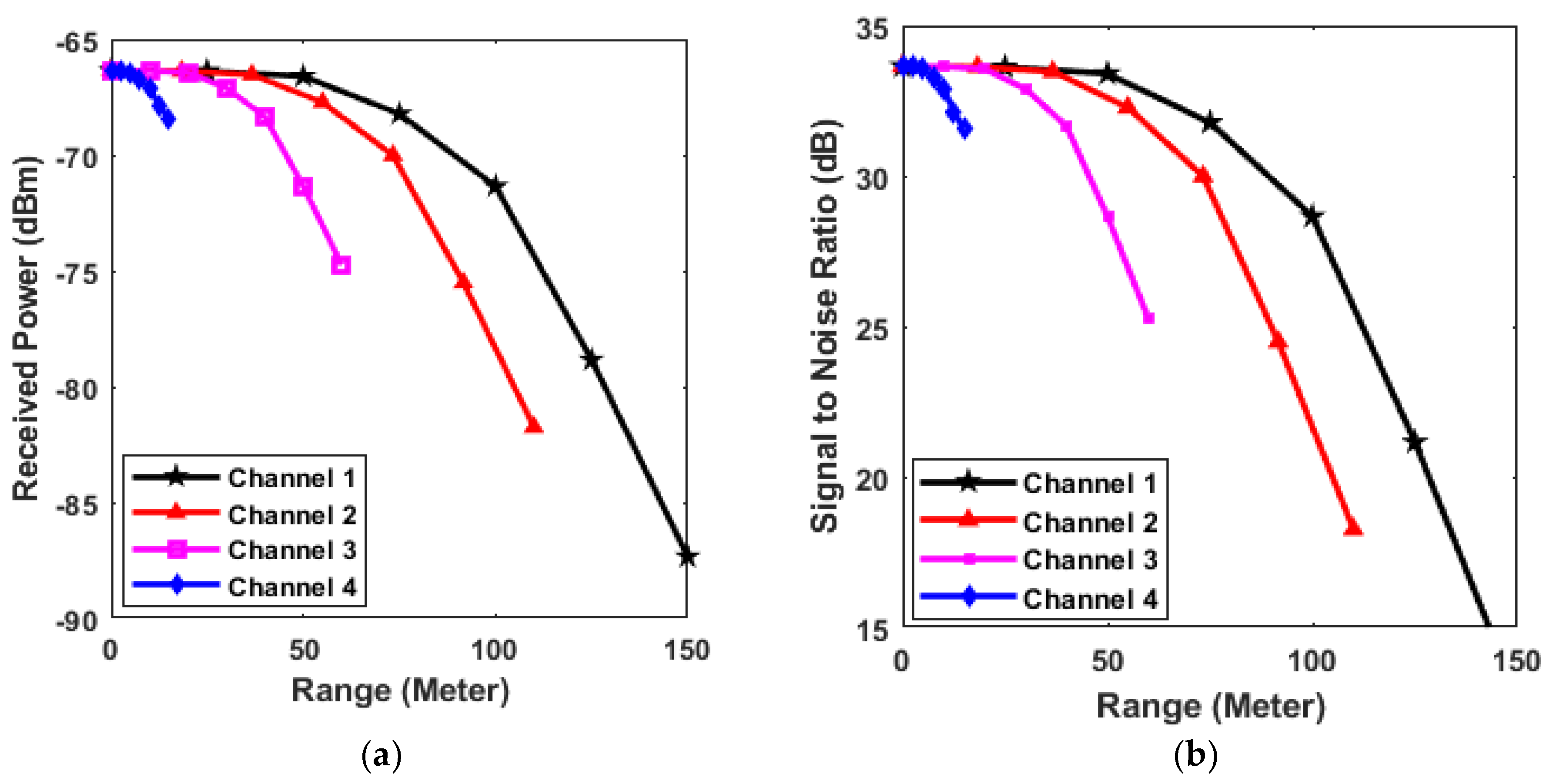
| Thick Fog (70 dB/km) | −87.34 | −81.74 | −74.74 | −68.44 | 12.65 | 18.25 | 25.25 | 31.55 |
| Heavy Fog (50 dB/km) | −81.34 | −77.34 | −72.34 | −67.84 | 18.65 | 22.65 | 27.65 | 32.15 |
| Moderate Fog (25 dB/km) | −73.84 | −71.84 | −69.34 | −67.09 | 26.15 | 28.15 | 30.65 | 32.90 |
| Strong Rain and Low Fog (12.5 dB/km) | −70.04 | −69.09 | −67.84 | −66.72 | 29.90 | 30.90 | 32.15 | 33.27 |
| Light Rain (2.5 dB/km) | −67.64 | −66.89 | −66.64 | −66.42 | 32.90 | 33.10 | 33.35 | 33.57 |
| Clear (0 dB/km) | −66.34 | −66.34 | −66.34 | −66.34 | 33.65 | 33.65 | 33.65 | 33.65 |
| Attenuation Level | Power (dBm) | SNR (dB) | ||||||
|---|---|---|---|---|---|---|---|---|
| Ch 1 at 150 m | Ch 2 at 110 m | Ch 3 at 60 m | Ch 4 at 15 m | Ch 1 at 150 m | Ch 2 at 110 m | Ch 3 at 60 m | Ch 4 at 15 m | |
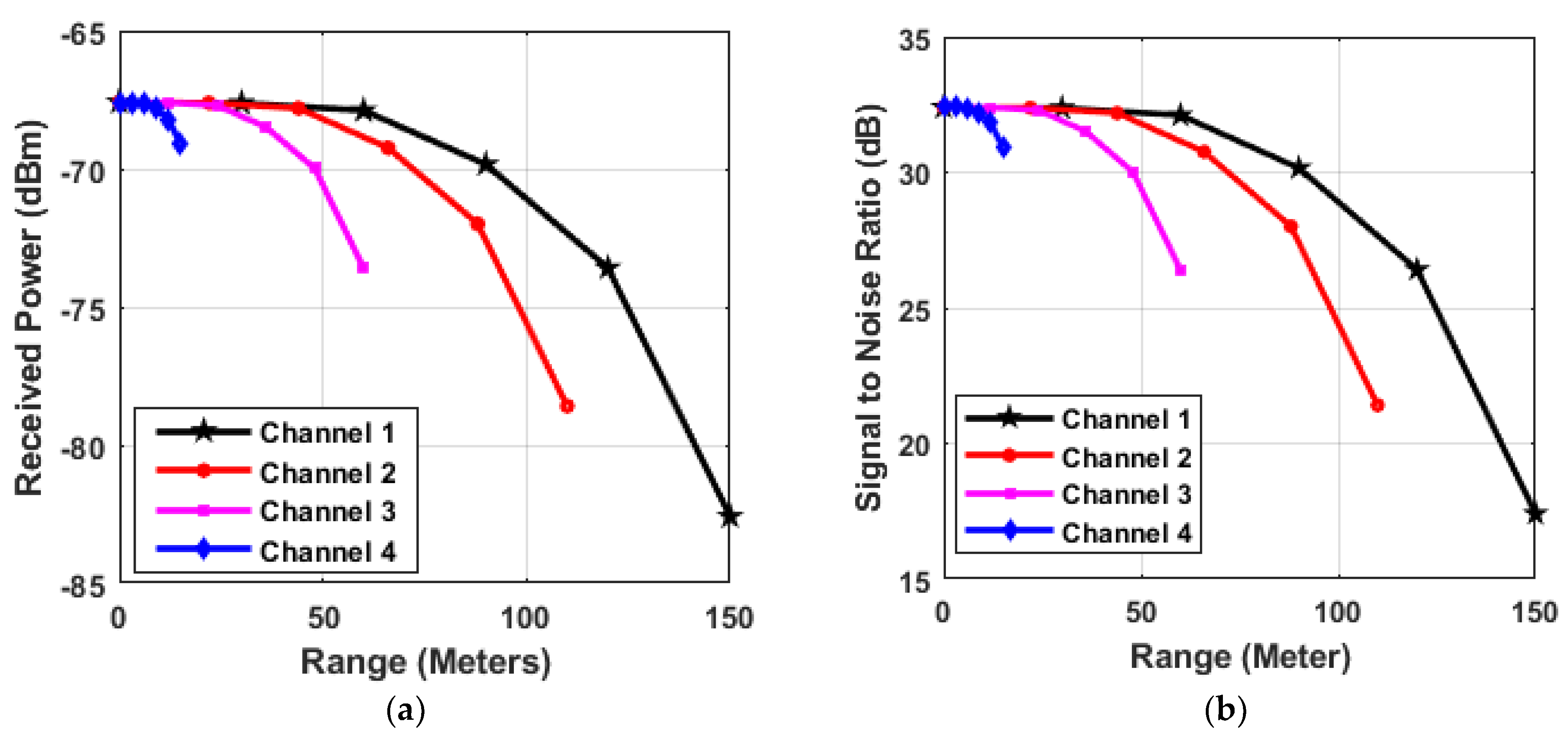
| Thick Fog (70 dB/km) | −82.58 | −78.59 | −73 | −69.50 | 17.40 | 21.40 | 26.40 | 30.90 |
| Heavy Fog (50 dB/km) | −75.89 | −73.09 | −70.59 | −68.34 | 24.90 | 26.70 | 29.40 | 31.65 |
| Moderate Fog (25 dB/km) | −71.34 | −70.39 | −69.09 | −67.96 | 28.65 | 29.67 | 30.90 | 32.03 |
| Strong Rain and Low Fog (12.5 dB/km) | −68.34 | −68.14 | −67.89 | −67.66 | 31.65 | 31.85 | 32.10 | 32.33 |
| Light Rain (2.5 dB/km) | −67.59 | −67.59 | −67.59 | −67.59 | 32.40 | 32.40 | 32.40 | 32.40 |
| Clear (0 dB/km) | −82.58 | −78.59 | −73 | −69.50 | 17.40 | 21.40 | 26.40 | 30.90 |
| Ref. | No. of Targets | Range | Operational Bandwidth | Range Resolution | Turbulences |
|---|---|---|---|---|---|
| [62] | 1 | 15 m | 24 and 77 GHz | Not Reported | Not Reported |
| [63] | 1 | 11 m | 40 GHz | Not Reported | Not Reported |
| [64] | 1 | 1.72 m | 8.5 to 12.5 GHz | 5.9 cm | Not Reported |
| [65] | 1 | 51 m | 10 GHz | Not reported | Not reported |
| [66] | 2 | 2 m | 10 GHz | 1.5 cm | Not reported |
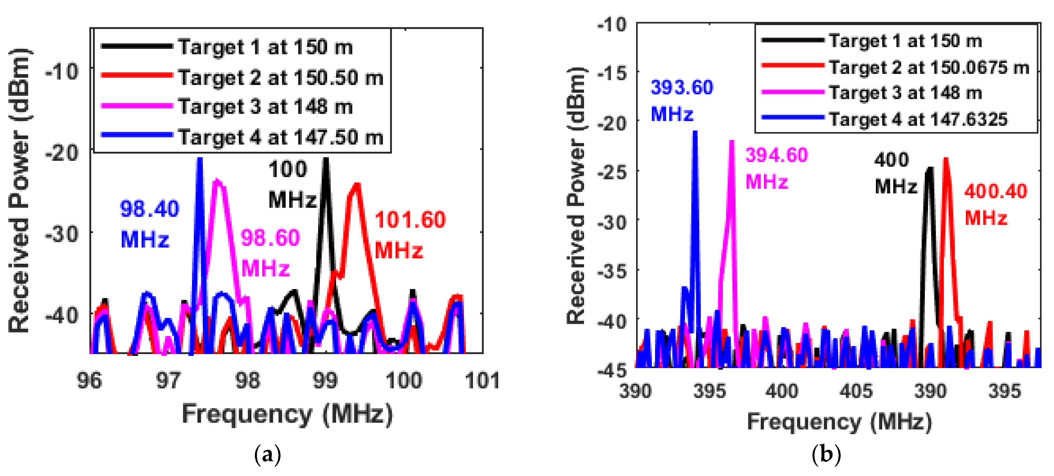
| Our work | 4 | 150 m | 77 GHz | 6.75 cm | Heavy Fog (70 dB/Km) |
Publisher’s Note: MDPI stays neutral with regard to jurisdictional claims in published maps and institutional affiliations. |
© 2022 by the authors. Licensee MDPI, Basel, Switzerland. This article is an open access article distributed under the terms and conditions of the Creative Commons Attribution (CC BY) license (https://creativecommons.org/licenses/by/4.0/).
Share and Cite
Sharma, A.; Chaudhary, S.; Malhotra, J.; Khichar, S.; Wuttisittikulkij, L. Photonic Sensor for Multiple Targets Detection under Adverse Weather Conditions in Autonomous Vehicles. J. Sens. Actuator Netw. 2022, 11, 60. https://doi.org/10.3390/jsan11040060
Sharma A, Chaudhary S, Malhotra J, Khichar S, Wuttisittikulkij L. Photonic Sensor for Multiple Targets Detection under Adverse Weather Conditions in Autonomous Vehicles. Journal of Sensor and Actuator Networks. 2022; 11(4):60. https://doi.org/10.3390/jsan11040060
Chicago/Turabian StyleSharma, Abhishek, Sushank Chaudhary, Jyoteesh Malhotra, Sunita Khichar, and Lunchakorn Wuttisittikulkij. 2022. "Photonic Sensor for Multiple Targets Detection under Adverse Weather Conditions in Autonomous Vehicles" Journal of Sensor and Actuator Networks 11, no. 4: 60. https://doi.org/10.3390/jsan11040060