1. Introduction
Haptic devices are systems used to increase the user’s immersion for different applications, such as gaming [
1], medicine [
2,
3] and virtual reality [
4,
5]. Furthermore, they are used for tasks where visual information is not sufficient; for example, the manipulation of radioactive objects. Parallel architecture has been selected to develop many haptic devices due to their performances: high stiffness, load capability and low weight. Spherical parallel manipulators (SPMs), that have a fixed Center of Rotation (CoR), are a class of parallel mechanisms providing three degrees of freedom of pure rotation. Some haptic devices with a parallel spherical structure have been developed, such as the haptic device proposed by Birglen et al. [
6] to control the orientation of a camera [
7] and the haptic device proposed by Saafi et al. [
8] for medical teleoperation system to control a slave robot.
The kinematic performance of Parallel Manipulators (PMs), as well as its dynamic behaviour, depend on its dimensional synthesis. Many recent works focus on the design of PMs. Saafi et al. [
9] compared two optimally designed parallel manipulator: redundant 2-DoF PM and non-redundant one. This work showed that the non-redundant and optimally designed is a better choice for haptic uses. Ben Hamida et al. [
10] presented an approach based on a multi-objective optimization for dimensional parameter identification of four types of translational parallel manipulators (PMs). These PMs are Delta, 3-UPU, RAF, and Tri-pyramid Robots. The optimisation approach allows to identify suitable optimal solutions with compromises. Mores studies [
11,
12,
13] have focused on this issue and concluded that the equilibrium between criteria such as dexterity and workspace is difficult to reach.
The SPM, like many parallel robots, suffer from parallel singularities. This type of singularity may appear at the center of the workspace and generates large actuator torques and a loss of stiffness. In singular configurations, a parallel manipulator loses one or more of its degrees of freedom. Several works have tried to eliminate this type of singularity from the workspace of the parallel robot by optimizing its geometry [
14,
15], but by improving the kinematic behavior, the parallel robot structure becomes bigger and a problem of interference is generated [
7]. Other works addressed the singularity issues and the complexity of forward kinematic model of the SPM by proposing the use of redundancy.
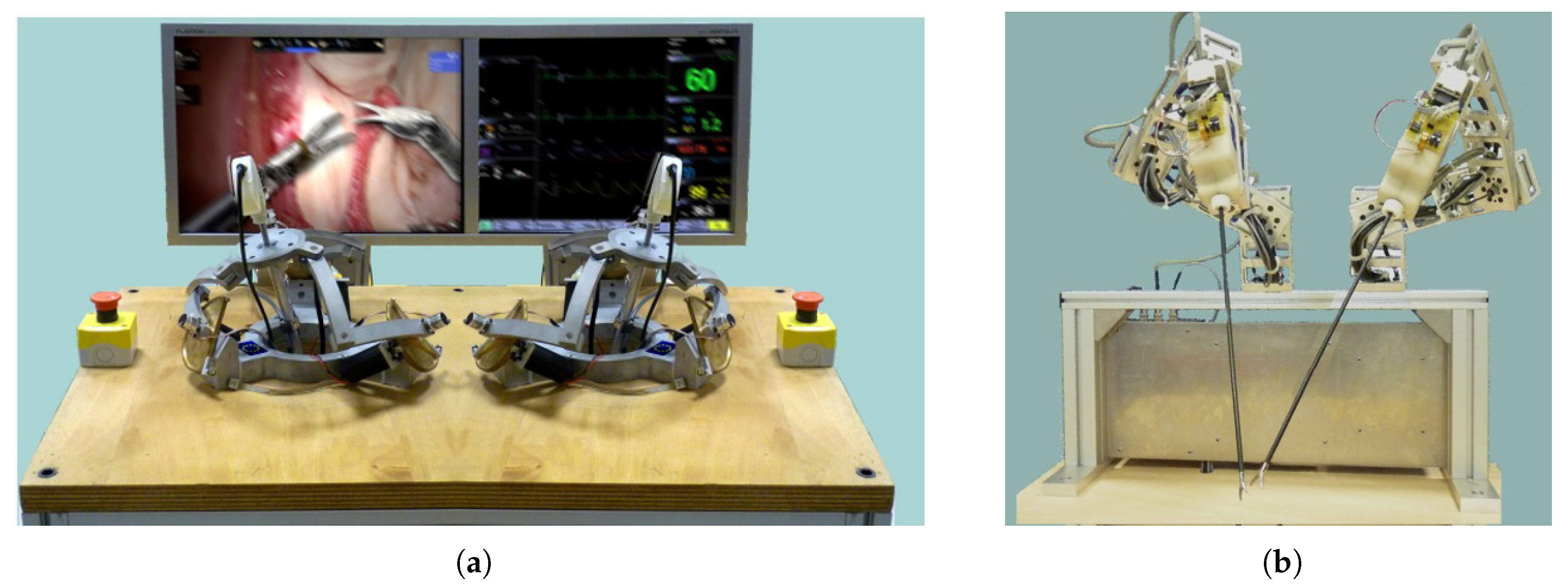
The first prototype of the haptic device has a classical spherical parallel architecture (
Figure 1a). The self-rotation was not considered in the optimization process and this induces the presence of the parallel singularities inside the workspace of the SPM. The parallel singularity has negative effects on the manipulator behavior. Thus, the kinematic transformation from the Joint space to the Cartesian space is disturbed by errors amplification. Further, the torques of the actuated joints are amplified. To cope with these problems several solutions based on redundancy have been proposed. The first solution is focused on the improvement of the accuracy of the FKM in singular region by using an additional sensor [
16]. This solution has allowed the simplification of the kinematic model and reducing the computing time. The second solution is focused on the use of a redundant actuator to avoid the exceed of torque limits [
17]. The two solutions have solved the issues of parallel singularities. However, the additional actuator increases the weight of the moving platform.
In this paper, a new prototype of the master device, with partial kinematic change, is studied (
Figure 1b). Only one leg of the classical Spherical Parallel Manipulator is modified by URU architecture (U for Universal joint and R for Revolute joint). Yet, the spherical motion is ensured by the two other legs with RRR architecture. The resolution of the forward kinematic model of this new master device as well as the real-time issue is developed in this paper. Three approaches are compared. The most suitable one is chosen and implemented to control the motion of the surgical slave robot. This approach is based on computing the FKM of a serial RRR leg of the special SPM. This method is implemented in the control system and is tested experimentally by an expert surgeon.
The paper is organized as follows:
Section 2 focuses on the presentation of the tele-operation system in the context of minimally invasive surgery. In
Section 3, the kinematic of the new spherical parallel manipulator is presented. The behavior improvement as well as the singularity free workspace are discussed.
Section 4 presents the three proposed methods to solve the forward kinematic model.
Section 5 presents the experimental comparison between the three proposed methods. Validations of the proposed real-time method and the tele-operation system are carried-out in
Section 6. Conclusions and perspectives are presented in
Section 7.
2. Tele-Operation System
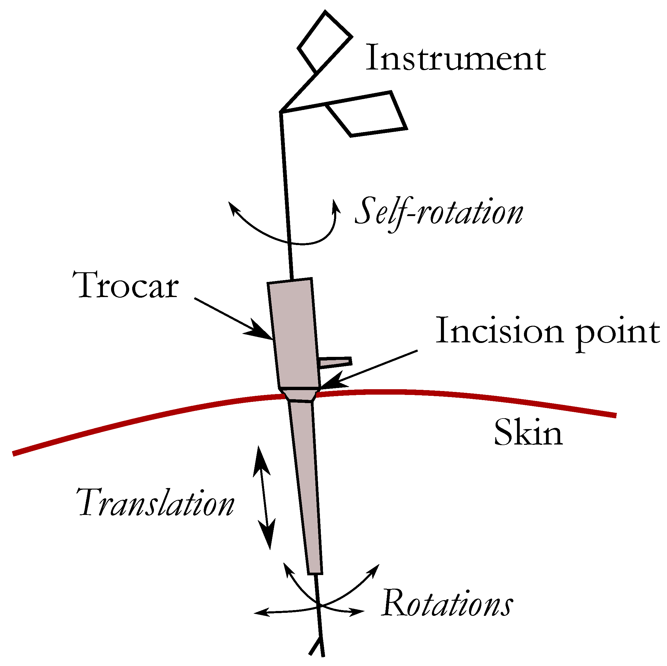
In the medical field, tele-operation systems are not designed to yield autonomous operation but to assist the expert by adding more security and accuracy to the medical operation. The proposed tele-operation system is dedicated for Minimally Invasive Surgery (MIS) performed through small incisions. The instruments in MIS are designed to enter into the patient body through tiny incision points by a trocar, see
Figure 2. In this kind of medical intervention, motions of the instruments are limited to three rotations around the incision point and one translation within the instrument axis.
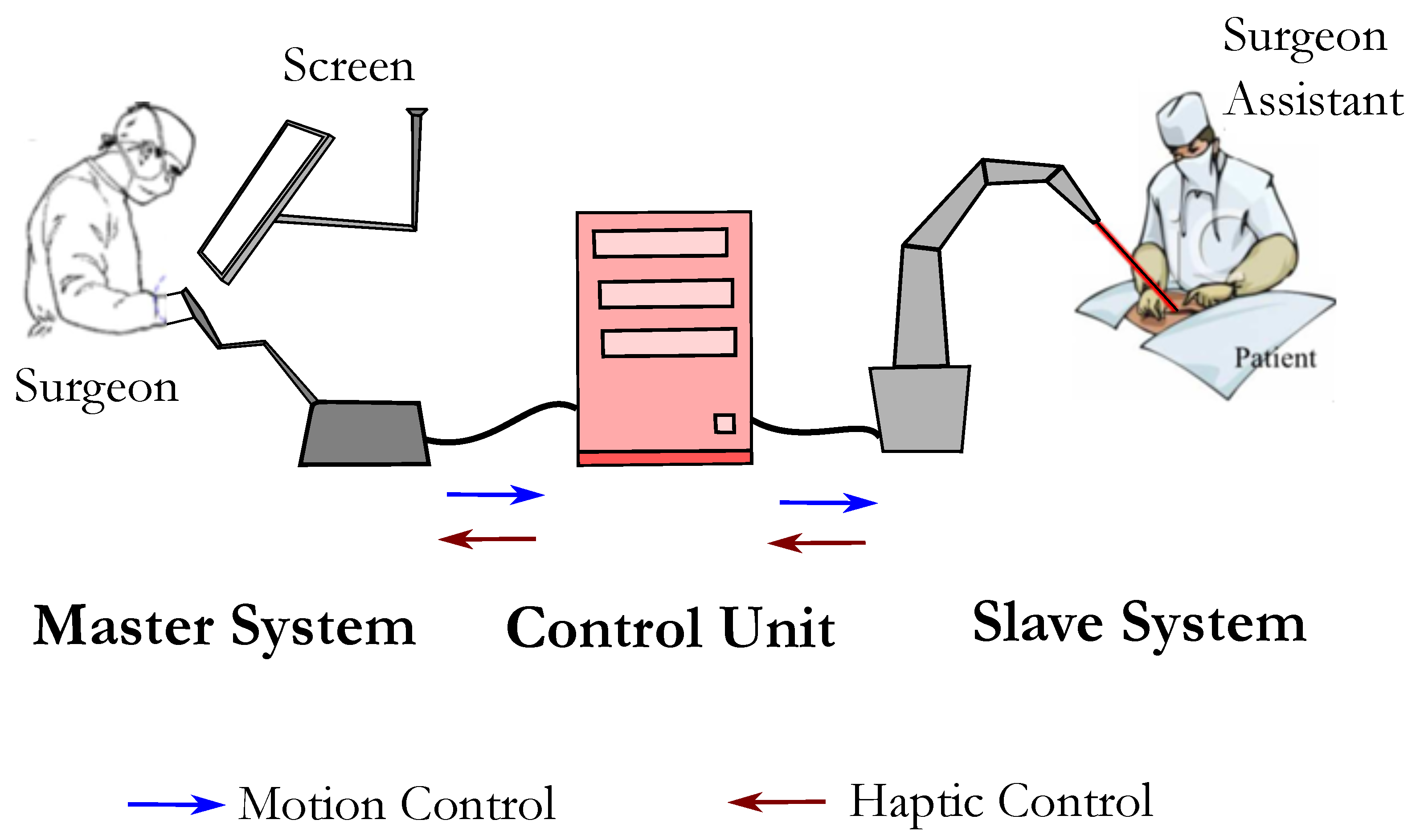
The surgeons are therefore called to learn a new form of hand-eye coordination and to become skillful in the manipulation of instruments. The use of these latter from the outside of the body made possible robotizing this technique. A robot, operating on a distant patient, is then controlled by an expert surgeon through a haptic interface. The latter device should be able to reproduce the expert movement with high transparency and provide a force rendering, that one calls a tele-operation system. A Tele-operation system synoptic is represented in
Figure 3. It’s important to highlight that nowadays no commercial system is providing haptic feedback and the force rendering is still focused in research purpose.
A PROMIS (Pprime RObot for Minimally Invasive Surgery) system is designed for collaborative operation between the surgeon and the robot. This system is composed of a master device and a slave device as is shown in
Figure 4. The surgical robot has a RRR spherical serial structure with a prismatic joint at the end. Its kinematic was optimized to get a compact structure. The tool is hold by an effector with two DoFs: self rotation and opening/closing. This paper focuses on the study of the master device. Its kinematic is studied in the next sections.
3. Kinematic of the Modified Spherical Parallel Manipulator
The kinematic model of the spherical parallel manipulator is as follow:
where,
is the angular velocity of the moving-platform,
is the angular velocity of active joint,
is the parallel part of the Jacobian matrix and
is the serial part of the Jacobian matrix. The two matrices
A and
B are
.
The Jacobian matrix of parallel manipulators is as follows:
Parallel singularity appears when the determinant of the matrix
vanishes. This appears when the three columns of the matrix
are linearly dependents. Each column of the matrix
corresponds to one leg of the parallel robot. In order to eliminate the parallel singularity from the workspace of the spherical parallel manipulator, the kinematic of one leg is changed. One leg with RRR architecture is replaced by a leg with URU architecture (R for Revolute joint and U for Universal Joint). Two legs are kept the same in order to maintain the spherical behavior of the device. The New SPM has three degrees of freedom of pure rotation described by the Euler angles
,
and
. The kinematic of the new manipulator is presented in
Figure 5.
Figure 6 shows the kinematic of the two legs. The RRR leg (
Figure 6a) has two links: the first one is defined by the angle
and the second link is defined by the angle
. Moreover, the angle
is the angle between
(
) and
(the center of the end-effector). Birglen et al. [
6] proposed a similar architecture to eliminate interference between legs for the haptic device.
The kinematic model of the haptic device can be written as follows. For the leg B and C, we can write:
This equation can be obtained since the scalar product of two vectors is the cosine of the angle between them. And, as illustrated in
Figure 6a, the angle between
and
is
.
By differentiating the Equation (
3), we get:
with,
with,
is the angular velocity of the moving platform. The kinematic model of leg B and C is as follows:
For the leg A with the new architecture, we have:
To get a relation between
and the active angle
, Equation (
7) is multiplied by the vector
orthogonal to
,
,
and
. We obtain:
with,
The matrices
A and
B are as follows:
The dexterity can be used to evaluate the presence of the singularity in the workspace of the parallel robot. The dexterity is expressed as follows:
where
is the condition number of the Jacobian matrix. It has the following expression:
The dexterity distributions for
,
and
are presented in the
Figure 7. The distribution shows that there are no singularities in the workspace of the New SPM and especially at its center. After this stage, a real master device has been developed (
Figure 1b). The prototype was equipped with sensors and actuators. This prototype is designed to control the motion of the surgical robot. For this, we need to solve the Forward Kinematic model of the new SPM in Real-Time. In the next section, we discuss the resolution of the Forward Kinematic Model.
4. Methods to Solve the FKM
Three methods have been detailed in this paper to solve the direct model of the proposed SPM. Three sensors fixed on the base are used in the first method, called classic FKM. Four sensors, three on the base and one on a passive joint of the moving platform, are used in the second method and called improved FKM. The third method uses three sensors on one leg and installed in serial configuration, called serial FKM.
4.1. Classical Method to Solve the Forward Kinematic Model
The FKM expresses the orientation of the moving platform described by the Euler angle (
,
,
), using the active joint angles (
,
,
). Bai et al. [
18] proposed a method based on the input/output equations of spherical four-bar mechanisms to solve the FKM of the classical SPM. This approach is adapted to the modified SPM. Only one loop describing the spherical four-bar mechanism is given. This closed loop is passing by the second link of the legs B, the moving platform (between
and
axes), the second link of the legs C and finally, a fictive link between the joints with axis
and the axis
(see
Figure 8). As for the planar four-bar mechanisms, the spherical one has a geometrical equation relating two angles called input/output angles. This two angles are
and
(
Figure 8).
The input/output equation of the spherical four-bar mechanism is defined as:
where
,
and
are functions of
and
.
This equation is detailed in [
16,
18]. A second equation is needed to solve the FKM of this SPM. This equation is given by the scalar product of vectors
and
as follows:
with,
is orthogonal to
because
is in the plan formed by
and
(see
Figure 6b).
After arrangement, we get the following expression:
where
,
and
are functions of
and
. The expressions of
and
are computed using Equations (
14) and (
17) as follows:
The equation with
as unknown can be obtained through a square sum of
and
:
Equation (
19) allows to compute all solutions of
after a rewritten to 8th degree polynomial transformation using the tan-half identities technique,
,
19]. Euler angles, orientation of the moving platform, can be identified by solving the forward kinematic of the leg B. Here, Equation (
18) is used to identify the solutions of
.
To determine the orientation of the end-effector, the direct serial model of leg B is used. Since, the angle is directly given by the sensor and the angles and may be calculated using the angles, , and, , ( and ).
The estimated consuming time of this FKM is about 100
s on a processor running at 3.16 GHz. this can be justified by complexity of the Equation (
19). To cope with this slowness, we proposed in previous work [
16] the use of an extra sensor which allowed to reach a double purposes: speed-up the calculation time and improving the accuracy of the FKM for the classical SPM. The extra-sensor method is applied here to the modified SPM in the next section.
4.2. Improved Method to Solve the Forward Kinematic Model
The technique of adding extra sensors in passives joints is studied in [
16,
20]. It has the advantage of giving a fast and direct solution to the FKM. As illustrated in the previous paragraph, two variables (
and
) are required to solve the forward kinematic of this parallel manipulator (see
Figure 8). Here, a forth sensor is included to the control system and installed on the axis
. The values of angle
became known in Equations (
14) and (
17). The FKM has one unknown variable, the angle
, and the problem can be reformulated as follows:
where
,
and
are variables that depend on
and
and obtained by arranging Equations (
14) and (
17).
The angle
is given by the following expression:
with,
This method gives a direct and unique solution to the FKM. However, the expression of , and are very complex. In fact, , for instance, contains 219 or operations. This increases considerably the calculation time. Furthermore, this method requires the use of four sensors instead of three sensors.
The next paragraph deals with a serial method of solving the FKM.
4.3. Serial Method to Solve the Forward Kinematic Model
For this approach, only one RRR leg is considered to solve the FKM and to determine the orientation of the moving platfom.
Figure 9 presents one leg of the SPM equipped with three sensors.
The orientation of the end effector, the moving platform, can be expressed using the serial forward model of the leg B as follows:
The previous methods use the serial approach to determine the orientation of the end-effector. However, the angles and are calculated using the angles and . For the case of the serial approach, and are given directly by sensors. This simplifies dramatically the processing time of the FKM.
Experimental evaluation and comparison of the three detailed methods are presented in the next section.
5. Experimental Comparison of the FKM Resolution
The previous methods are implemented using C++ language on a PC with a processor running at 3.16 GHz. The
Table 1 presents the calculation times of the methods.
The serial method is faster than the other methods and the obtained calculation time, as shown in
Table 1, is divided by 4 compared to the improved method.
The experimental study is performed using a prototype of the modified spherical manipulator presented in
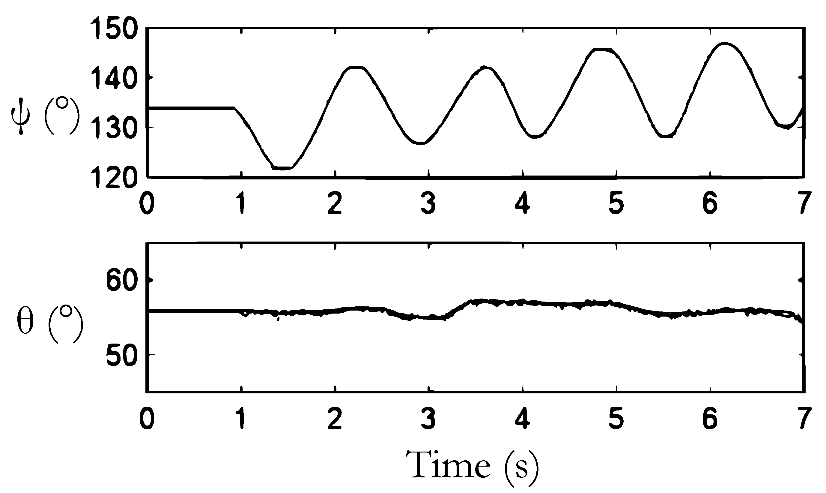
Figure 1b. The orientation of the moving platform is computed via each method. Here, all sensors are calibrated by blocking the moving platform in a reference configuration. All sensors are related to acquisition card, National Instrument card, installed on a PC based controller. The self-rotation of the moving platform is chosen to be fixed to evaluate the quality of the three methods through a random trajectory by changing the orientation. This strategy aims to compare the accuracy of the computed orientation. Obviously, the angle
should be equal to zero. The joint with axis
is sealed using an elastic pin.
The orientation of the moving platform is given in
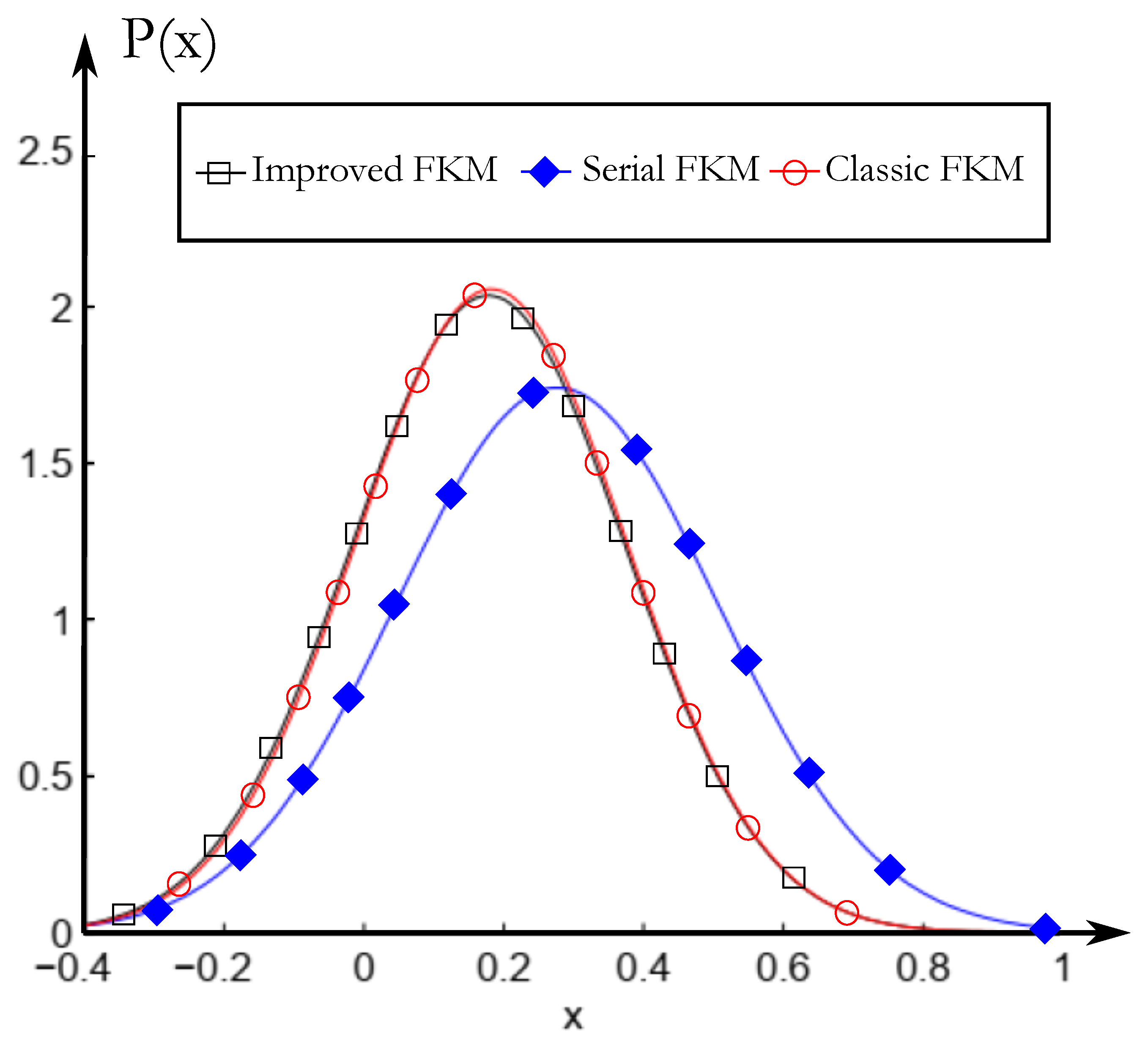
Figure 10. The self-rotation is equal to zero and if there is possible deviation, then the FKM presents an error. In order to deeply investigate these models, the error distribution is computed for each method and as a result we obtained the curves in
Figure 11. One observes that the serial FKM is the less accurate method but with no significant gap.
The
Table 2 shows the parameters of the distribution of each model. The mean value of the distribution corresponds to the calibration errors and the standard deviation corresponds to sensitivity of the model related to the sensor errors. The errors of the improved FKM and the classical FKM are very close because there is no parallel singularity in the workspace of new SPM. With no change in the control system, the serial FKM presents a suitable solution to offer a better computation time despite its loss of accuracy.
On the one hand, the serial FKM requires the use of only three sensors as the case of the classical one, therefore, no additional cost is required. Furthermore, its computing time is six times less than the classical method which leaves a lot of room for the haptic calculation. On the other hand, it is true that the serial method is the least precise, however, it is important to mention that this method is used in existing tele-operation systems with spherical serial master devices such as the “da Vinci” surgical robotic system [
21] and the master device designed by Van den Bedem et al. [
3]. The precision of the serial method can be enhanced by improving the calibration procedure. This subject will be carried out in future works.
6. Experimentation Using the TeleOperation System
6.1. Motion Control Model
The master device is designed to control the motion of the surgical robot. The motion control scheme is presented in
Figure 12. The main control unite is a PC Station. An application was developed to calculate the orientation of the new master device using the sensor data collected using an acquisition card. Then, the corresponding slave orientation is determinate using a transformation method [
22]. Finally, the slave active joint motions are solved using the Inverse Kinematic Model of the slave robot. The slave data are transferred to a PLC (the Galil(c) Controller) which controls in real-time the motion of the slave robot.
The Serial Forward Kinematic model of master was implemented in the application. An experimental validation of the control is described in the next paragraph.
6.2. Experimental Test
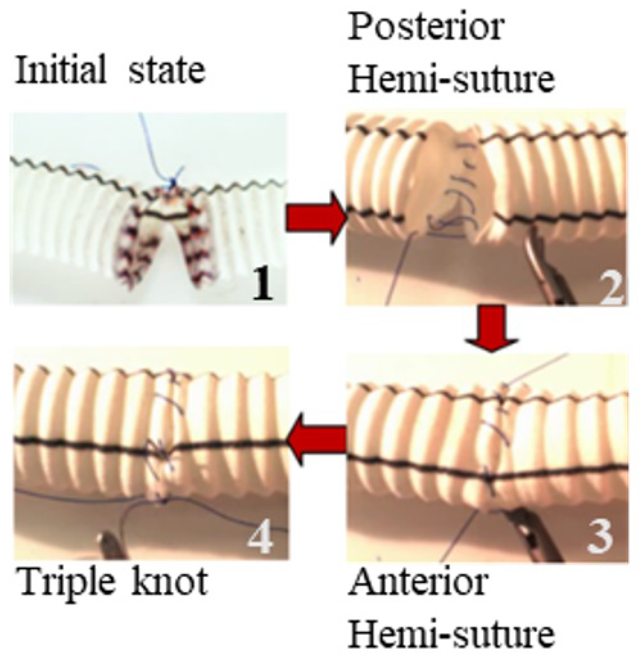
The tele-opertation system is composed of two master devices and two surgical robots. The experiments involved using the teleoperation system to perform sutures on a hollow model simulating a human artery (
Figure 13). The suturing method, called anastomosis, consists on the surgical union of two separated hollow organs. The technique is made of three phases beginning by the suture of the back hemisphere, the suture of the front hemisphere and the triple knot, respectively.
Figure 14 shows these three phases on a prosthetic aorta.
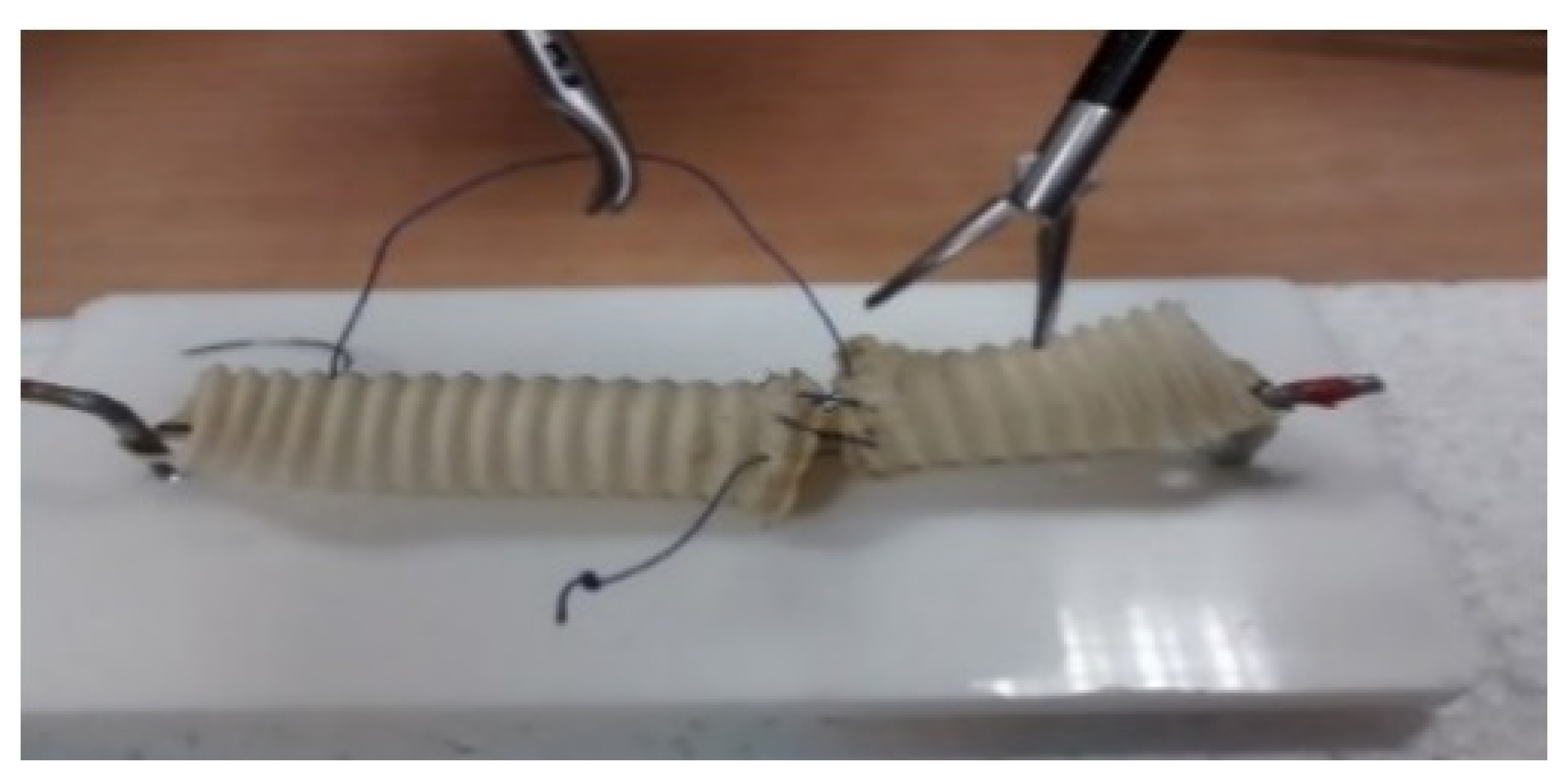
The expert surgeon manipulated the master device to control the surgical robots and to handle the needle (
Figure 15). It took some time for the surgeon to adapt to the use of the system and to acquire spatial depth perception using the 2D screen.
The surgeon was able to perform sutures using the teleoperation system as shown in
Figure 16. The use of the robot made the procedure more comfortable for the surgeon. The surgeon reports, after the first experimentations, that the proposed system presents more efficiency than other existing systems. This is coming from the fact that no training session is requested. The system is handled promptly. The operating behavior does not change, and the surgeon manipulates in case of the proposed system instruments as a classic operation. The portability of the system is coming from the fact that no need to any infrastructure modification. The whole system is fixed on a table. In addition, the small size and the ergonomics of the developed tele-operation system make distance surgical operations possible.
The duration of the suturing experiments at first experimentation is greater than one of the classic operations (manual procedure without the use of tele-opreation robots) and will be optimized in future experimentation. Forthcoming work in collaboration with surgeons will be focused on the definition of performance criteria to evaluate the suturing. The suturing quality seems to be satisfactory for preliminary experimentation using the master/slave system and will be enhanced for the future version.
The expert surgeon highlighted some enhancements. Firstly, the choice of a parallel spherical structure for the master devices is the most appropriate because of the required motion and its rigidity. However, the self-rotation was slightly limited in border regions of the workspace. Secondly, the placement of the two surgical robots needs adjustment for better needle handling. This issue will be solved by the development of adjustment robotic system in future work. Thirdly, the surgeon proposed that the closing pressure force of the instrument may be increased to make the handling more stable. Finally, the slave surgical robot was close to its singular region. The issue is due to the non-optimal placement of the robot and its reduced workspace. Some modifications are therefore being carried out to develop a second prototype of the tele-operation system that meets the requirement of the surgical gestures.
In addition, the expert surgeon did not raise any problems related to a possible lack of the FKM accuracy. However, this issue is complex since it depends on the surgeon experience, the master device as well as the visual feedback. Future work will focuses on the quantification of the accuracy for the surgical operation using the proposed tele-operation systems.


