1. Introduction
Improvement of the machine-building industry is directly related to the development of new mechanisms and machines. Their efficiency and functional properties largely depend on the kinematic schemes on the basis of which they are designed. Structural synthesis, which is one of the basic subdisciplines of mechanisms and machines science (MMS), not only allows for creating fundamentally novel mechanical systems but also ensuring their efficiency already at the stage of designing their kinematic schemes. There are various methods and algorithms for structural synthesis, including those methods that are based on graph theory [
1,
2], on the use of closed multi-degree-of-freedom (DoF) kinematic chains [
3], on screw theory [
4,
5], on the application of mobility formulas [
6,
7]. The method of sequential coupling of kinematic chains (structural groups) with zero DoF is quite widely used [
8]. This method had been firstly proposed by Assur L.V. and formulated by him for planar mechanisms. In these mechanisms, all coupled zero DoF kinematic chains (Assur groups) are placed in one or several parallel planes. This principle is kept both for mechanisms with sequential structure and for parallel mechanisms [
9,
10,
11]. In [
12], a related approach is demonstrated for developing complex screw mechanisms.
However, the coupling of exclusively planar kinematic chains, including chains with zero DoF, is quite particular case in mechanisms synthesis. Due to the fact that kinematic chains can be designed with different types of imposed constraints, various cases of their coupling are possible. For example, planar kinematic chains can also be coupled with spherical or wedge chains that have three imposed constraints like planar chains, but the type of these constraints is different [
13]. The main criterion for such a coupling is the coincidence of the movements of combined kinematic chains. In the absence of even one common movement, the joint functioning of these chains in one mechanism cannot be realized. Such a case is, for example, the combination of a spherical chain having rotations of links around each coordinate axis and a wedge chain having translational displacements of links along each coordinate axes. Because these kinematic chains lack any common movement, it is impossible to achieve their joint functioning in one mechanism.
At the same time, mechanisms that include different types of kinematic chains allow implementing fundamentally new motion laws and performing novel technological operations. Such mechanisms have all the design advantages of kinematic chains on the basis of which they are constructed. This study aims to develop and analyze a novel mechanism, which simultaneously includes planar and spatial kinematic chains. In this case, the condition of assuring the minimum number of links, kinematic pairs and drives while having spatial movement of an end-effector in the synthesized mechanism is made.
This paper is organized as follows.
Section 2 provides structural synthesis and analysis of the developed linkage mechanism in terms of kinematic chains included in its composition.
Section 3 presents an analytical solution of kinematics of the synthesized mechanism.
Section 4 shows a numerical calculation of the kinematic parameters when setting different pitches in screw joints.
Section 5 considers the creation of a CAD model of the synthesized mechanism and fabrication of its physical prototype.
Section 6 presents possible practical applications when performing specific technological operations. Conclusions are discussed in
Section 7.
2. Structural Synthesis and Analysis of the Mechanism
Address to the development of the proposed linkage mechanism and specify the synthesis conditions in the following formulation:
Provide a single drive in the mechanism (i.e., provide mobility one, W = 1) and reproducing the spatial cyclic motion of the end-effector. Accept screw motion as the output motion, in which simultaneous rotation and translational displacements are realized;
Provide the minimum number of links and kinematic pairs in the mechanism. Accept the condition that each link will be double-paired, i.e., forming only two kinematic pairs with the other links. Accept only one-DoF joints, providing speedwork and reliability when transmitting movements among links of the mechanism;
Provide the position of maximum number of movable links of the mechanism in one or several parallel planes to minimize dynamic loads during its operation.
Determine structural parameters for planar and spatial kinematic chains according to the synthesis conditions. For the planar kinematic chain, these parameters can be found from the following mobility formula
where
W is the mobility of a kinematic chain, defining the number of its DoF;
n is the number of movable links;
p5 and
p4 are the numbers of one- and two-DoF kinematic pairs.
Accepting W = 0 (necessary criterion for a kinematic chain with zero DoF) and using only one-DoF joints, the simplest solution from (1) is n = 2, = 3 and = 0. Take dyad RRP as a planar kinematic chain based on the obtained solution.
Chose helical kinematic chain as a spatial one because it could be created with minimum number of links and includes only one-DoF joints. The structure of screw kinematic chains is described by the following mobility formula
from which, with
W = 0, the simplest solution is
n = 1 and
p5 = 2. This condition corresponds to a one-bar kinematic chain (monade). Thus, governing Equations (1) and (2) allow defining structural parameters for targeted kinematic chains, including zero DoF chains when
W = 0 or mechanisms with various DoFs when
W possesses values of positive integers.
Further, sequentially couple with the driving link dyad
RRP, and then screw monade. The position of screw monade in the mechanism is provided in such a way that its translational displacement coincides with the translational displacement of dyad
RRP. The mechanism designed in this way is shown in
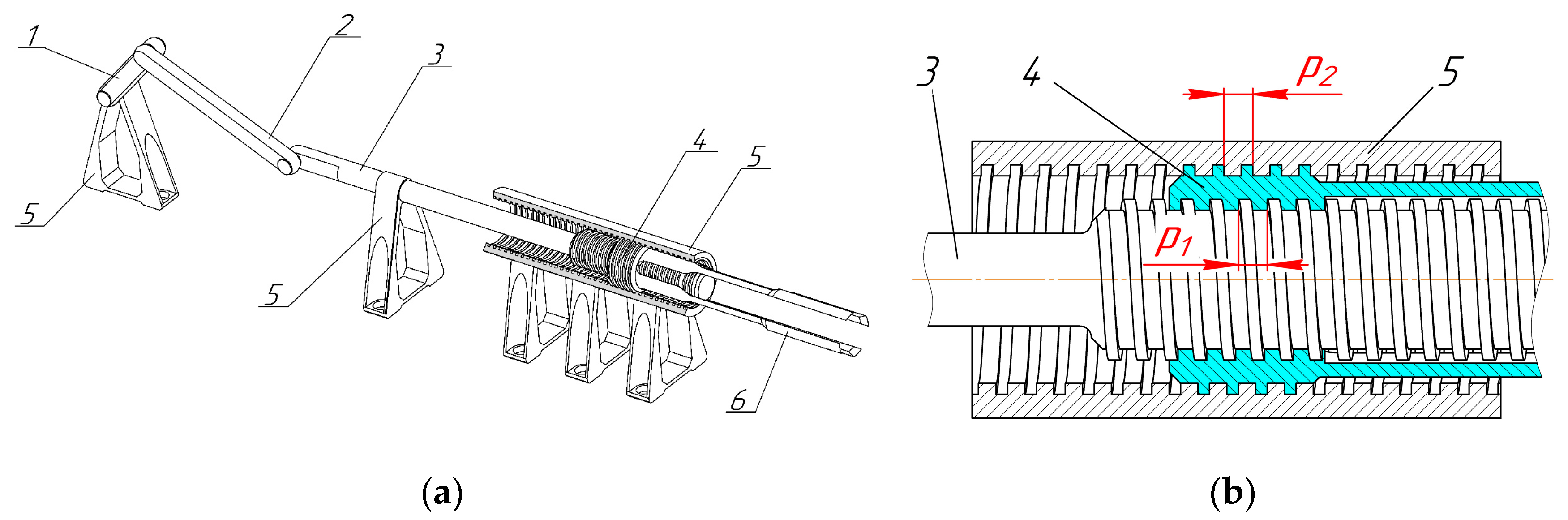
Figure 1a. Here, 1—crank (driving link), 2—connecting rod, 3—slider, 4—nut (end-effector), 5—fixed link, 6—function element integrated with nut 4. Kinematic pairs 5-1, 1-2 and 2-3 are rotational with parallel axes. Kinematic pair 3-5 is prismatic. Kinematic pairs 3-4 and 4-5 are screw.
Figure 1b shows the elements of screw part of the synthesized mechanism where pitch
p1 is in pair 3-4 and pitch
p2 is in pair 4-5.
The input movement is given to crank 1 and transmitted through connecting rod 2 to slider 3, which forces end-effector 4 to reproduce an output helical movement. A specific constructive condition in the mechanism is in providing non-self-braking of its links in kinematic pairs 3-4 and 4-5, when the helix angle (ψ) must be greater than the reduced friction angle (µ), i.e., ψ > µ, where ψ = arctg(p·k/π·d), p is the thread pitch, k is the number of starts in the screw part, d is the diameter of screw link, µ = arctg(), is the superficial friction factor in thread, = f/cos(γ), f is the friction coefficient, γ is the tilt angle of a thread flank.
3. Kinematic Analysis of the Mechanism
Address to the kinematics analysis of the synthesized linkage mechanism. There are different methods of kinematic analysis of mechanisms having screw joints [
14,
15,
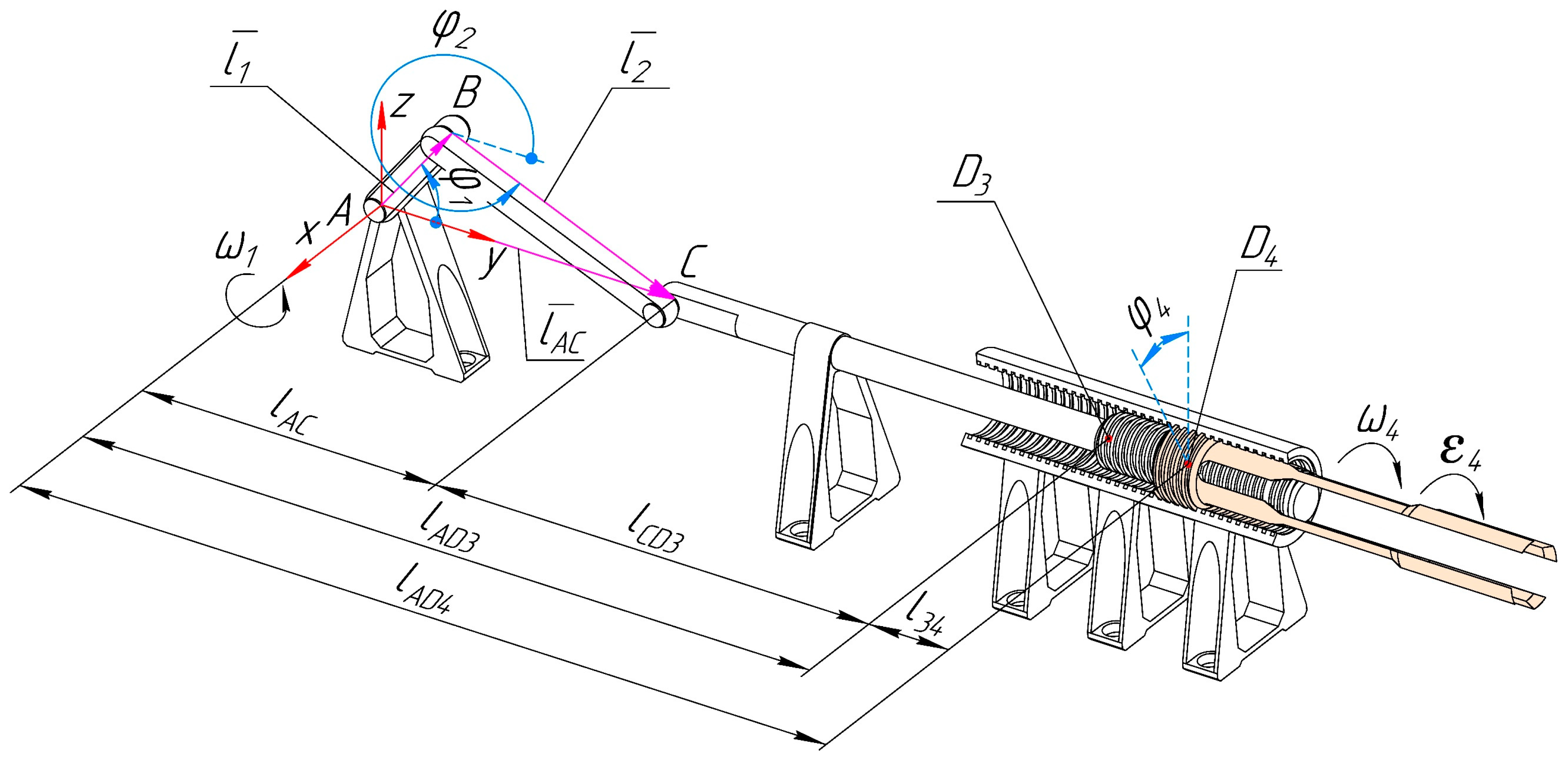
16]. Present the crank-slider part of the synthesized mechanism as closed contour
ABCA (
Figure 2), described by the vector sum:
Projecting vector Equation (3) on axes
y and
z obtains:
where
is the length of crank 1,
is the length of connecting rod 2,
is the rotational angle of crank 1,
is the rotational angle of connecting rod 2.
Express
from the second Equation of system (4) in the following view:
Variable length
can be found from the first Equation of system (4) with consideration of Equation (5) as:
Define expressions for determining linear velocity of point
C (
) and angular velocity of connecting rod 2 (
) by differentiating the Equations of system (4) with respect to generalized coordinate
:
where
and
are the analogs of linear and angular velocities.
Express parameter
from the second Equation of system (7) as:
and, introducing it into the first Equation of system (7), express the analog of linear velocity (
) as:
The true values of linear velocity of point
C (
) and angular velocity of connecting rod 2 (
) can be determined as:
Then, find linear acceleration of point
C (
) and angular acceleration of connecting rod 2 (
) by differentiating the Equations of system (7) by generalized coordinate
:
where
and
are the analogs of linear and angular accelerations.
Express parameter
from the second Equation of system (11) as:
and introduce it into the first Equation of system (11) and then express parameter
as:
The true values of linear acceleration of point
C (
) and angular acceleration of connecting rod 2 (
) are determined as:
where
and
are the given angular velocity and acceleration of crank 1.
Displacement
of point
belonging to slider 3 and locating at the beginning of its threaded part, is determined as
, where
is the length that is determined from (6),
is the constant length that is constructively given. Angle
, which determines the rotation of nut 4 relative to slider 3, is determined as:
where
is the displacement change of slider 3,
is the pitch between the screw part of slider 3 and nut 4,
is the pitch between nut 4 and the screw part of fixed link 5.
Displacement
of point
, belonging to nut 4 and locating at its center, is determined as:
where
is the variable length that determines the displacement of nut 4 relative to slider 3,
, where
is the constant length that indicates initial displacement of nut 4 relative to slider 3,
is the displacement of nut 4 per its rotation,
or
.
Due to the screw movement of nut 4, it has velocities and accelerations in two planes: linear (
,
) in plane
yOz and radial (
,
) in plane x
Oz, where angular components (
,
) also appear. These parameters are determined from the following expressions:
where
is the diameter of nut 4.
4. Results and Discussion
To determine the numerical values of variable parameters, accept the following values of the constant parameters: rotation speed of crank 1, = 5 rpm at constant angular velocity ( = const); the length of crank 1, = 0.07 m; the length of connecting rod 2, = 0.135 m; the length of the screw-free part of slider 3, = 0.25 m; constant length = 0.025 m; the diameter of nut 4, = 0.024 m.
It becomes possible to obtain the motion trajectories of the end-effector (nut 4) that differ in curvature and twisting when setting different values of screw pitches and , while having unchanged slider-crank part of the mechanism. Address to calculate the numerical values of the variable parameters of the end-effector (, , , , , , ) considering different values of pitches and . Parameters and change in proportion to parameters and . Therefore, the determination of the functions of parameters and can be neglected. Discuss three cases of screw pitches combination:
When , particularly { = 5 mm, = 5 mm}.
When , particularly { = 5 mm, = 10 mm}, { = 8 mm, = 14 mm}, { = 10 mm, = 20 mm}, { = 10 mm, = 30 mm}, { = 25 mm, = 30 mm}.
When , particularly { = 10 mm, = 5 mm}, { = 14 mm, = 8 mm}, { = 20 mm, = 10 mm}, { = 30 mm, = 10 mm}.
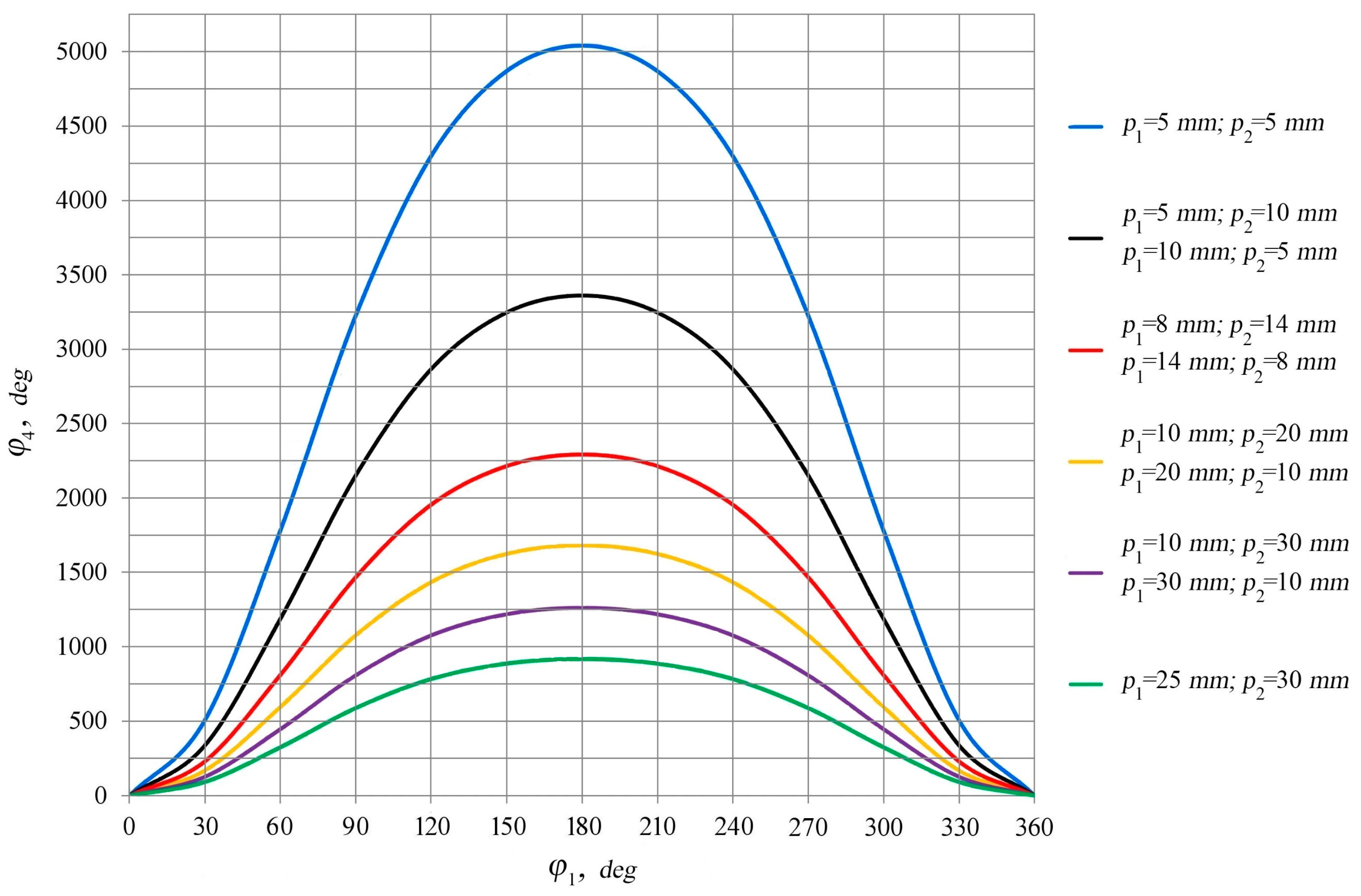
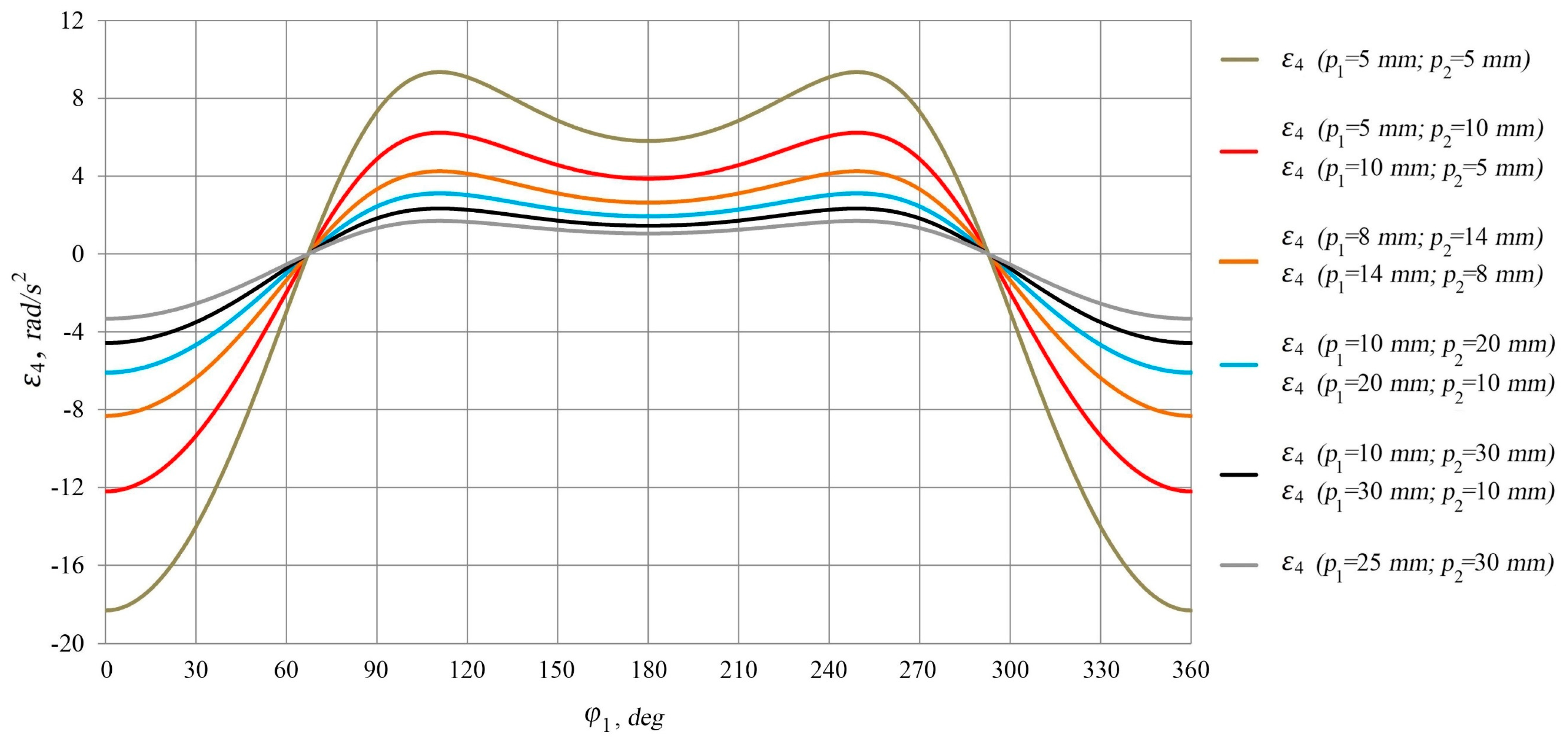
Figure 3,
Figure 4 and
Figure 5 show the diagrams providing the variation of angular parameters of nut 4 (
and
) depending on the rotational angle of crank 1 (
). It follows from
Figure 3,
Figure 4 and
Figure 5 that the angular parameters have the maximal values at screw pitches
= 5 mm,
= 5 mm, while their minimal values are realized at screw pitches
= 25 mm,
= 30 mm. The identical angular parameters are realized at the following screw pitches: {
= 5 mm,
= 10 mm} and {
= 10 mm,
= 5 mm}; {
= 8 mm,
= 14 mm} and {
= 14 mm,
= 8 mm}; {
= 10 mm,
= 20 mm} and {
= 20 mm,
= 10 mm}; {
= 10 mm,
= 30 mm} and {
= 30 mm,
= 10 mm}. This is due to the fact that nut 4 moves over the identical path along a helical trajectory for the same time period. The maximal value of the rotational angle of nut 4 (
) is realized at
= 180° for all diagrams shown in
Figure 3.
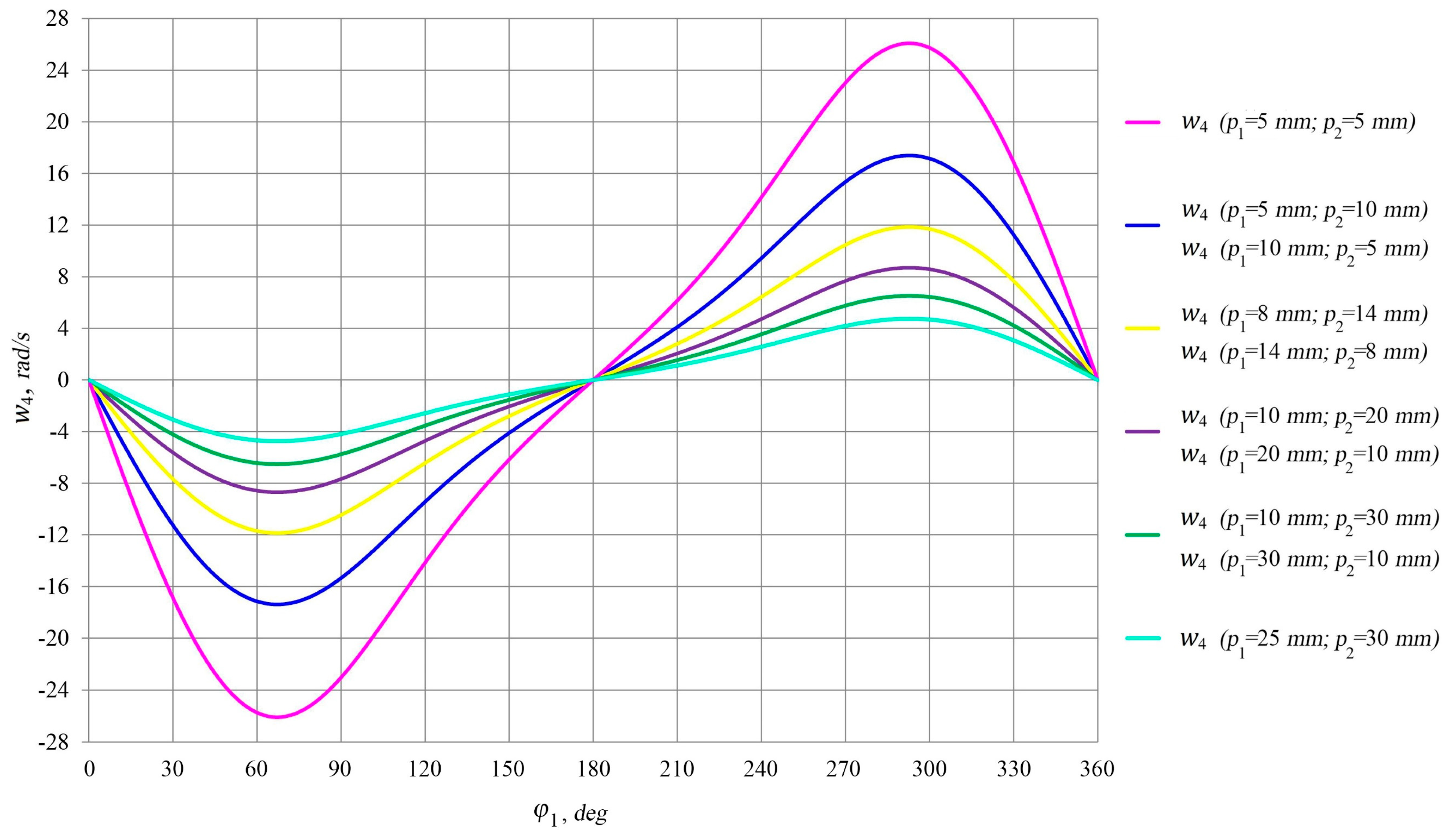
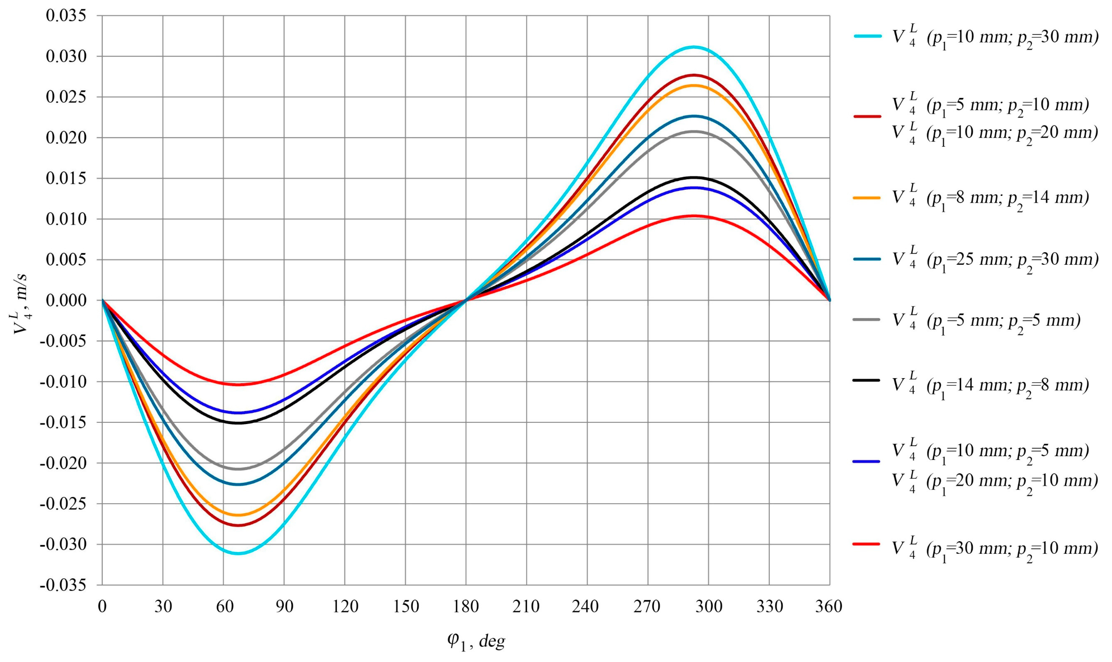
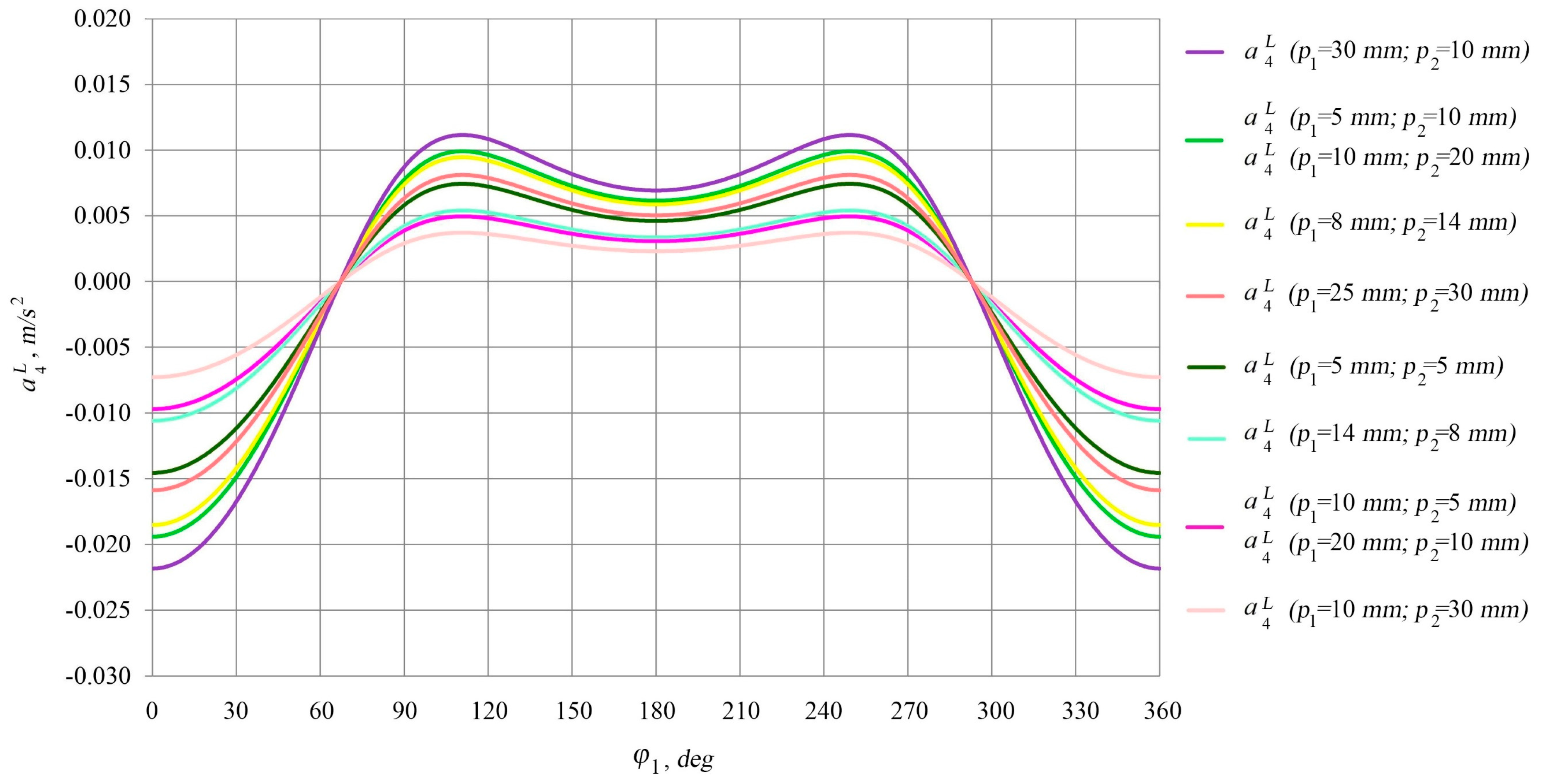
Figure 6 and
Figure 7 show the diagrams providing the variation of linear velocities (
) and accelerations (
) of nut 4 depending on the rotational angle of crank 1 (
). The maximal linear velocity is realized at screw pitches
= 10 mm,
= 30 mm, and the minimal linear velocity is at screw pitches
= 30 mm,
= 10 mm. Conversely, the maximal linear acceleration is realized at screw pitches
= 30 mm,
= 10 mm, and the minimal acceleration is at screw pitches
= 10 mm,
= 30 mm. The identical linear velocities and accelerations of nut 4 are realized at the following screw pitches: {
= 5 mm,
= 10 mm} and {
= 10 mm,
= 20 mm}; {
= 10 mm,
= 5 mm} and {
= 20 mm,
= 10 mm}. This is due to the identical functions
(
) and
(
), which determine the displacement of nut 4.
It follows from
Figure 4 and
Figure 6 that the maximal values of the angular and linear velocities (
,
) of nut 4 are realized at
= 67.2° and
= 292.8° at zero accelerations (
= 0,
= 0). From
Figure 5 and
Figure 7, it follows that the maximal angular and linear accelerations (
,
) of nut 4 are realized at
= 0° and
= 360° at zero velocities (
= 0,
= 0).
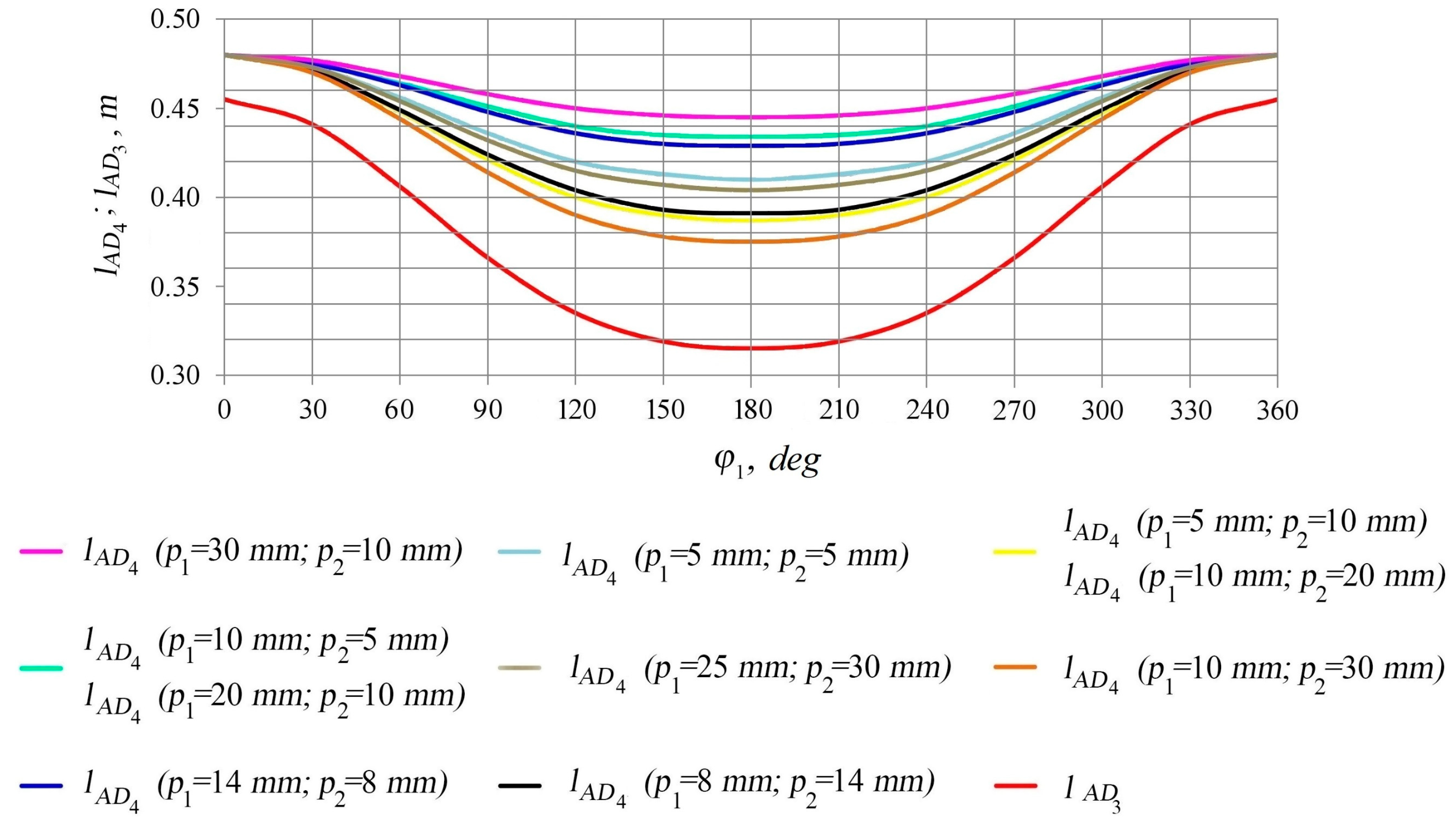
Figure 8 provides the displacement diagram of slider 3 relative to fixed link 5 (
) and the displacement diagrams of nut 4 relative to fixed link 5 (
) depending on the rotational angle of crank 1 (
). The maximal value of
is realized at
= 0° and
= 360° for all diagrams.
Figure 8 also provides the displacement of nut 4 relative to slider 3 (
), determined by the distance from the lower diagram (
) to the corresponding upper diagram (
). The maximal value of
is at
= 180° for all diagrams, and the largest value of
is when screw pitches
= 30 mm,
= 10 mm.
Numerical calculations have been carried out to verify the obtained analytical results. The CAD model of the synthesized linkage mechanism has been developed (
Figure 9) for this purpose. This model allows to simulate the trajectories of end-effector (nut 4) at different screw pitches
and
. The obtained trajectories are presented in
Figure 10. Each trajectory is a helix, where the length along axis
y is simultaneously determined by both parameters
and
, and the pitch of the trajectory is determined exclusively by parameter
. The results of the numerical calculation have completely confirmed the obtained analytical data.
The motion trajectories presented in
Figure 10 clearly demonstrate the effect of screw pitches in helical kinematic pairs 3–4 and 4–5 on the nature of end-effector’s movement. The possibility of combining the screw pitches in both pairs allows taking into account additional parameters of the end-effector’s trajectories for a given technological operation.
5. Development of an Assembling CAD Model and a Physical Prototype of the Mechanism
The detailed assembling CAD model of the synthesized mechanism has been created based on its kinematic scheme. The creation of the CAD model aims a fabrication of an actuated physical prototype on its basis.
Figure 11 presents this model, including the following elements: 1–4 are horizontally located elements of the fixed link; 5–8 are vertically located elements of the fixed link for setting motor 13, elements of crank 14 and 15 and slider 17; 9 and 10 are vertically arranged elements of the fixed link for setting elements 11 and 12, which are made with internal thread; 16 is connecting rod; 18 is screw; 19 is nut (end-effector). The dimensions of the CAD model fit with the dimensions of the mechanism indicated in
Section 4 when
= 25 mm,
= 30 mm.
The actuated physical prototype of the synthesized mechanism has been fabricated based on the assembling CAD model shown in
Figure 11.
Figure 12a presents the manufactured elements of the double screw joint—the screw, nut (end-effector) and screw part of the fixed link. This joint is the most important coupling in the mechanism, its inaccurate manufacture can lead to links jamming and a loss of functionality of the mechanism.
Figure 12b shows the full-scale prototype, fabricated in accordance with elements 1–19 of the assembling CAD model. The operation of the physical prototype is presented in the movie in
Supplementary Materials. The drive for the prototype has been chosen based on the calculation of the counterbalance moment on the driving link. Such a calculation has been carried out with consideration to reactions and friction forces acting in all kinematic pairs of the mechanism. With respect to threads in the screw joints, multi-turn threads could also be used to reduce forces in these joints and provide a higher load capacity of the end-effector. However, the assembled physical prototype smoothly operates with a single-turn thread.
A comparative analysis of the displacements of certain points of movable links of the CAD model (
Figure 11) and the physical prototype (
Figure 12) has been carried out to evaluate the accuracy of manufacturing the prototype. The displacements
of point
belonging to slider 3 and the displacements
of point
belonging to nut 4 (end-effector) have been studied.
Table 1 presents the numerical values of these parameters in twelve positions of the mechanism.
Table 2 summarizes the data on the divergence between the displacements of slider 3 (
) and nut 4 (
) of the CAD model and the physical prototype.
It follows from
Table 2 that the maximal value of
is 0.74% at
= 300°, and the maximal value of
is 0.88% at
= 60°. The occurrence of divergences
and
is associated with inaccuracies during the manufacture of mechanism elements by means of three-dimensional printing from polymeric materials. However, achieving divergences of
and
less than 1% is thoroughly acceptable, taking into account the complexity of the double screw kinematic pair and fabrication of mechanism elements from polymeric materials.
6. Possibilities of Technological Application of the Mechanism
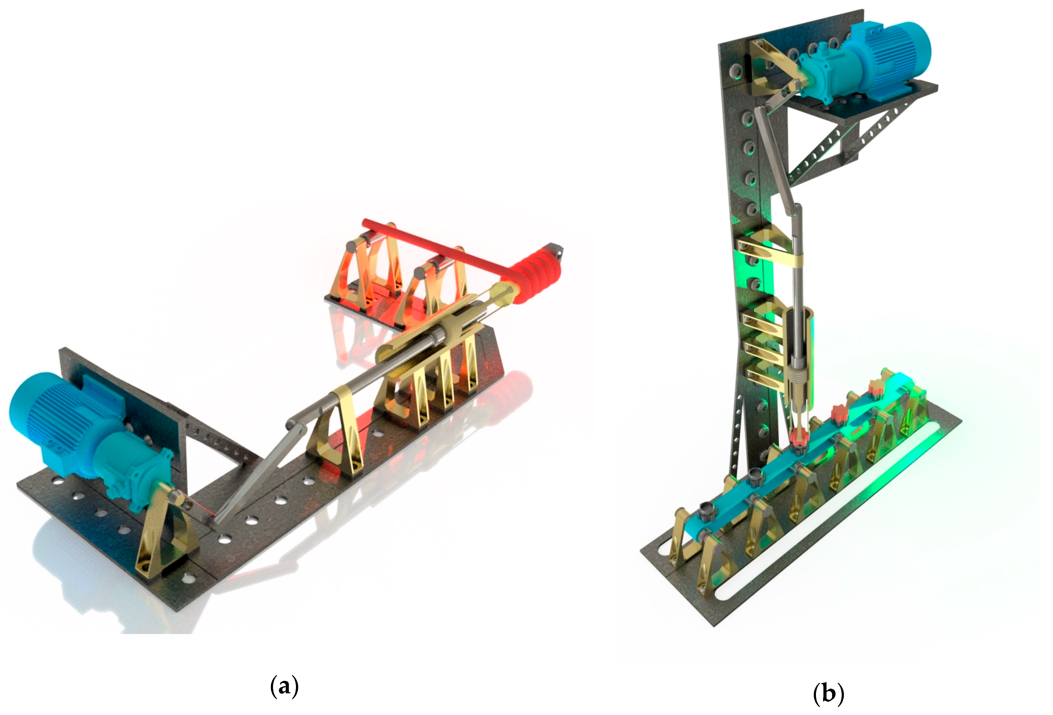
The possibilities of the practical application of the synthesized mechanism have been considered in this study. Virtual models for performing specific technological operations have been developed based on the mechanism’s kinematic scheme. Specifically, the mechanism can be used for large-diameter springs’ winding.
Figure 13a shows a virtual model where a spring is wound onto a mandrel that simultaneously becomes displaced and rotates at predetermined distances and angles. Here, the wire is moved through the rollers mounted on the fixed link, and the end of the wire is fixed on the mandrel, which is rigidly connected to the end-effector of the mechanism. The velocity of the mandrel is controlled by the driving link of the mechanism and is in the range of 10–40 m/min depending on the diameter of the wire. After the driving link moves to the end position, the winding process ends and the spring is removed. After that, the driving link makes the remaining half of a revolution and the mandrel is shifted to its initial position to perform the next operation.
The helicoidal motion of the end-effector of the synthesized mechanism allows using it to screw various objects [
17]. A virtual model of such a technological unit is shown in
Figure 13b, where the developed mechanism is located vertically. It allows screwing objects moving under the end-effector on which the gripper is set. The linear displacement and rotation of the gripper are determined by the kinematic parameters of the mechanism. The screwing is realized in a time equal to half of the driving link rotation. During the second half of the driving link rotation, the next object is placed under the gripper and the operation is repeated.
The practical application of the synthesized mechanism is not limited to the proposed technological units shown in
Figure 13. The mechanism can also be implemented for other operations that require the cyclic movement of the end-effector along a helical path. Such operations may also include mixing processes, cleaning inner cylindrical surfaces, etc.


