Article

Real-Time Cable Force Calculation beyond the Wrench-Feasible Workspace

Chair of Mechatronics, University of Duisburg-Essen, Forsthausweg 2, 47057 Duisburg, Germany
*
Author to whom correspondence should be addressed.
Robotics 2020, 9(2), 41; https://doi.org/10.3390/robotics9020041
Submission received: 31 March 2020 / Revised: 15 May 2020 / Accepted: 19 May 2020 / Published: 27 May 2020
(This article belongs to the Special Issue Theory and Practice on Robotics and Mechatronics)

Abstract

:
Under special circumstances, a cable-driven parallel robot (CDPR) may leave its wrench-feasible-workspace. Standard approaches for the computation of set-point cable forces are likely to fail in this case. The novel nearest corner method for calculating appropriate cable forces when the CDPR is outside of its wrench-feasible-workspace was introduced in former work of the authors. The obtained cable force distributions aim at continuity and generate wrenches close to the desired values. The method employs geometrical operations in the cable force space and promises real-time usability because of its non-iterative structure. In a simplified simulation, a cable break scenario was used to carry out more detailed testing of the method regarding different parameters, a higher number of cables, and the numerical efficiency. A brief discussion about the continuity of the method when entering the wrench-feasible-workspace is presented.

1. Introduction

Cable-driven parallel robots (CDPR) are in the focus of current research [1,2] and are also starting to make their way into industrial applications, see e.g., [3]. Such a robot is driven by cables, which are coiled on computerized winches and attached to an end-effector, following the kinematic structure of a Stewart–Gough platform. This allows for immensely large workspaces, as the cables can be prolonged easily.
As a cable is a unilateral constraint and can exert forces only in pulling direction, the workspace cannot be determined adequately by using purely kinematic models. Therefore, the cable tensions play an essential role in typical workspace criteria for CDPRs. The wrench-feasible workspace WFW includes all end-effector poses, where a desired wrench w at the platform can be produced by a set of cable forces f within defined boundaries [4].
In typical applications, all planned maneuvers take place in the WFW and therefore plenty of well-known methods exist to determine suitable cable forces, see e.g., [5].
However, in special situations, the end-effector can get outside of the WFW and no cable forces f can be found that generate the desired wrench w . This might occur e.g., in haptic interaction, when the imprinted external forces and torques exceed the adjustable values. Furthermore, it can occur in the critical situation of a cable-break, when a cable is suddenly absent and the robot cannot generate the desired wrench. These situations have been further discussed e.g., in [6,7].
To operate the robot outside of its WFW and—in the example of a cable break—guide it back into the WFW , methods are required, that find reasonable forces which produce the possibly closest wrench with respect to the desired values.
In [8], a strategy for moving the cable robot safely after cable failure is proposed, using motion planning along a straight line path. The authors of [9,10] propose three methods to recover the platform wrench after a cable failure. The first methodology is based on the projection of a lost wire force onto the orthogonal complement of the null space of the Jacobian. Both remaining methods minimize the norm of the overall and the correctional cable force vectors, respectively, based on a Lagrange multiplier method. Note that Notash only refers to applications in the wrench-closure workspace, which is defined as in [11]. In [12], an optimization based method is presented to compute suitable forces outside the WFW using a so-called slack variable. However, as the solution of the resulting problem is iterative, the method might have computation time issues regarding the operation in a real-time control system.
To close the gap between the proposed methods, the nearest corner method was developed and introduced in former work of the authors [6]. It is a real-time suitable method that allows for operation outside the WFW and also the consideration of path-planning and collision avoidance.
The method is based on geometrical calculations inside the cable force space. It offers a defined and predictable number of non-iterative calculation steps, which promises a high suitability for real-time applications.
In [6], an example of a rescue scenario after a cable break was used for testing the nearest corner method. More details regarding the scenario and robot model can be found in [7]. The simulation model possessed three cables and two degrees of freedom and a redundancy of r = 1 . Simulation results have been shown in [6], comparing different parameters, which will be briefly discussed in Section 4.2.
However, as the the results of former work have been promising, there are open questions left that need to be discussed in this paper. First, broader testing with different parameters and tests in a model with a higher redundancy of r = 2 need to be carried out. Second, a detailed investigation on the computation time as well as on real-time suitability is needed. Finally, the continuity of the method when leaving or entering the WFW needs to be discussed.
The paper is structured as follows: In the second chapter, an introduction of the underlying robot-modeling is given and the computation of cable forces is explained. The third chapter outlines two methods for calculation cable forces outside of the WFW . In chapter four, open questions regarding the nearest corner method are addressed via the results of the simulation. Chapter five summarizes the results and gives an outlook on future work.

2. Modeling and Cable-Robot Basics

The robot, as shown in Figure 1, is referenced in the inertial coordinate-system Robotics 09 00041 i002, where the mobile platform carries the platform-fixed coordinate-system Robotics 09 00041 i001
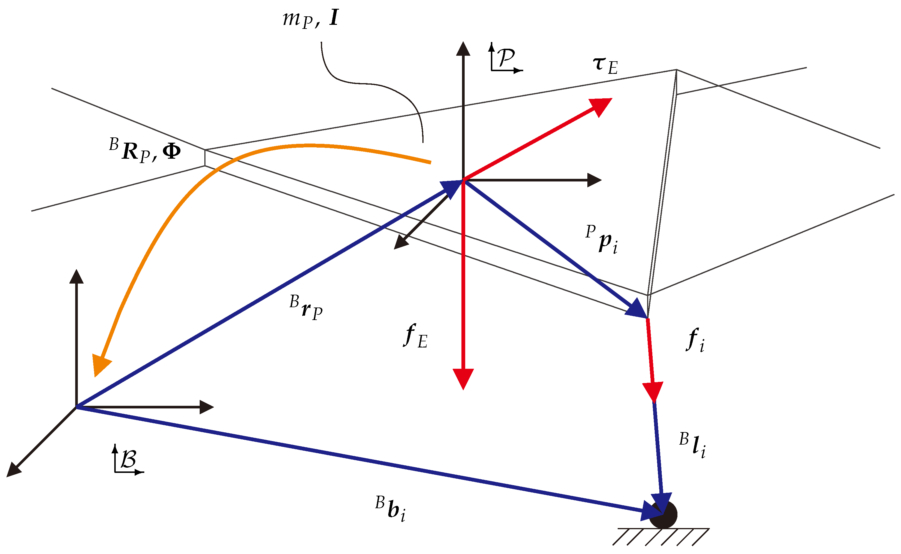
. The robot possesses n degrees-of-freedom and m cables. Therefore, the redundancy of the platform is r = m n . The posture of the platform—which here is the end-effector of the robot—referenced in coordinates of the inertial frame is defined as B x P = [ B r P Φ ] T . Herein, B r P is the position vector and Φ the orientation of the end-effector, both defined as row vectors. The orientation with respect to the inertial coordinate-system is described in the means of roll-pitch-yaw angles by the rotation matrix B R P . Assuming a point-shaped guidance of the cable at the point where the cable is leaving into the workspace, the modeling of pulleys is neglected in the following. Using inverse kinematics, the cable vectors B l i , as shown in Figure 1, can be obtained by:
B l i = B b i ( B r P + B R P P p i ) B p B i , 1 i m
Herein, B b i are the base vectors of the robot and describe the points, where the cables enter the robot’s workspace. P p i describe the points where the cables are connected to the platform.
In the following, all vectors are decomposed and referenced in coordinate system Robotics 09 00041 i002, whereas for simplicity, the top-left index is left out.
Every cable is tensioned by a force f i in direction of the unit vector ν i . All cable tensions are merged into the cable force vector f R m × 1 . The i th cable exerts the force f i on the platform, that is
f i = f i · l i l i 2 = f i · ν i , 1 i m .
A T is the structure matrix of the robot. All forces and torques acting on the end-effector except for the cable forces are summarized in w . This might include gravity, process forces and torques as well as inertia. Accordingly, in force equilibrium it holds
w = f p τ p = ν 1 ν m p 1 × ν 1 p m × ν m f 1 f m = A T f .
Setting up Newton–Euler equations, it is assumed that the center of gravity is identical to the origin of the end-effector coordinate system [13]. Considering a simplified model for force equilibrium (assumptions see Section 4), it holds that
m p E 0 0 I K M p ( x p ) B r ¨ P Φ ¨ x ¨ p + 0 I ( K ˙ Φ ˙ ) + ( K Φ ˙ ) × I ( K Φ ˙ ) w C ( x p , x ˙ p ) f E τ E w E w = A T f .
The wrench w must be generated by the cables, e.g., to follow a certain motion. The platform mass m p and the inertia tensor I are used to obtain the mass matrix of the platform M p . x ˙ p and x ¨ p are the first and second time derivative of the end-effector pose x p . The inertia tensor needs to be expressed in the inertial system Robotics 09 00041 i002 and depends on the orientation of the platform. E is an 3 × 3 identity matrix. Matrix K and its time derivative can be obtained from the kinematic Kardan equations [14]. w C contains the Coriolis and centrifugal forces and torques, while w E is the vector of external forces and torques acting on the platform. The presented cable-robot model and the underlying equations are based on [15].

2.1. Wire Force Distribution

Solving Equation (4), considering limited cable forces, is a known problem in the field of cable-robots. The cable forces are limited by a maximum force f max and a minimum force f min . These parameters limit both the maximum motor torque to prevent damages to the system, and the minimum cable tension to avoid sagging cables. The geometrical interpretation of the problem is one suitable way to determine force distributions [16]. A m-dimensional hypercube C R m is formed by the cable force limits inside the space of the cable forces. The delimiting hyperplanes of the cube are defined by f i = f min f i = f max , 1 i m . For n equations and m unknown variables, assuming n < m and a given w according to Equation (4), Equation (3) is an under-determined linear system of equations. The dimension of the solution space is therefore equal to the redundancy r of the robot. Solving Equation (4) for f , one has to consider:
f = A + T w f 0 + H λ .
λ R r is a vector of multipliers. The projection of the desired wrench onto the solution space is f 0 . The Moore–Penrose pseudo inverse of the structure matrix is denoted by A + T . The kernel or null space H R m × r of the structure matrix A T is defined by
H = h 1 , , h r
with the vectors h k solving the equation:
A T h k = 0 , 1 k r .
The solution space S R m , defined by the columns of the kernel H , is r-dimensional and contains all solutions of Equation (4). As shown in Figure 2, if the hyperplane intersects the solution space, all feasible wire force distributions which lie inside the force limits are included in the manifold
F = C S .
If F is nonempty for the given wrench, the pose is called wrench-feasible and F forms a convex polyhedron [16]. As shown in Figure 2, the polyhedron Λ is formed by all multipliers λ leading to wrench-feasible solutions. The kernel H is used as a transformation between R r and R m . Considering the given force limits when solving the problem in Equation (5), it holds that
f min f 0 + H λ f max f min f 0 H λ f max f 0 .
The basis for the solution space S is being formed by the kernel H of the structure matrix. If a feasible wire-force-distribution is existing, the inner tension of the system can be adjusted by scaling the force-distribution within the limits using λ Λ . There are several methods for computing force-distributions, which differ in computation time, workspace coverage, continuity, force level, maximum possible redundancy, and real-time capability [5]. The forces can e.g., be calculated as an optimization problem [17] or by applying the barycentric method [18].

3. Force Calculation Outside the Wrench-Feasible Workspace

As described in the introduction, scenarios with a non-feasible wrench might occur, e.g., when moving the end-effector outside of the static workspace using a haptic device or after a cable break [6,7]. In this particular case, the given common methods fail to operate and a solution of Equation (4) cannot be found as there is no intersection F . Therefore in the following, approaches to generate approximated, but still reasonable force distributions are given.

3.1. Optimization

In [12], a method to calculate force distributions as an optimization problem considering the constraints was proposed. Assuming the robot is outside its WFW . Simply changing the constraints of minimum and maximum cable forces in order to find an appropriate wire force distribution is no option. Therefore, to relax Equation (4), a so called slack variable s is added to the left side of the equation. In [12], a way to solve the resulting problem via quadratic programming is suggested. The optimization problem is given as
minimize s T D 1 s + ( f f ˜ ) T D 2 ( f f ˜ ) with A T f + w + s = 0 f min f f max .
To adjust the solution, the diagonal weighting matrices D 1 and D 2 can be used. The solution forces will more likely generate the desired wrench by choosing D 2 < D 1 . Otherwise, the solution will tend more to follow the target forces f ˜ . By choosing the target forces properly, the solution can be adjusted e.g., for maximum stiffness or minimum force. The iterative approach of the proposed solution method might be a problem within industrial real-time applications, even though a solution of the problem can be carried out computationally efficient as shown in [12]. Therefore it can be advisable to use a method with a preferably low and—most importantly—defined number of calculation steps.

3.2. Nearest Corner Method

In general, an optimizing algorithm as explained beforehand is applicable. But due to the fact that such optimization schemes usually employ iterative solvers, their usability in a real-time control systems might be a problem. As proposed in former work of the authors [6], an approach based on geometrical analysis within the cable force space can be used, which is briefly explained in the following. As discussed in Section 2.1, the space of cable forces f can be represented by an orthogonal coordinate system. Note, the corners of C are denoted as F E , j , j = 1 , , 2 m . In the following, it is assumed that r = 1 or r = 2 . Assuming a CDPR is within its WFW , a set of cable force solutions F exists and a continuous solution along a trajectory can be found. The methods as discussed in Section 2.1 can be applied. Still, these methods will fail, if the CDPR is outside its WFW and F is empty. Given the fact that there is no intersection of the hypercube C and the solution space S , yet both of them exist.
Now there is at least one corner of C which has the closest distance to the hyper straight line (for r = 1 ) or hyperplane (for r = 2 ) representing S , using Euclidean norm. Therein, the orthogonal projections of F E , j onto S are denoted F P , j , as shown in Figure 3. The force distribution f at the corner that has the closest distance is no solution to Equation (5). Still, it is an approximation in terms of the motion inducing parts of f , i.e., f 0 , and compliant with the force boundaries. It can be used e.g., for control purposes, accordingly.
Note, that depending on the motion of the system, this closest corner might switch instantaneously. Accordingly, instead of only using the closest corner, all corners are considered to ensure continuity of the resulting cable forces during a motion. They are weighted by the distance to S using Euclidean norm, where the distances between the projected forces onto S , namely F P , j and the corners F E , j are given by
d j = | | F P , j F E , j | | , 1 j 2 m .
To obtain proper weighting g j for each corner of C , the summarized distance L = j = 1 2 m d j is needed.
g j = L d j p
With higher exponential weights p, the corner closest to S will dominate all others the closer it gets. If C and S are about to intersect, this ensures continuous transition between force distributions outside and within the WFW , i.e., if a corner is about to become a valid force distribution according to Equation (5).
G = i = j 2 m g j is the sum of all weights and the resulting force distribution yields
f = j = 1 2 m F E , j g j G , 1 j 2 m .
In general, finding a feasible cable force distribution according to Section 2.1 is always attempted beforehand. The proposed method is used if these algorithms fail to determine a feasible solution and a cable force distribution will be found, which has minimal distance to the solution space S .

4. Simulation and Results

4.1. Evaluation for Redundancy r = 1

In former work of the authors, an example of a post cable break rescue scenario for testing the proposed method was used, which was also applied in the following. More details to the scenario and robot model can be found in [6,7]. As the results in this work extend the discussion presented there and for comparability of the results in this work, the parameters remained the same as in the cited sources. The model possessed three cables and two degrees of freedom and therefore a redundancy of r = 1 . The employed dynamic model was planar and had two degrees-of-freedom. The end-effector was subject to gravity in negative direction of the y-axis and approximated as a point mass with m p = 1 kg. The minimum force was f min = 5 N and the maximum force was f max = 150 N, respectively. The cables cannot sag and were assumed to be massless. The numbering of the cables was done in a clockwise direction, beginning with cable 1 at the bottom left and the pulley positions B are shown in Figure 4. The simulation was carried out with a numerical integration using the Euler–Cromer method and a fixed time step of Δ t = 1 ms. Based on the current cable and gravitational forces, the actual platform acceleration was computed each time step. The modeling of electric motors, gears, friction, and disturbances was neglected.
Now, a situation after a cable break was conceived. The platform was placed with zero velocity at r p = 0.35 0.5 T m, at the start of the simulation. This position was outside of the static workspace of the robot model [7]. Inside the workspace at r f = 0.65 0.5 T m, a goal position was defined, which could be a rescue position after a cable break. An attractive potential field, as introduced in [19], was placed with its origin at the goal position, to generate a desired wrench. The resulting attractive force was given by the gradient of the potential field U :
F att ( r p ) = U att ( r p ) = ζ ( r p r f ) : ρ f ( r p ) ρ 0 ρ 0 ζ ( r p r f ) ρ f ( r p ) : ρ f ( r p ) > ρ 0 .
To adjust the field strength, the scaling parameter ζ = 400 can be used. The Euclidean distance between goal and actual position was ρ f ( r p ) . The field was shifted between a quadratic and a conic potential at distance ρ 0 = 0.2 m. Additionally, a virtual damping was applied, which was proportional to the robot velocity with factor D P = 110 Ns /m. Including the external forces, the resulting wrench was
w = F E F att ( r p ) + F D P ( r ˙ p ) .
This desired wrench might be infeasible within the given cable force limits. Note, that repulsive fields can also be used to avoid collisions [7], but this is not discussed further in this work. As described in Section 3.2, a force calculation method is needed to check for a feasible solution of Equation (4). In the following, the puncture method [20] was used for this purpose. If this method found a feasible solution, the according cable forces were set in the next simulation step. If not, the nearest corner method from Section 3.2 was applied to find forces which result in a wrench close to the desired one.

4.2. The Effect of Different Exponential Weights

In [6], simulation results were shown, comparing exponential weights of p = 8 and p = 20 in terms of forces and platform movement. In the following, the effect of different exponential weights p on the platform movement was investigated in more detail. The simulation was carried out with the parameters given beforehand, and the exponential weights varied between p = 4 and p = 200 . The results are shown in Figure 4. In general, it can be observed that an overshooting of the end-effector over the goal is reduced with increasing exponential weights. This is due to the fact, that higher exponential weights p allow for a stronger intervention with cable forces nearer the dominating edge of the hypercube.
Moreover, the time to reach the goal position t end is also reduced with higher weights p. The values in Figure 4 show a significant reduction of t end in low values of p. In comparison of p = 4 and p = 10 , t end is reduced by more than a fifth. With rising p, the reduction of t end declines sharply. For p 25 , the reduction is barely noticeable. This is consistent with the changes in the movement of the end-effector, which is also barely effected by weights p 25 .
Note that exponential weights significant higher than p = 200 are not shown in Figure 4, as they caused numerical instabilities due to very high numbers. Therefore, very high exponential weights of p may be attractive in terms of continuity when entering the WFW , but are not viable or useful in a real system.

4.3. Evaluation for Redundancy r = 2

In this section, the application of the nearest corner method in an example with a redundancy of r = 2 is presented. The simulation parameters remain the same as in the example beforehand. The number of cables is increased to m = 4 and the positions of the pulleys B are shown in Figure 5. A cable break scenario is still being investigated. At the start of the simulation, the platform was placed at r p = 0.35 0.8 T m with zero velocity, which was outside of the static workspace of the robot model, see Figure 5. The goal position inside the workspace, which also possesses an attractive potential field, was set at r f = 0.75 0.75 T m. The exponential weight was set to p = 20 .
The static equilibrium workspace can be obtained neglecting dynamic effects. An approximation of the static workspace was then generated by using a point grid and solving Equation (4) for each point. A comparison of the workspace before and after a break of the top left cable is shown in Figure 5. Clearly, the robot might be outside the workspace after a cable break.
Carrying out the simulation, the results as shown in Figure 6 can be obtained. The end-effector was pulled into the goal position after about 0.07 s, but overshoots in direction of the x-axis, since a maximum speed of 7 m/s was built up. At 0.015 s a first feasible solution was found by the puncture method and the algorithm switches. At 0.04 s the end-effector leaves the WFW again and the algorithm switches back to the nearest corner method until 0.14 s. In this example it can be observed that the forces were continuous whenever the solution space and the hypercube begin to intersect or separate, respectively. Cable force limits were reached but not exceeded by the algorithm throughout the whole trajectory. The robot was successfully guided into the goal position after 0.2 s. At about 0.22 s it came to a complete stop and the cable forces were settled. Concluding, the method works for examples with r = 1 and r = 2 with higher redundancies need to be investigated.

4.4. Computational Efficiency

To test the computational efficiency, the algorithm was compiled as a MEX-file, using Matlab Coder in Matlab R2019a. The execution was carried using an Intel CPU i7-3770 with 3.4 GHz on a Windows 10 System. The scenario as described in Section 4.2 with an exponential weight of p = 8 , see [6], was used to measure the computation time.
Figure 7 displays the resulting computation time per cycle step of the simulation throughout the trajectory. Note, that the calculation time of the algorithm in the first few steps is incomparably higher due to initialization and memory preallocation. After that, in the first phase, where the nearest corner method was active, the average computation time is 54.5 μ s .
In the second phase, the algorithm switches. Now, the robot was inside the WFW and feasible solutions can be found by the puncture method, which was represented by a mean calculation time of 48.8 μ s .
The difference of 5.7 μ s in mean computation time between both phases exemplifies how small the calculation time of the nearest corner method itself is. Considering a 2 kHz control frequency which leads to 500 μ s cycle time, the Nearest Corner Method in combination with the Puncture Method for a first feasibility check, needs roughly 10% of the cycle time. All in all, this makes the method highly applicable in real-time control systems.

4.5. Continuity

To ensure a stable system operation and to avoid vibrations in the system, a continuity in the cable forces and therefore in the commanded motor torques is essential. In general, for a continuously moving solution space, the resulting cable forces are continuous. The crucial point occurs, when the solution space S starts or stops to intersect the hypercube C and the robot is entering or leaving the WFW . For exponential weights p , the solution of the nearest corner method converges against the edges of the hypercube. If the preceding feasibility check is carried out using a cable force calculation method that covers the full workspace as e.g., the barycentric method [18] or the improved closed form [21], a solution is found as long as it exists. In this case, the transition between the two methods is continuous. But as an exponential weight of p is not necessarily viable or useful in a real system as discussed in Section 4.2, there can always be a small discontinuity in the solution. Nevertheless, for time-discretized and sampled real-time systems, the effect is minor.

5. Conclusions and Outlook

A new real-time capable method for cable force calculation of CDPRs outside the WFW was discussed in this work. The method is based on geometric calculation in the cable force space. Based on former work of the authors, several open questions are addressed in this work.
Starting from the experiments in [6], a broader view to the effect of different exponential weights p was given. Also, the method was shown to work for a higher redundancy of r = 2 in an extended example simulation. As the algorithm works on geometric calculations in the cable force space and is non-iterative, it possesses superior real-time-behavior which was shown in Section 4.4. Furthermore, a brief discussion about the continuity of the method was given, when the end-effector is entering or leaving the WFW . The properties of the algorithm indicate a high relevance for situations like cable breaks or emergency stops.
Next steps involve the testing in a complex physical environment simulation and finally practical testing on a real-time system. Lastly, an implementation of the method for arbitrary redundancies needs to be done and tested.
In the future, the presented method can be a contribution to ensure the safety and reliability of cable-driven parallel robots operating beyond their WFW , e.g., after a cable break. This is highly relevant in industrial applications, such as warehousing or automated construction [1,3].

Author Contributions

Conceptualization and methodology, R.B. and T.B.; software, R.B.; validation, R.B.; formal analysis, R.B. and T.B.; investigation, R.B.; resources, T.B.; data curation, R.B.; writing—original draft preparation, R.B.; writing—review and editing, T.B.; visualization, R.B.; supervision, T.B.; project administration, T.B.; funding acquisition, T.B. All authors have read and agreed to the published version of the manuscript.

Funding

This research received funding by the Federal Ministry for Economic Affairs and Energy based on a resolution of the German Bundestag. This funding is within the project “Entwicklung von Seilrobotern für die Erstellung von Kalksandstein-Mauerwerk auf der Baustelle” (IGF Vorhaben Nr.: 20061 BG), supported by the German Federation of Industrial Research Associations (AiF).

Conflicts of Interest

The authors declare no conflict of interest.

Abbreviations

The following abbreviations are used in this manuscript:
CDPRCable-driven parallel robot
WFW Wrench-feasible workspace

References

  1. Bruckmann, T.; Mattern, H.; Spengler, A.; Reichert, C.; Malkwitz, A.; König, M. Automated construction of Masonry buildings using cable-driven parallel robots. In Proceedings of the 33rd International Symposium on Automation and Robotics in Construction and Mining (ISARC), Auburn, AL, USA, 18–21 July 2016; pp. 332–340. [Google Scholar]
  2. Izard, J.B.; Dubor, A.; Herve, P.E.; Cabay, E.; Culla, D.; Rodriguez, M.; Barrado, M. Large-scale 3D printing with cable-driven parallel robots. Constr. Robot. 2017, 1, 69–76. [Google Scholar] [CrossRef]
  3. Bruckmann, T.; Lalo, W.; Nguyen, K.; Salah, B. Development of a storage retrieval machine for high racks using a wire robot. In Proceedings of the ASME International Design Engineering Technical Conferences and Computers and Information in Engineering Conference, Chicago, IL, USA, 12–15 August 2012; pp. 771–780. [Google Scholar]
  4. Gouttefarde, M.; Merlet, J.-P.; Daney, D. Wrench-Feasible workspace of parallel cable-driven mechanisms. In Proceedings of the IEEE International Conference on Robotics and Automation (ICRA), Roma, Italy, 10–14 April 2007; pp. 1492–1497. [Google Scholar]
  5. Pott, A. Cable-driven Parallel Robots: Theory and Application. In Springer Tracts in Advanced Robotics; Springer: Berlin, Germany, 2018; ISBN 978-3-319-76137-4. [Google Scholar]
  6. Boumann, R.; Bruckmann, T. Computationally Efficient Cable Force Calculation Outside the Wrench-Feasible Workspace. In Robotics and Mechatronics, ISRM 2019, Proceedings of the IFToMM International Symposium on Robotics and Mechatronics, Taiwan, China, 28–30 October 2019; Kuo, C.H., Lin, P.C., Essomba, T., Chen, G.C., Eds.; Springer: Cham, Switzerland, 2020; Volume 78. [Google Scholar]
  7. Boumann, R.; Bruckmann, T. Simulation of Cable Breaks and Development of Emergency Strategies for Cable-Driven Parallel Robots. In Proceedings of the Fourth International Conference on Cable-Driven Parallel Robots, Krakow, Poland, 30 June–4 July 2019. [Google Scholar]
  8. Boschetti, G.; Passarini, C.; Trevisani, A. A Strategy for Moving Cable Driven Robots Safely in Case of Cable Failure. In Advances in Italian Mechanism Science; Boschetti, G., Gasparetto, A., Eds.; Springer: Cham, Switzerland, 2017. [Google Scholar]
  9. Notash, L. Failure recovery for wrench capability of wire-actuated parallel manipulators. Robotica 2012, 30, 941–950. [Google Scholar] [CrossRef] [Green Version]
  10. Notash, L. Wrench Recovery for Wire-Actuated Parallel Manipulators. In Romansy 19-Robot Design, Dynamics and Control; Padois, V., Bidaud, P., Khatib, O., Eds.; Springer: Vienna, Austria, 2013. [Google Scholar]
  11. Verhoeven, R.; Hiller, M. Estimating the Controllable Workspace of Tendon-Based Stewart Platforms. In Advances in Robot Kinematics; Lennarčič, J., Stanisic, M.M., Eds.; Springer: Dordrecht, The Netherlands, 2000. [Google Scholar]
  12. Côté, A.F.; Cardou, P.; Gosselin, C. A tension distribution algorithm for cable-driven parallel robots operating beyond their wrench-feasible workspace. In Proceedings of the 16th International Conference on Control, Automation and Systems (ICCAS), Gyeongju, Korea, 16–19 October 2016; pp. 68–73. [Google Scholar]
  13. Hahn, H. Rigid Body Dynamics of Mechanisms: 1 Theoretical Basis; Springer: Berlin/Heidelberg, Germany, 2002. [Google Scholar]
  14. Hiller, M. Mechanische Systeme: Eine Einführung in die Analytische Mechanik und Systemdynamik; Springer: Heidelberg, Germany, 1983. [Google Scholar]
  15. Bruckmann, T.; Lalo, W.; Sturm, C. Application Examples of Wire Robots. In Multibody System Dynamics, Robotics and Control; Springer: Vienna, Austria, 2013. [Google Scholar]
  16. Verhoeven, R. Analysis of the Workspace of Tendon-Based Stewart Platforms. Ph.D. Thesis, University of Duisburg-Essen, Duisburg, Germany, 2004. [Google Scholar]
  17. Bruckmann, T.; Pott, A.; Hiller, M. Calculating force distributions for redundantly actuated tendon-based Stewart platforms. In Advances in Robot Kinematics; Lennarčič, J., Roth, B., Eds.; Springer: Dordrecht, The Netherlands, 2006. [Google Scholar]
  18. Mikelsons, L.; Bruckmann, T.; Hiller, M.; Schramm, D. A real-time capable force calculation algorithm for redundant tendon-based parallel manipulators. In Proceedings of the IEEE International Conference on Robotics and Automation, Pasadena, CA, USA, 19–23 May 2008; pp. 3869–3874. [Google Scholar]
  19. Spong, M.W.; Hutchinson, S.; Vidyasagar, M. Robot Modeling and Control; Wiley: Hoboken, NJ, USA, 2005; ISBN 9780471649908. [Google Scholar]
  20. Müller, K.; Reichert, C.; Bruckmann, T. Analysis of a Real-Time Capable Cable Force Computation Method. In Cable-Driven Parallel Robots; Pott, A., Bruckmann, T., Eds.; Springer: Cham, Switzerland, 2014; Volume 32. [Google Scholar]
  21. Pott, A. An improved force distribution algorithm for over-constrained cable-driven parallel robots. In Computational Kinematics; Springer: Dordrecht, The Netherlands, 2013; pp. 139–146. [Google Scholar]
Figure 1. Model parameters of the cable-robot.
Robotics 09 00041 g001
Figure 2. Visualization of solution space, cube, manifold, and map for r = 2 and m = 3 .
Robotics 09 00041 g002
Figure 3. Projection of corners on solution space for an empty set of F , example for m = 3 , r = 2 .
Robotics 09 00041 g003
Figure 4. Situation after break of cable associated with upper left winch. Movement of end-effector with comparison of different exponential weights p, numbering of winches clockwise, starting at bottom left. t end specifies the time to reach the goal position.
Robotics 09 00041 g004
Figure 5. Static workspace of a model with r = 2 before and after cable failure, black dots indicate the winch positions.
Robotics 09 00041 g005
Figure 6. Position, velocity, switch between both methods, and forces in simulation with p = 20 , r = 2 .
Robotics 09 00041 g006
Figure 7. Calculation time throughout a trajectory with exponential weights of p = 8 .
Robotics 09 00041 g007

