Article

Finger Joint Stiffness Estimation with Joint Modular Soft Actuators for Hand Telerehabilitation

1
Department of Medical Engineering, Graduate School of Engineering, Chiba University, Chiba 263-8522, Japan
2
Graduate School of Intelligent Data Science, National Yunlin University of Science and Technology, Yunlin 64002, Taiwan
3
Department of Electronic Engineering, National Yunlin University of Science and Technology, Yunlin 64002, Taiwan
4
Engineering Product Development Department, Singapore University of Technology and Design, Singapore 487372, Singapore
5
Center for Frontier Medical Engineering, Chiba University, Chiba 263-8522, Japan
*
Author to whom correspondence should be addressed.
Robotics 2023, 12(3), 83; https://doi.org/10.3390/robotics12030083
Submission received: 16 May 2023 / Revised: 4 June 2023 / Accepted: 6 June 2023 / Published: 7 June 2023
(This article belongs to the Special Issue The State-of-the-Art of Robotics in Asia)

Abstract

:
In a telerehabilitation environment, it is difficult for a therapist to understand the condition of a patient’s finger joints because of the lack of direct assessment. In particular, not enabling the provision of spasticity evaluation significantly reduces the optimal performance of telerehabilitation. In a previous study, it has been proposed that finger stiffness could be estimated using an analytical model of a whole-finger soft actuator. However, because the whole-finger soft actuators require high air pressure for high bending performance and are costly to customize for each patient, using joint modular soft actuators for telerehabilitation turns to be a necessity, though stiffness estimation with joint modular soft actuators has not been studied yet. Another problem is caused by using a marker-based joint angle measurement, which requires the markers to be attached to the exact positions, and limits its application in telerehabilitation. In this study, we proposed a procedure of finger joint stiffness estimation that combines information acquired from a joint modular soft actuator and a marker-less hand joint position acquisition device. Correction parameters were added to the previous analytical model for -the bending analysis of a joint assisted using a joint modular soft actuator. Moreover, a multi-variate regression model was implemented for correcting joint angles obtained from the hand joint position acquisition device. As a result, a reasonable accuracy of stiffness estimation was achieved for rehabilitation with the joint modular soft actuators, which suggests the possibility of using the proposed method to evaluate the finger spasticity in a telerehabilitation environment. This is a big step forward towards optimal hand telerehabilitation.

1. Introduction

Stroke is one of the leading causes of death and disability in adults worldwide [1]. At least 65% of stroke patients have hand impairment [2]. It has been reported that hand dysfunction can be a major obstacle in daily life and labor [3]. Therefore, it is important for patients to undergo hand rehabilitation in order to recover from stroke side effects [4,5]. Constant high-quality rehabilitation is necessary for effective hand rehabilitation during motor paralysis [6]. Generally, rehabilitation is performed under the guidance and assistance of a therapist; thus, a facility where therapists work with the other specialists is usually the place for rehabilitation. However, the recent spread of infectious diseases and the shortage of visiting therapists have reduced the frequency of rehabilitation that can be provided to patients [7]. Furthermore, most therapists are often located in urban centers, so patients living in underpopulated areas may be unable to participate in rehabilitation [3].
Telerehabilitation is gaining attention as a new means to address such problems, improving access for patients living in remote areas and reducing the financial and time costs associated with outpatient rehabilitation [8]. However, in a telerehabilitation environment, the therapist and patient are normally far away from each other, making it difficult for the therapist to palpate and understand the condition of the patient’s hand [9].
Finger flexor spasticity, a motor disorder that causes involuntary muscle contractions due to impaired reflex function, is a common aftereffect of stroke [10]. Spasticity not only increases the stiffness of the fingers but also decreases their range of motion, affecting the recovery of the patient’s motor function [11]. Therefore, understanding a patient’s spasticity condition can help therapists determine optimal rehabilitation [12]. However, spasticity is difficult to evaluate without direct contact with the therapist, as is the degree of muscle tone that fluctuates from day to day [13]. Therefore, a method to objectively quantify spasticity by non-palpation is necessary in telerehabilitation. Up to now, dedicated stiffness measurement devices that have been developed are large and heavy because they consist of many rigid body parts [14,15,16]. When rehabilitation is performed at a patient’s home, the available space is assumed to be limited, and it is desirable to minimize the number of devices by accomplishing simultaneous functions, such as the evaluation of spasticity condition and rehabilitation using the same device.
Heung et al. developed a system that combines the two functions of finger motor support and spasticity condition evaluation by using a soft elastic composite actuator (SECA), a hand rehabilitation device, to estimate finger joint stiffness [17]. Soft actuators are suitable devices for hand rehabilitation in a telerehabilitation environment because of their flexibility, lightweight, high affinity with the body, and portability. In [18], the stiffness estimation method using a SECA was found to agree with standard joint stiffness quantification methods. Furthermore, it was suggested that a SECA could be used to quantitatively assess the stiffness of the passive metacarpophalangeal (MCP) joint during the performance of various tasks in hand rehabilitation. The stiffness estimation method using a SECA estimates stiffness from an analytical model using the input air pressure of the soft actuator and a finger joint angle, which requires a structure-dependent soft actuator analytical model and a joint angle measurement. In addition, there are several technical problems with its application in telerehabilitation.
Firstly, a whole-finger soft actuator with a single-pocket structure with multiple air chambers connected to each other, such as the SECA, is not suitable for home environments because it requires high air pressure to achieve high bending performance [17,19,20]. Secondly, this type of actuator has only one pneumatic input and cannot support individual joints. Thirdly, the dimensions of the actuator need to be changed to accommodate individual differences such as finger size, but this change may cause unintended changes in actuator motion [21]. Finally, it is costly to customize the actuator for each patient. Yun et al. and Kokubu et al. developed joint modular soft actuators that are divided into parts corresponding to each finger joint [20,21]. By using spacers to connect each actuator, the actuators can accommodate differences in the length of the user’s fingers without changing the dimensions of the actuator. This enables personalized customization at a low cost. In addition, the actuator does not require high air pressure because it transmits force better than a whole-finger soft actuator does [
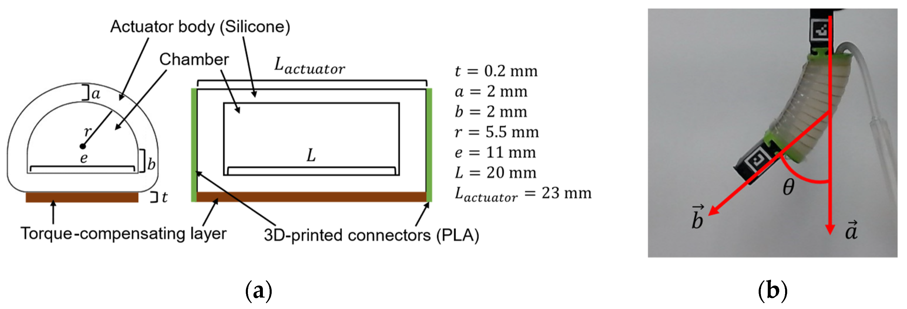
20]. Based on these considerations, the joint modular soft actuator can be considered a suitable soft actuator for use in a telerehabilitation environment because it provides high bending performance with minimal energy and can accommodate individual differences with minimal effort. However, it is necessary to incorporate an estimation of the stiffness of the finger joints (i.e., spasticity condition evaluation function), though stiffness estimation with joint modular soft actuators has not been studied yet. In this study, we designed a modular version of the SECA for actuating individual joints (Modular-SECA). However, as explained in the following paragraph, the analytical model of SECA for estimating finger joint stiffness is not completely applicable to this new type of actuator.
The analytical model of the SECA is derived from the air chamber unit energy conservation law, so the length of the air chamber is included in the analytical model, but not the length of the actuator itself. When the lengths of the air chambers are equal, the analytical model can be interpreted as indicating that the SECA and Modular-SECA have the same bending performance. Therefore, it is possible to estimate the stiffness of the Modular-SECA using the original analytical model of the SECA. However, unlike the SECA, the joint modular soft actuator has rigid connectors at both ends, and the length ratio of the actuator body to the chamber is different [17,20]. Therefore, the two types of soft actuators may exhibit different bending performances, and the analytical model of the SECA cannot be applied directly to that of the Modular-SECA.
Another problem of the stiffness estimation method described in [17] is caused by using a marker-based joint angle measurement. However, it is difficult for the patient or his/her family members to attach the markers at precise positions, which limits its application to telerehabilitation.
Furthermore, using 2D markers limits the acquisition of joint angles on a flat surface, making it impossible to measure the joint angles of the middle and ring fingers, and thus making it difficult to estimate the joint stiffness of them. Zhou et al. have developed a system that simultaneously obtains the joint angles of multiple fingers and estimates their stiffness by integrating a flex sensor into an actuator [22]. Flex sensors do not interfere with the bending response of soft actuators too much, but they must be calibrated individually for each actuator and cannot measure finger or hand orientation [23,24]. Moreover, using this system, it is not possible to measure joint angles when a soft actuator is not attached. By designing a system that can measure joint angles without having the soft actuators attached, it is also possible to measure joint range of motion, increasing the system’s functionality. In addition, having a high-cost system can limit how many devices can be provided for telerehabilitation [25].
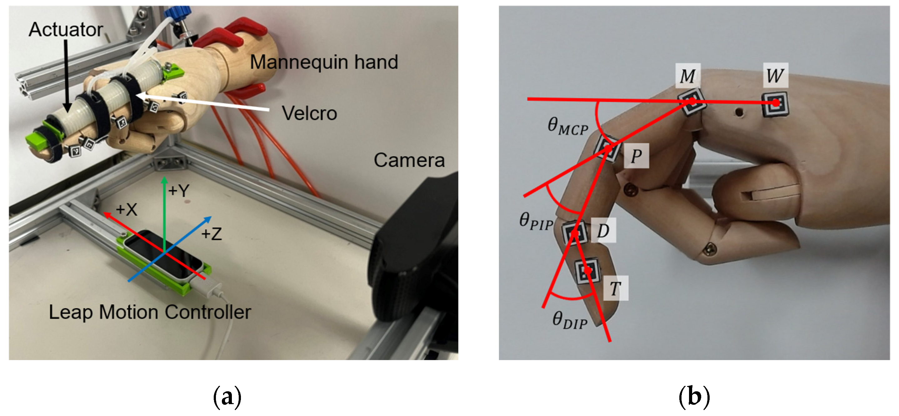
The leap motion controller (LMC) is an inexpensive and compact marker-less measurement device for tracking and acquiring the position of hand joints. Although the accuracy of hand joint angle measurement is not sufficient for rehabilitation purposes [26], it is possible to improve the measurement accuracy by fitting a regression model of joint angle [27]. However, the combined use of LMC and soft actuators has not yet been investigated. Especially, joint modular soft actuators may cause the motion of one single joint, which is different from most natural hand motions. It is also unclear how the attachment of the soft actuator affects the LMC and whether or not the measurement accuracy can be improved in the same way as when the soft actuator is not attached.
In this study, we proposed finger joint stiffness estimation for hand–finger joints using Modular-SECAs and the LMC, and verified the feasibility of this procedure by performing stiffness estimation on a mannequin hand and a subject’s MCP joint, respectively. We designed the Modular-SECA, a joint modular soft actuator incorporating the finger joint stiffness estimation function. In addition, correction terms (or parameters) were added to the previous analytical model for the bending analysis of a Modular-SECA supporting a joint for the purpose of hand rehabilitation. The correction parameters were determined by comparing the values of the bending angles obtained from the analytical model with measured angles from a free bending experiment with the Modular-SECAs. Moreover, a regression model accounting for the actuation for and motion of the neighboring joints was proposed to correct the direct outputs of LMC.
This paper is organized as follows: First, the design and improved analytical model of the joint modular soft actuator for stiffness estimation are presented. Next, the regression model method to improve the accuracy of LMC joint angle measurement is presented. Finally, validation experiments using a mannequin hand and a subject’s hand are presented in which stiffness estimation is performed using a combination of these methods.

2. Materials and Methods

2.1. Joint Modular Soft Actuators for Joint Stiffness Estimation

This subsection gives a concise introduction to the design of the joint modular soft actuator, for the sake of clarity. A more comprehensive explanation can be found in [20]. The analytical model for the SECA and thereby the improved analytical model for the joint modular soft actuator are explained.

2.1.1. Design and Fabrication

The Modular-SECA consists of an elastomer body, a semi-circular air chamber with air pockets, a silicone tube, a fiber reinforcement wrapped around its circumference, 3D-printed rigid connectors, and a torque compensation layer. When pressurized with air pressure, the fibers wrapped around the surface of the actuator suppress radial elongation. The torque-compensating layer limits axial elongation at the bottom, allowing only the top of the actuator to extend and the finger to bend. During decompression, the torque-compensating layer provides a supplementary bending moment to extend the finger to its initial position.
The silicon part of the actuator was made by pouring silicon (Smooth-On, Dragon Skin 10 Medium) into a 3D-printed mold. A stainless-steel plate (A2 stainless-steel plate) with a thickness of 0.2 mm was used for the torque compensating layer, which was attached to the bottom of the silicon part of the actuator. Next, 0.3556 mm diameter reinforcing fibers made of Kevlar® (Dupont, Inc., Wilmington, DE, USA) were wound around the actuator, and silicon tubing for air flow and 3D-printed connectors made of polylactic acid (PLA) resin were attached. Finally, a thin coat of silicone (Smooth-On, Dragon Skin 10 Medium) was applied over the fibers to prevent them from shifting. Figure 1a shows the cross-section and dimensions of the actuator.

2.1.2. Analytical Model for Energy Conservation of Modular-SECA

The analytical model for the free space bending analysis of the SECA is obtained via the conservation of energy as in [17]:
P = W A + W L V
where P , W A , W L and V denote the input air pressure, the bending strain energy stored in the soft actuator body, the bending strain energy stored in the torque-compensating layer, and the increase in volume, respectively. The bending analysis in free space is the bending analysis using the actuator only.
Due to the structural differences between the SECA and the Modular-SECA, the energy distribution in the actuator is different. The rigid connectors attached to the two ends of each actuator and the neighboring Modular-SECA connected through the connectors may cause the change in the ratio of both W A to W L , and their sum to P V . Therefore, the analytical model of the SECA was modified to match the energy distribution of the Modular-SECA, as shown in Equation (2):
P = α A W A + α L W L α V V
where α A , α L and α V are the correction parameters added to Equation (1).
The analytical model for bending analysis in free space was verified with a Modular-SECA prototype experiment, and a finite element model (FEM). In this study, the Yeoh 3rd-order model was chosen for the strain energy density function of silicone rubber as follows [28]:
w m = i = 1 3 C i λ 2 + λ 2 2 i
w m is the bending strain energy density function, λ is the principal stretch, and C i ( i = 1,2 , 3 ) is the material coefficient. The 3rd-order Yeoh model parameters for the silicon used (Smooth-On, Dragon Skin 10 Medium) were C 1 = 0.04773   M P a , C 2 = 3.42 × 10 4   M P a , and C 3 = 1.1942 × 10 6   M P a , respectively. These parameters were calculated by using the material data provided in [29]. The material parameters of the stainless-steel plates used as torque compensation layers with a Young’s modulus of 193 GPa, a Poisson’s ratio of 0.318, and a density of 8000 kg/m3 [30]. The bending angle in free space was measured by a camera-based two-dimensional marker detection system (Figure 1b). The camera (C930eR, Logicool, Lausanne, Switzerland) recorded the 2D position coordinates of the markers and the angle was calculated. The bending angle, θ , was obtained using Equation (4) when air pressure was applied from 0 kPa to 80 kPa in 10 kPa increments. The bending angles obtained from the experiment were compared with those from the analytical model, and correction parameters were identified using the least-squares method. A more comprehensive description of FEM can be found in Appendix A.
θ = c o s 1 a · b a b

2.2. Finger Joint Angle Measurement Using Leap Motion Controller

This subsection describes the performance of LMC and a regression model to correct joint angles determined using LMC.

2.2.1. Leap Motion Controller

Leap Motion Controller (Ultraleap, Bristol, UK) is a hand motion capture system that can recognize positions of hand joints within a maximum range of 60–80 cm from the top of the device with a 140 × 120-degree field of view [31]. LMC is a marker-less motion capture device that uses reflections from three infrared LEDs on either side of and between the two infrared cameras to estimate the position of the fingers. The device weighs 32 g and measures 30 mm × 11.30 mm × 80 mm [32]. LMC uses a proprietary algorithm to extract hand data from raw sensor data. These data consist of infrared brightness values and calibration data to remove distortions [25].

2.2.2. Joint Angle Measurement

In this study, a mannequin hand was used instead of a human hand. The mannequin hand is easy to modify, and it can keep gestures without involuntary motions, making it suitable for experiments in which the same measurement is repeated. Joint angles were measured using two methods: LMC and a camera-based 2D marker detection system. The values from the 2D marker detection system were similar to those measured using a goniometer (Appendix B), so these values were used as the reference values of joint angles in this study. Figure 2a shows the setup for the joint angle measurement. For the ease of 2D marker attachment, the index finger of the right hand was used for the measurement. The 2D markers were attached to the side of the index finger of the mannequin hand, and the distance between LMC and the mannequin hand was set at 15 cm [33]. The frictional resistance of each joint of the index finger of the mannequin hand was negligible.
The 2D marker detection system provides the two-dimensional position coordinates of the marker’s center, while LMC provides the three-dimensional position coordinates of the finger joints. Thus, the position coordinates of points W to T shown in Figure 2b were obtained, and the angles of the distal interphalangeal (DIP) joint, proximal interphalangeal (PIP) joint, and MCP joint were calculated using the following set of equations [26]:
θ M C P = cos 1 W M · M P W M · M P
θ P I P = cos 1 M P · P D M P · P D
θ D I P = cos 1 P D · D T P D · D T
The angle obtained via the method using the two-dimensional marker is denoted as 2D Angle, and the angle obtained by the method using LMC is denoted as the LMC Angle.

2.2.3. Joint Angle Correction Model

Ganguly et al. conducted a comparative experiment using LMC and a gold-standard marker-based motion capture system, to measure joint angles during finger flexion and extension movements [26]. The results showed that LMC could not replace the gold-standard system regarding angle measurement. Therefore, the output angles need to be corrected to estimate finger joint stiffness using LMC. Li et al. derived a regression model for each index finger joint to improve the accuracy of joint angle measurement [27]. Although there was a certain amount of error after joint angle correction, the overall error was improved to within 10 degrees.
In this study, a regression model is generated for taking into consideration the influence of joint modular soft actuators to multiple joints of fingers. Therefore, unlike the previous study, the regression model in this study needs the following explanatory variables.
  • Angles of other joints:
    As shown in Appendix C, the LMC Angle of one joint is affected by the interaction between joints of the same finger. Therefore, to estimate the angle of one joint, it is necessary to provide its current LMC Angle value, but also the angle values of other joints in the same finger.
  • Dummy variables indicating whether one joint modular soft actuator is pressurized or not:
    When joint modular soft actuators are attached to the joints of one finger, the tendency of angle change of each joint differs depending on whether each soft actuator is pressurized or not (Appendix C). Therefore, if a regression model is generated from all the data regarding the angular changes of all joints in (a)–(g) in Figure A2, corresponding to all combinations of the Boolean pressurization (1 = pressurized, 0 = not pressurized) variables, p D I P , p P I P and p M C P , except the case where p D I P = 0, p P I P = 0, and p M C P = 0, the goodness of fit is likely low. Therefore, by introducing the Boolean pressurization variables, a single model can be fitted to reflect the different angular change tendencies caused by different pressurization combinations.
  • Terms reflecting the interaction between variables:
    Since it is impossible to guarantee that there is no interaction between all the explanatory variables, adding interaction terms may improve the correction performance.
Based on the above points, the regression models were generated to correct the LMC Angles of the three joints, respectively, using the measurement data in Appendix C. LMC Angles of the three joints of the same finger ( D I P , P I P , and M C P ) and the dummy pressurization variables were used as explanatory variables ( p D I P , p P I P , and p M C P ) and their interaction terms were also added as explanatory variables (Table 1).
However, explanatory variables that do not contribute to the correction of joint angles may be included. The exclusion of variables with low contribution would improve the correction of joint angles. Therefore, a variable selection was performed to the 23 candidate explanatory variables shown in Table 1 to obtain the final explanatory variables.

2.2.4. Variable Selection

In order to effectively select the explanatory variables closely associated with the target variable, the forward–backward stepwise selection, one of the most used stepwise selections, was used. The forward–backward stepwise selection was created based on [34]. The procedure is described below.
  • Initial variable selection:
    Among the given candidate explanatory variables, the variable with the largest single correlation coefficient with the target variable and whose regression contribution rate (regression variance divided by residual variance) is larger than the predetermined constant F I N is the initial variable.
  • Adding a variable:
    By creating a regression model with the current explanatory variables and adding a new variable from the candidate variables, the variable is included as an explanatory variable if it has the largest increase in the contribution rate and the increase in contribution rate is larger than or equal to F I N .
  • Removing a variable:
    A regression model is created with the current explanatory variables, t 2 is determined to test the significance of each partial regression coefficient, and the relevant variable is removed if its minimum is smaller than the predetermined constant F O U T .
  • End of variable selection:
    Steps 2 and 3 are repeated in the same manner, and the calculation is terminated when there are no more variables to be removed because they are smaller than F O U T or added because they are larger than F I N .
When applying this method, the addition/removal criteria for variables depend on the values of F I N and F O U T , so how to determine these values is very important. In Ref. [34], F I N = F O U T = 2.0 is considered appropriate, and this value is also used in this study.

2.3. Finger Joint Stiffness Estimation

This subsection describes how the performance of the proposed stiffness estimation method is verified.

2.3.1. Analytical Model for Joint Stiffness Estimation

Since stroke patients experience strong resistance to extension due to excessive tension in the finger flexors, only the joint stiffness upon extending the fingers was targeted in this study [17]. Using the correction parameters identified in the previous section and [17], the analytical model for the finger joint stiffness estimation using the Modular-SECA is as follows:
k = 2 α A W A + α L W L α V P V θ θ 0 2 , θ 0 , 0.7 θ 0
k , θ and θ 0 are the joint stiffness, the joint angle, and the resting angle, respectively. In this study, the range of possible joint angles was set to θ 0 , 0.7 θ 0 as in the method using the SECA because we wanted to estimate the stiffness of the joint when it was extended from its resting angle.

2.3.2. Joint Stiffness Estimation Experiment

Two MCP stiffness estimation experiments were conducted. First, stiff joints were made for the mannequin hand using torsion springs, and the stiffness estimated using the proposed methods was compared with the spring constant to decide the estimation accuracy. Next, the feasibility of the proposed method for joints of multiple fingers was verified by estimating the stiffness of a subject’s MCP joints.
In the stiffness estimation experiment, the angles of MCP were measured when air pressure was applied from 0 kPa to 80 kPa at 10 kPa intervals. After the measurements, the stiffness values for each pressure were obtained using Equation (8) in the range θ 0 , 0.7 θ 0 . Finally, these stiffness values were averaged to obtain the final estimated stiffness value. The resting angle, θ 0 , was measured using the 2D marker detection system or a goniometer.

Joint Stiffness Estimation Using Mannequin Hand

Experiments using a mannequin hand require a target stiffness value for estimation. The modified Ashworth scale (MAS), an assessment used in rehabilitation, is shown in Table 2. Based on the MAS scores of healthy subjects and stroke patients and the measured joint stiffness values [17,18,35], the relationship of the patient’s joint condition to the MAS score and the corresponding reference stiffness values were defined in two levels (low and medium) (Table 3). The torsion spring (SAMINI CO., LTD., Shizuoka, Japan) with a spring constant equivalent to the stiffness value of MCP of the index finger of the mannequin hand (Figure 3) was used.
Stiffness values were estimated using different combinations of analytical models (the SECA model and Modular-SECA model) and joint angles (2D Angle, original LMC Angle, and corrected LMC Angle), comprising six combinations overall.

Estimation of Stiffness of Joints of Multiple Fingers

The feasibility of estimating the stiffness of joints of multiple fingers using the proposed method was verified; two different states of joint stiffness were setup for this purpose: healthy and simulated-stiff.
The stiffnesses of MCP in multiple fingers (index, middle, ring, and little fingers) of a healthy subject’s right hand were estimated using the proposed method (Figure 4a). Simulated-stiffness joints with a higher apparent stiffness value were prepared by bandaging the healthy joints (Figure 4b). Each of the four fingers was bandaged to increase stiffness in the extension direction. For each state of stiffness, estimation was performed three times. The resting angle, θ 0 , was measured using a goniometer. The thumb was fixed with a fixture because thumb movement could have affected the measurement data, and the distance between the hand and LMC was set to 15 cm.
It should be noted that, in the experiment, when estimating the MCP stiffness of the index finger, both the original LMC Angle and corrected LMC Angle were used, though for the middle, ring, and little fingers, their MCP stiffness values were estimated using only the original LMC Angle. This is because that, the regression model for the corrected LMC Angle of the index finger could be built by using the reference angle values obtained from the 2D marker measurement system; however, due to the difficulty to attach 2D markers to the other fingers, it was difficult to derive an angle correction model for them.
Certainly, one option might be making use of the angle correction model of the index finger for the other fingers. Actually, as shown in Appendix D, for the middle and ring fingers, the PIP and MCP joints had a good fit (>0.7) with the corrected LMC Angle from the index finger, but the DIP joint had a poor fit. Nevertheless, the angle correction model for the MCP joint of the index finger also includes the DIP angle as an explanatory variable; thus, the angle correction model for the index finger cannot be used for the other fingers.

3. Results

3.1. Analytical Model of the Modular-SECA

The correction parameters identified were α A = 1 , α L = 0.5 , and α V = 1.15 . Substituting these parameters into Equation (2), the analytical model for the Modular-SECA is as follows:
P = W A + 0.5 W L 1.15 V
Compared to the SECA analytical model, the coefficient of the increase in chamber volume relative to the air pressure input increased, and that of the bending strain energy stored in the torque compensation layer decreased in the actuator’s energy distribution. Figure 5 shows a graph comparing the actuator-only bending angles in free space. No difference is seen between the results of the analytical model, experiment, and FEM simulation for the Modula-SECA. However, there is a difference between the results of the SECA analytical model and those of the Modular-SECA.

3.2. Joint Angle Correction Model with Actuator

Regression models created for each of the DIP, PIP, and MCP joints to correct the joint angles with soft actuators were as follows:
D I P = 6.77 D + 13.71 P 12.27 M + 92.36 p D + 65.56 p P 40 p M 0.01 P · M    78.93 p D · p P 53.97 p P · p M 69.07 p D · p M + 69.86 p D · p P · p M    + 6.9 D · p M + P · 4.66 p D 0.56 p P 15.74 p M M · 4.79 p D 16.41 p M
P I P = 2.55 D + 1.69 M 3.32 p P 0.04 D · P 0.08 D · M 0.001 D · P · M      1.6 p D · p P + 4.54 p D · p M + 4.49 p D · p P · p M      + D · 1.49 p P 1.2 p M M · 0.25 p D + 0.29 p M
M C P = 1.04 D + 0.62 M + 12.01 p P 0.88 p M 0.01 D · P      + 1.35 p D · p P 0.67 p D · p M 3.04 p P · p M 1.27 p D · p P · p M      D · 1.1 p P 0.92 p M P · 0.12 p D 0.8 p P M · 1.07 p P 0.42 p M
D I P D , P I P ( P ) and M C P ( M ) are LMC Angles, and p D I P p D , p P I P ( p P ) and p M C P ( p M ) are dummy Boolean variables indicating whether the soft actuator corresponding to each joint was pressurized or not. The adjusted coefficients of determination were 0.895 for the DIP joint, 0.992 for the PIP joint, and 0.995 for the MCP joint. The PIP and MCP joints were above 0.9, and the DIP joint was slightly below 0.9. The model consisted of around 15 variables, resulting from the variable selection process. As shown, the models for each joint contain the LMC Angle of other joints.

3.3. Joint Stiffness Estimation Using Mannequin Hand

3.3.1. Regression Model Joint Angle Correction Performance

The 2D angle, original LMC Angle, and corrected LMC Angle (from the proposed model) of the three joints (DIP, PIP, and MCP) under each pressure from 0 kPa to 80 kPa during the stiffness estimation are shown in Figure 6. To compare the difference in correction performance between the proposed regression model and the regression model derived from the method of the previous study [27], third-order regression models were generated using only the angle of the target joint to be corrected as the explanatory variable (Equations (13)–(15)). The corrected LMC Angle (from the previous study) is also shown in Figure 6.
D I P = 0.006 D I P 3 0.32 D I P 2 + 5.95 D I P 24.96
P I P = 0.0002 P I P 3 0.02 P I P 2 + 1.37 P I P + 13.95
M C P = 0.002 M C P 3 0.16 M C P 2 + 5.22 M C P 22.71
The correction performance of each regression model was evaluated in terms of the root-mean-square error (RMSE) values between the 2D Angle and LMC Angle in Figure 6 (Table 4). As shown, except the DIP measurement on the middle stiffness level (double underlined in Table 4), the corrected LMC Angle under the proposed model improved the prediction accuracy compared to the corrected LMC Angle from the previous study. The model in the previous study did not include soft actuator pressure information as an explanatory variable, so the model had to be changed when the combination of joints to be pressured changed. On the other hand, compared with original LMC Angle, the proposed model showed improvement, except for the two measurements underlined in Table 4.

3.3.2. Joint Stiffness Estimation Accuracy

The results of the estimated MCP joint stiffness of the index finger of the mannequin hand are shown in Table 5. Comparing Method 1 (the SECA model with 2D Angle measurement) and Method 2 (the Modular-SECA model with 2D Angle measurement), it is clear that the corrections to the analytical model improved the accuracy of the stiffness estimation. Comparing Method 3 (the SECA model with the original LMC Angle measurement) and Method 5 (the SECA model with the corrected LMC Angle measurement), and Method 4 (the Modular-SECA Model with the original LMC Angle measurement) and 6 (the Modular-SECA model with the corrected LMC Angle measurement), it seems obvious that the correction of the LMC Angle improves the accuracy of the stiffness estimation. However, the comparisons between Methods 3 and 4, and Methods 5 and 6 disclose that the accuracy of stiffness estimation deteriorated when the LMC Angle was used due to the correction of the analytical model. Figure 7 shows the change in the stiffness value estimated by the joint angle at a 40 kPa input air pressure in the low stiffness experiment. Even though the accuracy of the analytical model for the Modular-SECA is better than that of the SECA model for the reference value of the joint angle (2D Angle), a deviation of the joint angle estimation produces better performance for the analytical model of the SECA model instead of Modular-SECA, which deviates from our expectation. Therefore, despite the improvement made in both the analytic model and LMC Angle measurement, both of them need further enhancement.

3.4. Multiple Finger Joint Stiffness Estimation

First, Table 6 shows that the joint angle during rest was larger in the healthy joint. On the other hand, the joint angle when the soft actuator was attached and not pneumatically pressurized showed a flexion angle, while the original LMC Angle showed an extension angle. Figure A3 shows that when the LMC Angle showed an extension angle in the MCP joint, the smaller the flexion angle measured with the goniometer was, the larger the LMC Angle extension angle was. Therefore, the flexion angle at 0 kPa was larger for the stiff joint. In other words, the stiff joint had stronger resistance in the extension direction, and the amount of angle change caused by the soft actuator was smaller. Therefore, the stiffness value of the stiff joint was higher than that of the healthy joint, and bandaging was an appropriate method to increase the apparent stiffness value.
The mean and standard deviation of three measurements of the stiffness values estimated for the MCP joints of the fingers are shown in Table 7.
For the little finger, the stiffness estimates for stiff joints were higher than those for healthy joints. Though, for the ring finger, it was difficult to distinguish between healthy and stiff joints from the estimates. For the MCP joint of the index finger and middle finger, this was even reversed.
Another issue is that of negative estimates of stiffness. As can be seen in Figure 7, the accuracy of the joint angles was low because the estimated values were negative depending on the joint angle. The angle correction model for the index finger was generated using joint angle data obtained from a mannequin hand. Its applicability to the human hand was low, and the lack of LMC Angle correction may have resulted in negative values.
Moreover, because the fingers were separately restrained by bandaging (Figure 4b), the strength of the restraint was different for each finger, causing a large difference in the apparent stiffness for each finger. These issues revealed that stiffness estimation for a human finger is not so reliable, though the possibility for simultaneous joints of multiple fingers was shown.

4. Discussion

The results show that the SECA and Modular-SECA have different bending performances, and the interaction of joints affected the output of LMC when the Modular-SECA was attached. Furthermore, it was confirmed that the accuracy of the stiffness estimation with the Modular-SECA could be improved by correcting the analytical model of stiffness estimation and the joint angles.

4.1. Analytical Model of Modular-SECA

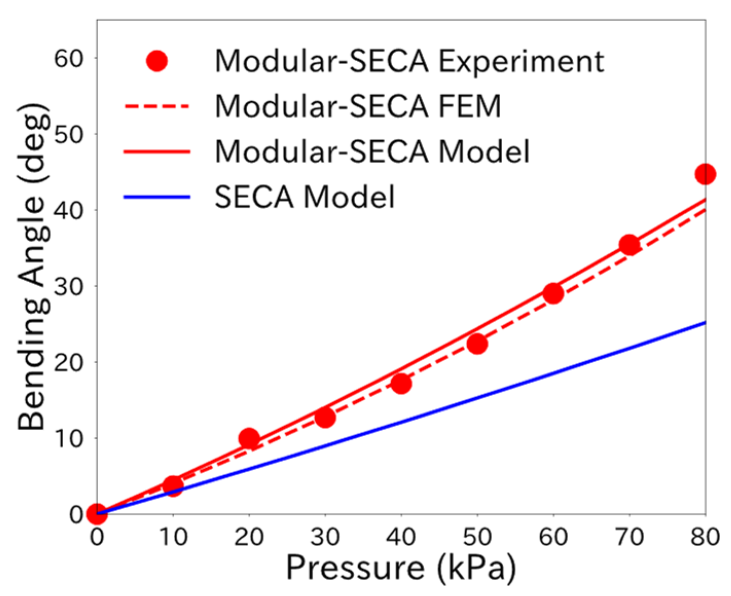
The free space bending analysis results suggest a difference in the energy distribution in the actuator between the Modular-SECA and SECA. It was confirmed that the chamber volume increase, V , relative to the air pressure input was larger for the Modular-SECA than that for the SECA. The bending strain energy, W L , stored in the torque compensation layer was smaller for the Modular-SECA. This may have been due to the rigid connectors attached to both ends of the Modular-SECA, which reduced the energy allocated to W L within the energy conservation law. In previous studies, W L was modeled as a cantilever beam subjected to a pure bending moment [17]. However, the Modular-SECA is considered to be subjected to an additional bending moment in the torque compensation layer. Therefore, at the same air pressure input, the energy required to bend the torque compensating layer is reduced, and the volume increase in the chamber is considered to have increased.
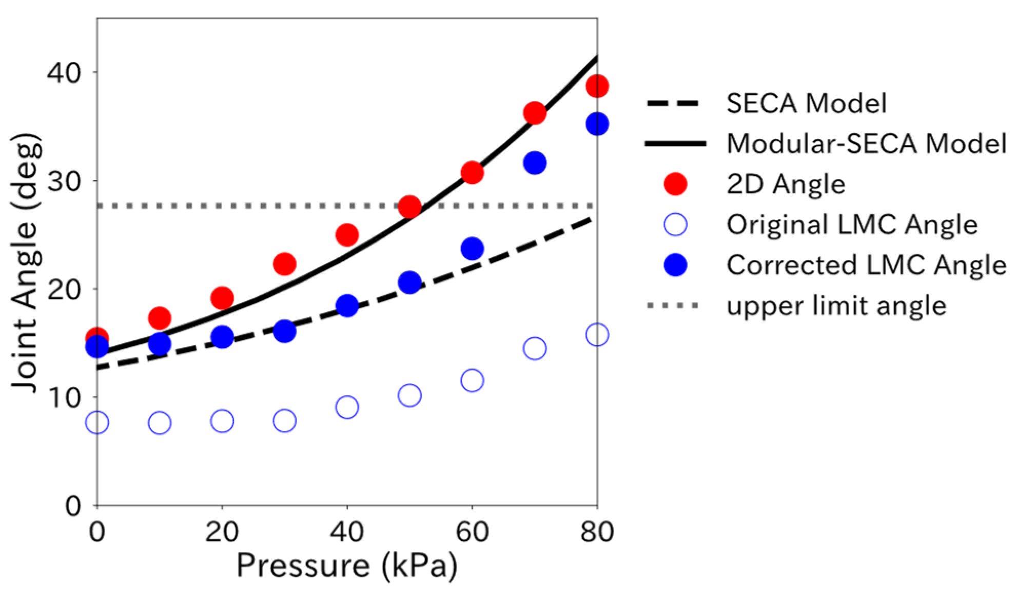
From Figure 8, the difference between the 2D Angle and the bending angle obtained from the Modular-SECA analytical model is smaller than that in the SECA analytical model results. However, the estimated values for Method 2 (Modular-SECA Model with 2D Angle measurement) in Table 5 did not reach the target values. This may be due to the lack of correction in the Modular-SECA analytical model. In particular, the difference between the experimental and Modular-SECA model bending angles at 0 kPa suggests that the correction may be insufficient. This difference is thought to have persisted afterward, preventing the estimation results of Method 2 from reaching the target values. A feature of the SECA is that the torque compensation layer provides a supplementary bending moment to return the finger to its initial position under reduced pressure. 
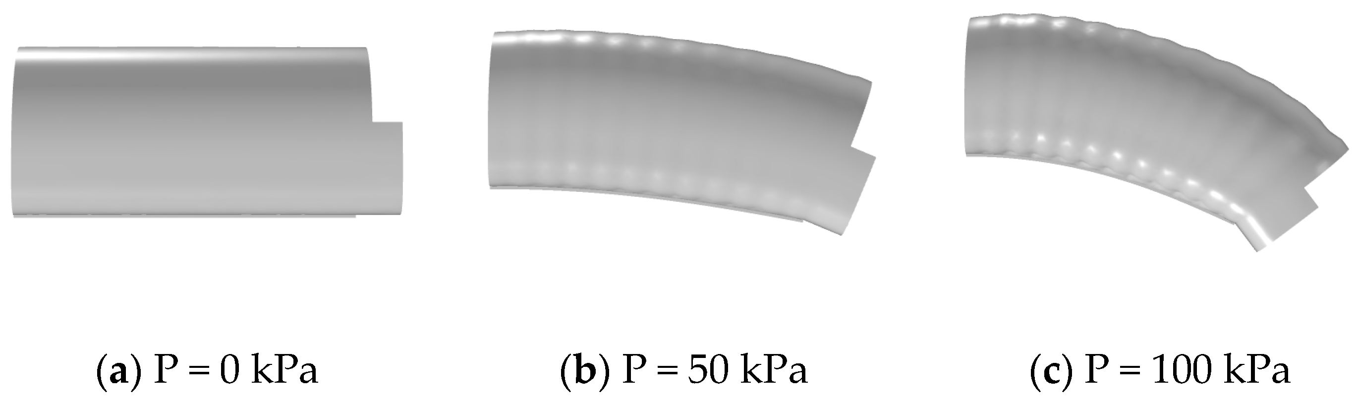
Figure 5 shows that the bending angle of Modular-SECA is larger than that of the SECA under applied pressure and that the force in the bending direction is greater. However, under reduced pressure, the auxiliary bending moment provided by the torque-compensating layer of the Modular-SECA is smaller than that of the SECA, and the force in the extension direction may be smaller. θ θ 0 2 in Equation (8) is a term that expresses the effect of the bending moment of the torque compensation layer on the bending angle. If the bending moment provided by the torque-compensation layer of the Modular-SECA is small, a correction parameter may also need to be provided for this term.

4.2. Finger Joint Angle Measurement Using Leap Motion Controller

First, Appendix E shows that the LMC Angle change trend changes with the attachment of the soft actuator. In Figure A2a,d, the trend of the LMC Angle change around 80 kPa is altered compared to that at the previous pressure point. Briefly, 80 kPa is when the mannequin hand’s index finger is bent to the point where the soft actuator is visible from LMC’s camera. Therefore, LMC recognized the soft actuator as a part of the finger, and the output angle changed.
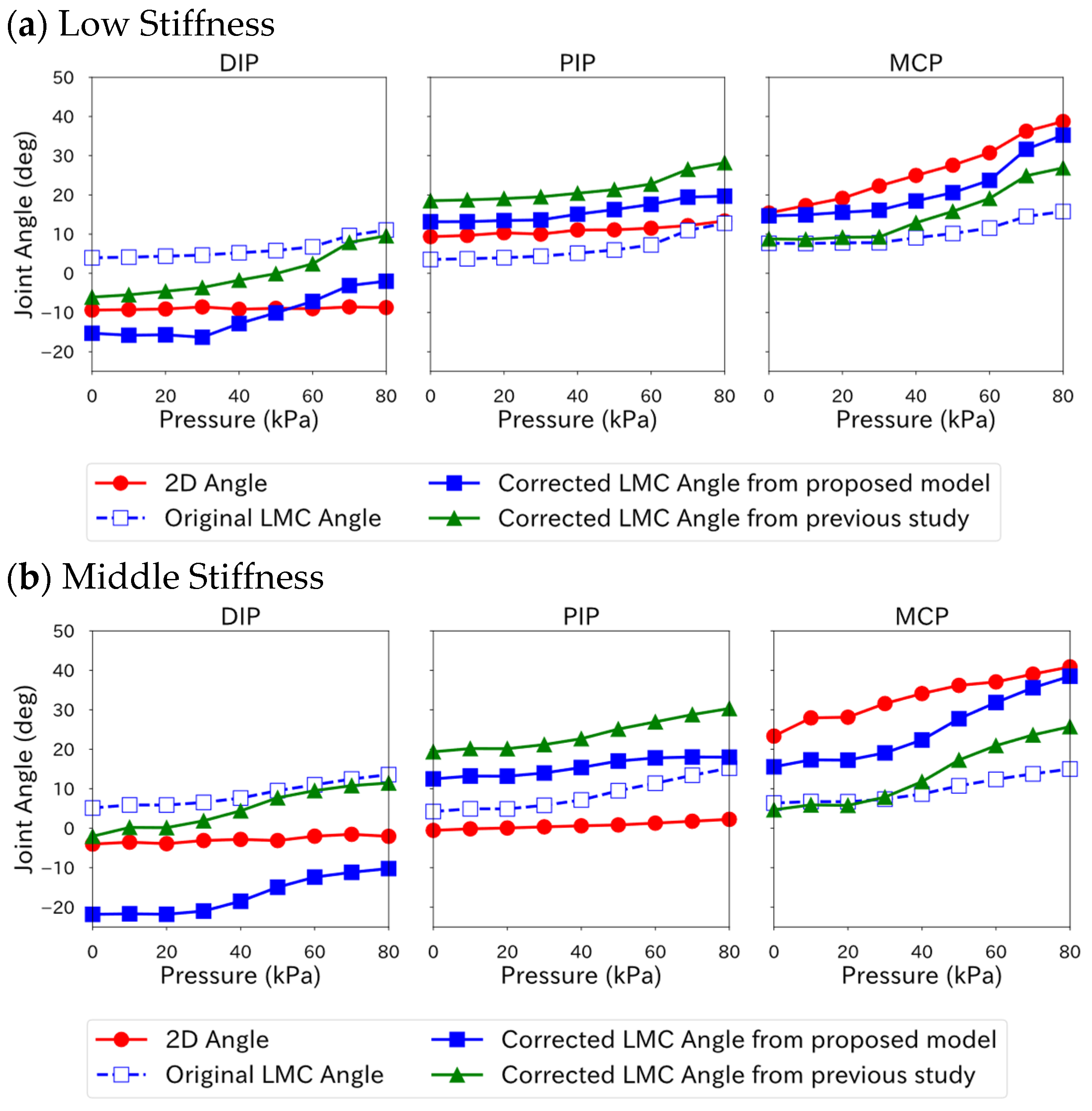
When the soft actuator was applied, the angle correction model included the angle of other joints, suggesting that LMC Angle is affected by the interaction between joints within the same finger. 
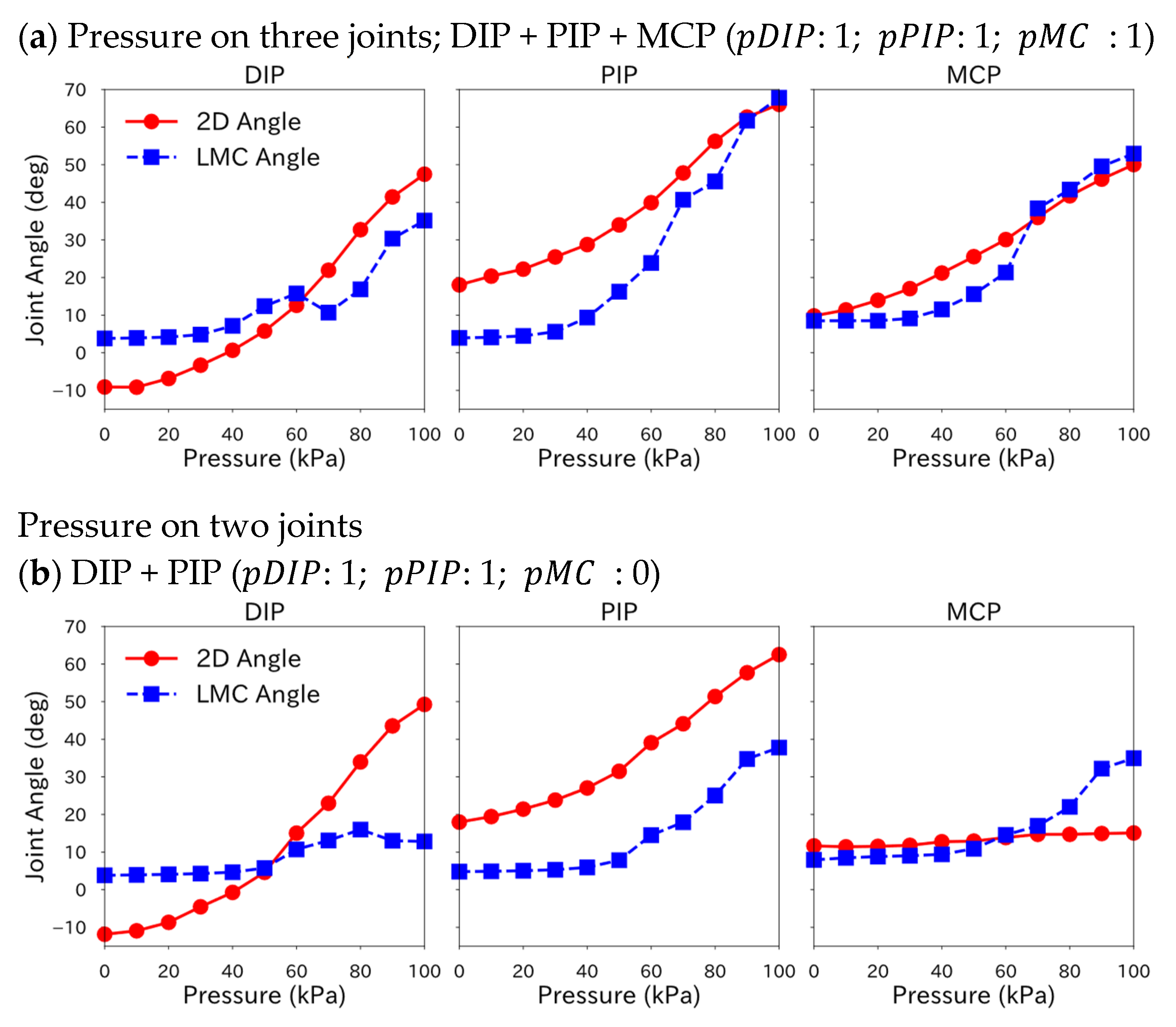
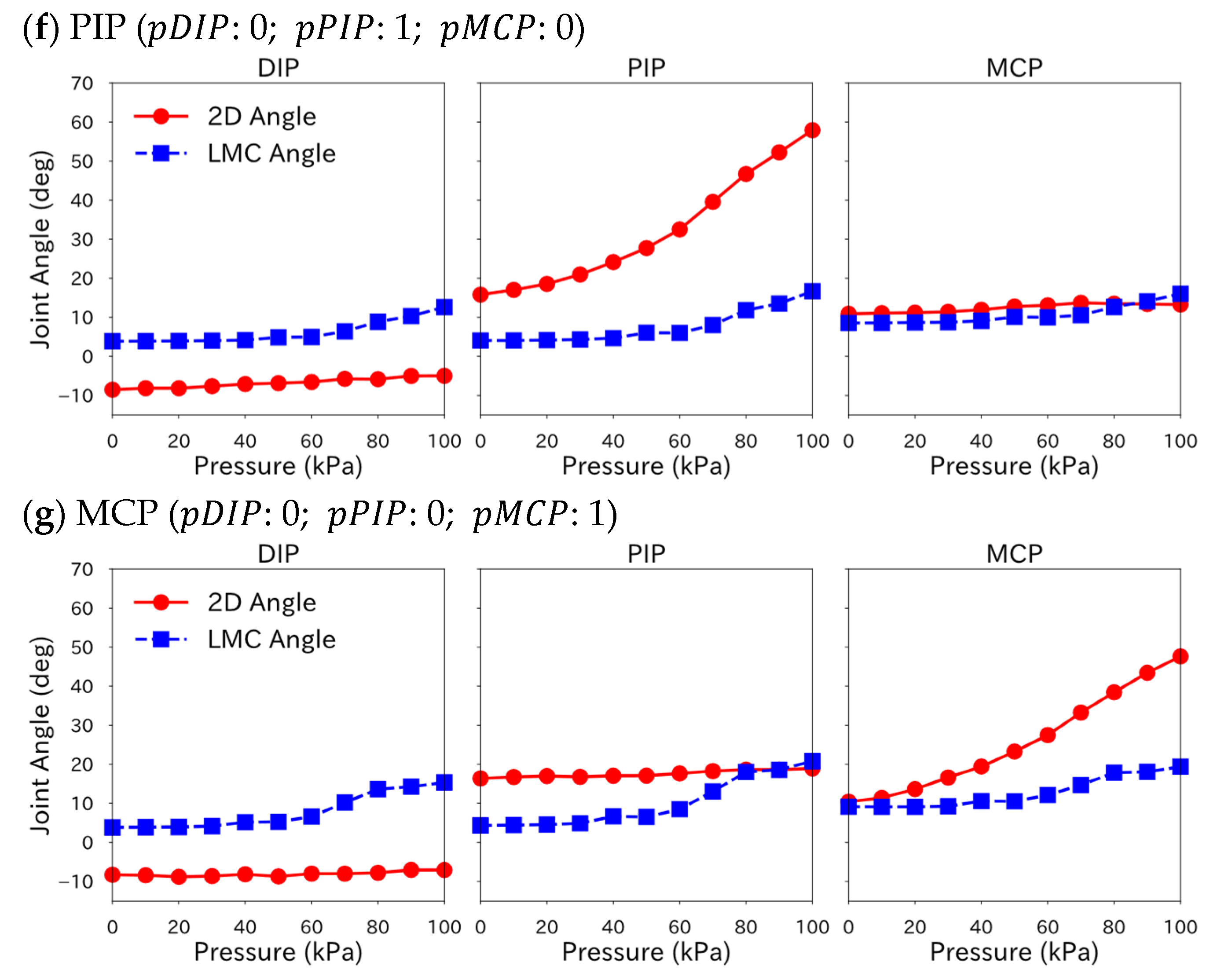
Table 4 shows that the correction performance of the angle correction model is high for joints with large angle changes when the soft actuator is pressurized. However, it may be low for joints that are not pressurized and have small angle changes. This may be due to biased training data for the joints where the soft actuators are not pressurized, resulting in lower model prediction accuracy. It also suggests that including the angles of other joints in the explanatory variables may lead to an increase in correction accuracy but may also lead to a decrease. Correction performance varies with stiffness level in Table 4 because correction accuracy varied with the angles of other joints. Although the model of the previous study can improve correction performance by increasing the order of the regression model, it requires separate models for each combination of joints to which the soft actuator applies pressure.
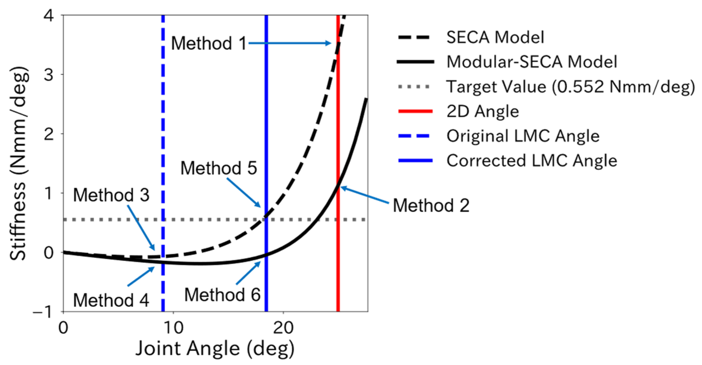
Figure 6 and Figure 8 show that the upper limit of the stiffness estimation range using the LMC Angle is wider than that using the 2D Angle because the LMC Angle is output smaller than the 2D Angle even after correction. In Figure 8, the stiffness estimation range for 2D Angle is 0 kPa to 50 kPa, while corrected LMC Angle is 0 kPa to 60 kPa; the stiffness estimation using the LMC Angle includes a greater stiffness value at each pressure in the final estimate stiffness value than that using the 2D Angle. Therefore, to improve the estimation performance, it is considered effective not only to improve the correction accuracy of the LMC Angle but also to change the stiffness estimation range.
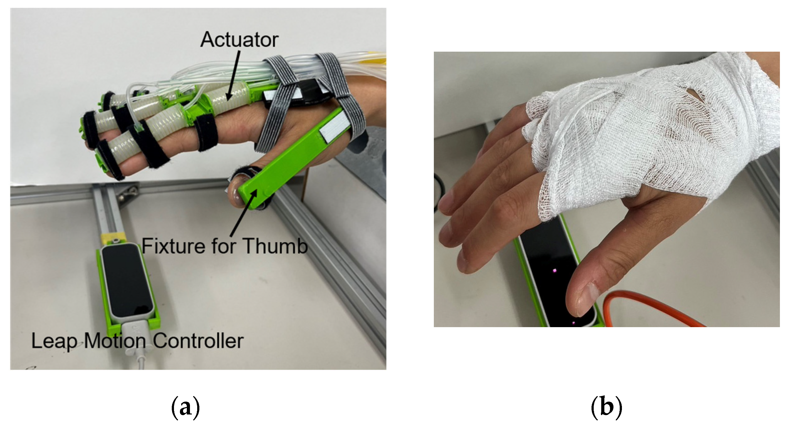
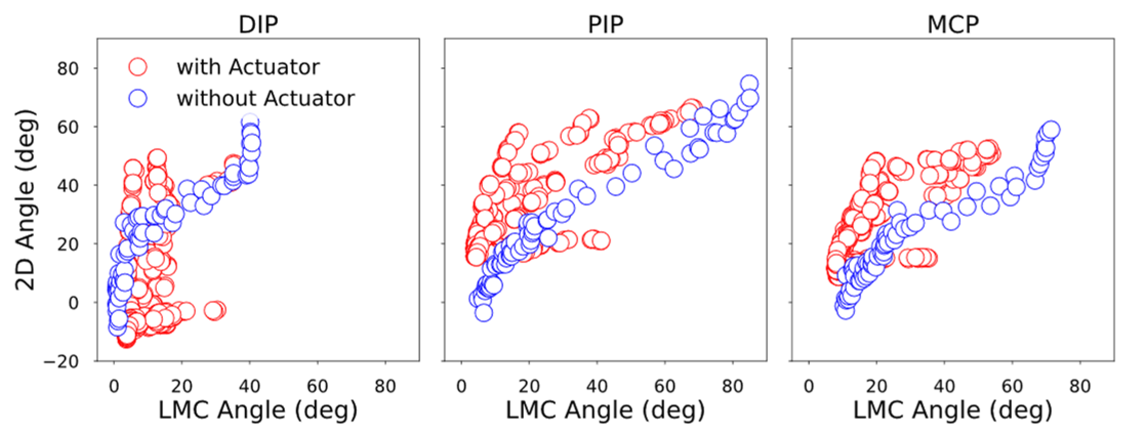
When the Modular-SECA was attached to a human hand, MCP joints were constantly flexed during the experiment, while the LMC Angle showed an extension angle. Since none of the LMC Angle of the MCPs showed an extension angle in the data when the regression model was created, the correction performance of the regression model at the extension angle was insufficient, leading to the under-correction of the LMC Angle.
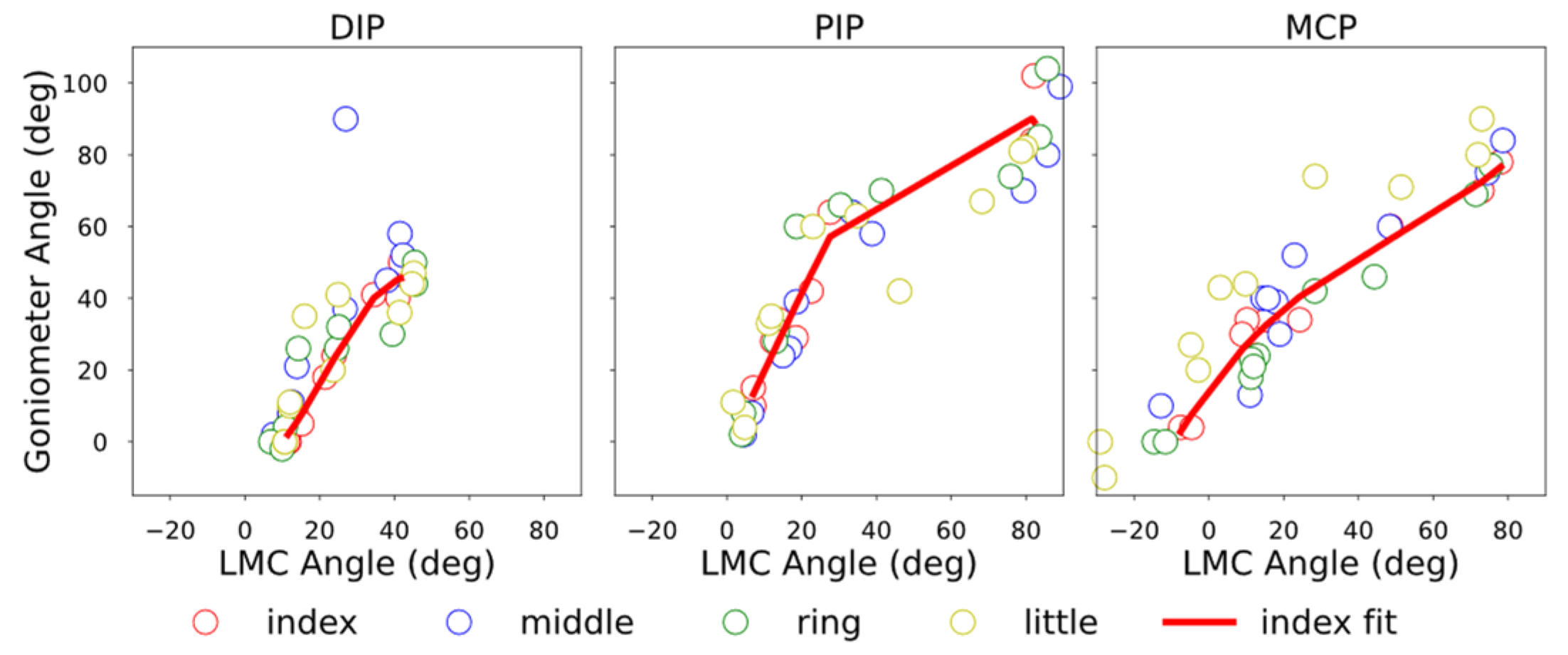
Since the angle correction model for the index finger could not be applied to the middle and ring fingers, it is necessary to derive an angle correction model for each finger separately. However, since it is difficult to measure joint angles using 2D markers for the middle and ring fingers, it is not possible to derive an angle correction model using the same method as in this study. Therefore, it is thought that the angle correction model for the index finger can be applied by excluding from the candidate explanatory variables for the regression model for the index finger those variables that include the angle of the DIP joint, which has a low degree of fit with that of the index finger.

4.3. Proposed Method for Finger Joint Stiffness Estimation

The stiffness estimation using LMC and the Modular-SECA showed that the correction of the analytical model and joint angle improves the stiffness estimation results. However, the current estimation performance of the proposed method is insufficient due to the lack of both corrections, and the correction method needs to be improved. The final stiffness estimate is the average for each pressure in the stiffness estimation range, but variations exist among the estimates for each pressure. Therefore, the performance of the proposed method may be improved by weighting the more reliable estimates in the stiffness estimation range.

4.4. Contribution and Limitations

By using joint modular soft actuators, high bending performance can be achieved with minimal energy for telerehabilitation, and individual differences such as different finger sizes and different joint stiffness values can be accommodated with minimal effort.
Our contribution includes the following:
  • To the best of our knowledge, for the first time, finger joint stiffness estimation for using joint modular soft actuators was proposed and implemented. The accuracy of stiffness estimation needs further improvement, though the possibility has been shown and the direction for improvement has been made clear. In addition, the proposed stiffness estimation method enables the simultaneous measurement of multiple fingers, although the analytical model and the correction method for joint angles need to be improved.
  • The analytic model was updated from a previous model for the SECA, a whole-finger soft actuator, with additional parameters for accounting for the features of the joint modular soft actuator. The model could be regressed from experimental data and give a better prediction of the behavior of the joint modular actuators.
  • Leap Motion Controller was used for the first time for the angle measurement of joints of fingers supported by the joint modular soft actuators. A regression model was proposed to correct measurement results, taking into consideration multiple joint interaction intensified by wearing the soft actuators, and the influence of the actuation of the joint modular soft actuators. The effectiveness of the correction was validated by the experiment results. LMC can be used to measure the angles of finger joints not only when soft actuators are attached, regardless of whether they are actuated or not, but also when soft actuators are not attached.
On the other hand, there are several methodological and implementational limitations:
  • The high stiffness of joint cannot be estimated with the Modular-SECA. The reference value for high stiffness (a MAS (modified Ashworth scale) score of about 3) is 9.60 N mm/deg. Because the extension of the highly stiff finger caused by wearing the Modular-SECA was small compared with that of the SECA, the joint angle, θ , was not within the stiffness estimation range, θ [ 0 , 0.7 θ 0 ) . To estimate high stiffness as well, it is necessary to design a joint modular actuator that can extend the finger sufficiently with its intrinsic stiffness, or add another component to actively extend the joint extension.
  • Only the stiffness estimation of MCP joints of multiple fingers was tested. The stiffness estimation of DIP and PIP joints of multiple fingers needs to be tested in future.
  • The regression model used to correct the LMC Angle generated using data acquired from mannequin hands did not apply to human hands. Although mannequin hands are effective for multiple measurements due to their low data variability, they are unsuitable for model generation because they do not reproduce human finger movements such as intra-finger constraint. Therefore, if an angle correction model is generated using data acquired from a human hand, it may apply to both mannequin hands and human hands. Moreover, this may allow the generated regression model to be adaptable to the individual difference of hand dimensions.
  • The manually controlled input air pressure affected the human hand’s stiffness estimation. The speed at which the joint moves, which is affected by the input air pressure, is a factor that influences joint stiffness [37,38]. In the case of manual control, the rotational speed of the joints differed from measurement to measurement, which may have increased the variation in data. Thus, automatic pneumatic input control is necessary to realize the proposed method.
  • In this study, we did not test stiffness estimation in a telerehabilitation setting. In the near future, it is necessary to verify the effectiveness of the proposed method in such a setting.

5. Conclusions

In this study, we proposed a method combining the Modular-SECA and LMC for the stiffness estimation of finger joints in a telerehabilitation environment. The SECA analytical model for stiffness estimation was modified to be applied to the Modular-SECA, and the LMC Angle was improved by the regression models to improve the accuracy of the proposed method. It was also shown that using the angle information of other joints and the dummy variables indicating whether or not the soft actuator is pressurized is effective for the correction model of the LMC Angle with the soft actuator. Furthermore, the results suggest that the proposed method could be used in a telerehabilitation environment to evaluate the spasticity condition in case a more precise correction of the analytical model and the LMC Angle becomes available. Since the simultaneous estimation of multiple fingers’ MCP joints is feasible using the proposed method in this study, it is necessary to make it possible to estimate DIP and PIP joints and joints with high stiffness values. Moreover, in the near future, it is necessary to verify the effectiveness of the proposed method in a telerehabilitation setting.

Author Contributions

Conceptualization, F.M. and W.Y.; methodology, F.M., S.K. and P.E.T.V.; software, F.M.; validation, F.M. and P.E.T.V.; investigation, F.M.; data curation, F.M.; writing—original draft preparation, F.M.; writing—review and editing, S.K., P.E.T.V., M.-T.K., Y.-H.H., S.Y.H., J.G.-T. and W.Y.; supervision, W.Y. All authors have read and agreed to the published version of the manuscript.

Funding

This work was supported by Grant-in-Aid for Scientific Research (B), JSPS KAKENHI Grant Number 22H03450.

Acknowledgments

The authors would like to thank Zhongchao Zhou, Yuxi Lu and Ema Oba for their support in the experiments.

Conflicts of Interest

The authors declare no conflict of interest.

Abbreviations

LMCLeap Motion Controller
DIPDistal interphalangeal (joint)
PIPProximal interphalangeal (joint)
MCPMetacarpophalangeal (joint)
2D AngleJoint angle calculated using the two-dimensional marker
LMC AngleJoint angle calculated using LMC
WMidpoint of the wrist joint
MMidpoint of the MCP joint
PMidpoint of the PIP joint
DMidpoint of the DIP joint
TTip of the finger
SECAsoft-elastic composite actuator
Modular-SECAJoint modular soft-elastic composite actuator

Appendix A

The finite element model (FEM) of the Modular-SECA was built on COMSOL Mul-tiphysics 5.6®. Dragon skin 10 was modeled as a Yeoh third-order hyperelastic material. The Kevlar fibers, stainless-steel plate and PLA were all modeled as linear elastic materials. The material parameters used for Dragon Skin 10 and the stainless-steel plate were the same as those in Section 2.1.2. The Kevlar fibers were modeled with a Young’s modulus (E-31670 MPa), Poisson’s ratio (v-0.36) and density ( ρ -1440 kg/m3) [39]. For the PLA the material parameters used were E-4.4 GPa, v-0.3 and ρ -1240 kg/m3 [40]. A stationary study for increasing input air pressure of the actuator from 0 kPa to 100 kPa (steps of 10 kPa) was conducted. Gravity was included in the model. A symmetry constraint was used to take advantage of the symmetrical conditions of the model and reduce computational times. The meshing was carried out using tetrahedral elements. Gravity was incorporated into the model. Figure A1 shows the model bending at different input air pressures.
Figure A1. Bending of Modular-SECA’s FEM at different input air pressures (P).
Robotics 12 00083 g0a1

Appendix B

The bending angles of the three joints (DIP, PIP, and MCP) of the mannequin hand’s index finger were determined from 0° to 90° and measured. The joint angles were measured separately using a goniometer and a 2D marker detection system. For this measurement, the index finger of the mannequin hand with frictional resistance was used to hold it in place at a given angle. Each of the three joints was measured ten times, and the difference between the joint angles measured with the goniometer and that measured with the 2D marker detection system was calculated. Table A1 shows the mean and standard deviation of the difference in joint angles measured via the two methods. Three joints had an error of around 2°, indicating that the angles were equivalent.
Table A1. The errors between joint angles measured with a goniometer and 2D marker detection system (mean ± SD).
Joint Angle Error (deg)
DIP 1.2   ±   0.7
PIP 1.4   ±   0.8
MCP 1.4   ±   0.7

Appendix C

The effect of joint interaction in the same finger on the LMC Angle was examined. Soft actuators were attached to the mannequin hand, and the soft actuators corresponding to the DIP, PIP, and MCP joints were selected for each of the seven combinations of measurements (Figure A2). The 2D Angle and LMC Angle were calculated. A joint modular soft actuator without a torque compensation layer was used to verify the performance of LMC estimation over a wide range of bending angles. In some cases, the joint angle of the mannequin hand showed an extension (the opposite direction of flexion) angle instead of a flexion angle. Therefore, a flexion/extension judgment was made, and the sign of the joint angle was set to negative in the case of an extension angle. In the 2D marker detection system, the decision was based on the sign of the value of the outer product of the vectors ( θ M C P is W M × W P ). Since LMC is a three-dimensional coordinate system, the x coordinate of the outer product of the two vectors ( θ M C P is W M × M P ) in the measurement method shown in Figure 2b was the extension angle if it was positive.
The trend of angle change differed depending on the combination of joints to be pressurized. Even when the 2D Angle did not change, the LMC Angle changed by the angle of the other joints. This suggests that the interaction between joints in the same finger affects the LMC Angle.
Figure A2. LMC Angle change due to interaction between joints in the same finger when soft actuators were attached. p D I P , p P I P and p M C P are dummy Boolean variables indicating 1 when air pressure is input to the soft actuator corresponding to the joint and 0 when it is not.
Robotics 12 00083 g0a2aRobotics 12 00083 g0a2bRobotics 12 00083 g0a2c

Appendix D

With no soft actuator attached, one subject was asked to bend the right hand’s index, middle, ring, and little fingers’ joints and maintain a constant angle. The angle of each of these 12 joints was measured using LMC and a goniometer, and this was carried out ten times. From the measured angle data of the index, an angle correction model of the index was created using a third-order regression model (Figure A3). When that angle correction model of the index was applied to the other fingers, the adjusted coefficients of determination were obtained and these are shown in Table A2. The PIP and MCP for the middle and ring fingers had a good fit of 0.7 or better, while the others resulted in a poor fit. This suggests that even when soft actuators are applied, the trend of angular change may differ from finger to finger.
Figure A3. Degree of angular change tendency conformity between the index finger and other fingers.
Robotics 12 00083 g0a3
Table A2. The goodness of fit between the index finger’s regression model and the other fingers’ angular change trend.
Adjusted R-Square
MiddleRingLittle
DIP0.1490.6820.472
PIP0.7310.7640.065
MCP0.7490.8940.215

Appendix E

The bending of the three joints (DIP, PIP, and MCP) of the mannequin hand’s index finger, 2D Angle and LMC Angle were measured, respectively. For this measurement, the index finger of the mannequin hand with frictional resistance was used to hold it in place at a given angle. This measurement data and the joint angles with the soft actuator measured in Appendix B are shown in Figure A4. The trend of the LMC Angle change with and without the soft actuator differs.
Figure A4. Angular trend comparison with and without soft actuator.
Robotics 12 00083 g0a4

References

  1. Feigin, V.L.; Forouzanfar, M.H.; Krishnamurthi, R.; Mensah, G.A.; Connor, M.; Bennett, D.A.; Moran, A.E.; Sacco, R.L.; Anderson, L.; Truelsen, T.; et al. Global and Regional Burden of Stroke during 1990-2010: Findings from the Global Burden of Disease Study 2010. Lancet 2014, 383, 245–254. [Google Scholar] [CrossRef] [PubMed]
  2. Kwakkel, G.; Kollen, B.J.; Van der Grond, J.V.; Prevo, A.J.H. Probability of Regaining Dexterity in the Flaccid Upper Limb: Impact of Severity of Paresis and Time since Onset in Acute Stroke. Stroke 2003, 34, 2181–2186. [Google Scholar] [CrossRef] [PubMed]
  3. Mouri, T.; Kawasaki, H.; Aoki, T.; Nishimoto, Y.; Ito, S.; Ueki, S. Telerehabilitation for Fingers and Wrist Using a Hand Rehabilitation Support System and Robot Hand. IFAC Proc. Vol. 2009, 42, 603–608. [Google Scholar] [CrossRef]
  4. Nam, C.; Zhang, B.; Chow, T.; Ye, F.; Huang, Y.; Guo, Z.; Li, W.; Rong, W.; Hu, X.; Poon, W. Home-Based Self-Help Telerehabilitation of the Upper Limb Assisted by an Electromyography-Driven Wrist/Hand Exoneuromusculoskeleton after Stroke. J. Neuroeng. Rehabil. 2021, 18, 137. [Google Scholar] [CrossRef] [PubMed]
  5. Placidi, G.; Di Matteo, A.; Lozzi, D.; Polsinelli, M.; Theodoridou, E. Patient-Therapist Cooperative Hand Telerehabilitation through a Novel Framework Involving the Virtual Glove System. Sensors 2023, 23, 3463. [Google Scholar] [CrossRef]
  6. Arya, K.N.; Pandian, S.; Verma, R.; Garg, R.K. Movement Therapy Induced Neural Reorganization and Motor Recovery in Stroke: A Review. J. Bodyw. Mov. Ther. 2011, 15, 528–537. [Google Scholar] [CrossRef]
  7. Signal, N.; Martin, T.; Leys, A.; Maloney, R.; Bright, F. Implementation of Telerehabilitation in Response to COVID-19: Lessons Learnt from Neurorehabilitation Clinical Practice and Education. N. Z. J. Physiother. 2020, 48, 117–126. [Google Scholar] [CrossRef]
  8. Soopramanien, A.; Jamwal, S.; Thomas, P.W. Digital Health Rehabilitation Can Improve Access to Care in Spinal Cord Injury in the UK: A Proposed Solution. Int. J. Telerehabil. 2020, 12, 3–16. [Google Scholar] [CrossRef]
  9. Auger, L.-P.; Moreau, E.; Côté, O.; Guerrera, R.; Rochette, A.; Kairy, D. Implementation of Telerehabilitation in an Early Supported Discharge Stroke Rehabilitation Program before and during COVID-19: An Exploration of Influencing Factors. Disabilities 2023, 3, 87–104. [Google Scholar] [CrossRef]
  10. Dietz, V.; Sinkjaer, T. Spastic Movement Disorder: Impaired Reflex Function and Altered Muscle Mechanics. Lancet Neurol. 2007, 6, 725–733. [Google Scholar] [CrossRef]
  11. Sadarangani, G.P.; Jiang, X.; Simpson, L.A.; Eng, J.J.; Menon, C. Force Myography for Monitoring Grasping in Individuals with Stroke with Mild to Moderate Upper-Extremity Impairments: A Preliminary Investigation in a Controlled Environment. Front. Bioeng. Biotechnol. 2017, 5, 42. [Google Scholar] [CrossRef] [PubMed]
  12. Plantin, J.; Pennati, G.V.; Roca, P.; Baron, J.C.; Laurencikas, E.; Weber, K.; Godbolt, A.K.; Borg, J.; Lindberg, P.G. Quantitative Assessment of Hand Spasticity after Stroke: Imaging Correlates and Impact on Motor Recovery. Front. Neurol. 2019, 10, 836. [Google Scholar] [CrossRef] [PubMed]
  13. Tsuji, T.; Ota, T.; Kimura, A.; Chino, N.; Ishigami, S. A Study of Inter-Rater Reliability of the Modified Ashworth Scale (MAS) in Spasticity in Patients with Stroke. Jpn. J. Rehabil. Med. 2002, 39, 409–415. [Google Scholar] [CrossRef]
  14. Milner, T.E.; Franklin, D.W. Characterization of Multijoint Finger Stiffness: Dependence on Finger Posture and Force Direction. IEEE Trans. Biomed. Eng. 1998, 45, 1363–1375. [Google Scholar] [CrossRef]
  15. Kamper, D.G.; Zev Rymer, W. Quantitative Features of the Stretch Response of Extrinsic Finger Muscles in Hemiparetic Stroke. Muscle Nerve 2000, 23, 954–961. [Google Scholar] [CrossRef]
  16. Fiorilla, A.E.; Tsagarakis, N.G.; Nori, F.; Sandini, G. Design of a 2-Finger Hand Exoskeleton for Finger Stiffness Measurements. Appl. Bionics. Biomech. 2009, 6, 217–228. [Google Scholar] [CrossRef]
  17. Heung, H.L.; Tang, Z.Q.; Shi, X.Q.; Tong, K.Y.; Li, Z. Soft Rehabilitation Actuator With Integrated Post-Stroke Finger Spasticity Evaluation. Front. Bioeng. Biotechnol. 2020, 8, 111. [Google Scholar] [CrossRef] [PubMed]
  18. Shi, X.Q.; Heung, H.L.; Tang, Z.Q.; Tong, K.Y.; Li, Z. Verification of Finger Joint Stiffness Estimation Method With Soft Robotic Actuator. Front. Bioeng. Biotechnol. 2020, 8, 592637. [Google Scholar] [CrossRef]
  19. Tarvainen, T.V.J.; Yu, W. Preliminary Results on Multi-Pocket Pneumatic Elastomer Actuators for Human-Robot Interface in Hand Rehabilitation. In Proceedings of the 2015 IEEE International Conference on Robotics and Biomimetics, IEEE-ROBIO 2015, Zhuhai, China, 6–9 December 2015; pp. 2635–2639. [Google Scholar] [CrossRef]
  20. Kokubu, S.; Wang, Y.; Tortós Vinocour, P.E.; Lu, Y.; Huang, S.; Nishimura, R.; Hsueh, Y.H.; Yu, W. Evaluation of Fiber-Reinforced Modular Soft Actuators for Individualized Soft Rehabilitation Gloves. Actuators 2022, 11, 84. [Google Scholar] [CrossRef]
  21. Yun, S.S.; Kang, B.B.; Cho, K.J. Exo-Glove PM: An Easily Customizable Modularized Pneumatic Assistive Glove. IEEE Robot Autom. Lett. 2017, 2, 1725–1732. [Google Scholar] [CrossRef]
  22. Zhou, C.Q.; Shi, X.Q.; Li, Z.; Tong, K.Y. 3D Printed Soft Robotic Hand Combining Post-Stroke Rehabilitation and Stiffness Evaluation. In Lecture Notes in Computer Science (Including Subseries Lecture Notes in Artificial Intelligence and Lecture Notes in Bioinformatics); Springer International Publishing: Cham, Switzerland, 2022; Volume 13457 LNAI, pp. 13–23. [Google Scholar] [CrossRef]
  23. Chong, T.W.; Lee, B.G. American Sign Language Recognition Using Leap Motion Controller with Machine Learning Approach. Sensors 2018, 18, 3554. [Google Scholar] [CrossRef] [PubMed]
  24. Elgeneidy, K.; Lohse, N.; Jackson, M. Bending Angle Prediction and Control of Soft Pneumatic Actuators with Embedded Flex Sensors—A Data-Driven Approach. Mechatronics 2018, 50, 234–247. [Google Scholar] [CrossRef]
  25. Kavian, M.; Nadian-Ghomsheh, A. Monitoring Wrist and Fingers Range of Motion Using Leap Motion Camera for Physical Rehabilitation. In Proceedings of the 2020 International Conference on Machine Vision and Image Processing (MVIP), Qom, Iran, 18–20 February 2020; IEEE: Piscataway, NJ, USA. [Google Scholar] [CrossRef]
  26. Ganguly, A.; Rashidi, G.; Mombaur, K. Comparison of the Performance of the Leap Motion Controllertm with a Standard Marker-Based Motion Capture System. Sensors 2021, 21, 1750. [Google Scholar] [CrossRef] [PubMed]
  27. Li, X.; Wan, K.; Wen, R.; Hu, Y. Development of Finger Motion Reconstruction System Based on Leap Motion Controller. In Proceedings of the CIVEMSA 2018—2018 IEEE International Conference on Computational Intelligence and Virtual Environments for Measurement Systems and Applications, Proceedings, Ottawa, ON, Canada, 12–13 June 2018. [Google Scholar] [CrossRef]
  28. Pagoli, A.; Chapelle, F.; Corrales-Ramon, J.A.; Mezouar, Y.; Lapusta, Y. Review of Soft Fluidic Actuators: Classification and Materials Modeling Analysis. Smart Mater. Struct. 2022, 31, 013001. [Google Scholar] [CrossRef]
  29. Marechal, L.; Balland, P.; Lindenroth, L.; Petrou, F.; Kontovounisios, C.; Bello, F. Toward a Common Framework and Database of Materials for Soft Robotics. Soft Robot. 2021, 8, 284–297. [Google Scholar] [CrossRef]
  30. Suzuki, T.; Kanno, I.; Loverich, J.J.; Kotera, H.; Wasa, K. Characterization of Pb(Zr,Ti)O3 Thin Films Deposited on Stainless Steel Substrates by RF-Magnetron Sputtering for MEMS Applications. Sens. Actuators A Phys. 2006, 125, 382–386. [Google Scholar] [CrossRef]
  31. Pititeeraphab, Y.; Choitkunnan, P.; Thongpance, N.; Kullathum, K.; Pintavirooj, C. Robot-Arm Control System Using LEAP Motion Controller. In Proceedings of the BME-HUST 2016—3rd International Conference on Biomedical Engineering, Hanoi, Vietnam, 5–6 October 2016; pp. 109–112. [Google Scholar] [CrossRef]
  32. Leap Motion Controller Datasheet. Available online: https://www.ultraleap.com/datasheets/Leap_Motion_Controller_Datasheet.pdf (accessed on 10 April 2023).
  33. Guna, J.; Jakus, G.; Pogačnik, M.; Tomažič, S.; Sodnik, J. An Analysis of the Precision and Reliability of the Leap Motion Sensor and Its Suitability for Static and Dynamic Tracking. Sensors 2014, 14, 3702–3720. [Google Scholar] [CrossRef]
  34. Okuno, T.; Kume, H.; Haga, T.; Yoshizawa, T. Tahenryô Kaisekihô (Kaiteiban) [Multivatiate Analysis Methods (Revised Edition)], Revised Edition; JUSE Press, Ltd.: Tokyo, Japan, 2005. [Google Scholar]
  35. Dionysian, E.; Kabo, J.M.; Dorey, F.J.; Meals, R.A. Proximal Interphalangeal Joint Stiffness: Measurement and Analysis. J. Hand Surg. 2005, 30, 573–579. [Google Scholar] [CrossRef]
  36. Bohannon, R.W.; Smith, M.B. Interrater Reliability of a Modified Ashworth Scale of Muscle Spasticity. Phys. Ther. 1987, 67, 206–207. [Google Scholar] [CrossRef]
  37. Kamper, D.G.; Hornby, T.G.; Rymer, W.Z. Extrinsic Flexor Muscles Generate Concurrent Flexion of All Three Finger Joints. J. Biomech. 2002, 35, 1581–1589. [Google Scholar] [CrossRef]
  38. Kamper, D.G.; Fischer, H.C.; Cruz, E.G.; Rymer, W.Z. Weakness Is the Primary Contributor to Finger Impairment in Chronic Stroke. Arch. Phys. Med. Rehabil. 2006, 87, 1262–1269. [Google Scholar] [CrossRef] [PubMed]
  39. Connolly, F.; Walsh, C.J.; Bertoldi, K. Automatic Design of Fiber-Reinforced Soft Actuators for Trajectory Matching. Proc. Natl. Acad. Sci. USA 2017, 114, 51–56. [Google Scholar] [CrossRef] [PubMed]
  40. Mirkhalaf, S.M.; Fagerström, M. The Mechanical Behavior of Polylactic Acid (PLA) Films: Fabrication, Experiments and Modelling. Mech. Time Depend Mater. 2021, 25, 119–131. [Google Scholar] [CrossRef]
Figure 1. (a) Modular-SECA cross-section and dimensions; (b) bending angle measurement of Modular-SECA in free space.
Robotics 12 00083 g001
Figure 2. (a) Joint angle measurement setup; (b) joints and joint angles.
Robotics 12 00083 g002
Figure 3. Joint with middle stiffness made using a torsion spring with a spring constant of 1.686 N mm/deg.
Robotics 12 00083 g003
Figure 4. (a) Setup of the experiment to estimate the stiffness of a healthy subject’s MCP joint; (b) stiff joint with a higher apparent stiffness value due to bandaging.
Robotics 12 00083 g004
Figure 5. Actuator-only finger bending angle in free space obtained from analytical models, FEM, and experiment.
Robotics 12 00083 g005
Figure 6. Relationship between pressure and joint angle in stiffness estimation experiments.
Robotics 12 00083 g006
Figure 7. Relationship between joint angle and estimated stiffness value in low stiffness condition.
Robotics 12 00083 g007
Figure 8. Relationship between pressure and joint angle of MCP in low stiffness estimation (the 2D Angle is the reference value). For the SECA model and Modular-SECA model, the joint angles were calculated backward by substituting the spring constant of the torsion spring and the input air pressure into Equation (8). The upper limit angle is 0.7 θ 0 , which is the upper limit of the stiffness estimation range θ [ 0 , 0.7 θ 0 ) .
Robotics 12 00083 g008
Table 1. Candidate explanatory variables for correction models of LMC Angle with the soft actuator.
Candidate Explanatory VariablesNumber
1.
LMC Angle ( D I P , P I P , M C P )
3
2.
Dummy variable indicating whether the joint is pressurized ( p D I P , p P I P , p M C P )
3
3.
Interaction terms of 1 and 2
15
4.
Three joint interaction terms ( D I P · P I P · M C P , p D I P · p P I P · p M C P )
2
Total23
Table 2. Modified Ashworth scale for grading spasticity [36].
0:no increase in muscle tone
1:slight increase in muscle tone, manifested by a catch and release or by minimal resistance at the end of the range of motion when the affected part/s is/are moved in flexion or extension
1+:slight increase in muscle tone, manifested by a catch, followed by minimal resistance throughout the remainder (less than half) of the ROM
2:more marked increase in muscle tone through most of the ROM, but affected part(s) easily moved
3:considerable increase in muscle tone, passive movement is difficult
4:affected part/s is/are rigid in flexion or extension
Table 3. Spasticity and spring constant of the torsion spring used in the two levels of stiffness values.
Stiffness LevelMAS ScoreJoint ConditionReference Stiffness
(N mm/deg)
Spring Constant
(N mm/deg)
Low Stiffness0Healthy0.520.552
Middle Stiffness1+Slight spasticity1.401.686
Table 4. Prediction accuracy of LMC Angle correction model with the actuator (RMSE). Two values are underlined where the RMSE of the corrected LMC angle from proposed method is larger than the RMSE of the original LMC angle. Among them, the one whose RMSE is larger than the RMSE of the corrected LMC angle from previous study is double underlined.
Stiffness LevelJointOriginal LMC Angle (deg)Corrected LMC Angle from Proposed Model (deg)Corrected LMC Angle from Previous Study (deg)
Low StiffnessDIP15.315.5110.22
PIP4.984.9710.94
MCP16.395.0710.93
Middle StiffnessDIP11.7414.678.80
PIP8.3414.8023.33
MCP23.558.8319.66
Table 5. Results of stiffness estimation experiments using the mannequin hand. The smallest error among the six methods is colored red.
Stiffness LevelTarget Value (N mm/deg)Estimated Value (N mm/deg) (Error = Estimated Value − Target Value)
Method 1Method 2Method 3Method 4Method 5Method 6
SECA ModelModular-SECA ModelSECA ModelModular-SECA ModelSECA ModelModular-SECA Model
2D Angle2D AngleOriginal LMC AngleOriginal LMC AngleCorrected LMC AngleCorrected LMC Angle
Low Stiffness0.5522.17 (+1.62)0.87 (+0.32)−0.13 (−0.68)−0.31 (−0.86)0.82 (+0.27)0.04 (−0.52)
Middle Stiffness1.6864.98 (+3.30)3.27 (+1.58)−0.09 (−1.78)−0.21 (−1.89)1.06 (−0.63)0.38 (−1.30)
Table 6. The joint angles of the subject’s index finger during rest and with the actuator attached.
Resting Angle (deg)Joint Angle at 0 kPa (deg)
Goniometer ValueLMC AngleLMC Angle
Healthy Joint4421.76−15.03
Stiff Joint2721.06−12.55
Table 7. Results of an experiment estimating the stiffness of the MCP joint in multiple fingers of a subject using the analytical model of the Modular-SECA.
Estimated Value (N mm/deg)
IndexMiddleRingLittle
Healthy JointOriginal LMC Angle 0.26   ±   0.02 0.20   ±   0.01 0.33   ±   0.03 0.26   ±   0.02
Corrected LMC Angle 0.09   ±   0.02 ---
Stiff JointOriginal LMC Angle 0.36   ±   0.19 0.01   ±   0.08 0.3 4   ±   0.14 1.13   ±   0.02
Corrected LMC Angle 0.17   ±   0.12 ---
Disclaimer/Publisher’s Note: The statements, opinions and data contained in all publications are solely those of the individual author(s) and contributor(s) and not of MDPI and/or the editor(s). MDPI and/or the editor(s) disclaim responsibility for any injury to people or property resulting from any ideas, methods, instructions or products referred to in the content.

