1. Introduction
In the last decade, we have been experiencing a growing demand for robotic systems aimed at assisting and collaborating with humans toward unsafe or difficult tasks, widening a great market potential for service robotics applications as reported, for example, in [
1]. In-pipe robots are one of the emerging areas of practical service applications where a robot can explore a pipe from the inside to perform various inspections and maintenance tasks.
Pipeline grids of various sizes and materials are pervasive in today’s modern society and they require frequent inspection and maintenance, setting very challenging engineering tasks. Obstructions in pipes are sometimes spotted by the insertion of probes equipped with cameras or even manually in poor areas but is most often avoided because of the costs needed for the operation; long sections of pipes are replaced straight away. Buried white-water pipe infrastructures are regularly in need of maintenance, the cost of which may be significantly reduced by more precisely locating faults by means of in-pipe robots as reported, for example, in [
2]. Several approaches and prototypes have been proposed, such as those based on wheeled locomotion [
3], crawler locomotion [
4], caterpillar locomotion [
5], wall-press locomotion [
6], walking locomotion [
7], inchworm locomotion [
8], screw locomotion [
9], and spiral locomotion [
10]. Each design solution has some merits and drawbacks that make each preferrable for specific applications. Among the existing solutions, particularly interesting is the worm-like locomotion as reported, for example, by [
11,
12,
13]; other locomotion strategies can be based on hybrid solutions and combinations of locomotion principles, such as that in [
14,
15,
16].
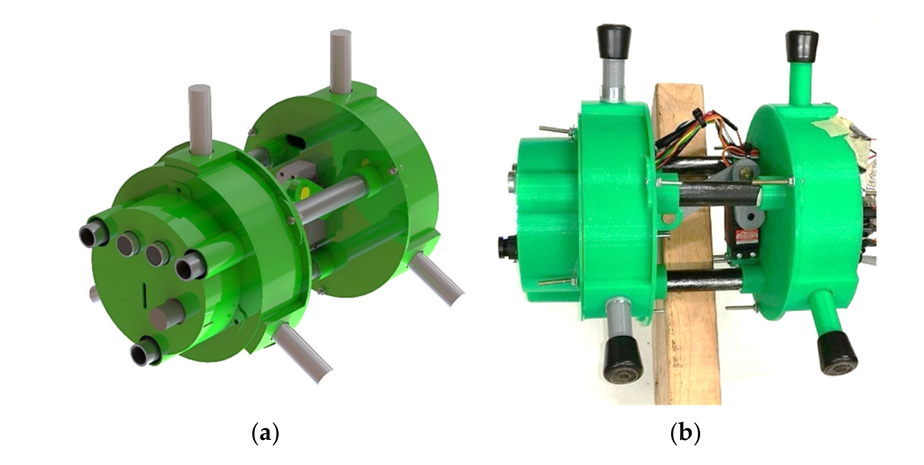
This work presents the mechanical, electrical and control design of PEIS (PipE Inspector System). This is a low-cost pipe inspector robot, which introduces a novel, low-cost locomotion mechanism that has been designed and built by the authors at University of Calabria as shown in
Figure 1. The proposed locomotion mechanisms allow to easily adapt the device to pipelines of various sizes with horizontal-, inclined-, or even vertical-motion directions.
The paper is organized as follows:
Section 2 outlines the mechanical design of the proposed PEIS device with focus on the modeling and synthesis of the locomotion mechanism.
Section 3 focuses on a dynamic analysis and simulation of PEIS to size the main components, including the mechanical parts, joints, and actuators, with proper performance to fulfil the desired task requirements.
Section 4 focuses on the robot controller to achieve a suitable and stable operation of PEIS.
Section 5 outlines the selection of proper, low-cost sensory components and details the electronics and control hardware set-up.
Section 6 reports some preliminary experimental results to demonstrate the engineering feasibility and effectiveness of the proposed design that is currently under patenting.
2. Mechanical Design
White-water pipelines are particularly subjected to occlusions caused by debris from various sources. They are usually designed using straight pipes of 200 mm to 600 mm in diameter, spaced out by 500 × 500 mm square inspector manholes. This kind of pipe-system design simplifies the proposed solution from a mechanical point of view, and it leads to a cost reduction that is a key factor for the proposed mechatronic device. The target groups of the device are, indeed, small businesses and local administrations. The mechatronic system should be easy to use to avoid the employment of highly specialized manpower. Another important feature needed is the capability to explore sloped pipes and to adapt to different pipe diameters.
After a careful analysis of the literature and the specifically addressed application task, we have identified the following main design requirements:
Suitable for pipelines with a diameter ranging from 200 to 600 mm.
Device length lower than 400 mm (for easy fitting into the 500 × 500 mm manholes).
Weight lower than 3 kg (for transportability and for avoiding damages to the pipeline.
Holding force ranging from 20 to 30 N (to avoid slippage and for avoiding damages to the pipeline).
Move along a straight pipeline (since white-water pipelines are equipped with inspection manholes at any direction change).
Speed not lower than 5 cm/s (for timely execution of tasks).
As additional requirements, the device should be user friendly and not require specific professional skills for a semi-automatic operation.
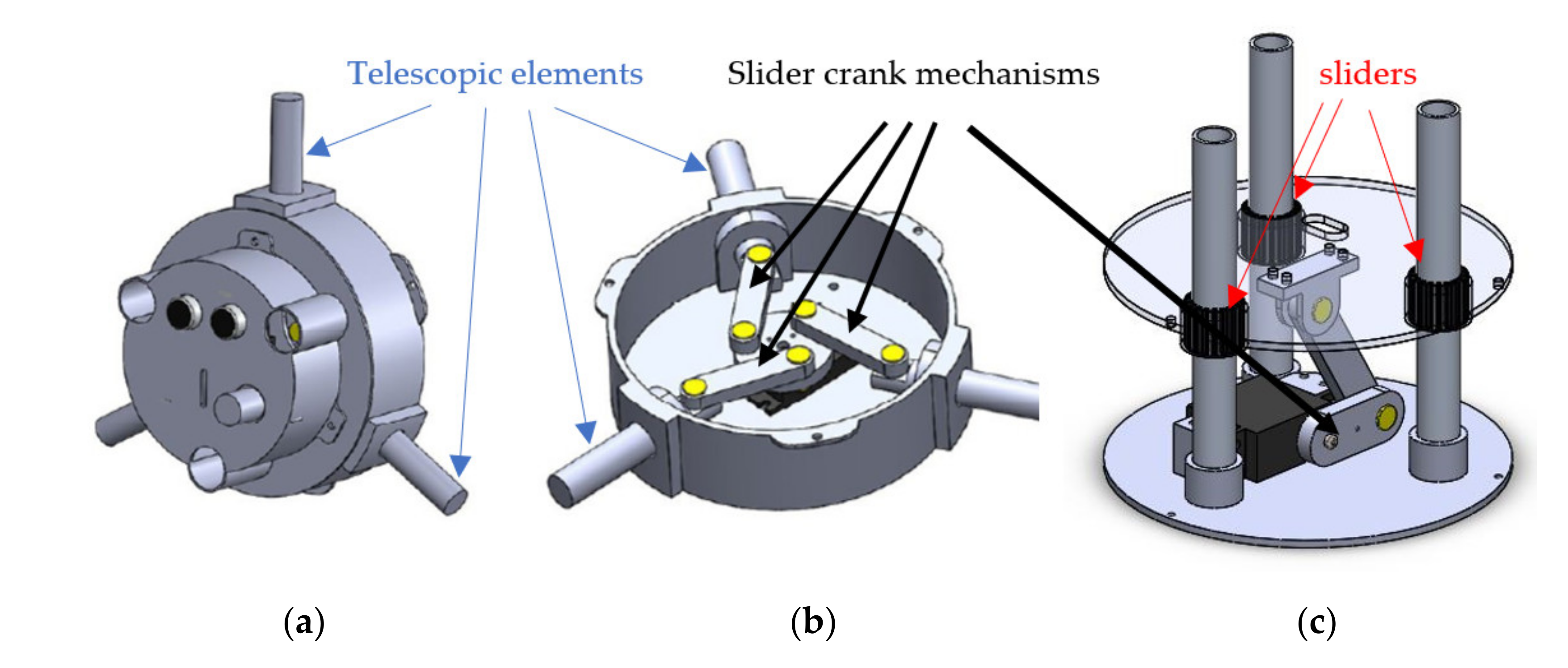
The design process is based on multiple, creative-tactic strategies, including morphological charts to help the topology synthesis, which led to a topology with three modules. Namely, the front module and the back module are the “grasping modules”, being able to hold the robot body relative to the pipe walls. A schematic view of the front module is reported in
Figure 2a. This module hosts most of the sensors and electronic components. The front and back module are equipped with telescopic elements that are driven by a specifically designed mechanism. This is schematically outlined in
Figure 2b. Each grasping module is based on a crank-shaft mechanism with three interchangeable pistons of various lengths and a single circular crank actuated by a servomotor. The rotation of the slider-crank mechanisms produces the extension of the telescopic elements, which hold firmly a module attached to the pipeline surface. The front or back module are actuated alternatively so that one of them is attached to the pipeline surface and the other one is free to move. The central body module embeds a crank-shaft mechanism actuated by a servomotor that makes the length of the robot vary, thus allowing it to move in a worm-like manner. The locomotion module is based, again, on a slider-crank mechanism that displaces the front module relative to the back module as shown in
Figure 2c. Accordingly, the locomotion strategy consists of locking one of the front or back modules and allowing the locomotion module to displace forward or backward the other module. The following sections outline the main aspects of the proposed mechanism design as based on the outlined conceptual design.
2.1. Grasping Modules
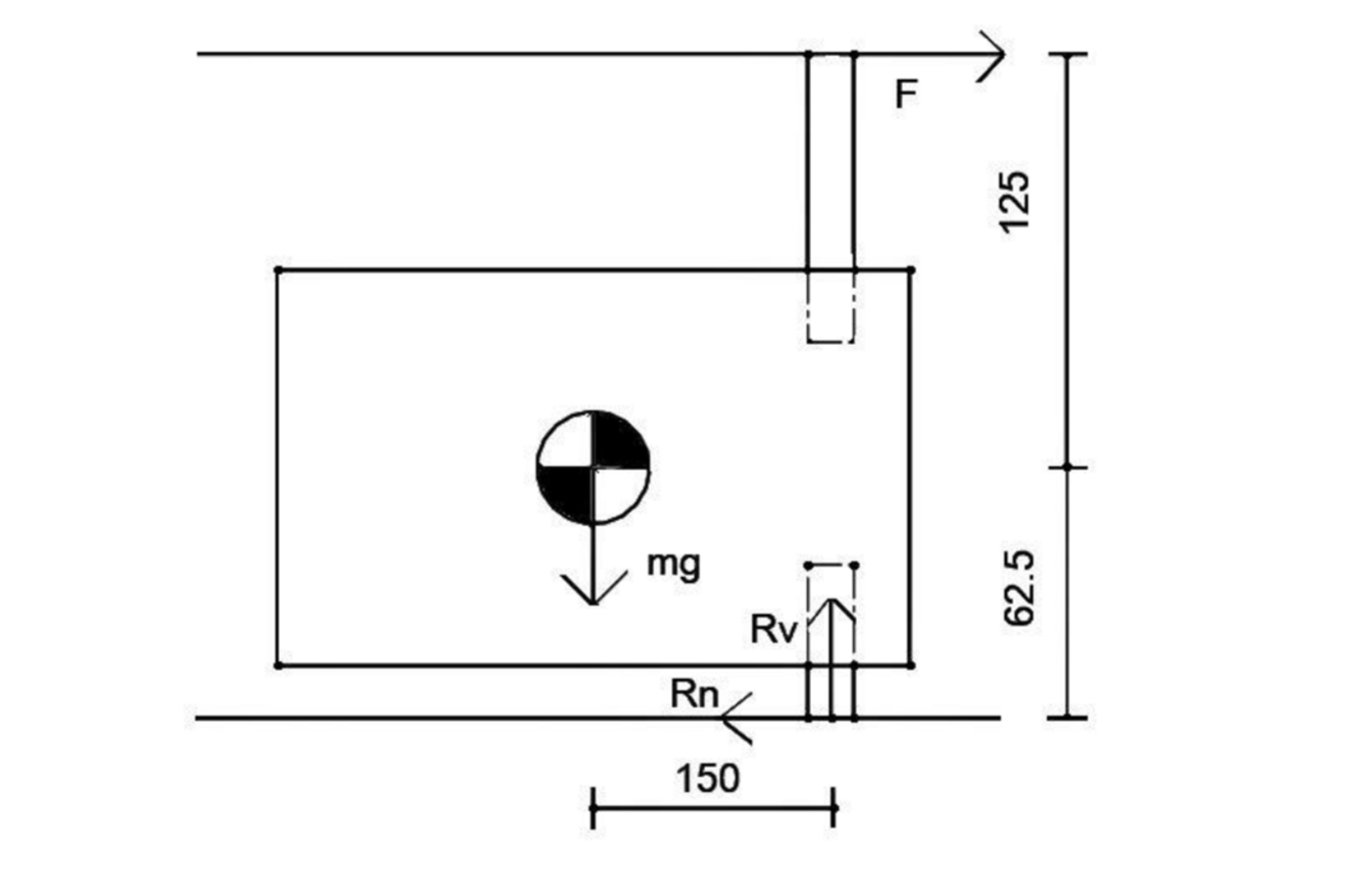
Two different configurations were studied. Namely, horizontal locomotion and vertical locomotion. One module at a time is considered, clamped to the wall of the pipe, and a Coulomb static friction coefficient of 0.4 (rubber and wet concrete) is supposed. The worst-case scenario is considered when the friction force is holding the robot as provided by a single piston. This case is outlined in the scheme in
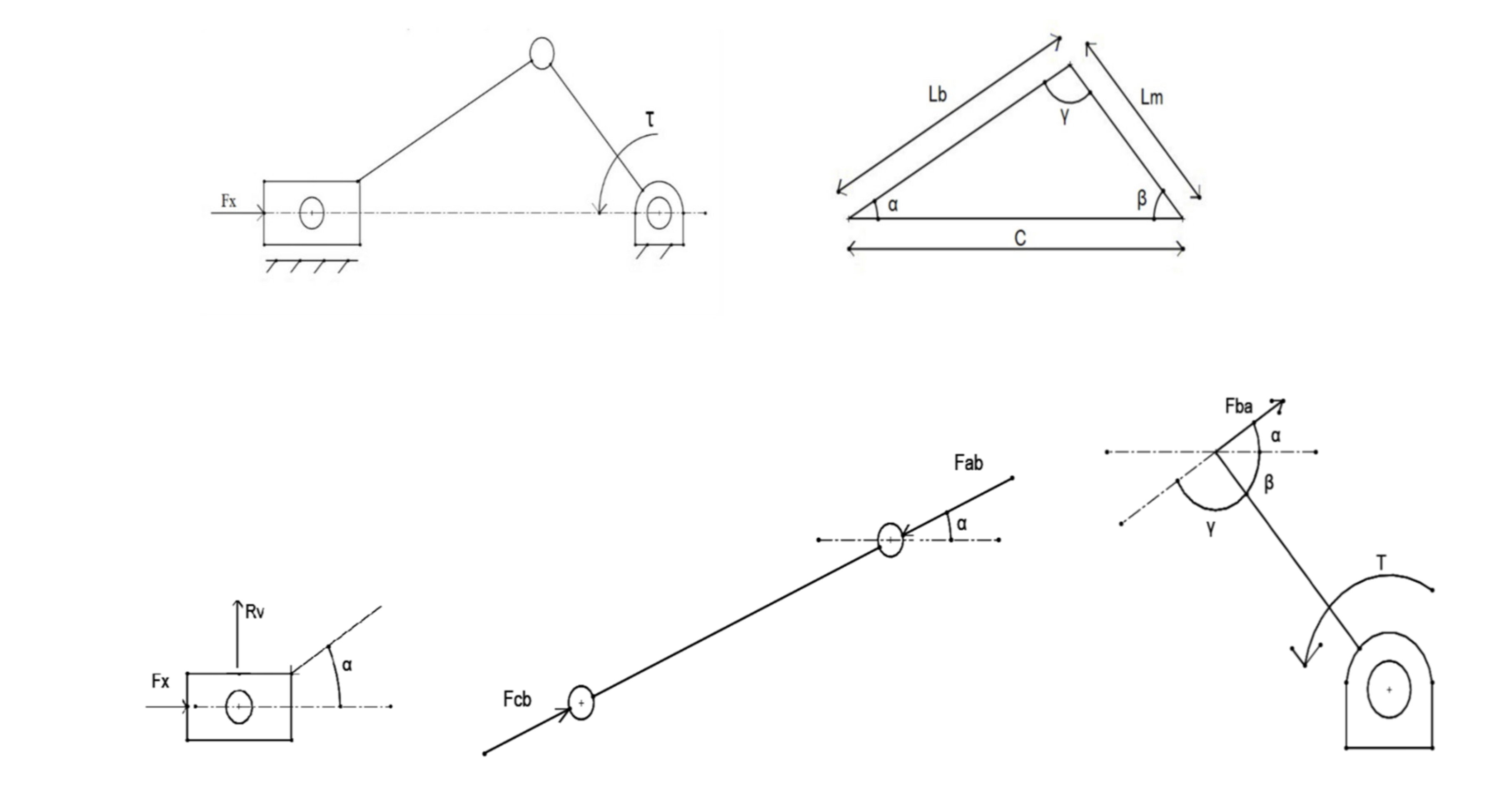
Figure 3. A 7 N force by a single piston is sufficient to prevent the robot from sliding, based on its own weight (over-estimated as equal to 1 kg), using a safety factor of two. Given the free body diagrams in
Figure 4, it is possible to write the relationship between the force exerted by the piston
and the input servomotor torque
from the equilibrium equation that can be written as
The friction force can be assumed as equal to
where
is the crank length,
the conrod length, c the length between the piston and the crank base and θ the angle between
and perpendicular to the crank. The dimensional synthesis of the mechanism consists of identifying the values of
,
, so that the mechanism can exert the desired force
while minimizing the ratio expressed in
where S expresses how close a configuration is relative to the kinematic singularity of the slider-crank mechanism. A value too close to the singularity can generate stability problems while a value too far from the singularity will result in a less compact design. It is also worth noting that an additional grasping tool could be added at the front module as proposed, for example, in [
17,
18,
19].
2.2. Locomotion Module
The proposed device moves along the pipeline by holding the pipeline wall with its front or rear module through their telescopic elements (
Figure 2). The worm-like locomotion is achieved by activation of the front and rear module, alternately. Then, the central module displaces the free module relative to the one holding the pipeline wall. Reversing the order of activation of the front and rear modules allows to reverse the motion direction. These locomotion steps are repeated cyclically until an obstruction is found or until the operator decides to stop the device. The selected driving mechanism is based on a slider-crank, whose size synthesis is performed based on the desired motion speed and the expected loading conditions defined in the design specifications.
3. Dynamic Analysis
A simplified model was developed for estimating the dynamic effects. The masses and moments of inertia of the main components have obtained from the 3D CAD model of the device. These terms are used to implement a Euler–Lagrange set of equations of motion that are solved in a Matlab environment. We assume the slider-crank mechanisms as planar mechanisms; also, we assume homogeneous materials, rigid parts, perfect constraints, and a safety factor equal to two to take into account the neglected aspects.
3.1. Horizontal Motion
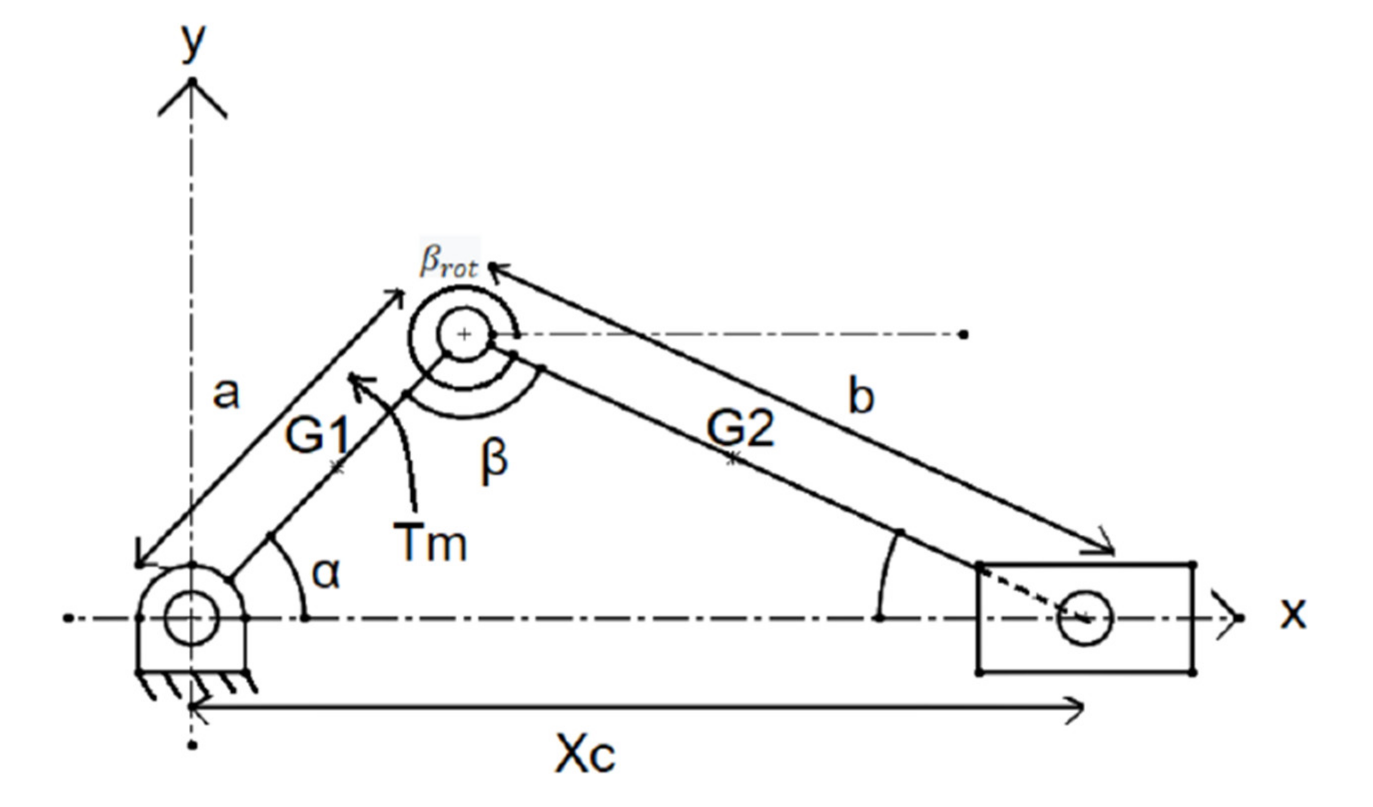
The Euler–Lagrange equation (Equation (4)) is written by considering the 1 DOF slider-crank mechanism, whose scheme is shown in
Figure 5, in the following form:
where
is the time derivative of α depicted in
Figure 4,
is the servo couple and L is the “Lagrangian” defined as the difference between the sum of the kinetic energy and the sum of the potential energy of the member in Equation (5).
where
,
,
are the
member mass, center of gravity velocity and moment of inertia, respectively.
and
are the y coordinates of the crank and the rod, respectively;
and
are the front module velocity and mass;
and
are angles time derivative; and g is the gravitational acceleration, referring to the scheme in
Figure 5.
Geometrical considerations and the substitution of previous terms lead to the motion equation in the following form:
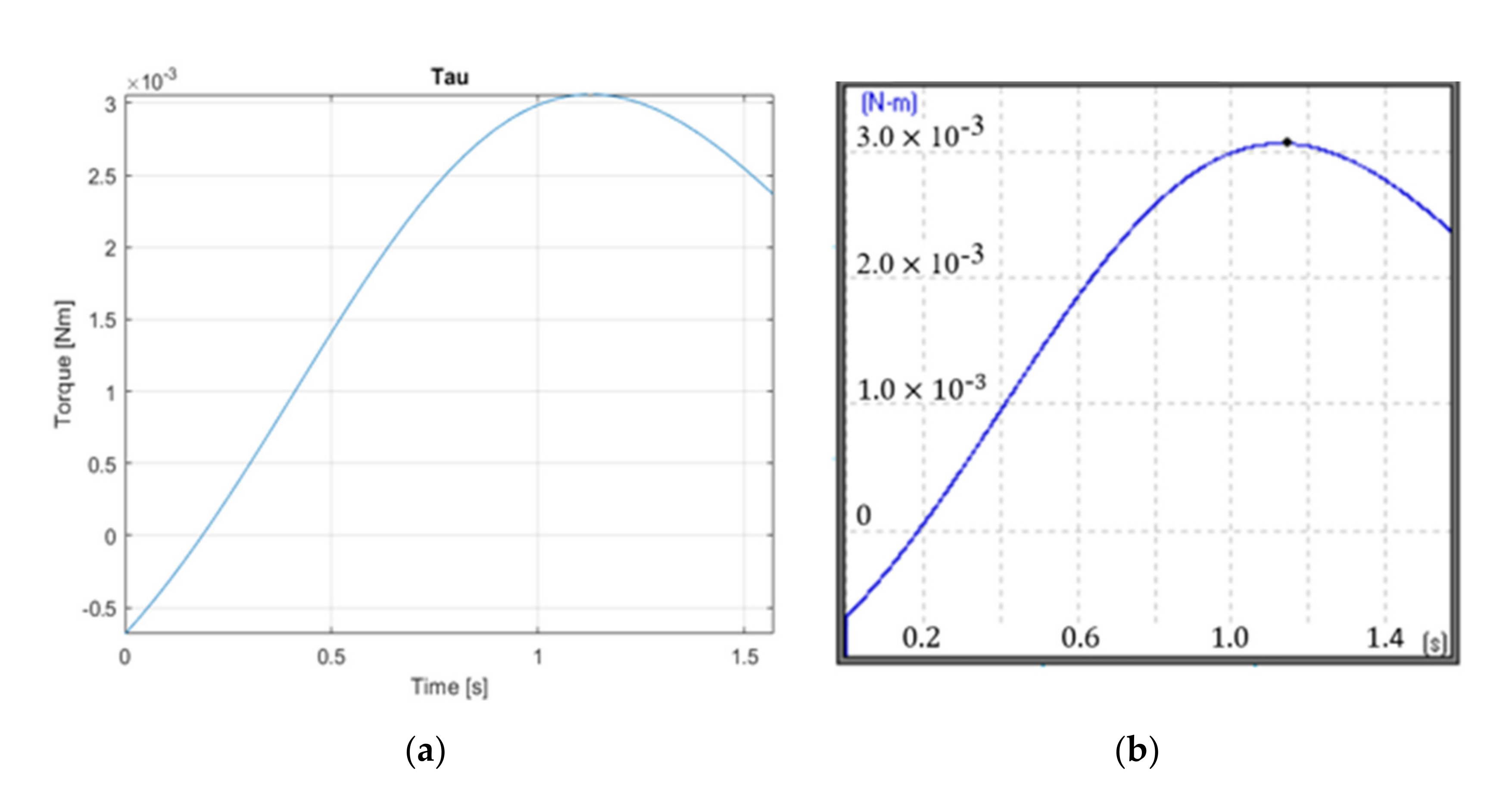
A constant rotational speed is imposed in order to check the capability of the servomotors to make the device advance and to make an estimate of the maximum motor torque needed during the operation after the transient phase. This leads to the to the results shown in
Figure 6, which are compared with similar results that were obtained by a simulation in the Working Model multibody simulation software with the same input data. The maximum required absolute torque can be estimated from
Figure 6 as about 0.003 Nm.
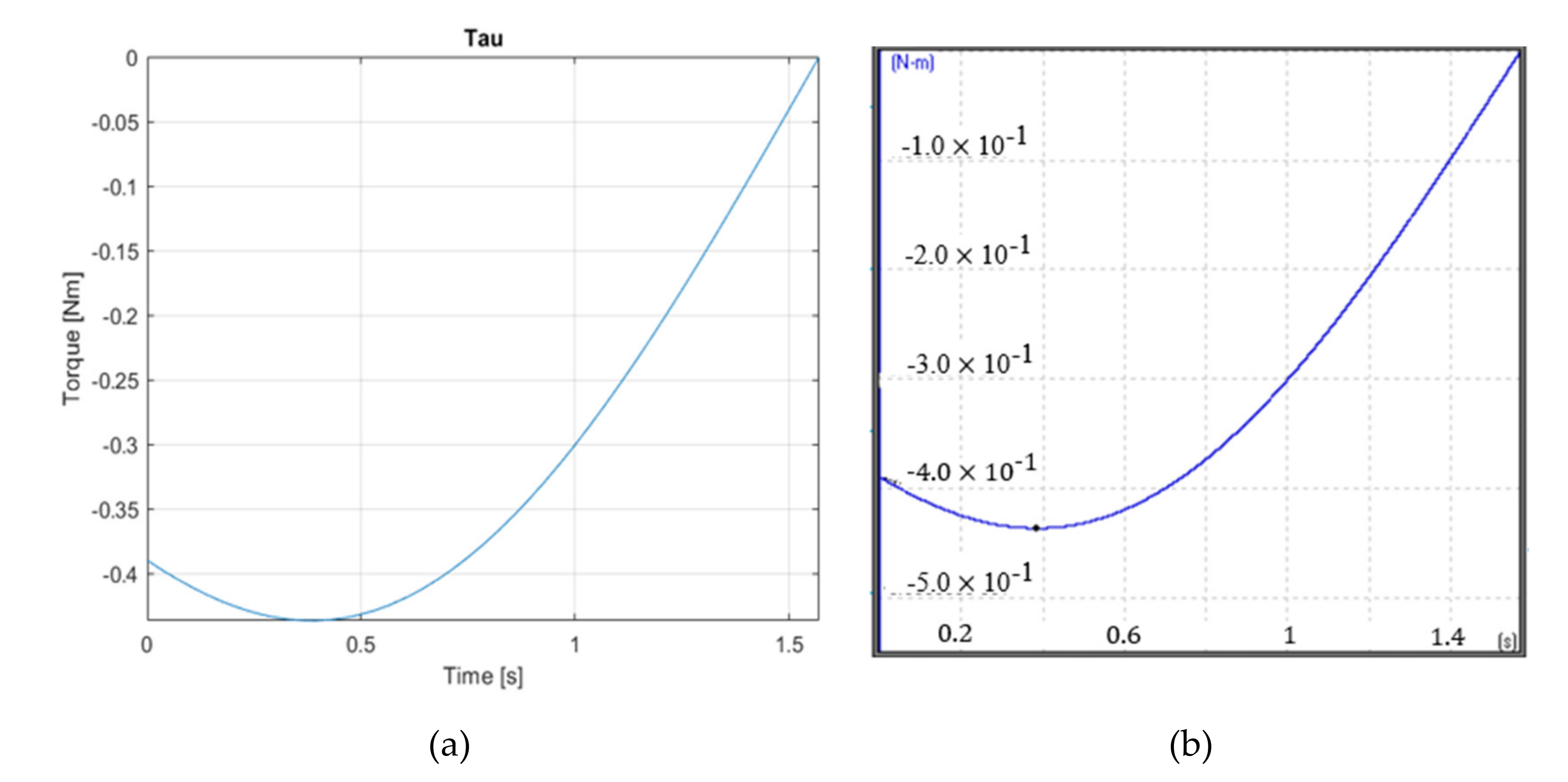
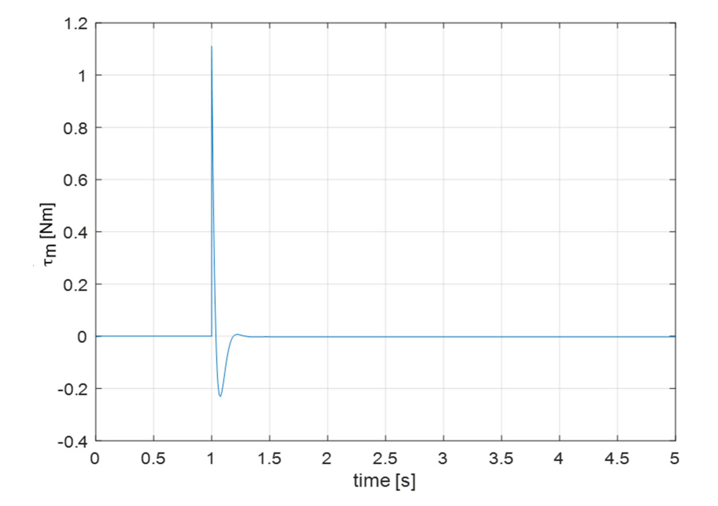
3.2. Vertical Motion
This case is addressed again by developing a proper formulation as based on the Euler–Lagrange approach. The main difference is given by the presence of the potential energy of the piston that can be computed as follows:
where
and
are the x coordinates of the crank and of the rod, while the other terms have the same formulation as reported in Equation (5). The required can be obtained by referring to the plot in
Figure 7 as having a maximum absolute value of about 0.45 Nm.
4. Control Synthesis
The motion of the system can be described with the state space representation as follows. The linearization of Equation (6)
with
state vector and
input of the physical system around the equilibrium
results in the following:
where
and, moreover,
and
are the state and input matrices, respectively. It is assumed, that the output of the system is fully measurable, therefore
. Based on Equation (6), the matrices
and
are given as follows.
The evaluation of the controllability matrix results is
, where
. Based on the Kalman rank condition for controllability, the system described with Equation (8) is controllable since
. As a result, a linear quadratic regulator (LQR) is proposed for the stabilization of the system, using the controllable system
. The LQR algorithm establishes a cost function
for the obtainment of optimal state-feedback gain
. This feedback gain minimizes the following cost function, thereby providing both good system response and feasible control action:
where
and
are the weights in Equation (10), which determine the dynamics of asymptotic stability related to the control signal
in the
th epoch. The feedback matrix is calculated as
, where
denotes the solution of the Control Algebraic Riccati equation. To ensure the reference tracking as well, the
and
matrices are employed as follows:
As a result, the control signal is obtained
, where
is the reference signal, while the matrices are given as follows:
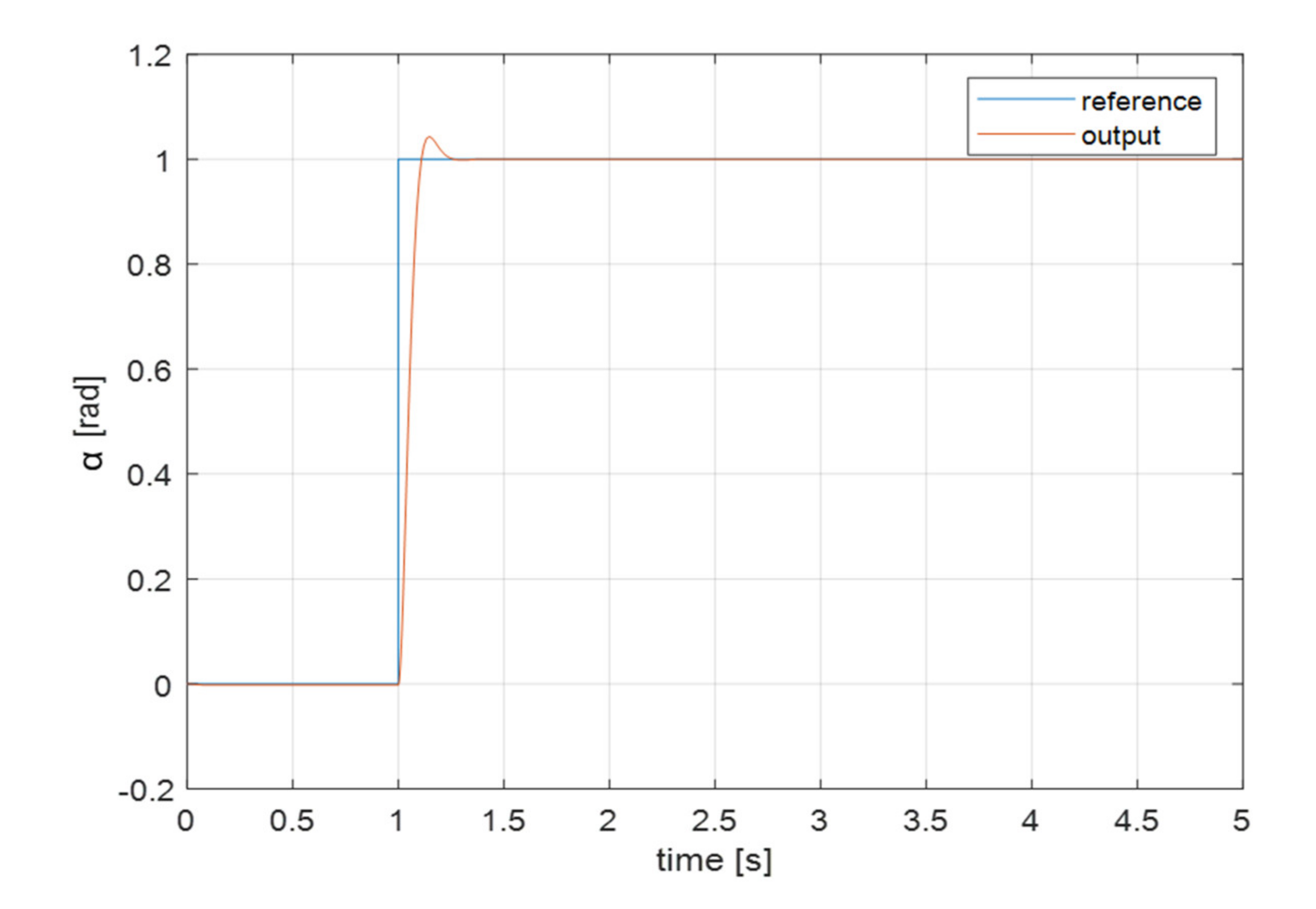
Based on Equations (9) and (12), the corresponding step response of the closed loop system is plotted in the following
Figure 8 and
Figure 9. The simulation results show that the implemented LQR strategy stabilizes the system around the reference signal.
A similar analysis can be conducted for the vertical motion. Based on Equation (7), the linearization of the equations of motion is obtained, then the state and input matrices are derived as follows:
Then, the state feedback and reference tracking matrices are calculated based on Equations (10) and (11), which are given as follows.
The aforementioned results enable the definition of the control signal , which ensures asymptotic stability.
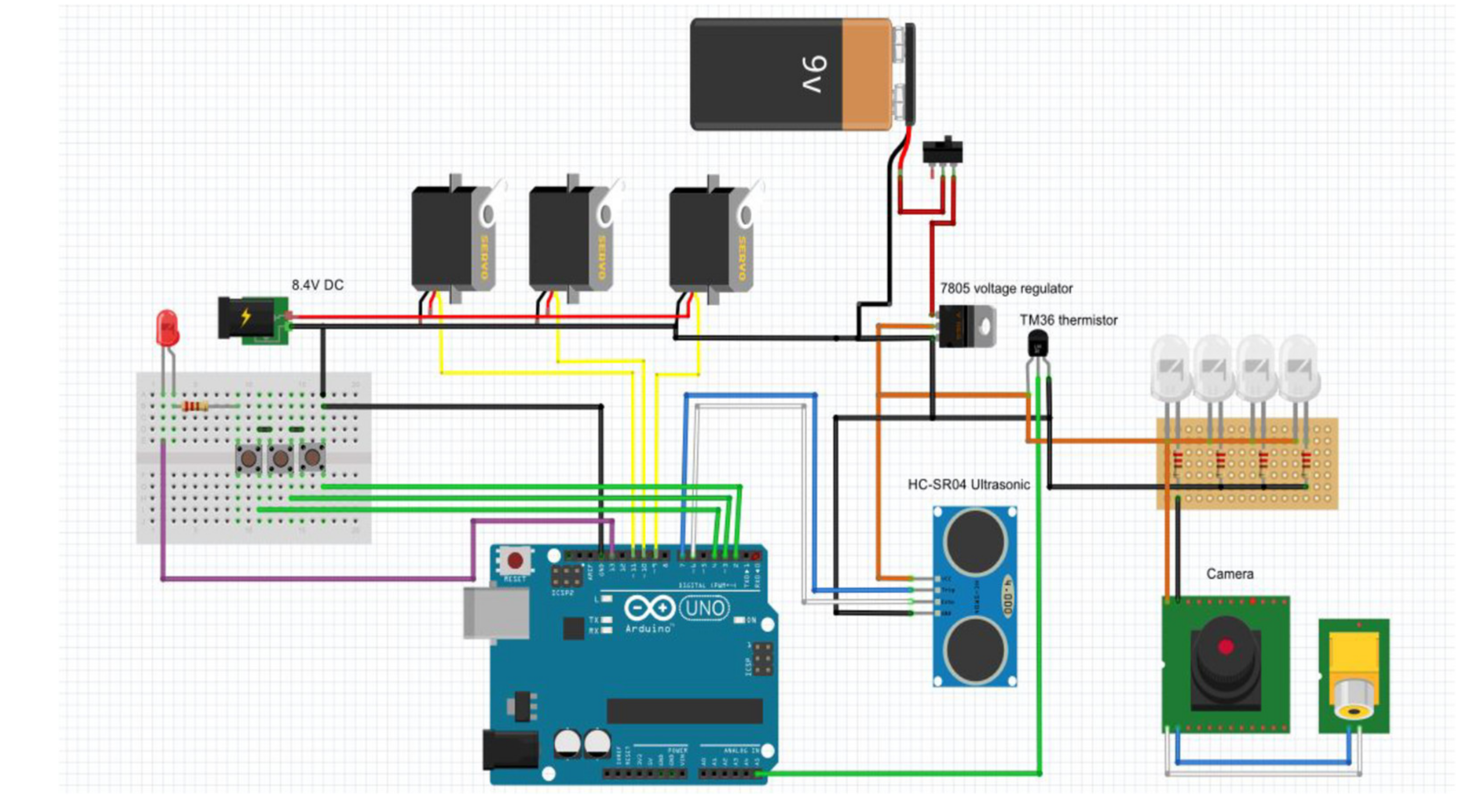
5. Sensors and Electronics
The robot is equipped with multiple sensors because it needs to obtain various information from the outside world. The sensors are powered by a battery located in the rear module and the motors are powered by an external, cabled power source. An alert LED and manual command buttons are located on a board that remains outside of the pipe during the operations. The electrical scheme is presented in
Figure 10. This control architecture can allow user-friendly operation in which an operator places the device at the beginning of a pipeline. Then, a latch switch turns on the device, including the LED lighting and all sensory feedbacks, which are streamed on the screen of a laptop and stored for further analyses. A second latch switch selects the operation direction (forward or backward). The device automatically stops when it reaches an obstruction while streaming a camera view to inspect the characteristics of an obstruction. Furthermore, the sensory feedback allows to identify the position of the obstruction relative to the initial position of the robot at the pipeline entrance.
5.1. Proximity Sensor
An essential feature of the device is being able to detect the occlusion. This is achieved using a proximity sensor located on the front module. The HC-SR04 sensor (Robot Italy, Rome) used is an ultrasonic one: the sensor is very well suited for the purpose since it is cheap, simple and works in a dark environment.
5.2. Temperature Sensor
The temperature sensor is a tmp36 (Robot Italy, Rome) and is used to obtain the in-pipe temperature. This information is used to correct the proximity sensor measurement because sound speed depends on the temperature of the medium. It is located at the front module.
5.3. Camera
The camera and the lights mounted on the front module allow to see a live feed of the inside of the tube, thus allowing an operator to evaluate the nature of the obstruction present and check for potential damages of the pipe.
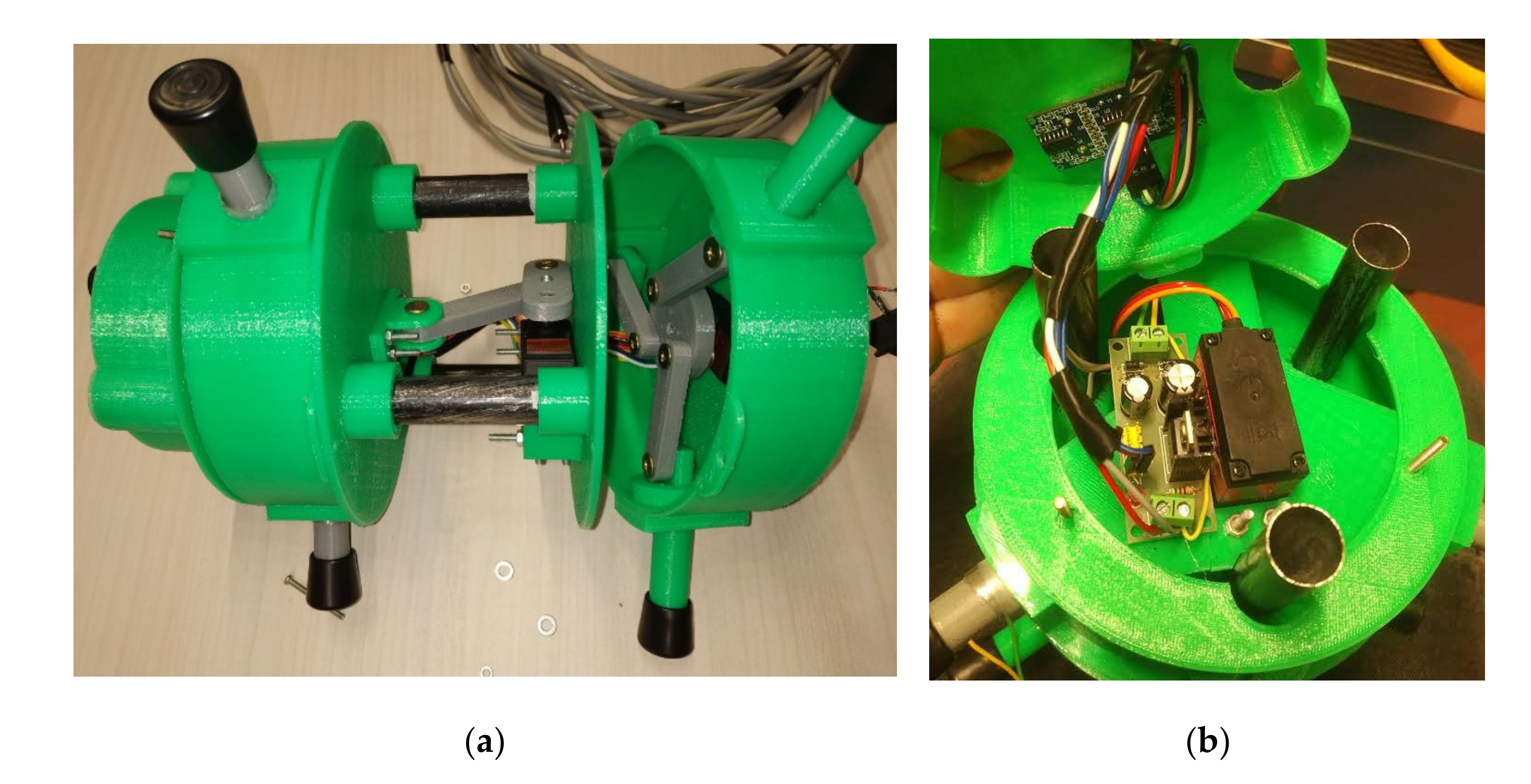
The logic implemented realizes the autonomous motion of the robot by controlling, in the right order, the positions of the servos. The control loop also checks for the presence of obstacle after each step and listen to possible user inputs. If an input is detected, the control is overridden and the user can move the robot forward or backward, while it continues to automatically grasp the pipe. If no input is received, the robot memorizes the number of steps to estimate the distance of the obstacle and allows an autonomous backward motion to bring itself to the entrance of the pipe. Details of the built prototype are reported in
Figure 11.
5.4. Inertial Measurement Unit
The electronics can be extended with an inertial measurement unit (IMU) code MPU-9250 (Robot Italy, Rome) to capture vibrations and parasitic accelerations and localize disturbances. The IMU is an extension that provides additional information of the state of the system with the accelerometer, gyroscope, and magnetometer sensors. The magnetometer can be used to identify and localize magnetic disturbances during the motion of the system. Additionally, the accelerometer and gyroscope signals can be incorporated in a state-of-the-art filter algorithm to monitor the instantaneous orientation of the system. This orientation filter is characterized by core parameters that determine the state estimation convergence; therefore, the filter parameters should be carefully chosen to ensure accurate state measurements. An efficient approach to evaluate the filter performance and to tune the filter parameters is proposed in [
20].
6. Preliminary Tests
The preliminary tests were carried out by using a 3D-printed proof-of-concept prototype as proposed in [
21]. The experimental tests consisted of the following steps:
- -
Place the device at the beginning of a pipeline.
- -
Turn on the device with a latch switch. This activates the device including all sensory feedbacks that are streamed on the screen of a laptop and stored for further analyses.
- -
Turn on the latch switch, selecting the semiautomatic forward motion. The device automatically stops when it reaches an obstruction while streaming a camera view to inspect the characteristics of the obstruction.
- -
Upon reaching an obstruction, the operator can visually inspect the obstruction by using video streaming. Furthermore, the sensory feedback allows to identify the position of the obstruction relative to the initial position of the robot at the pipeline entrance.
- -
Turn on the latch switch, selecting the semiautomatic backward motion. The device automatically stops when it is back at the initial position.
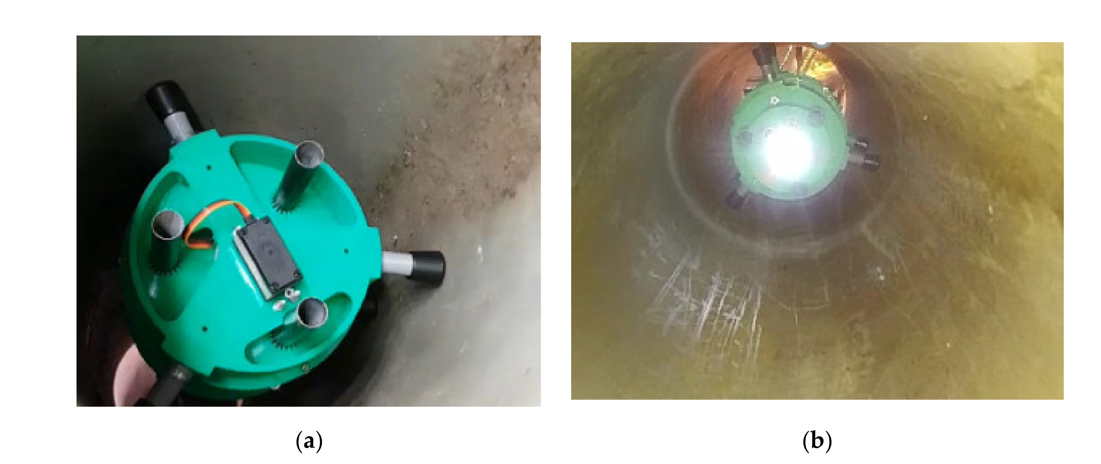
The same operation strategy was implemented for several tests. In particular, the PEIS prototype was able to advance in pipelines that were horizontal, but also in a sloped pipeline and even in a vertical pipeline as shown in
Figure 11 and
Figure 12. The locomotion principle was very effective in all operation conditions with a simple operation and no grip loss. Various obstructions were successfully detected, and the LED light, placed on the front module, allowed for seeing clearly through the camera. The drive current and servomotor position/velocity feedback were monitored during operation. All the obtained readings were within maximum values in the range 0.6 to 0.8 amperes, and their values are compatible with the simulated values, even exceeding the performance expectations. The temperature and distance detection were obtained with readings in the expected error range. The manual control worked well with no appreciable delay. Several different types of obstructions were tested in terms of shape, size and position of obstacles in the pipeline. The used ultrasonic sensors were proven to be very effective in identifying the obstructions, regardless of their shape, size and position. The detection distance can be adjusted starting from a range of 1 m. Then, the operator can use video streaming to further inspect the characteristics of the obstruction.
The performed tests successfully demonstrated the engineering feasibility of the proposed design as well as the user-friendliness of the proposed design, which can be operated without professional skills in a semi-automatic operation. Note that the aim of this work consisted of proposing a conceptual design. In future, we do plan to design an improved prototype and carry out more experiments as based on the outcomes of this work. Additionally, we do plan to perform safety tests, such as those outlined in [
22].
7. Conclusions
This paper outlines the design of a PEIS novel robotic system for semi-automatic inspection and white-water in-pipe obstruction removal. The proposed device is characterized by a lightweight structure and high transportability. It is composed of a front, a rear and a central module that realize a worm-like locomotion of the robot with a specifically designed driving mechanism. Proper modeling and numerical simulations were carried out to complete the design of the prototype. The proposed prototype is integrated with control and sensory components and was preliminarily validated in laboratory tests under various operation conditions with horizontal and even vertical pipelines. All the tests were successful. The obtained preliminary results demonstrated the engineering feasibility and effectiveness of the proposed design with satisfactory in-pipe motion and inspection with proper visual and sensory detection of obstacles by means of the onboard camera, proximity sensor, temperature sensor, and IMU sensor. Further investigations will be carried out in the near future to integrate further sensory feedback as well as to test the device in real operation conditions.
8. Patents
A specific Italian patent application has been made for the PEIS design as reported in [
23].
Author Contributions
Conceptualization, M.M.S., A.G., L.M., G.P. and G.C.; methodology, M.M.S., A.G., L.M., G.P. and G.C.; investigation, M.M.S., A.G., L.M., G.P. and G.C.; writing—original draft preparation, M.M.S., P.O., G.C.; supervision, G.C. All authors have read and agreed to the published version of the manuscript.
Funding
This work was partially supported by the EFOP-3.6.1-16-2016-00003 project, which is co-financed by the European Union. Peter Odry was also partially supported by the 2020-4.1.1-TKP2020 program.
Institutional Review Board Statement
Not applicable.
Informed Consent Statement
Not applicable.
Data Availability Statement
Not applicable.
Conflicts of Interest
The authors declare no conflict of interest.
References
- Aspragathos, N.; Moulianitis, V.; Koustoumpardis, P. Special Issue on Human–Robot Interaction (HRI). Robotica 2020, 38, 1715–1716. [Google Scholar] [CrossRef]
- Worley, R.; Anderson, S. Topological robot localization in a pipe network. In Proceedings of the UKRAS20 Conference: “Robots into the Real World, Online conference, 7 April 2020; EPSRC UK-RAS Network. pp. 59–60. [Google Scholar]
- Carbone, G.; Malchikov, A.; Ceccarelli, M.; Jatsun, S. Design and Simulation of Kursk Robot for in-Pipe Inspection. In Proceedings of the 10th IFToMM International Symposium on Science of Mechanisms and Machines SYROM’09, Brasov, Romania, 12–15 October 2009; Springer: Dordrecht, The Netherlands, 2009; pp. 103–114. [Google Scholar]
- Roman, H.T.; Pellegrino, B.A.; Sigrist, W.R. Pipe crawling inspection robot: An overview. IEEE Trans. Energy Convers. 1993, 8, 576–583. [Google Scholar] [CrossRef]
- Nagano, S.; Oka, Y. Application of In-Pipe Visual Inspection Robot to Piping Internal Surface Lining. In Proceedings of the 5th International Symposium on Robotics in Construction, Tokyo, Japan, 6–8 June 1988; pp. 897–906. [Google Scholar]
- Pfeiffer, F.; Robmann, T.; Loffer, K. Control of a Tube Crawling Machine. In Proceedings of the International Conference on Control of Oscillations and Chaos, S. Petersburg, Russia, 5–7 July 2000; Volume 3, pp. 586–591. [Google Scholar]
- Bertetto, A.M.; Ruggiu, M. In-pipe inch-Worm Pneumatic Flexible Robot. In Proceedings of the IEEE/ASME International Conference on Advanced Intelligent Mechatronics, Como, Italy, 8–12 July 2001; Volume 2, pp. 1226–1231. [Google Scholar]
- Anthierens, C.; Ciftci, A.; Betemps, M. Design of an Electro Pneumatic Micro Robot for In-Pipe Inspection. In Proceedings of the IEEE International Symposium on Industrial Electronics, Bled, Slovenia, 12–16 July 1999; Volume 2, pp. 968–972. [Google Scholar]
- Tourajizadeh, H.; Boomeri, V.; Rezaei, M.; Sedigh, A. Dynamic Optimization of a Steerable Screw In-pipe Inspection Robot Using HJB and Turbine Installation. Robotica 2020, 38, 2001–2022. [Google Scholar] [CrossRef]
- Liang, L.; Chen, B.; Tang, Y.; Xu, Y.; Liu, Y. Operational performance analysis of spiral capsule robot in multiphase fluid. Robotica 2019, 37, 213–232. [Google Scholar] [CrossRef]
- Tang, Z.; Lu, J.; Wang, Z.; Ma, G.; Chen, W.; Feng, H. Development of a New Multi-cavity Pneumatic-driven Earthworm-like Soft Robot. Robotica 2020, 38, 2290–2304. [Google Scholar] [CrossRef]
- Zhou, F.; Xu, X.; Xu, H.; Chang, Y.; Wang, Q.; Chen, J. Implementation of a Reconfigurable Robot to Achieve Multimodal Locomotion Based on Three Rules of Configuration. Robotica 2020, 38, 1478–1494. [Google Scholar] [CrossRef]
- Roy, R.; Ghoshal, D. Grey Wolf Optimization-Based Second Order Sliding Mode Control for Inchworm Robot. Robotica 2020, 38, 1539–1557. [Google Scholar] [CrossRef]
- Saab, W.; Racioppo, P.; Kumar, A.; Ben-Tzvi, P. Design of a miniature modular inchworm robot with an anisotropic friction skin. Robotica 2019, 37, 521–538. [Google Scholar] [CrossRef] [Green Version]
- Carbone, G.; Ceccarelli, M. A low-cost easy-operation hexapod walking machine. Int. J. Adv. Robot. Syst. 2008, 5, 161–166. [Google Scholar] [CrossRef]
- Carbone, G.; Shrot, A.; Ceccarelli, M. Operation strategy for a low-cost easy-operation cassino hexapod. Appl. Bionics Biomech. 2007, 4, 149–156. [Google Scholar] [CrossRef] [Green Version]
- Yao, S.; Ceccarelli, M.; Carbone, G.; Dong, Z. Grasp Configuration Planning for a Low-Cost and Easy-Operation Underactuated Three-Fingered Robot Hand. Mech. Mach. Theory 2018, 129, 51–69. [Google Scholar] [CrossRef]
- Hernández-Martínez, E.E.; Ceccarelli, M.; Carbone, G.; López-Cajún, C.S.; Jáuregui-Correa, J.C. Characterization of a cable-based parallel mechanism for measurement purposes. Mech. Based Des. Struct. Mach. 2010, 38, 25–49. [Google Scholar] [CrossRef]
- Carbone, G.; Ceccarelli, M. Experimental Tests on Feasible Operation of a Finger Mechanism in the LARM Hand. Mech. Based Des. Struct. Mach. 2008, 36, 1–13. [Google Scholar] [CrossRef]
- Odry, Á. An Open-Source Test Environment for Effective Development of MARG-Based Algorithms. Sensors 2021, 21, 1183. [Google Scholar] [CrossRef]
- Cafolla, D.; Ceccarelli, M.; Wang, M.F.; Carbone, G. 3D printing for feasibility check of mechanism design. Int. J. Mech. Control 2016, 17, 3–12. [Google Scholar]
- Cordero, C.A.; Carbone, G.; Ceccarelli, M.; Echávarri, J.; Muñoz, J.L. Experimental tests in human-robot collision evaluation and characterization of a new safety index for robot operation. Mech. Mach. Theory 2014, 80, 184–199. [Google Scholar] [CrossRef] [Green Version]
- Salvatore, M.M.; Galloro, A.; Muzzi, L.; Pullano, G.; Carbone, G. Device for Automatic Monitoring of Occlusions in White Water Pipelines. Italian Patent Application No. 102021000002651, 5 February 2021. (In Italian). [Google Scholar]
| Publisher’s Note: MDPI stays neutral with regard to jurisdictional claims in published maps and institutional affiliations. |
© 2021 by the authors. Licensee MDPI, Basel, Switzerland. This article is an open access article distributed under the terms and conditions of the Creative Commons Attribution (CC BY) license (https://creativecommons.org/licenses/by/4.0/).


 ,
, 


