Mechatronic Re-Design of a Manual Assembly Workstation into a Collaborative One for Wire Harness Assemblies

 , ,
, ,  ,
,  and
and
Abstract
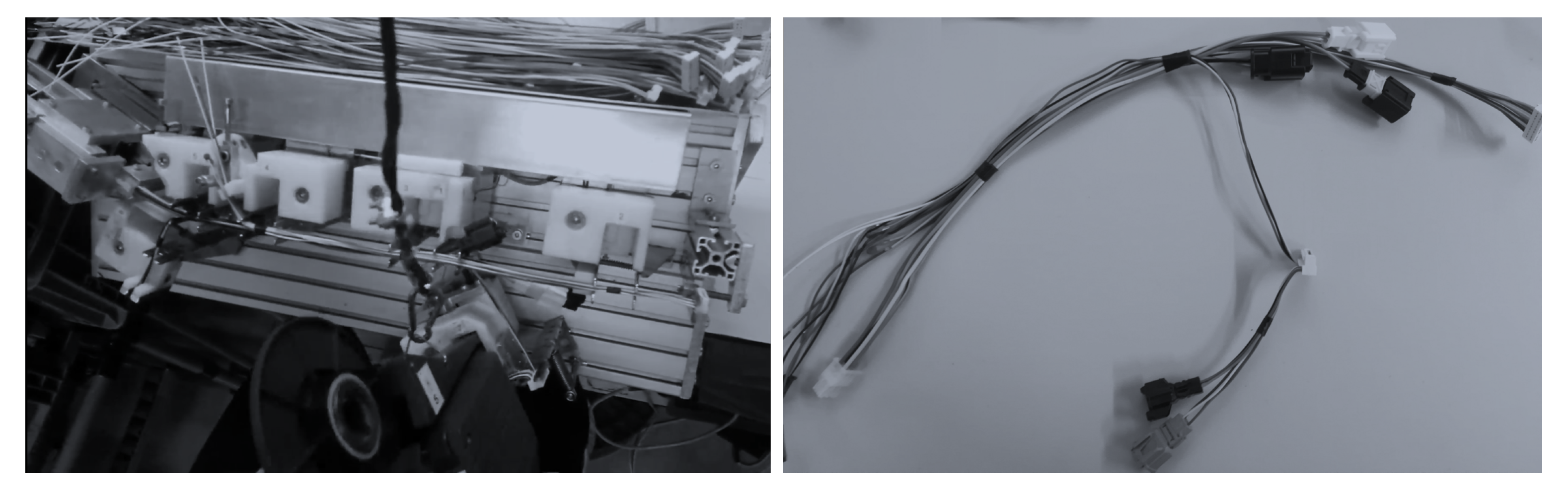
:1. Introduction
2. Case Study Objectives
- improving the productivity, i.e., a cycle time shorter than the one of the current manual process;
- improving the operator’s physical work conditions, i.e., improve the physical ergonomics; and
- guaranteeing a safe collaboration with humans.
3. Methods
- Problem definition
- Background research
- Requirement specification
- Conceptual design
- Detailed design
- Assessment of requirement satisfaction
- Severity : It denotes the severity of possible harm as an outcome from the identified hazard and can assume an integer value between one and four.
- Frequency : It evaluates the average interval between frequency of risk exposure and its duration and can assume an integer value between two and six.
- Probability : It is the probability of occurrence of a hazardous event and can assume an integer value between one and five.
- Avoidance : It is the possibility of avoiding or limiting harm and can assume an integer value equal to one, three or five.
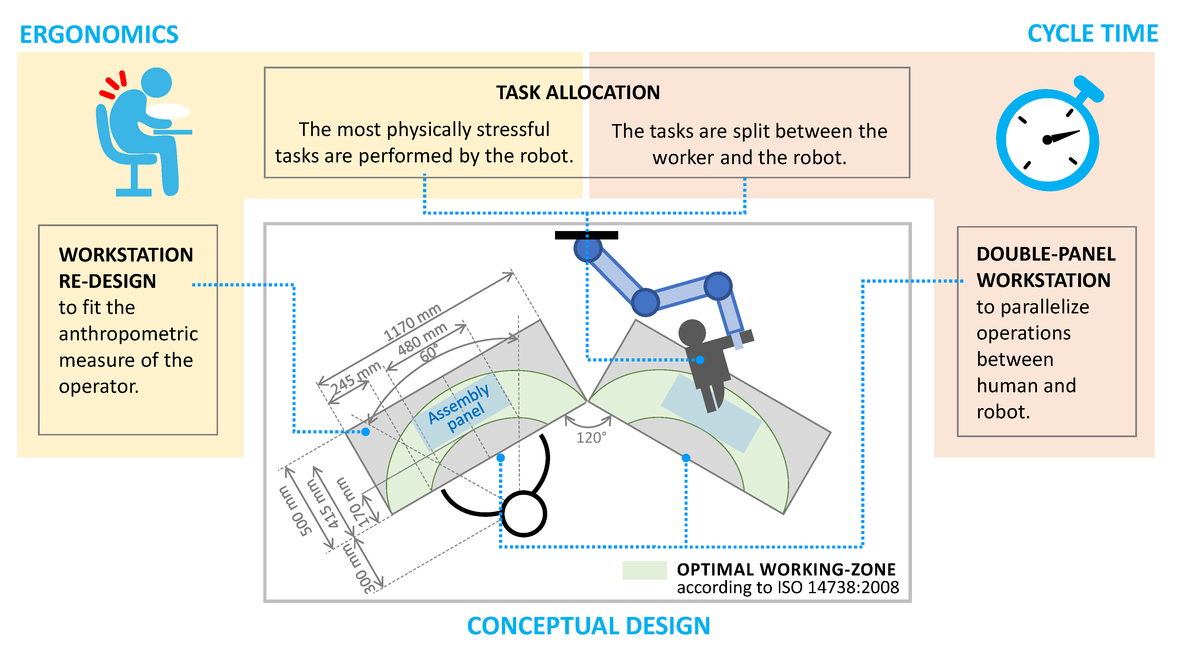
4. Conceptual Design
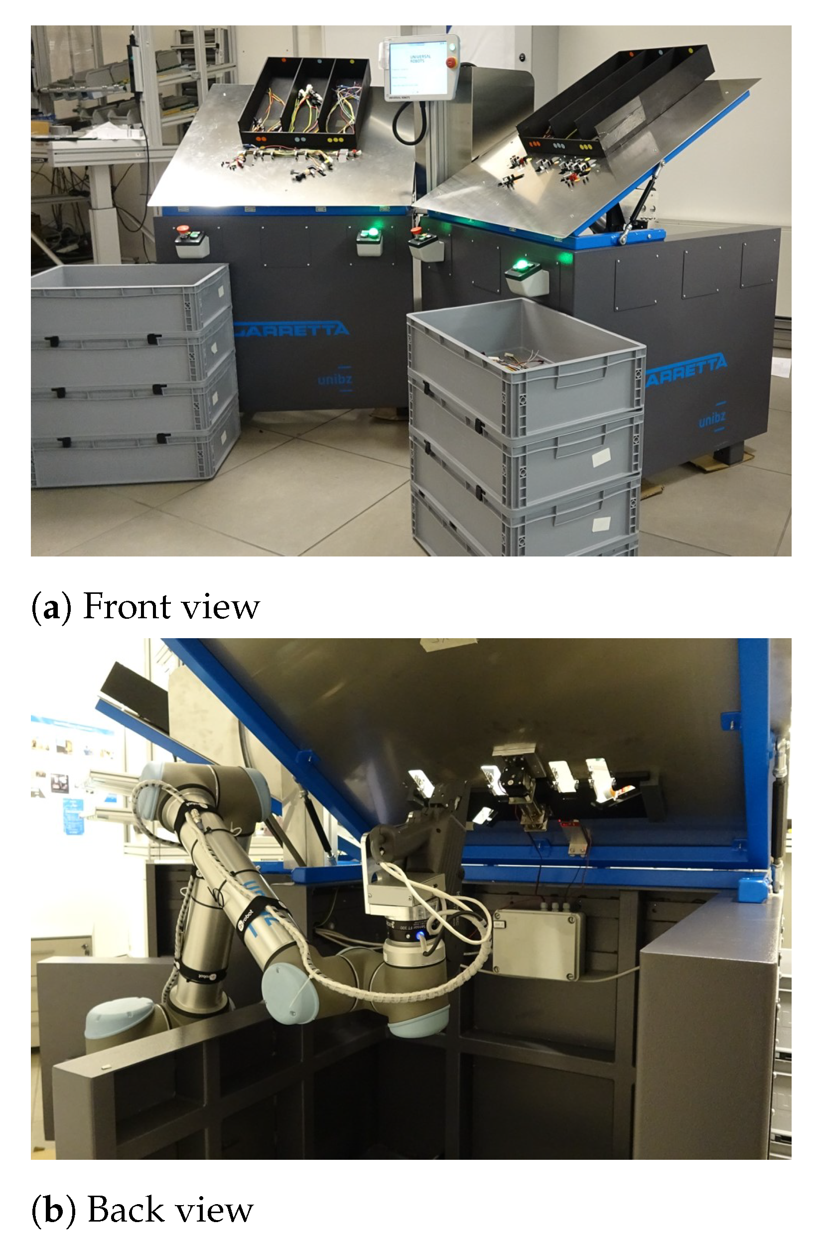
5. Solution Implementation and Prototyping
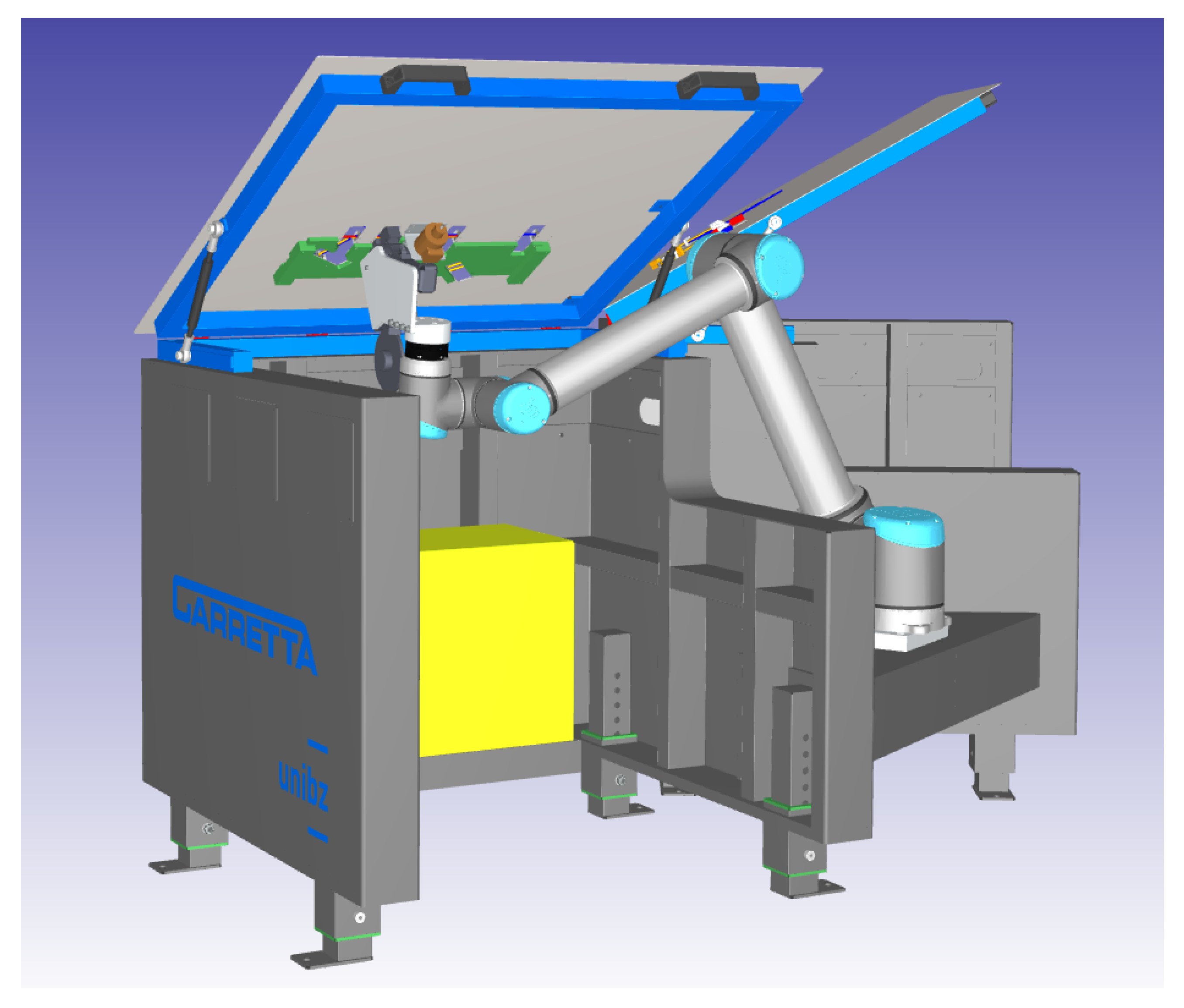
- Two benches
- Two assembly panels
- Six boxes for the storage of the wires to be assembled and two boxes for the assembled harnesses
- A collaborative robot, a Universal Robot UR10
- An end-effector: the taping pistol Kaba Tec KTH Spot 9
- Two wire locking systems (one per panel)
- Buttons and lights to interface with the operator
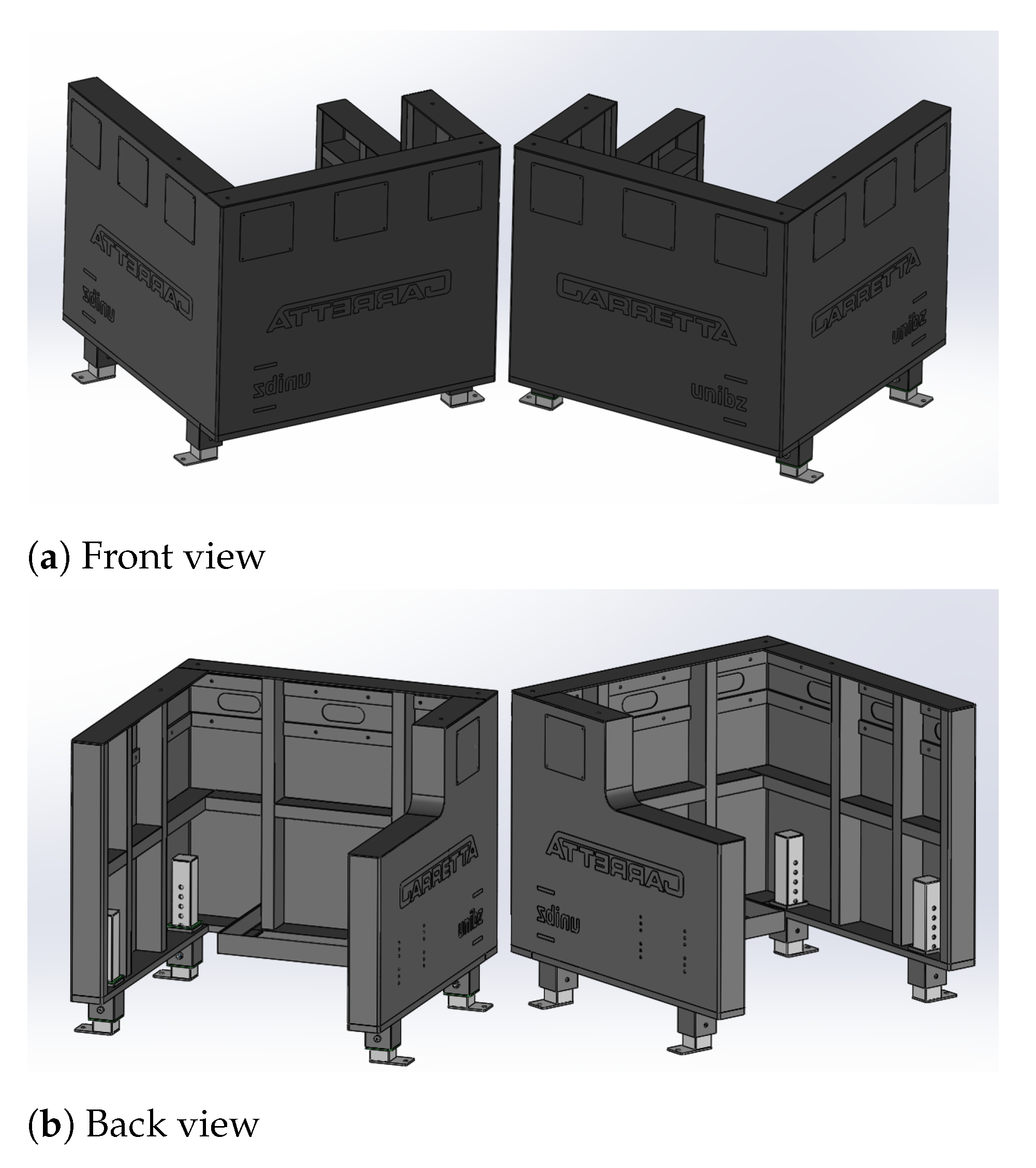
5.1. Metallic Carpentry: Benches and Assembly Panels
5.2. Storage Boxes
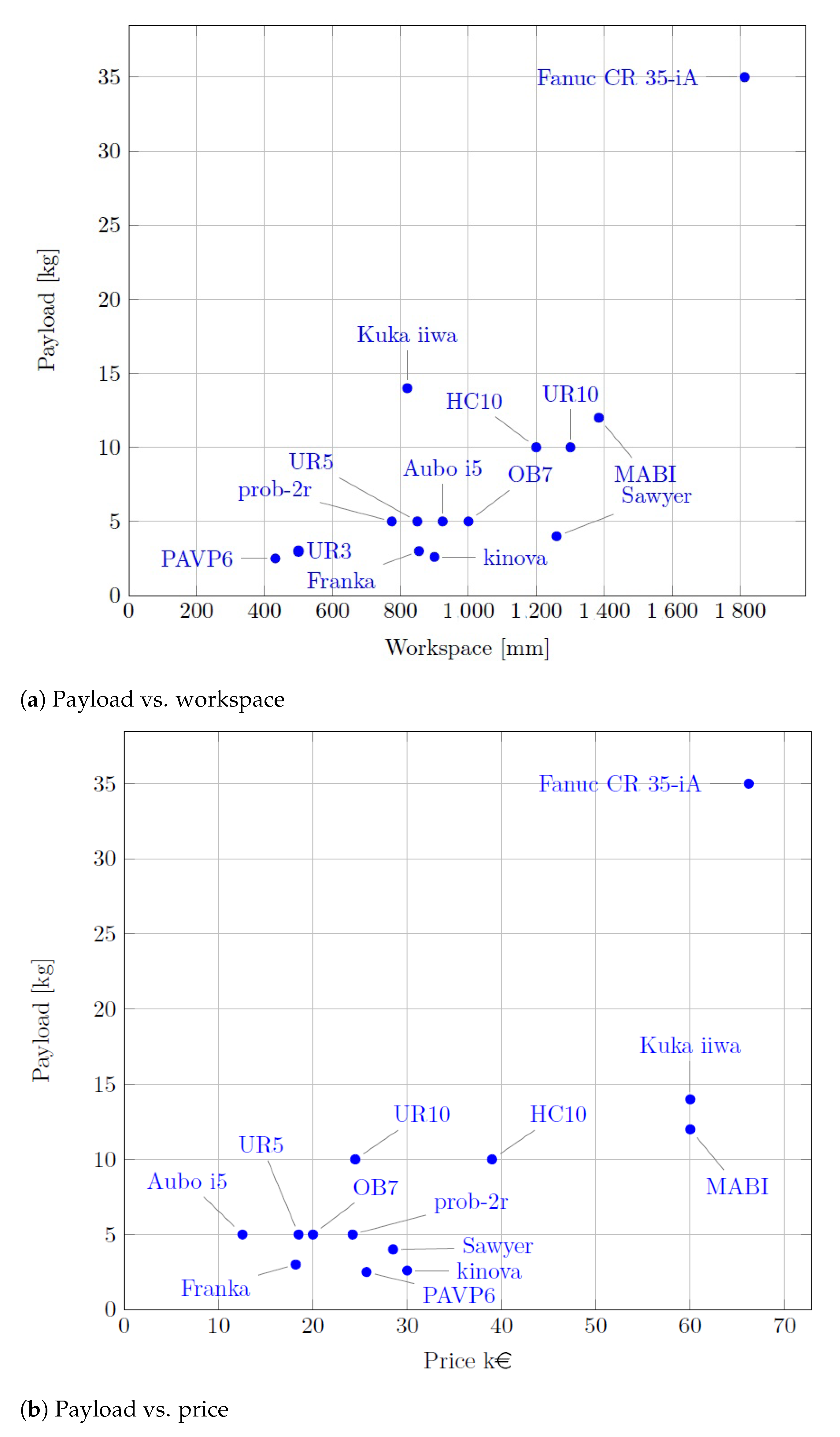
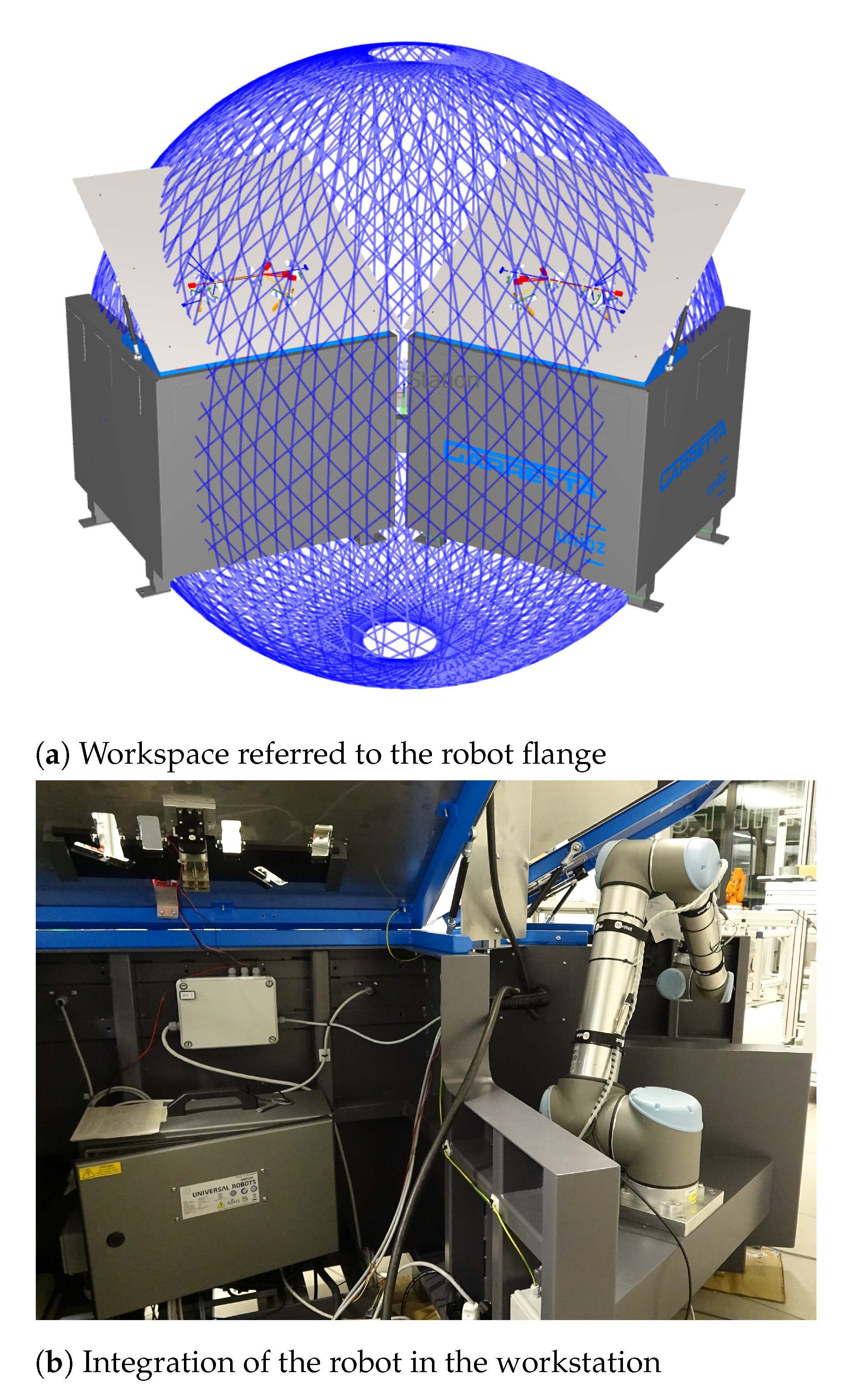
5.3. Collaborative Robot Placement and Selection
- The working area of each panel is quite small (about 450 mm × 220 mm).
- The robot must cover a large area moving between the two panels (the minimum distance between their farthest points is 1.6 m). This means that its dimension will not be compact.
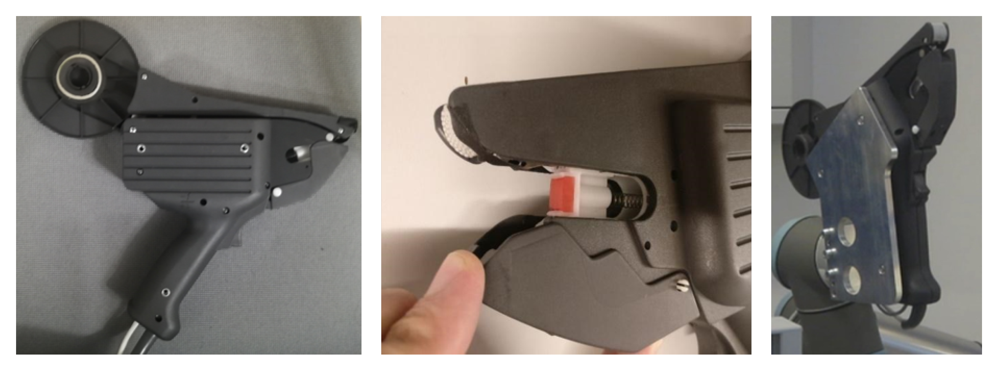
5.4. End-Effector
- Start taping.
- Check tape fault (roll end and/or tape torn). This condition has been managed by bringing the robot in a maintenance position and informing the operator in charge by means of an optical signaling device and a pop-up on the teaching pendant of the robot.
- Status of the taping operation based on the work cycle of the motor.
- Status of the safety device, i.e., the tilting component on the tip of the pistol (see the central picture in Figure 8). The pistol motor starts only if it is in a closed position.
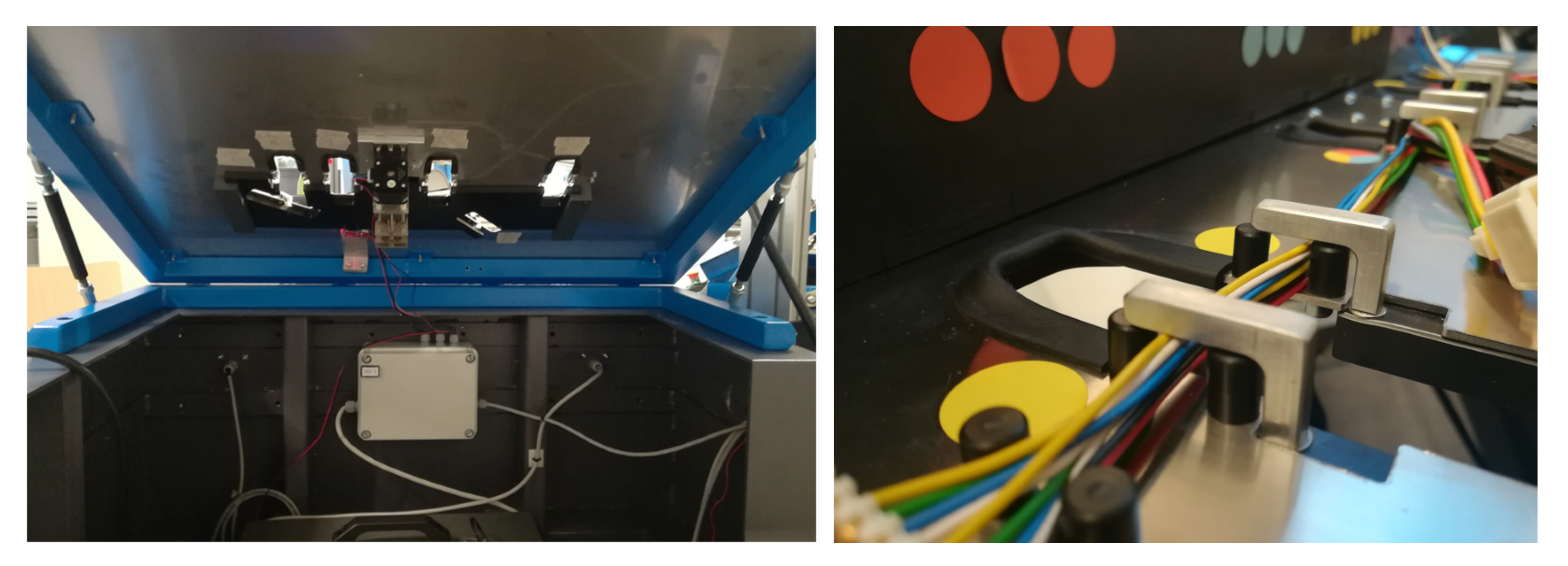
5.5. Locking System
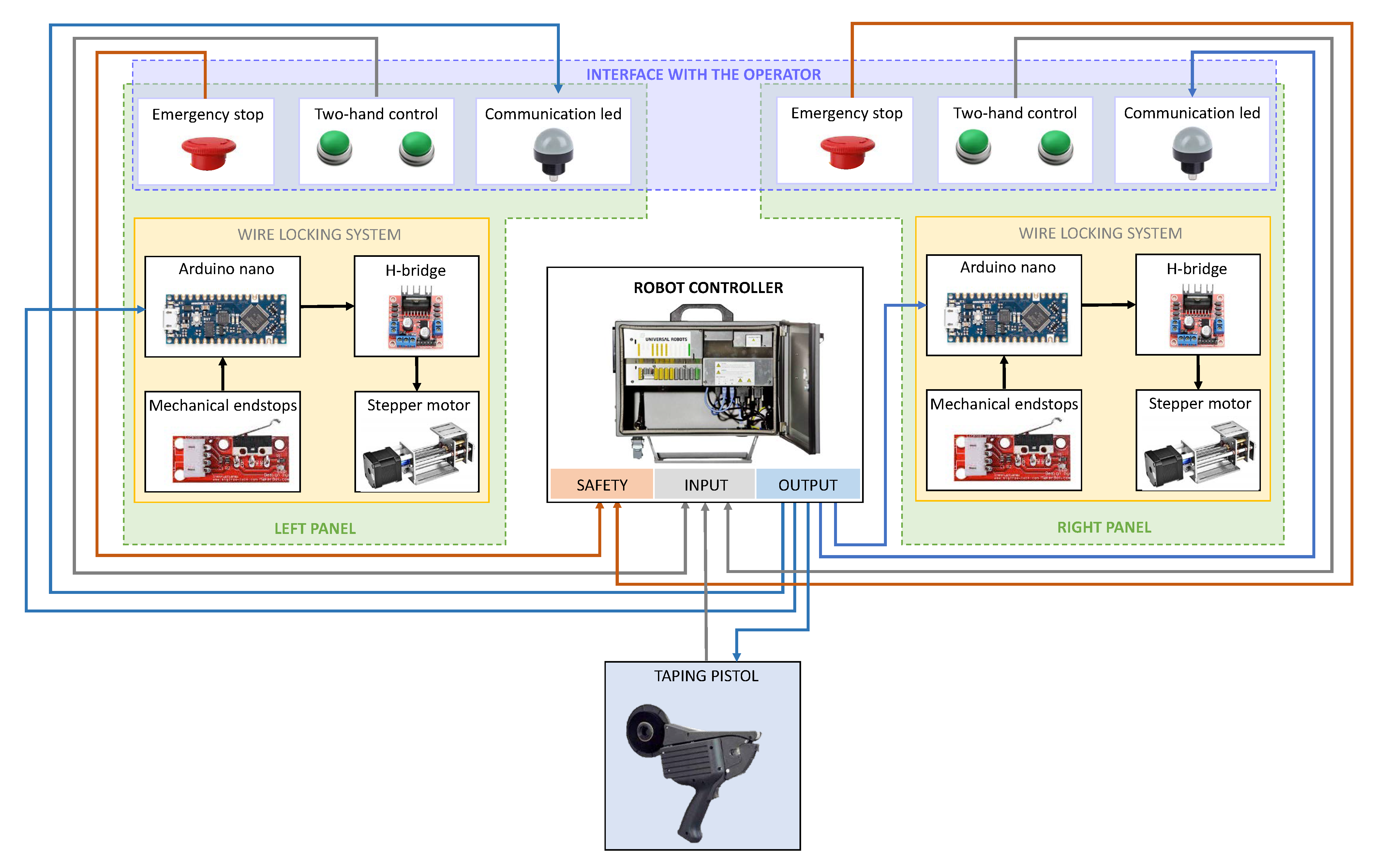
5.6. Workstation Architecture
- The worker picks the first two bundles of wires with connectors and inserts them into the assembly jigs of Panel 1.
- While the worker removes the previous assembled wire harness from Panel 2, the robot tapes the wire harness on Spot 1 of Panel 1.
- The worker picks and inserts the third bundle of wires on Panel 1 and moves onto Panel 2.
- While the worker performs Task 1 on Panel 2, the robot applies the isolating tape on the remaining six spots on Panel 1.
- Green: The operator can start to work on that workbench.
- Orange: The robot is working on that workbench.
- Red: Alarm, the process is stopped for malfunction. The red light is currently turned on on both the workbenches. When this scenario happens, the operator is guided through the messages on the robot teach pendant toward the problem solution.
5.7. Robot Programming
5.8. Human–Robot Collaboration and Safety Measures for Preventing Mechanical Hazards
- H1
- An unauthorized presence of an operator into the robot operating zone could cause an unconstrained dynamic impact with the robot parts (transient contact), a crushing and/or rubbing between robot parts and/or workstation parts and/or a trapping between robot parts and/or workstation parts. This could involve all the human body parts.
- H2
- The presence of body parts in the shared area could cause the human’s clamping into the cable locking system or the crushing and/or rubbing between robot tool and panels holes during the taping operations. This could mainly involve the hands and fingers.
- H3
- The introduction of body parts in the frontal space between the two panels could cause an unconstrained/constrained dynamic impact with the robot system parts during the motion of the robot between the two panels. This could mainly involve the lower arms, the wrist joints and the hands/fingers.
- SM1
- Use of proper machine guarding (physical or optical) located around the robot operating zone to prevent unauthorized entry.
- SM2
- Adjustment of holes perimeter/stops/robot tool surfaces to reduce hazardous edges and increase the contact surfaces.
- SM3
- Use of a dual-hands command (one for each panel) located at the lower edges of the human area to force the operator to move the hands away during taping operations.
- SM4
- Safe programming of robot trajectories.
- SM5
- Use of audio/visual signals to communicate the motion and the state of the robot.
- SM6
- Information/education/training program for operators.
6. Results
6.1. Cycle Time Improvement
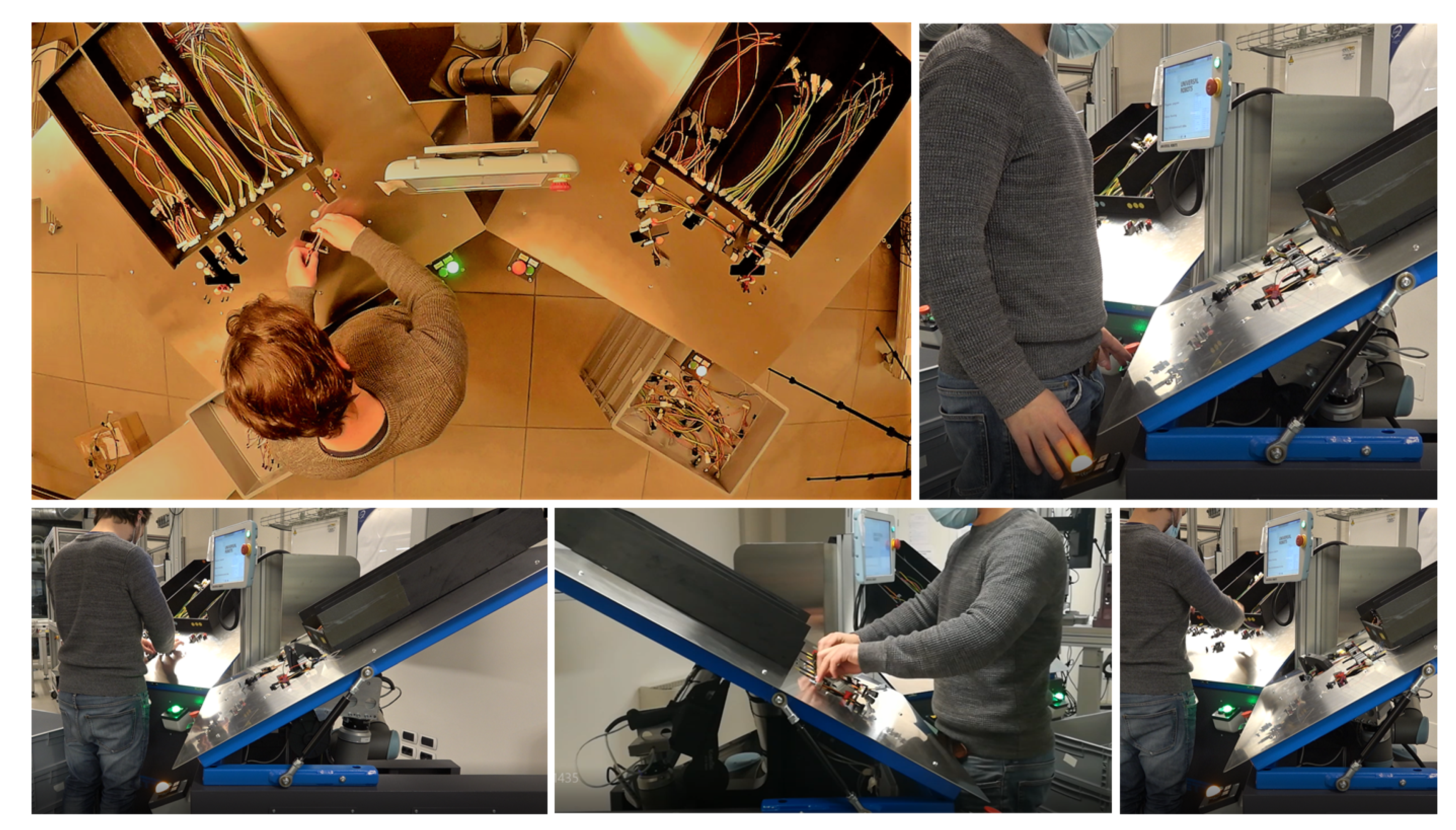
6.2. Improvement of the Operator’s Working Conditions
6.3. Safety Assessment
7. Discussion and Conclusions
- Flexibility. Although the mechanical part of the workstation can already be easily reconfigured to react quickly to product variability, the automatic management of product change from the robot side has not been addressed yet. As future development, the robot will be provided with a vision system and workstation top with markers, so that by means of vision tasks the robot can automatically recognize a new product and adapt its operations.
- Physical ergonomics. Even if a great improvement of the working postures has been obtained, the final RULA score is slightly over the optimal zone (i.e., the green one). To further improve the operator’s physical ergonomics, other methodologies that allow for a more detailed assessment (and hence a better identification) of the biomechanical risks will be adopted, for example the OCRA check list analysis [30].
- Safety. The risk assessment was performed only for mechanical risks related to the operators working with the robot. However, it must be extended to all the workers interacting with the system (e.g., maintainers). The final, industrial version of the product will be manufactured in compliance with all the essential health and safety requirements specified by the Machinery Directive [31].
Author Contributions
Funding
Informed Consent Statement
Data Availability Statement
Conflicts of Interest
References
- Trommnau, J.; Kühnle, J.; Siegert, J.; Inderka, R.; Bauernhansl, T. Overview of the State of the Art in the Production Process of Automotive Wire Harnesses, Current Research and Future Trends. Procedia CIRP 2019, 81, 387–392. [Google Scholar] [CrossRef]
- Trommnau, J.; Frommknecht, A.; Siegert, J.; Wößner, J.; Bauernhansl, T. Design for Automatic Assembly: A new Approach to Classify Limp Components. Procedia CIRP 2020, 91, 49–54. [Google Scholar] [CrossRef]
- Shi, G.M.; Jian, W. Wiring harness assembly detection system based on image processing technology. In Proceedings of the 2011 International Conference on Electronics, Communications and Control, ICECC 2011, Ningbo, China, 9–11 September 2011; pp. 2397–2400. [Google Scholar] [CrossRef]
- Yumbla, F.; Abeyabas, M.; Luong, T.; Yi, J.S.; Moon, H. Preliminary Connector Recognition System Based on Image Processing for Wire Harness Assembly Tasks. In Proceedings of the 2020 20th International Conference on Control, Automation and Systems (ICCAS), Busan, Korea, 13–16 October 2020; pp. 1146–1150. [Google Scholar] [CrossRef]
- Tamada, T.; Yamakawa, Y.; Senoo, T.; Ishikawa, M. High-speed manipulation of cable connector using a high-speed robot hand. In Proceedings of the 2013 IEEE International Conference on Robotics and Biomimetics, ROBIO 2013, Shenzhen, China, 12–14 December 2013; pp. 1598–1604. [Google Scholar] [CrossRef]
- Song, H.C.; Kim, Y.L.; Lee, D.H.; Song, J.B. Electric connector assembly based on vision and impedance control using cable connector-feeding system. J. Mech. Sci. Technol. 2017, 31, 5997–6003. [Google Scholar] [CrossRef]
- Jiang, X.; Nagaoka, Y.; Ishii, K.; Abiko, S.; Tsujita, T.; Uchiyama, M. Robotized recognition of a wire harness utilizing tracing operation. Robot. Comput. Integr. Manuf. 2015, 34, 52–61. [Google Scholar] [CrossRef]
- Koo, K.; Jiang, X.; Konno, A.; Uchiyama, M. Development of a wire harness assembly motion planner for redundant multiple manipulators. J. Robot. Mechatron. 2011, 23, 907–918. [Google Scholar] [CrossRef]
- Guo, J.; Zhang, J.; Wu, D.; Gai, Y.; Chen, K. An algorithm based on bidirectional searching and geometric constrained sampling for automatic manipulation planning in aircraft cable assembly. J. Manuf. Syst. 2020, 57, 158–168. [Google Scholar] [CrossRef]
- Koo, K.M.; Jiang, X.; Kikuchi, K.; Konno, A.; Uchiyama, M. Development of a robot car wiring system. In Proceedings of the IEEE/ASME International Conference on Advanced Intelligent Mechatronics, AIM, Xi’an, China, 2–5 July 2008; pp. 862–867. [Google Scholar] [CrossRef]
- Jiang, X.; Koo, K.; Kikuchi, K.; Konno, A.; Uchiyama, M. Robotized assembly of a wire harness in car production line. In Proceedings of the 2010 IEEE/RSJ International Conference on Intelligent Robots and Systems, Taipei, Taiwan, 18–22 October 2010; pp. 490–495. [Google Scholar] [CrossRef] [Green Version]
- Company Elvez d.o.o. Available online: https://elvez.si/en/ (accessed on 21 December 2020).
- Wire Cobots. Available online: https://www.wirecobots.com/en/ (accessed on 21 December 2020).
- ESMERA. European SMEs Robotic Applications. Available online: http://www.esmera-project.eu (accessed on 21 December 2020).
- Company Carretta s.r.l. Available online: http://www.carrettaautomazioni.it/en/ (accessed on 21 December 2020).
- Gualtieri, L.; Rojas, R.; Carabin, G.; Palomba, I.; Rauch, E.; Vidoni, R.; Matt, D. Advanced Automation for SMEs in the I4.0 Revolution: Engineering Education and Employees Training in the Smart Mini Factory Laboratory. In Proceedings of the IEEE International Conference on Industrial Engineering and Engineering Management, Bangkok, Thailand, 16–19 December 2019; pp. 1111–1115. [Google Scholar] [CrossRef]
- McAtamney, L.; Corlett, N. R.U.L.A.—A Rapid Upper Limb Assessment tool. In Proceedings of the Contemporary Ergonomics 1984–2008: Selected Papers and an Overview of the Ergonomics Society Annual Conference, San Antonio, TX, USA, 19–23 October 2009; pp. 316–321. [Google Scholar]
- ISO/TR 14121-2:2012. Safety of Machinery—Risk Assessment—Part 2: Practical Guidance and Examples of Methods; International Organization for Standardization: Geneva, Switzerland, 2012. [Google Scholar]
- Gualtieri, L.; Palomba, I.; Merati, F.; Rauch, E.; Vidoni, R. Design of Human-Centered Collaborative Assembly Workstations for the Improvement of Operators’ Physical Ergonomics and Production Efficiency: A Case Study. Sustainability 2020, 12, 3606. [Google Scholar] [CrossRef]
- EN ISO 14738:2008. Safety of Machinery—Anthropometric Requirements for the Design of Workstations at Machinery; International Organization for Standardization: Geneva, Switzerland, 2008. [Google Scholar]
- Faccio, M.; Minto, R.; Rosati, G.; Bottin, M. The influence of the product characteristics on human-robot collaboration: A model for the performance of collaborative robotic assembly. Int. J. Adv. Manuf. Technol. 2020, 106, 2317–2331. [Google Scholar] [CrossRef]
- Gualtieri, L.; Palomba, I.; Wehrle, E.; Vidoni, R. The Opportunities and Challenges of SME Manufacturing Automation: Safety and Ergonomics in Human–Robot Collaboration. In Industry 4.0 for SMEs Challenges, Opportunities and Requirements; Matt, D., Modrak, V., Zsifkovits, H., Eds.; Palgrave Macmillan: London, UK, 2020; pp. 105–144. [Google Scholar] [CrossRef] [Green Version]
- Universal Robot. User Manual UR3/CB3 Original Instructions (Version 3.1); Universal Robot: Odense, Denmark, 2009. [Google Scholar]
- Rojas, R.A.; Garcia, M.A.R.; Gualtieri, L.; Wehrle, E.; Rauch, E.; Vidoni, R. Automatic Planning of Psychologically Less-Stressful Trajectories in Collaborative Workstations: An Integrated Toolbox for Unskilled Users. In Symposium on Robot Design, Dynamics and Control; Springer: Berlin/Heidelberg, Germany, 2020; pp. 118–126. [Google Scholar]
- Gualtieri, L.; Rauch, E.; Vidoni, R. Emerging research fields in safety and ergonomics in industrial collaborative robotics: A systematic literature review. Robot. Comput. Integr. Manuf. 2021, 67. [Google Scholar] [CrossRef]
- Murashov, V.; Hearl, F.; Howard, J. Working safely with robot workers: Recommendations for the new workplace. J. Occup. Environ. Hyg. 2016, 13, D61–D71. [Google Scholar] [CrossRef] [PubMed] [Green Version]
- Matthias, B.; Reisinger, T. Example application of ISO/TS 15066 to a collaborative assembly scenario. In Proceedings of the 47th International Symposium on Robotics, ISR 2016, Frankfurt am Main, Germany, 21–22 June 2016; pp. 88–92. [Google Scholar]
- ISO/TS 15066:2016. Robots and Robotic Devices—Collaborative Robots; International Organization for Standardization: Geneva, Switzerland, 2016. [Google Scholar]
- EN ISO 10218-2:2011. Robots and Robotic Devices—Safety Requirements for Industrial Robots—Part 2: Robot Systems and Integration; International Organization for Standardization: Geneva, Switzerland, 2011. [Google Scholar]
- Colombini, D. Risk Assessment and Management of Repetitive Movements and Exertions of Upper Limbs: Job Analysis, Ocra Risk Indices, Prevention Strategies, and Design Principles; Elsevier Ergonomics Book Series; Elsevier: Amsterdam, The Netherlands, 2002; Volume 2. [Google Scholar]
- European Union. Directive 2006/42/EC of the European Parliament and of the Council of 17 May 2006; Machinery Directive, Official Journal of the European Union; European Union: Brussels, Belgium, 2006. [Google Scholar]


| Table C | Neck, Trunk, Leg Scores | |||||||
|---|---|---|---|---|---|---|---|---|
| 1 | 2 | 3 | 4 | 5 | 6 | 7+ | ||
| 1 | 1 | 2 | 3 | 3 | 4 | 5 | 5 | |
| 2 | 2 | 2 | 3 | 4 | 4 | 5 | 5 | |
| Wrist | 3 | 3 | 3 | 3 | 4 | 4 | 5 | 6 |
| and | 4 | 3 | 3 | 3 | 4 | 5 | 6 | 6 |
| arm | 5 | 4 | 4 | 4 | 5 | 6 | 7 | 7 |
| scores | 6 | 4 | 4 | 5 | 6 | 6 | 7 | 7 |
| 7 | 5 | 5 | 6 | 6 | 7 | 7 | 7 | |
| 8+ | 5 | 5 | 6 | 7 | 7 | 7 | 7 | |
| Score meaning: | ||||||||
| 1–2 | Posture acceptable if not maintained or repeated for long period | |||||||
| 3–4 | Further investigation is need, and changes may be required | |||||||
| 5 | Investigation and changes are required soon | |||||||
| 7 | Investigation and changes are required immediately | |||||||
| CI | |||||
|---|---|---|---|---|---|
| Se | 3–4 | 5–7 | 8–10 | 11–13 | 14–15 |
| 4 | |||||
| 3 | |||||
| 2 | |||||
| 1 | |||||
| Body | Body | Manual W.S. | Collaborative W.S. | Score Variation | |||
|---|---|---|---|---|---|---|---|
| Region | Part | Scores | Scores | ||||
| Left Side | Right Side | hLeft Side | Right Side | hLeft Side | Right Side | ||
| Upper arm posture | 4 | 6 | 2 | 2 | −2 | −4 | |
| Arm | Lower arm posture | 3 | 3 | 3 | 3 | 0 | 0 |
| and | Wrist posture | 3 | 4 | 2 | 2 | −1 | −2 |
| wrist | Wrist twist posture | 2 | 2 | 2 | 2 | 0 | 0 |
| analysis | Muscle use | 0 | 0 | 0 | 0 | 0 | 0 |
| Force/load | 0 | 0 | 0 | 0 | 0 | 0 | |
| Neck, | Neck posture | 4 | 3 | −1 | |||
| trunk, | Trunk posture | 4 | 2 | −2 | |||
| and | Leg posture | 1 | 1 | 0 | |||
| leg | Muscle use | 0 | 0 | 0 | |||
| analysis | Force/load | 0 | 0 | 0 | |||
| Final RULA scores | 6 | 7 | 3 | 3 | −3 | −4 | |
| Improvement (percentage reduction of the final W.S. scores) | 50% | 57% | |||||
| Parameter | Prototype NOT | Implementing the SM | Prototype | Implementing the SM | Potential Improvements | |
|---|---|---|---|---|---|---|
| Robot Operating Zone | ||||||
| Mechanical hazard: | 3—Possible | 1—Negligible | −2 | |||
| H1 | 3—Interval between exposure is more than two weeks but less than or equal to a year | 2—Interval between exposure is more than a year | −1 | |||
| 3—Possible | 1—Likely | −2 | ||||
| Safety measures: | 9 | 4 | −5 | |||
| SM1, SM4, SM5, SM6 | 3—Normally irreversible injury—it will be slightly difficult to continue work after healing | 3—Normally irreversible injury—it will be slightly difficult to continue work after healing | None | |||
| Risk level | High | Low | ||||
| Collaborative Operating Zone | ||||||
| Mechanical hazard: | 3—Possible | 2—Rarely | −1 | |||
| H2 | 5—Interval between exposure is more than an hour but less than or equal to a day | 4—Interval between exposure is more than a day but less than or equal to two weeks | −1 | |||
| 1—Likely | 1—Likely | None | ||||
| Safety measures: | 9 | 7 | −2 | |||
| SM2, SM3, SM5, SM6 | 2—More severe scratches, bruises, stabbing, which require medical attention from professionals | 1—Scratches, bruises that are cured by first aid or similar | −1 | |||
| Risk level | Medium | Low | ||||
| Mechanical hazard: | 3—Possible | 1—Negligible | −2 | |||
| H3 | 4—Interval between exposure is more than a day but less than or equal to two weeks | 2—Interval between exposure is more than a year | −1 | |||
| 3—Possible | 1—Likely | −2 | ||||
| Safety measures: | 10 | 4 | −6 | |||
| SM1, SM4, SM5, SM6 | 2—More severe scratches, bruises, stabbing, which require medical attention from professionals | 2—More severe scratches, bruises, stabbing, which require medical attention from professionals | None | |||
| Risk level | High | Low | ||||
Publisher’s Note: MDPI stays neutral with regard to jurisdictional claims in published maps and institutional affiliations. |
© 2021 by the authors. Licensee MDPI, Basel, Switzerland. This article is an open access article distributed under the terms and conditions of the Creative Commons Attribution (CC BY) license (http://creativecommons.org/licenses/by/4.0/).
Share and Cite
Palomba, I.; Gualtieri, L.; Rojas, R.; Rauch, E.; Vidoni, R.; Ghedin, A. Mechatronic Re-Design of a Manual Assembly Workstation into a Collaborative One for Wire Harness Assemblies. Robotics 2021, 10, 43. https://doi.org/10.3390/robotics10010043
Palomba I, Gualtieri L, Rojas R, Rauch E, Vidoni R, Ghedin A. Mechatronic Re-Design of a Manual Assembly Workstation into a Collaborative One for Wire Harness Assemblies. Robotics. 2021; 10(1):43. https://doi.org/10.3390/robotics10010043
Chicago/Turabian StylePalomba, Ilaria, Luca Gualtieri, Rafael Rojas, Erwin Rauch, Renato Vidoni, and Andrea Ghedin. 2021. "Mechatronic Re-Design of a Manual Assembly Workstation into a Collaborative One for Wire Harness Assemblies" Robotics 10, no. 1: 43. https://doi.org/10.3390/robotics10010043