
Projectile Coherence Effects in Twisted Electron Ionization of Helium

Physics Department, Illinois State University, Normal, IL 61790, USA
Atoms 2023, 11(5), 79; https://doi.org/10.3390/atoms11050079
Submission received: 28 February 2023
/
Revised: 25 April 2023
/
Accepted: 26 April 2023
/
Published: 3 May 2023
(This article belongs to the Special Issue Photon and Particle Impact Spectroscopy and Dynamics of Atoms, Molecules, and Clusters)
Abstract
:Over the last decade, it has become clear that for heavy ion projectiles, the projectile’s transverse coherence length must be considered in theoretical models. While traditional scattering theory often assumes that the projectile has an infinite coherence length, many studies have demonstrated that the effect of projectile coherence cannot be ignored, even when the projectile-target interaction is within the perturbative regime. This has led to a surge in studies that examine the effects of the projectile’s coherence length. Heavy-ion collisions are particularly well-suited to this because the projectile’s momentum can be large, leading to a small deBroglie wavelength. In contrast, electron projectiles that have larger deBroglie wavelengths and coherence effects can usually be safely ignored. However, the recent demonstration of sculpted electron wave packets opens the door to studying projectile coherence effects in electron-impact collisions. We report here theoretical triple differential cross-sections (TDCSs) for the electron-impact ionization of helium using Bessel and Laguerre-Gauss projectiles. We show that the projectile’s transverse coherence length affects the shape and magnitude of the TDCSs and that the atomic target’s position within the projectile beam plays a significant role in the probability of ionization. We also demonstrate that projectiles with large coherence lengths result in cross-sections that more closely resemble their fully coherent counterparts.
1. Introduction
In traditional charged particle scattering theory, the incident projectile is typically considered to be delocalized with an infinitely large coherence. However, in the last decade, it has been shown for heavy ion projectiles that a finite projectile coherence length can significantly alter the collision cross-sections and must be considered when comparing theoretical results with experimental data [1,2,3,4,5,6,7,8,9,10]. In these cases, the width of the impinging particle wave packet can be similar in size or smaller than the target width.
For heavy-ion collisions, the effect of the projectile’s finite coherence length went unnoticed for many decades. During this time, experimental measurements were only possible for total or single differential cross-sections, and theoretical models were limited to collisions with small perturbation parameters (ratio of projectile charge to speed). In many cases, the agreement between experiment and theory for less differential cross-sections under small perturbation parameters was quite satisfactory (e.g., [11,12]).
In more recent years, it became possible to perform fully differential cross-section measurements, which opened the door to more rigorous theory tests [11,13,14,15,16,17,18,19]. In some of the initial studies of fully differential cross-sections for the ionization of helium by heavy-ion impact, significant discrepancies were observed between experiment and theory, even at small perturbation parameters where theory was expected to perform well [13,14,20,21,22,23]. Many possible explanations were suggested [16,20,23,24,25,26,27,28,29,30,31], but it was not until the projectile’s coherence properties were considered that a satisfactory explanation was found [1,2,6,7,10]. These experiments demonstrated that projectile coherence cannot be ignored in heavy-ion collisions. Since that time, numerous theoretical and experimental studies have demonstrated the effects of coherence length on collision cross-sections, as well as the ability to control the projectile coherence length [1,2,3,4,5,6,7,10,32,33,34,35,36,37,38,39].
A projectile’s transverse coherence length is proportional to its deBroglie wavelength, which is inversely proportional to projectile momentum [40,41]. Thus, one technique for controlling projectile coherence is through the alteration of the projectile’s momentum. This control can be readily achieved with heavy ion projectiles by changing either the projectile’s energy or ion type (i.e., mass) [1,2,3,4,32].
For electron projectiles, the control of coherence length through momentum is more challenging due to their small mass. Even at high energies, the electron’s wavelength is large, leading to a coherence length that is generally larger than the target width. It is, however, still possible to control an electron projectile’s coherence length through wave packet sculpting. In particular, electron vortex projectiles have been experimentally demonstrated [42,43,44,45], and these sculpted wave packets offer a method to control projectile coherence in electrons. To date, electron vortex projectiles have been demonstrated in the form of Bessel and Airy electrons. These sculpted (or twisted) electron wave packets differ from their traditional plane wave counterparts in several ways. They can have quantized non-zero orbital angular momentum, which, during a collision, can be transferred to the target or ionized electrons [46,47,48,49]. This leads to possible applications for the orientation and rotation control of individual atoms and molecules through electron vortex collisions [50,51,52,53]. Twisted electrons also have non-zero transverse linear momentum, which has been shown to alter the distribution of electrons in ionization collisions [54,55].
Several studies on electron-atom and electron-molecule collision cross-sections have been performed for Bessel projectiles, and they have shown that the use of an electron vortex projectile alters the collision cross-section [9,46,47,48,54,55,56,57,58,59,60,61,62,63,64]. For elastic scattering [58], it was shown that the projectile maintains its vortex properties throughout the collision process. For excitation collisions [47], orbital angular momentum was transferred from the projectile to the target atom, resulting in the alteration of the selection rules. For ionization collisions [46,54,64], it was shown that the orbital angular momentum of the projectile can be transferred to the ionized electron and that the projectile’s momentum uncertainty alters the angular distribution of ejected electrons. For the ionization of helium by electron vortex projectile, it was also shown that the projectile’s transverse momentum could result in the out-of-plane emission of the ejected electron, an outcome that is not possible with plane wave electrons [55]. For the ionization of H2, the angular distribution of ionized electrons was shown to depend on the orbital angular momentum of the projectile [56].
Here, we present theoretical triple differential cross-sections (TDCSs) for the electron-impact ionization of helium using Laguerre-Gauss and Bessel projectiles. We show that the localized nature of the LG projectile causes the binary peak to shift to larger ejected electron angles and enhances the recoil peak. As the projectile becomes less localized, the cross-sections more closely resemble their delocalized counterparts. We also show that the atomic target’s transverse position within the projectile beam can significantly alter the magnitude of the cross-section. Our results demonstrate that LG projectiles can be used to control the coherence length for electron projectiles and that changing the coherence length has observable effects on the collision cross-section.
2. Theory
To calculate the TDCSs, we used the perturbative first Born approximation (FBA) [46,54]. For the projectile energies and scattering geometries used here, this level of approximation contains the relevant physics and captures the qualitative features of the TDCS. Within the FBA, the TDCS is proportional to the square of the transition matrix
with
Here, is the reduced mass of the He+ ion and the ionized electron, is the reduced mass of the projectile and target atom, is the momentum of the incident projectile, is the momentum of the scattered projectile, and is the momentum of the ionized electron. Equation (2) can be written as an integral over all of position space for each of the particles in the collision by inserting complete sets of position states. Cylindrical coordinates are used to represent the projectile wave functions, and spherical coordinates are used for the atomic electron. With this geometry, the projectile momenta can be written in terms of their respective longitudinal and transverse components as and . We consider here the coplanar scattering geometry, in which the incident projectile, final projectile, and ionized electron momentum lie in the same plane. The incident projectile propagates along the Z-axis, and the scattered projectile lies in the x–z plane with its transverse momentum along the positive X-axis.
The initial state wave function is expressed as a product of the incident vortex wave function and the target atom wave function
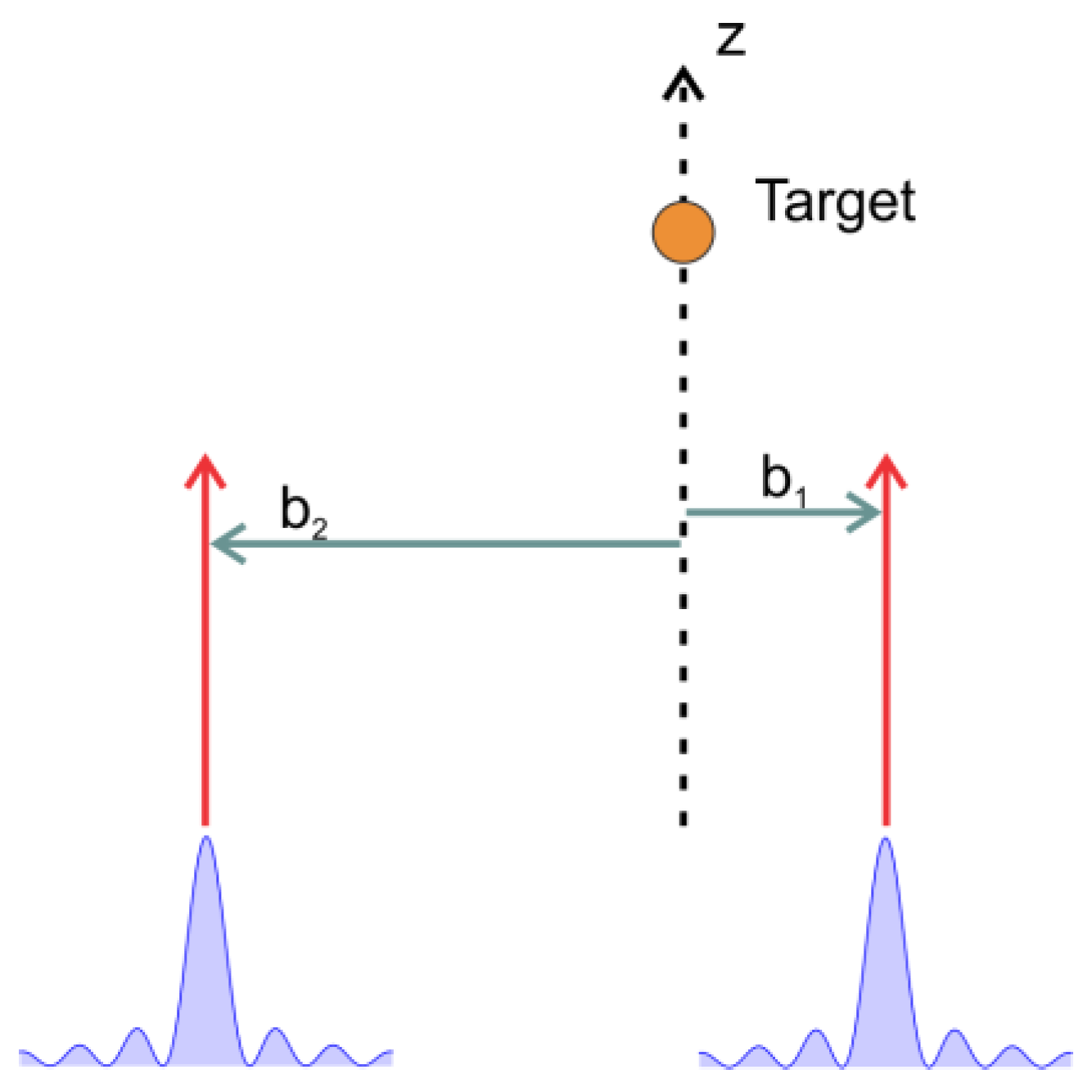
The incident projectile vortex beam may be either a delocalized Bessel beam or a localized Laguerre-Gauss beam. One unique feature of both Bessel and LG vortex beams is that they are non-uniform in the transverse direction with a well-defined center of symmetry. Therefore, their transverse alignment relative to the atomic target must be considered. To account for this alignment, an offset vector (i.e., impact parameter) is introduced such that points transversely from the atomic scattering center to the symmetry center of the impinging vortex projectile (Figure 1).
The wave function for the Bessel projectile with is given by
where is the Bessel function with orbital angular momentum l. This expression can conveniently be rewritten as a superposition of tilted plane waves [58], such that
For an off-center projectile with , the Bessel addition theorem [65] can be used to express the Bessel wave function as
This can, in turn, be expressed in terms of a superposition of plane waves using Equation (5):
The LG beam for is given by [58]:
where is a normalization constant1, is the beam waist, and is an associated Laguerre polynomial with orbital angular momentum l and index n that are related to the number of nodes for a given l. The LG wave function can be written as a convolution of Bessel functions over transverse momentum [58]:
Using Equation (4), the LG wave function can now be expressed as a convolution of Bessel projectile wave functions over transverse momentum:
For an off-center LG projectile, Equation (10) becomes
The transverse coherence of the incident projectile can be defined using quantum mechanical uncertainty:
For Bessel projectiles and plane waves, the transverse uncertainty is infinite, but for LG projectiles, when using Equation (8), it can be shown that the uncertainty is linear with respect to the beam waist:
Some example values of the uncertainty for LG projectiles used here are listed in Table 1. For comparison, the transverse coherence length for atomic helium is a.u.
As is standard for single ionization collisions with fast projectiles [66,67,68,69,70,71,72,73,74], the initial state target helium atom is represented with a single active electron wave function:
where [75,76] is the effective nuclear charge of the 1-electron helium atom and is chosen to give the correct ionization potential of helium.
The final state wave function is a product of the scattered projectile wave function , the ionized electron wave function , and the post-collision Coulomb interaction (PCI) :
We assume that the scattered projectile leaves the collision as a plane wave given by
The perturbation Vi is the Coulomb interaction between the projectile and target atom, which is given by
The ionized electron is modeled as a Coulomb wave:
where is the gamma function and is the Sommerfeld parameter. We note that the use of 1.3443 in and maintains consistency with the treatment of the initial state wave function but does not satisfy asymptotic boundary conditions. This treatment has been used successfully previously for neutral atoms, such as carbon. To be sure that the choice of does not significantly alter the TDCSs, we performed a few calculations with for the perturbation and the Coulomb wave and found nearly identical TDCSs to those with .
The post-collision Coulomb repulsion between the two outgoing final state electrons is included through the use of the Ward-Macek factor [77]:
where
The relative momentum is and the average coordinate , where is the total energy of the two outgoing electrons.
We present the TDCSs for both a fixed impact parameter and an integration of the TDCSs over the impact parameter. The use of a fixed impact parameter allows for the study of projectile-target alignment effects but is not currently experimentally feasible. In a realistic experiment, the projectile’s impact parameter cannot be determined or controlled, and theory must integrate over the impact parameter for an accurate comparison with the experiment. For a Bessel projectile, the TDCS integrated over the impact parameter is given by [46,59]:
where is the transition matrix for an incident plane wave.
For an LG projectile, the TDCS integrated over the impact parameter is given by
3. Results
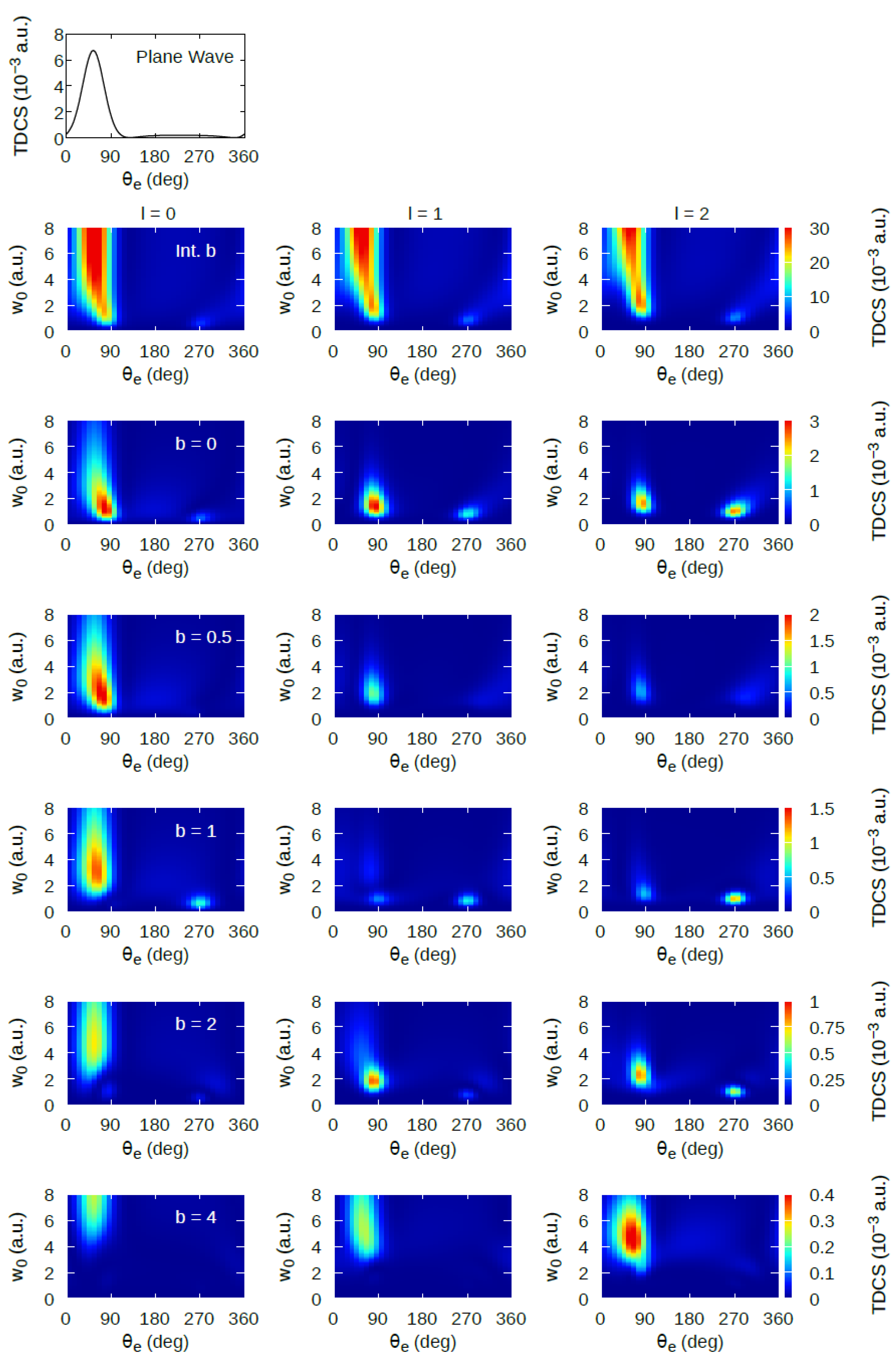
For plane wave projectiles, the shape of the TDCS can largely be explained by classical momentum conservation. There is a large, dominant forward binary peak that results from a single collision between the projectile and the atomic electron. This binary peak is located along the direction of the momentum transfer vector . Directly opposite the binary peak is a smaller recoil peak that results from the atomic electron first undergoing a binary collision with the projectile and then a second deflection by the nucleus that results in backward emission. The top plot in Figure 2 shows the coplanar TDCS as a function of ejected electron angle for a 1 keV plane wave electron colliding with helium. The ionized electron energy was 100 eV, and the scattering angle was 100 mrad (5.7°). These energies and scattering angles ensure that the kinematics are within the applicable range of the FBA. The binary and recoil peaks are clearly visible along and opposite to the momentum transfer vector direction ( 54°).
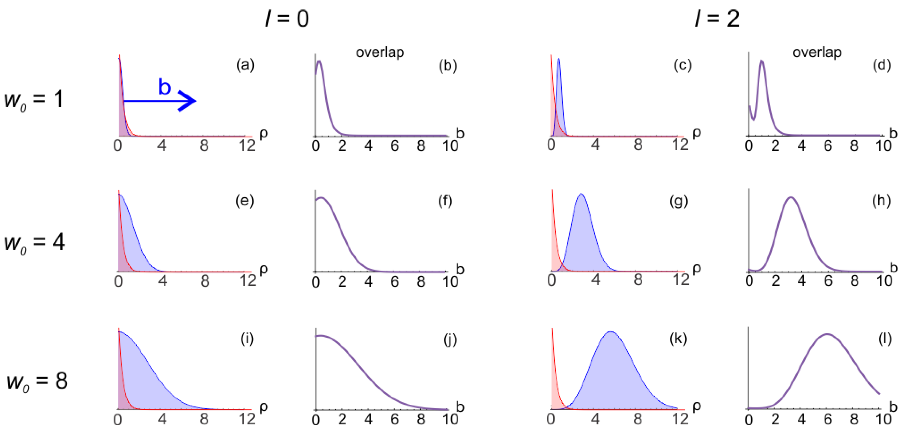
The transverse profiles of the projectile beam and target atomic electron density are shown in Figure 3 for different projectile orbital angular momenta l and beam waists . Note that the projectile profiles are similar to the profiles and, therefore, are not shown in Figure 3. As the impact parameter increases, the relative distance between the center of the projectile beam and the atomic center increases. An increasing impact parameter is depicted in Figure 3 as the projectile beam shifting to the right relative to the atomic center (blue arrow in Figure 3a). Figure 3 shows that the helium target electron density (red) decays exponentially with a maximum density at the nucleus (origin). Figure 3 also shows the normalized overlap between the transverse beam profile and the atomic electron density as a function of impact parameter calculated using
with .
For , the beam profile is Gaussian, and at small values of the beam waist, the overlap between the target electron density and projectile beam is sharply peaked in b. As the beam waist increases, the overlap broadens in b (Figure 3b,f,j). In the case of large , it is expected that the TDCSs will change more slowly with b. It is also expected that for large , the TDCS for an LG projectile will be similar to that of a plane wave since the projectile has become delocalized enough to completely overlap the target out to large radial distances. As the impact parameter increases, the beam profile shifts to the side, and the amount of overlap changes. For a small beam waist, the maximum overlap occurs for an impact parameter of approximately a.u. (Figure 3b). For larger beam waists, the maximum overlap occurs at increasing values of b (Figure 3f,j). Note that for , the maxima of the projectile and target electron densities align for ; however, the overlap is maximum at . This is due to the contribution to the overlap of the tail of the projectile density (only visible on logscale), causing a maximum in the overlap for a finite value of b.
For , the beam profile has a node at the origin, and the width of this node increases with increasing beam waist. Additionally, the width of the beam peak increases with increasing beam waist (Figure 3c,g,k). For on-center collisions, the largest overlap of the beam and the atomic electron density occurs for a small beam waist (Figure 3c). As the beam waist increases, the central node becomes wider, and the overlap with the target electron density decreases. For off-center collisions, as the impact parameter increases, the overlap increases to a maximum value before decreasing at large b (Figure 3h,l). The value of b for which the overlap is maximum depends on the specific value of the beam waist but occurs near the radial distance where the LG beam density is maximum.
3.1. LG Projectiles with Zero Orbital Angular Momentum
In rows two through seven in Figure 2, we present the TDCSs for LG projectiles with different beam waists, impact parameters, and orbital angular momenta. We note that the results for are qualitatively similar to those with and are not shown here. In Figure 2, the TDCS magnitude is presented in color, with the warmer colors representing larger TDCS values. The vertical axis in each panel shows the beam waist, while the horizontal axis depicts the ejected electron angle. The second row shows TDCSs integrated over the impact parameter, while rows three–seven show the TDCSs for a fixed impact parameter (labeled in the left column). For the TDCSs with a fixed impact parameter, we assume that the projectile center is shifted by a distance of b along the negative x-axis (i.e., ), and note that the TDCSs calculated for were identical to those for . For the TDCSs integrated over , all radial values and azimuthal angles were included in the integration. Each column shows the TDCSs for a different orbital angular momentum (labeled above row two).
Consider first the on-center and zero orbital angular momentum TDCSs (third row, first column in Figure 2). In this case, the beam has a Gaussian transverse profile with no nodes. The largest cross-section occurs with a beam waist of , with the binary peak located at an ejected electron angle of 85°. As the beam waist increases, the binary peak location shifts to smaller angles until it is located at the plane wave momentum transfer direction of 54°. This indicates that for a large beam waist, the TDCS more closely resembles that of the plane wave TDCS, as predicted from the complete overlap between the beam and target electron density. The shift of the binary peak from the momentum transfer direction for small beam waists could be caused by two factors—the PCI between the outgoing electrons or the projectile’s non-zero transverse momentum. Given the large relative momentum between the two outgoing electrons, it is unlikely that the shift in binary peak location is due to the PCI, and a calculation that does not include PCI (not shown) confirmed this expectation. Therefore, we conclude that the shift in binary peak location is due to the transverse momentum of the projectile. Additional details are provided in Section 3.5.
For off-center collisions and zero angular momentum (rows four–seven, column one in Figure 2), the maximum TDCS occurs with increasing beam waist as the impact parameter increases. For , the TDCS only becomes observable in the colormap plots for when the overlap between the beam profile and target electron density is non-negligible. Because the TDCS with a large impact parameter is observable only when the beam waist is large, the coherence length of the projectile is also necessarily large. This leads to a more plane wave-like TDCS shape, with the binary peak located at the momentum transfer direction. As the impact parameter increases, the overall magnitude of the TDCS decreases (see changing color scale for different rows), indicating that ionization becomes less likely for larger impact parameters. This correlates with the amount of overlap between the projectile and target electron density. Regardless of beam waist, the overlap decreases with increasing impact parameters (see Figure 3b,f,j).
For most values of and , there is almost no recoil peak observable, indicating that rescattering by the nucleus is unlikely. This is primarily due to the energy of the ejected electron, which is fast enough to not experience much Coulomb pull from the nucleus. The notable exception is for and small beam waists, in which case the recoil peak is larger than the binary peak. This corresponds to a narrow projectile beam impinging on the target. For a small beam waist, there is a maximum in the overlap near to 1.5 a.u., which corresponds with the kinematical conditions that yield an enhanced recoil peak.
For the TDCSs integrated over , a strong binary peak is observed for nearly all . At the smallest beam waist values ( a.u.), the binary peak is very small and virtually invisible on the scale used in Figure 2. As the beam waist increases, a narrow binary peak is visible near . This binary peak broadens and shifts to approximately the plane wave binary peak location for a.u. For a beam waist greater than 4 a.u., the transverse coherence length of the projectile is equal to or larger than that of the target atom. Therefore, the incident projectile wave packet fully overlaps the target, and coherent emission of the ionized electron occurs, as in the case of a plane wave or Bessel wave. This leads to the TDCSs for LG projectiles with large transverse coherence resembling the TDCSs of the plane wave and Bessel projectiles.
3.2. LG Projectiles with Non-Zero Orbital Angular Momentum
For on-center collisions with non-zero orbital angular momentum (row three, columns two and three in Figure 2), the binary and recoil peaks are more similar in magnitude, and both peaks are more localized to small beam waists. This is consistent with conditions for maximum overlap between the projectile density and the atomic electron density. For a large beam waist, the node in the center of the projectile density results in very little overlap between the projectile and the target electron density, resulting in very small TDCSs.
For small beam waists, the binary and recoil peaks are located at approximately 90° and 270°, which is shifted from the classical momentum transfer directions. We have previously shown that for delocalized Bessel beam projectiles, the influence of the transverse momentum of the projectile alters the angular distribution of the TDCS [46,54]. Because the TDCS for a Bessel beam was represented as a superposition over tilted plane waves, the TDCS resulting from the smallest momentum transfer dominated the sum. This determined the location of the binary and recoil peaks, which were shifted to approximately 90° and 270°. For LG beams, the transition matrix is a convolution over Bessel transition matrices, and therefore the same effect is present here, but with some averaging of location, as discussed in Section 3.5.
As the beam waist increases, the recoil peak decreases in magnitude more rapidly than the binary peak. This is due to the projectile probing the outer part of the target electron wave function, where the influence of the nucleus is reduced. For , the binary and recoil peak magnitudes are more similar than for , indicating that larger projectile orbital angular momentum results in more secondary scattering from the nucleus and, thus, a larger recoil peak. As was the case for collisions with zero orbital angular momentum, for off-center collisions with non-zero orbital angular momentum, the magnitude of the cross-sections decreases with increasing impact parameter.
The TDCSs averaged over the impact parameter for non-zero orbital angular momentum show similar qualitative features to those with zero orbital angular momentum. The width of the binary peak remains narrow for larger beam waists as orbital angular momentum increases, despite the fact that the transverse coherence length is larger for larger values of orbital angular momentum. This indicates that while transverse coherence length alters the magnitude and binary peak locations of TDCSs, it is not the only factor. Orbital angular momentum also plays a role in the ejected electron distribution.
3.3. Bessel Projectiles with Zero Orbital Angular Momentum
LG projectiles differ from their plane wave counterparts not just in their localization but in their ability to carry quantized orbital angular momentum. For , a comparison of TDCSs for LG projectiles with Bessel projectiles can more reasonably isolate localization effects because the LG and Bessel projectiles can carry the same orbital angular momentum. Unlike the localized LG projectiles, Bessel projectiles have infinite transverse extent, and the beam waist parameter does not exist. Comparison of TDCSs for LG and Bessel projectiles allows for the study of coherence effects between projectiles with the same orbital angular momentum.
Bessel projectiles are characterized by their orbital angular momentum l and their opening angle , which is related to the incident transverse momentum by
As the opening angle increases, the transverse momentum increases and the peaks in the density become narrower. For and , the Bessel projectile is identical to a plane wave.
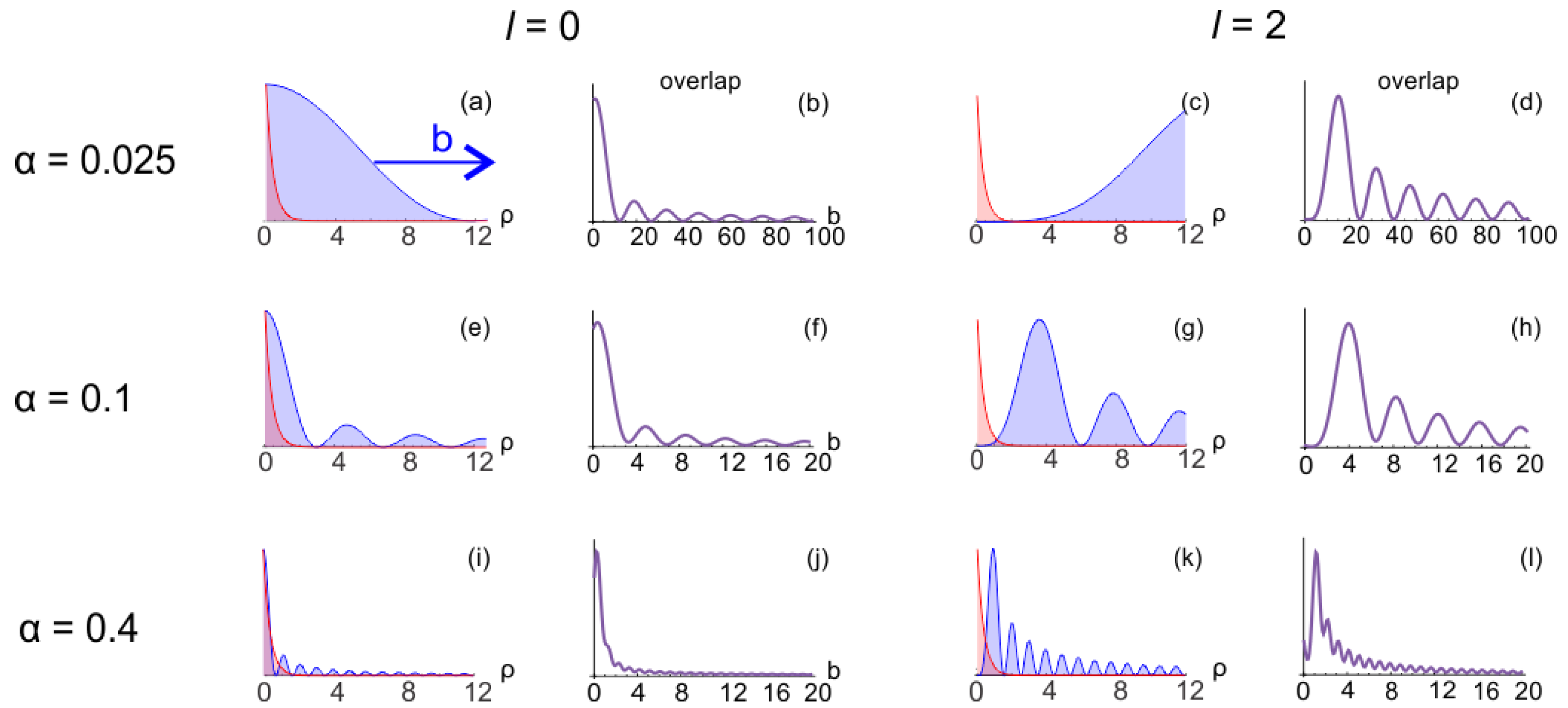
In Figure 4, we plot the normalized transverse projectile density for Bessel projectiles (blue) and the target electron (red). Also shown is the normalized overlap between the projectile and target electron density as a function of impact parameter. As with LG projectiles, the overlap between the Bessel projectile and the target atom varies significantly as orbital angular momentum and opening angle change. In general, the transverse profile of the Bessel projectile has a series of decreasing peaks as the transverse distance increases. For , there is a single peak at the center of the beam, but for , there is a node. Unlike the localized LG projectile, the overlap between the Bessel projectile and the target electron density can be significantly non-zero for large values of the impact parameter. This is most notable for small opening angles, where the overlap is appreciable beyond (Figure 4b,d).
For zero orbital angular momentum, Figure 4 shows that for small opening angles, the central peak is quite broad and the overlap between the beam and the target is large. In this case, the TDCSs are expected to resemble those of the plane wave and the LG projectile with large beam waist. As the impact parameter increases, the overlap between the target and the beam decreases until one of the nodes of the Bessel beam overlaps significantly with the target electron density, creating a minimum in the overlap. The overlap then increases again as the next lobe in the Bessel wave function overlaps the target density, creating a peak in the overlap. For each side lobe of the Bessel wave function that overlaps the target density, an additional peak structure is present in the overlap (Figure 4b).
As the opening angle increases, the central peak of the Bessel beam narrows and the overlap with the target electron density decreases. For larger values of , as the impact parameter increases, the peak structures observed in the overlap are less pronounced (Figure 4j). The overlap function for most closely resembles that of the LG projectile with , and thus the TDCSs for these parameters are expected to be similar.
For non-zero orbital angular momentum, the node at the center of the projectile density is largest for small opening angles (Figure 4c). This results in nearly zero overlap between the target electron density and the projectile for on-center collisions with small opening angles. As the impact parameter increases for small , a series of peak structures are observed in the overlap, each corresponding to a side lobe of the Bessel projectile overlapping the target (Figure 4d).
As opening angle increases, the width of the central node decreases and the overlap between projectile and target electron density increases for on-center collisions. At the largest opening angle shown in Figure 4k,l, the largest overlap is observed for collisions with a small impact parameter, contrary to what is present for small opening angles. For large opening angles, as the impact parameter increases, the overlap decreases more rapidly than for small opening angles (Figure 4l). In general, for , the overlap for Bessel projectiles with large opening angles most closely resembles that of LG projectiles with small beam waists and the TDCSs for these parameters are expected to be similar. As was the case with LG projectiles, the overlap is crucial to interpreting the structures observed in the TDCSs for Bessel projectiles.
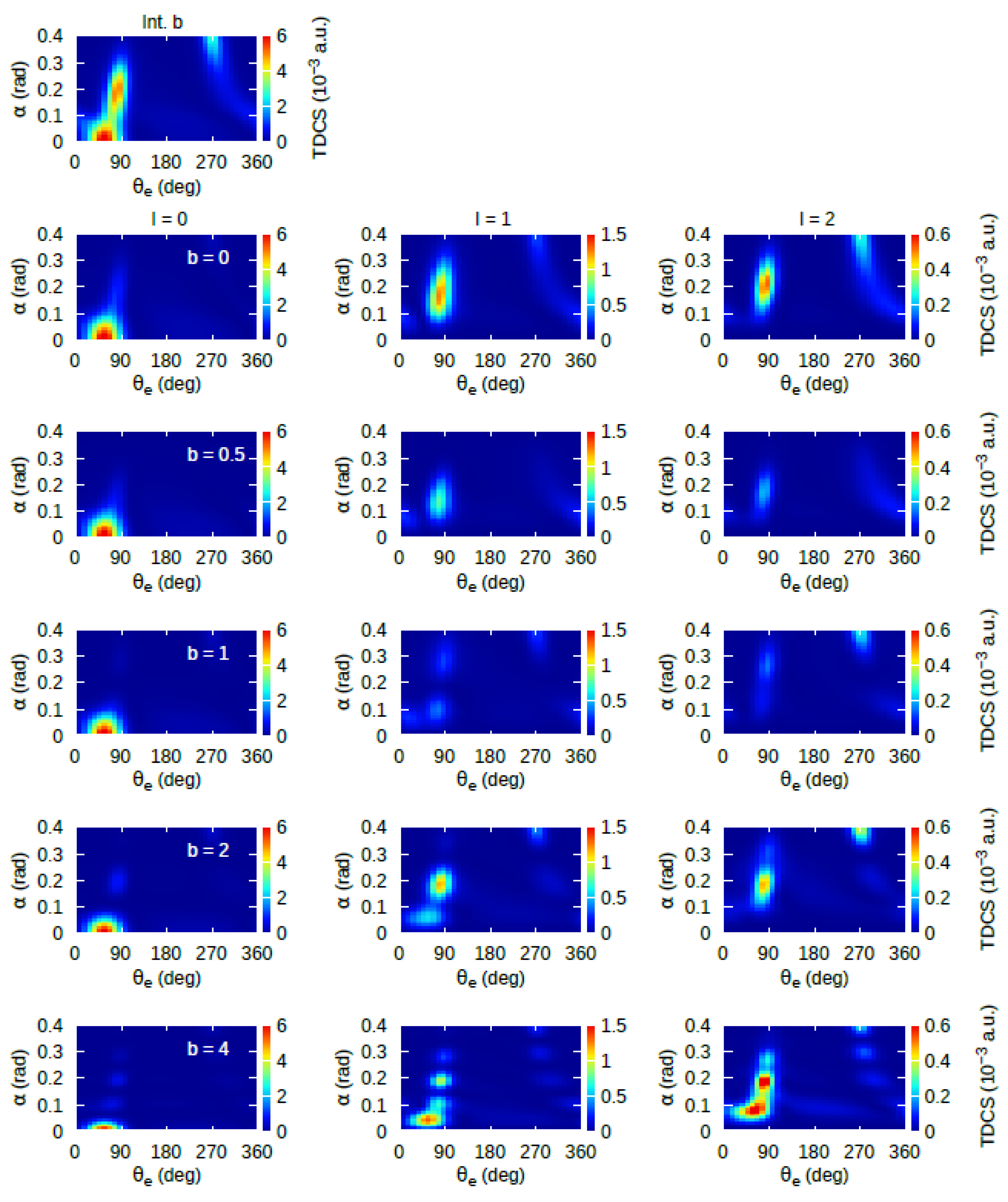
Figure 5 shows the TDCSs for the ionization of helium by Bessel projectiles as a function of the opening angle and ejected electron angle. Similar to Figure 2, row one shows the TDCS integrated over impact parameter. For Bessel projectiles, the integration over impact parameter washes out any dependence on orbital angular momentum, and the TDCS is independent of l. Rows two–six show the TDCSs for a fixed impact parameter (labeled in the left column), and each column shows results for a different orbital angular momentum (labeled above row two).
Consider first the on-center and zero orbital angular momentum TDCSs (first row, first column in Figure 5). In this case, there is a central lobe in the projectile density (Figure 4a,e,i). The TDCSs are largest for small opening angles and closely resemble those of the plane wave (Figure 2). There is a dominant peak located at the momentum transfer direction and no noticeable recoil peak. As the opening angle increases, the cross-sections drop in magnitude due to the reduced overlap between the projectile and target electron density. For off-center collisions (rows three–six, column one in Figure 5), as the impact parameter increases, there is not much change in the TDCS shape or magnitude. For and , the Bessel wave function is identical to a plane wave, and, therefore, the TDCSs at a small opening angle with closely mirror the TDCSs for a plane wave projectile, regardless of impact parameter. This results in the binary peak at the momentum transfer direction that is observed in the TDCSs at small for fixed impact parameters in Figure 5. As the impact parameter increases, the TDCS drops off more quickly with increasing opening angle, which is again consistent with the decreased overlap between the projectile and target atom densities.
3.4. Bessel Projectiles with Non-Zero Orbital Angular Momentum
For the on-center projectiles with non-zero orbital angular momentum (row two, columns two and three in Figure 5), the peaks in the TDCS occur at larger values of and, in some cases, a small recoil peak is present. This is directly related to the overlap between the projectile and target electron density. For the Bessel projectiles with , there is a node at the center of the projectile density. For small values, this node is quite large, and there is almost no overlap between the projectile and target electron density. It is only for rad that some overlap occurs. For even larger values of , the TDCS again decreases in magnitude as the nodes become narrower and the overlap decreases. For both and , there is a small binary peak present for rad. This binary peak shifts to larger ejected electron angles and increases in magnitude as the opening angle increases. This effect was observed in some of our previous calculations for the ionization of hydrogen by Bessel projectile and was traced to the transverse momentum component of the incident projectile [54]. At a large opening angle, a recoil peak is present, and its location moves to smaller ejected electron angles as the opening angle increases. The shift in recoil peak location with increasing opening angle can also be traced to the transverse momentum of the incident projectile. In fact, as we showed in [54], at very large values of , the dominant momentum transfer direction occurs at , and what appears to be the recoil peak is, in reality, the binary peak. Thus, the observed TDCS peak at for a large is, in fact, the binary peak.
As the impact parameter increases, the magnitude of the TDCS decreases, and very few features are observable in the color plots for or 1 a.u. As the impact parameter increases beyond 1 a.u., the side lobes of the Bessel projectile, again, overlap with the target electron density, resulting in clearly observable binary peak structures. At the largest impact parameter of a.u., oscillations are observed in the binary peak magnitude as the opening angle increases. These are a direct result of the side lobes of the Bessel projectile overlapping the target electron. Each peak in the TDCS corresponds to one of the Bessel lobes overlapping the target. As the opening angle increases, the location of the binary peak shifts to larger ejected electron angles. This can, again, be traced to the projectile’s transverse momentum, which increases with the opening angle. As the projectile’s transverse momentum increases, the location of the classically predicted momentum transfer direction changes, which shifts the location of the binary peak. Recoil peak structures are observed again at large opening angles for non-zero impact parameters, and at a.u., oscillations are observed in the recoil peak magnitude as the opening angle increases. As was the case with the binary peak magnitude oscillations, the recoil peak oscillations are due to the Bessel wave function side lobes. Additionally, as was the case for , the recoil peak observed for a.u. is, in reality, the binary peak.
The TDCSs integrated over the impact parameter show a forward binary peak at the plane wave momentum transfer direction, which then shifts to larger ejected electron angles as the opening angle increases. Because the TDCSs integrated over the impact parameter include contributions from all impact parameters and orbital angular momentum values, some of the features can be traced to TDCS contributions from specific impact parameters or orbital angular momentum values. For example, the binary peak at small at the plane wave momentum transfer direction is predominantly caused by the TDCSs, while the binary peak at larger values is a result of the TDCSs for projectiles with non-zero l. The enhanced recoil peak at the largest opening angles also results from TDCSs of projectiles with non-zero orbital angular momentum.
3.5. Relation of LG to Bessel Projectiles
As Equation (11) shows, the LG projectile can be written as a convolution over the transverse momentum, with each Bessel wave function weighted by the factor
For large values of the beam waist, this weighting factor becomes more localized in at smaller values of the transverse momentum. This results in the convolution favoring a few Bessel wave functions with small transverse momenta (i.e., small ). Because these are the Bessel wave functions that most resemble the plane wave function, the resulting LG projectile is delocalized in space with a large coherence length. In other words, the highly localized weighting factor of Equation (25) in transverse momentum space results in a delocalized wave function in position space. This weighting results in the TDCSs for LG projectiles with large beam waists being a sort of average over the Bessel TDCSs for small . Therefore, the LG TDCSs at large resemble those of the Bessel projectile at small opening angles with a strong binary peak and negligible recoil peak.
For small values of the beam waist, the weighting factor in Equation (25) is a broader function of and centered at larger values of transverse momentum. This results in many Bessel wave functions with large transverse momenta contributing to the convolution. In this case, the broad weighting factor of Equation (25) in transverse momentum space results in a localized wave function in position space. Thus, the LG TDCSs at small are similar to an average over the Bessel TDCSs at large with approximately equal magnitude binary and recoil peaks.
4. Summary
We have presented TDCSs for the ionization of helium by LG and Bessel electron projectiles. A comparison of the localized LG TDCSs and the fully coherent, delocalized Bessel TDCSs provides insight into the role of projectile coherence. This allowed for the direct study of coherence effects independent of orbital angular momentum, which is not possible if plane wave projectiles are used. For LG projectiles, we examined the effects of transverse coherence length, orbital angular momentum, and the impact parameter on the TDCSs. The transverse coherence length was altered by changing the projectile beam waist. For localized projectiles with a small coherence length, the location of the binary peak was shifted to larger ejected electron angles from the classical momentum transfer direction. Additionally, a small recoil peak was observed. As the coherence length increased, the recoil peak magnitude decreased, and the location of the binary peak shifted to the classical momentum transfer direction. At a large coherence length, the TDCSs resembled that of the plane wave and Bessel TDCSs for a completely delocalized projectile. A comparison of the TDCSs for the LG and Bessel projectiles with non-zero orbital angular momentum showed that a localized projectile resulted in an enhanced recoil peak, which was most pronounced for larger orbital angular momentum values. These features were traced to the projectile’s transverse momentum and the different contributions of the Bessel wave functions that result from writing the LG wave function as a convolution over transverse momentum.
The overlap between the projectile’s transverse density and the target electron’s density correlated with the magnitude of the TDCSs. For a large overlap, a large TDCS was observed. The impact parameter, beam waist, and orbital angular momentum all affected the overlap and, correspondingly, the conditions that resulted in large cross-sections. In general, a large cross-section was observed when the projectile’s maximum density aligned with the target electron’s maximum density.
For Bessel projectiles, the location and magnitude of the binary and recoil peaks were dependent upon the opening angle of the incident projectile momentum. As the opening angle increased, the binary peak shifted to larger ejected electron angles, while the recoil peak shifted to smaller angles. This was expected from previous studies on ionization by Bessel projectiles and had been shown to result from the projectile’s transverse momentum. By writing the LG wave function as a convolution of the Bessel wave functions over the transverse momentum, we showed that the features of the Bessel TDCSs contributed to the shape of the LG TDCSs. In particular, at a small coherence length, many Bessel wave functions with large transverse momentum contribute, resulting in an enhanced recoil peak for LG projectiles. In contrast, for a large coherence length, only a few Bessel wave functions with small transverse momentum contribute, and the LG TDCSs resembled the plane wave TDCS.
Overall, our results demonstrate that coherence length can be controlled for electron projectiles through the use of sculpted wave packets and that the shape and magnitude of the TDCSs depend on the projectile coherence length. A comparison of TDCSs for Bessel and LG projectiles isolated the effects of coherence from orbital angular momentum and demonstrated that coherence effects persist regardless of l. We anticipate that these results may open the door to future studies on projectile coherence effects using sculpted electrons, in particular for molecular targets where the interference effects are strongly dependent upon projectile coherence.
Funding
This research was funded by the National Science Foundation grant number PHY-1912093. As an invited article, the APC was waived.
Data Availability Statement
The data presented in this study are available on request from the corresponding author.
Acknowledgments
We gratefully acknowledge the support of the National Science Foundation under Grant No. PHY-1912093.
Conflicts of Interest
The authors declare no conflict of interest.
| 1 | The expression for N in [58] is slightly incorrect. We have calculated N numerically to ensure normalization of the LG wave function. |
References
- Egodapitiya, K.N.; Sharma, S.; Hasan, A.; Laforge, A.C.; Madison, D.H.; Moshammer, R.; Schulz, M. Manipulating Atomic Fragmentation Processes by Controlling the Projectile Coherence. Phys. Rev. Lett. 2011, 106, 153202. [Google Scholar] [CrossRef]
- Sharma, S.; Hasan, A.; Egodapitiya, K.N.; Arthanayaka, T.P.; Sakhelashvili, G.; Schulz, M. Projectile Coherence Effects in Electron Capture by Protons Colliding with H2 and He. Phys. Rev. A 2012, 86, 022706. [Google Scholar] [CrossRef]
- Schneider, K.; Schulz, M.; Wang, X.; Kelkar, A.; Grieser, M.; Krantz, C.; Ullrich, J.; Moshammer, R.; Fischer, D. Role of Projectile Coherence in Close Heavy Ion-Atom Collisions. Phys. Rev. Lett. 2013, 110, 113201. [Google Scholar] [CrossRef] [PubMed]
- Sharma, S.; Arthanayaka, T.P.; Hasan, A.; Lamichhane, B.R.; Remolina, J.; Smith, A.; Schulz, M. Fully Differential Study of Interference Effects in the Ionization of H2 by Proton Impact. Phys. Rev. A 2014, 90, 052710. [Google Scholar] [CrossRef]
- Járai-Szabó, F.; Nagy, L. Theoretical investigations on the projectile coherence effects in fully differential ionization cross sections. Eur. Phys. J. D 2015, 69, 4. [Google Scholar] [CrossRef]
- Sarkadi, L.; Fabre, I.; Navarrete, F.; Barrachina, R.O. Loss of wave-packet coherence in ion-atom collisions. Phys. Rev. A 2016, 93, 032702. [Google Scholar] [CrossRef]
- Navarrete, F.; Ciappina, M.F.; Sarkadi, L.; Barrachina, R.O. The Role of the Wave Packet Coherence on the Ionization Cross Section of He by P+ and C6+ Projectiles. Nucl. Instrum. Methods Phys. Res. Sect. B Beam Interact. Mater. At. 2017, 408, 165. [Google Scholar] [CrossRef]
- Kouzakov, K.A. Theoretical analysis of the projectile and target coherence in COLTRIMS experiments on atomic ionization by fast ions. Eur. Phys. J. D 2017, 71, 63. [Google Scholar] [CrossRef]
- Karlovets, D.V.; Kotkin, G.L.; Serbo, V.G. Scattering of wave packets on atoms in the Born approximation. Phys. Rev. A 2015, 92, 052703. [Google Scholar] [CrossRef]
- Wang, X.; Schneider, K.; LaForge, A.; Kelkar, A.; Grieser, M.; Moshammer, R.; Ullrich, J.; Schulz, M.; Fischer, D. Projectile coherence effects in single ionization of helium. J. Phys. B At. Mol. Opt. Phys. 2012, 45, 211001. [Google Scholar] [CrossRef]
- Gassert, H.; Chuluunbaatar, O.; Waitz, M.; Trinter, F.; Kim, H.-K.; Bauer, T.; Laucke, A.; Müller, C.; Voigtsberger, J.; Weller, M.; et al. Agreement of Experiment and Theory on the Single Ionization of Helium by Fast Proton Impact. Phys. Rev. Lett. 2016, 116, 073201. [Google Scholar] [CrossRef]
- Moshammer, R.; Fainstein, P.D.; Schulz, M.; Schmitt, W.; Kollmus, H.; Mann, R.; Hagmann, S.; Ullrich, J. Initial State Dependence of Low-Energy Electron Emission in Fast Ion Atom Collisions. Phys. Rev. Lett. 1999, 83, 4721. [Google Scholar] [CrossRef]
- Schulz, M.; Moshammer, R.; Fischer, D.; Kollmus, H.; Madison, D.H.; Jones, S.; Ullrich, J. Three-dimensional imaging of atomic four-body processes. Nature 2003, 422, 6927. [Google Scholar] [CrossRef] [PubMed]
- Maydanyuk, N.V.; Hasan, A.; Foster, M.; Tooke, B.; Nanni, E.; Madison, D.H.; Schulz, M. Projectile–Residual-Target-Ion Scattering after Single Ionization of Helium by Slow Proton Impact. Phys. Rev. Lett. 2005, 94, 243201. [Google Scholar] [CrossRef]
- Dörner, R.; Mergel, V.; Ali, R.; Buck, U.; Cocke, C.L.; Froschauer, K.; Jagutzki, O.; Lencinas, S.; Meyerhof, W.E.; Nüttgens, S.; et al. Electron-electron interaction in projectile ionization investigated by high resolution recoil ion momentum spectroscopy. Phys. Rev. Lett. 1994, 72, 3166. [Google Scholar] [CrossRef] [PubMed]
- Madison, D.H.; Fischer, D.; Foster, M.; Schulz, M.; Moshammer, R.; Jones, S.; Ullrich, J. Probing Scattering Wave Functions Close to the Nucleus. Phys. Rev. Lett. 2003, 91, 253201. [Google Scholar] [CrossRef]
- Schulz, M.; Moshammer, R.; Perumal, A.N.; Ullrich, J. Triply Differential Single-Ionization Cross Sections in Fast Ion-Atom Collisions at Large Perturbation. J. Phys. B At. Mol. Opt. Phys. 2002, 35, L161. [Google Scholar] [CrossRef]
- Fischer, D.; Moshammer, R.; Schulz, M.; Voitkiv, A.; Ullrich, J. Fully differential cross sections for the single ionization of helium by ion impact. J. Phys. B At. Mol. Opt. Phys. 2003, 36, 3555. [Google Scholar] [CrossRef]
- Moshammer, R.; Unverzagt, M.; Schmitt, W.; Ullrich, J.; Schmidt-Böcking, H. A 4π Recoil-Ion Electron Momentum Analyzer: A High-Resolution “Microscope” for the Investigation of the Dynamics of Atomic, Molecular and Nuclear Reactions. Nucl. Instrum. Methods Phys. Res. Sect. B Beam Interact. Mater. At. 1996, 108, 425. [Google Scholar] [CrossRef]
- McGovern, M.; Whelan, C.T.; Walters, H.R.J. C6+-Impact Ionization of Helium in the Perpendicular Plane: Ionization to the Ground State, Excitation-Ionization, and Relativistic Effects. Phys. Rev. A 2010, 82, 032702. [Google Scholar] [CrossRef]
- Pedlow, R.T.; O’Rourke, S.F.C.; Crothers, D.S.F. Fully differential cross sections for 3.6 MeV u−1 AuZP+ + He collisions. Phys. Rev. A 2005, 72, 062719. [Google Scholar] [CrossRef]
- Voitkiv, A.B.; Najjari, B. Projectile-Target Core Interaction in Single Ionization of Helium by 100-MeV/u C6+ and 1-GeV/u U92+ Ions. Phys. Rev. A 2009, 79, 022709. [Google Scholar] [CrossRef]
- Fiol, J.; Otranto, S.; Olson, R.E. Critical comparison between theory and experiment for C6+ + He fully differential ionization cross sections. J. Phys. B At. Mol. Opt. Phys. 2006, 39, L285. [Google Scholar] [CrossRef]
- Harris, A.L.; Madison, D.H.; Peacher, J.L.; Foster, M.; Bartschat, K.; Saha, H.P. Effects of the final-state electron-ion interactions on the fully differential cross sections for heavy-particle-impact ionization of helium. Phys. Rev. A 2007, 75, 032718. [Google Scholar] [CrossRef]
- Schulz, M.; Dürr, M.; Najjari, B.; Moshammer, R.; Ullrich, J. Reconciliation of measured fully differential single ionization data with the first Born approximation convoluted with elastic scattering. Phys. Rev. A 2007, 76, 032712. [Google Scholar] [CrossRef]
- Dürr, M.; Najjari, B.; Schulz, M.; Dorn, A.; Moshammer, R.; Voitkiv, A.B.; Ullrich, J. Analysis of experimental data for ion-impact single ionization of helium with Monte Carlo event generators based on quantum theory. Phys. Rev. A 2007, 75, 062708. [Google Scholar] [CrossRef]
- Sharma, S.; Arthanayaka, T.P.; Hasan, A.; Lamichhane, B.R.; Remolina, J.; Smith, A.; Schulz, M. Complete Momentum Balance in Ionization of H2 by 75-KeV-Proton Impact for Varying Projectile Coherence. Phys. Rev. A 2014, 89, 052703. [Google Scholar] [CrossRef]
- Feagin, J.M.; Hargreaves, L. Loss of wave-packet coherence in stationary scattering experiments. Phys. Rev. A 2013, 88, 032705. [Google Scholar] [CrossRef]
- Olson, R.E.; Fiol, J. Dynamics underlying fully differential cross sections for fast C6++He collisions. J. Phys. B At. Mol. Opt. Phys. 2003, 36, L365. [Google Scholar] [CrossRef]
- Járai-Szabó, F.; Nagy, L. Semiclassical description of kinematically complete experiments. J. Phys. B At. Mol. Opt. Phys. 2007, 40, 4259. [Google Scholar] [CrossRef]
- Colgan, J.; Pindzola, M.S.; Robicheaux, F.; Ciappina, M.F. Fully differential cross sections for the single ionization of He by C6+ ions. J. Phys. B At. Mol. Opt. Phys. 2011, 44, 175205. [Google Scholar] [CrossRef]
- Schulz, M.; Hasan, A.; Lamichhane, B.; Arthanayaka, T.; Dhital, M.; Bastola, S.; Nagy, L.; Borbély, S.; Járai-Szabó, F. Projectile Coherence Effects in Simple Atomic Systems. J. Phys. Conf. Ser. 2020, 1412, 062007. [Google Scholar] [CrossRef]
- Gulyás, L.; Egri, S.; Igarashi, A. Theoretical investigation of the fully differential cross sections for single ionization of He in collisions with 75-keV protons. Phys. Rev. A 2019, 99, 032704. [Google Scholar] [CrossRef]
- Navarrete, F.; Ciappina, M.F.; Barrachina, R.O. Coherence properties of the projectile’s beam: The missing piece of the C6+ + He ionization puzzle. J. Physics Conf. Ser. 2020, 1412, 152033. [Google Scholar] [CrossRef]
- Barrachina, R.O.; Navarrete, F.; Ciappina, M.F. Atomic Concealment Due to Loss of Coherence of the Incident Beam of Projectiles in Collision Processes. Atoms 2021, 9, 5. [Google Scholar] [CrossRef]
- Voss, T.; Lamichhane, B.R.; Dhital, M.; Lomsadze, R.; Schulz, M. Differential Study of Projectile Coherence Effects on Double Capture Processes in p + Ar Collisions. Atoms 2020, 8, 10. [Google Scholar] [CrossRef]
- Navarrete, F.; Barrachina, R.; Ciappina, M.F. Distortion of the Ionization Cross Section of He by the Coherence Properties of a C6+ Beam. Atoms 2019, 7, 31. [Google Scholar] [CrossRef]
- Nagy, L.; Járai-Szabó, F.; Borbély, S.; Tőkési, K. Projectile Coherence Effects Analyzed Using Impact Parameters Determined by Classical Trajectory Monte Carlo Calculations. J. Phys. Conf. Ser. 2020, 1412, 152032. [Google Scholar] [CrossRef]
- Bastola, S.; Dhital, M.; Majumdar, S.; Hasan, A.; Lomsadze, R.; Davis, J.; Lamichhane, B.; Borbély, S.; Nagy, L.; Schulz, M. Interference Effects in Fully Differential Ionization Cross Sections near the Velocity Matching in P + He Collisions. Atoms 2022, 10, 119. [Google Scholar] [CrossRef]
- Keller, C.; Schmiedmayer, J.; Zeilinger, A. Requirements for Coherent Atom Channeling. Opt. Commun. 2000, 179, 129–135. [Google Scholar] [CrossRef]
- Cronin, A.D.; Schmiedmayer, J.; Pritchard, D.E. Optics and interferometry with atoms and molecules. Rev. Mod. Phys. 2009, 81, 1051. [Google Scholar] [CrossRef]
- Uchida, M.; Tonomura, A. Generation of electron beams carrying orbital angular momentum. Nature 2010, 464, 737. [Google Scholar] [CrossRef]
- McMorran, B.J.; Agrawal, A.; Anderson, I.M.; Herzing, A.A.; Lezec, H.J.; McClelland, J.J.; Unguris, J. Electron Vortex Beams with High Quanta of Orbital Angular Momentum. Science 2011, 331, 192. [Google Scholar] [CrossRef] [PubMed]
- Grillo, V.; Gazzadi, G.C.; Mafakheri, E.; Frabboni, S.; Karimi, E.; Boyd, R.W. Holographic Generation of Highly Twisted Electron Beams. Phys. Rev. Lett. 2015, 114, 034801. [Google Scholar] [CrossRef] [PubMed]
- Voloch-Bloch, N.; Lereah, Y.; Lilach, Y.; Gover, A.; Arie, A. Generation of electron Airy beams. Nature 2013, 494, 331. [Google Scholar] [CrossRef]
- Harris, A.; Plumadore, A.; Smozhanyk, Z. Ionization of hydrogen by electron vortex beam. J. Phys. B At. Mol. Opt. Phys. 2019, 52, 094001. [Google Scholar] [CrossRef]
- Van Boxem, R.; Partoens, B.; Verbeeck, J. Inelastic electron-vortex-beam scattering. Phys. Rev. A 2015, 91, 032703. [Google Scholar] [CrossRef]
- Lloyd, S.M.; Babiker, M.; Yuan, J. Interaction of electron vortices and optical vortices with matter and processes of orbital angular momentum exchange. Phys. Rev. A 2012, 86, 023816. [Google Scholar] [CrossRef]
- Lloyd, S.; Babiker, M.; Yuan, J. Quantized Orbital Angular Momentum Transfer and Magnetic Dichroism in the Interaction of Electron Vortices with Matter. Phys. Rev. Lett. 2012, 108, 074802. [Google Scholar] [CrossRef]
- Schattschneider, P.; Schaffer, B.; Ennen, I.; Verbeeck, J. Mapping spin-polarized transitions with atomic resolution. Phys. Rev. B 2012, 85, 134422. [Google Scholar] [CrossRef]
- Asenjo-Garcia, A.; de Abajo, F.J.G. Dichroism in the Interaction between Vortex Electron Beams, Plasmons, and Molecules. Phys. Rev. Lett. 2014, 113, 066102. [Google Scholar] [CrossRef] [PubMed]
- Babiker, M.; Bennett, C.R.; Andrews, D.L.; Dávila Romero, L.C. Orbital Angular Momentum Exchange in the Interaction of Twisted Light with Molecules. Phys. Rev. Lett. 2002, 89, 143601. [Google Scholar] [CrossRef] [PubMed]
- Verbeeck, J.; Tian, H.; Van Tendeloo, G. How to Manipulate Nanoparticles with an Electron Beam? Adv. Mater. 2012, 25, 1114. [Google Scholar] [CrossRef] [PubMed]
- Plumadore, A.; Harris, A.L. Projectile transverse momentum controls emission in electron vortex ionization collisions. J. Phys. B: At. Mol. Opt. Phys. 2020, 53, 205205. [Google Scholar] [CrossRef]
- Harris, A.L. Single and double scattering mechanisms in ionization of helium by electron vortex projectiles. J. Phys. B: At. Mol. Opt. Phys. 2021, 54, 155203. [Google Scholar] [CrossRef]
- Dhankhar, N.; Choubisa, R. Electron impact single ionization of hydrogen molecule by twisted electron beam. J. Phys. B: At. Mol. Opt. Phys. 2020, 54, 015203. [Google Scholar] [CrossRef]
- Dhankhar, N.; Mandal, A.; Choubisa, R. Double ionization of helium by twisted electron beam. J. Phys. B: At. Mol. Opt. Phys. 2020, 53, 155203. [Google Scholar] [CrossRef]
- Van Boxem, R.; Partoens, B.; Verbeeck, J. Rutherford scattering of electron vortices. Phys. Rev. A 2014, 89, 032715. [Google Scholar] [CrossRef]
- Serbo, V.; Ivanov, I.P.; Fritzsche, S.; Seipt, D.; Surzhykov, A. Scattering of twisted relativistic electrons by atoms. Phys. Rev. A 2015, 92, 012705. [Google Scholar] [CrossRef]
- Ivanov, I.P.; Seipt, D.; Surzhykov, A.; Fritzsche, S. Elastic scattering of vortex electrons provides direct access to the Coulomb phase. Phys. Rev. D 2016, 94, 076001. [Google Scholar] [CrossRef]
- Matula, O.; Hayrapetyan, A.G.; Serbo, V.G.; Surzhykov, A.; Fritzsche, S. Radiative capture of twisted electrons by bare ions. New J. Phys. 2014, 16, 053024. [Google Scholar] [CrossRef]
- Kosheleva, V.P.; Zaytsev, V.A.; Surzhykov, A.; Shabaev, V.M.; Stöhlker, T. Elastic scattering of twisted electrons by an atomic target: Going beyond the Born approximation. Phys. Rev. A 2018, 98, 022706. [Google Scholar] [CrossRef]
- Lei, C.; Dong, G. Chirality-dependent scattering of an electron vortex beam by a single atom in a magnetic field. Phys. Rev. A 2021, 103, 032815. [Google Scholar] [CrossRef]
- Plumadore, A.; Harris, A.L. Electron spectra for twisted electron collisions. J. Phys. B At. Mol. Opt. Phys. 2022, 54, 235204. [Google Scholar] [CrossRef]
- Abramowitz, M.; Stegun, I.A. Handbook of Mathematical Functions with Formulas, Graphs, and Mathematical Tables; National Bureau of Standards: Dover, UK; New York, NY, USA, 1972.
- Jones, S.; Madison, D.H.; Franz, A.; Altick, P.L. Three-body distorted-wave Born approximation for electron-atom ionization. Phys. Rev. A 1993, 48, R22. [Google Scholar] [CrossRef]
- Berakdar, J.; Briggs, J.S. Three-body Coulomb continuum problem. Phys. Rev. Lett. 1994, 72, 3799. [Google Scholar] [CrossRef]
- Srivastava, M.K.; Sharma, S. Triple-differential cross sections for the ionization of helium by fast electrons. Phys. Rev. A 1988, 37, 628. [Google Scholar] [CrossRef]
- Bellm, S.; Lower, J.; Bartschat, K.; Guan, X.; Weflen, D.; Foster, M.; Harris, A.L.; Madison, D.H. Ionization and Ionization–Excitation of Helium to the n = 1–4 States of He + by Electron Impact. Phys. Rev. A 2007, 75, 042704. [Google Scholar] [CrossRef]
- Dupre, C.; Lahmam-Bennani, A.; Duguet, A.; Mota-Furtado, F.; O’Mahony, P.F.; Cappello, C.D. (e,2e) triple differential cross sections for the simultaneous ionization and excitation of helium. J. Phys. B At. Mol. Opt. Phys. 1992, 25, 259. [Google Scholar] [CrossRef]
- Balashov, V.V.; Bodrenko, I.V. Triple coincidence (e,2e) measurements as a ‘perfect experiment’ instrument for ionization-excitation studies. J. Phys. B At. Mol. Opt. Phys. 1999, 32, L687. [Google Scholar] [CrossRef]
- Harris, A.L.; Morrison, K. Comprehensive study of 3-body and 4-body models of single ionization of helium. J. Phys. B At. Mol. Opt. Phys. 2013, 46, 145202. [Google Scholar] [CrossRef]
- Macek, J.H.; Botero, J. Perturbation theory with arbitrary boundary conditions for charged-particle scattering: Application to (e,2e) experiments in helium. Phys. Rev. A 1992, 45, R8. [Google Scholar] [CrossRef] [PubMed]
- Botero, J.; Macek, J.H. Coulomb Born approximation for electron scattering from neutral atoms: Application to electron impact ionization of helium in coplanar symmetric geometry. J. Phys. B: At. Mol. Opt. Phys. 1991, 24, L405. [Google Scholar] [CrossRef]
- DeMars, C.M.; Kent, J.B.; Ward, S.J. Deep minima in the Coulomb-Born triply differential cross sections for ionization of helium by electron and positron impact. Eur. Phys. J. D 2020, 74, 48. [Google Scholar] [CrossRef]
- Botero, J.; Macek, J.H. Coulomb-Born calculation of the triple-differential cross section for inner-shell electron-impact ionization of carbon. Phys. Rev. A 1992, 45, 154. [Google Scholar] [CrossRef]
- Ward, S.J.; Macek, J.H. Wave functions for continuum states of charged fragments. Phys. Rev. A 1994, 49, 1049. [Google Scholar] [CrossRef]
Figure 1.
Schematic of incident Bessel projectile impinging on a target atom. Because the Bessel wave function is not uniform in the transverse direction and has a well-defined center of symmetry, an offset vector (or impact parameter) must be defined. Projectiles with two possible values of are shown (). The shaded blue region is the transverse profile of an incident Bessel projectile. The red arrows indicate the propagation direction of the incident projectile.

Figure 2.
TDCSs for plane wave projectiles (top row) and LG projectiles (rows 2–7). For LG projectiles, the TDCSs are plotted as a function of beam waist and ejected electron angle for different impact parameters and orbital angular momenta (labeled in figure). Row 2 shows the TDCSs integrated over the impact parameter, and rows 3–7 show the TDCSs for fixed values of the impact parameter with . The TDCS is shown in color, with the warmer colors representing larger TDCSs.

Figure 3.
(a,e,i,c,g,k) Transverse profiles of the He(1s) electron density (red) and the LG beam (blue) with , orbital angular momentum l, and beam waist (in a.u.) as a function of transverse distance (in a.u.). All profiles are normalized to 1 to provide a qualitative comparison. The target atomic electron density is the same for all cases. As the impact parameter changes, the projectile beam shifts right, as denoted by the blue arrow in (a). (b,f,j,d,h,l) Normalized overlap between the transverse LG beam profile and the target atom electron density as a function of the impact parameter b (in a.u.) calculated using Equation (23).

Figure 4.
(a,e,i,c,g,k) Transverse profiles of the He(1s) electron density (red) and the Bessel beam (blue) with orbital angular momentum l and opening angle (in rad) as a function of transverse distance (in a.u.). All profiles are normalized to 1 to provide a qualitative comparison. The target atomic electron density is the same for all cases. As the impact parameter changes, the projectile beam shifts right, as denoted by the blue arrow in (a). (b,f,j,d,h,l) Normalized overlap between the transverse Bessel beam profile and the target atom electron density as a function of impact parameter b (in a.u.) calculated using Equation (23).

Figure 5.
TDCSs for Bessel projectiles plotted as a function of opening angle and ejected electron angle for different impact parameters and orbital angular momenta (labeled in figure). The first row contains the TDCSs integrated over the impact parameter. Rows two–six show the TDCSs for fixed impact parameter ( as labeled in the figure. The TDCS is shown in color, with the warmer colors representing larger TDCSs.


Table 1.
Transverse coherence length of LG projectiles in atomic units with n = 0. Values were calculated using Equation (12).
Table 1.
Transverse coherence length of LG projectiles in atomic units with n = 0. Values were calculated using Equation (12).
| l = 0 | l = 1 | l = 2 | |
|---|---|---|---|
| = 0.5 a.u. | 0.093 | 0.13 | 0.16 |
| = 2 a.u. | 0.37 | 0.52 | 0.64 |
| = 4 a.u. | 0.75 | 1.05 | 1.28 |
| = 8 a.u. | 1.49 | 2.09 | 2.55 |
Disclaimer/Publisher’s Note: The statements, opinions and data contained in all publications are solely those of the individual author(s) and contributor(s) and not of MDPI and/or the editor(s). MDPI and/or the editor(s) disclaim responsibility for any injury to people or property resulting from any ideas, methods, instructions or products referred to in the content. |
© 2023 by the author. Licensee MDPI, Basel, Switzerland. This article is an open access article distributed under the terms and conditions of the Creative Commons Attribution (CC BY) license (https://creativecommons.org/licenses/by/4.0/).
Share and Cite
MDPI and ACS Style
Harris, A.L. Projectile Coherence Effects in Twisted Electron Ionization of Helium. Atoms 2023, 11, 79. https://doi.org/10.3390/atoms11050079
AMA Style
Harris AL. Projectile Coherence Effects in Twisted Electron Ionization of Helium. Atoms. 2023; 11(5):79. https://doi.org/10.3390/atoms11050079
Chicago/Turabian StyleHarris, A. L. 2023. "Projectile Coherence Effects in Twisted Electron Ionization of Helium" Atoms 11, no. 5: 79. https://doi.org/10.3390/atoms11050079
Note that from the first issue of 2016, this journal uses article numbers instead of page numbers. See further details here.