Article

Commissioning of the HITRAP Cooling Trap with Offline Ions

1
Institute of Nuclear Physics, Technical University of Darmstadt, Schlossgartenstraße 9, 64289 Darmstadt, Germany
2
Helmholtz Akademie Hessen für FAIR HFHF, Campus Darmstadt, Schlossgartenstraße 9, 64289 Darmstadt, Germany
3
GSI Helmholtzzentrum für Schwerionenforschung GmbH, Planckstraße 1, 64291 Darmstadt, Germany
4
Institute of Nuclear Physics, Goethe University Frankfurt, Max-von-Laue-Straße 1, 60438 Frankfurt am Main, Germany
*
Author to whom correspondence should be addressed.
These authors contributed equally to this work.
Atoms 2022, 10(4), 142; https://doi.org/10.3390/atoms10040142
Submission received: 24 October 2022 / Revised: 11 November 2022 / Accepted: 14 November 2022 / Published: 22 November 2022
(This article belongs to the Special Issue 20th International Conference on the Physics of Highly Charged Ions)

Abstract

:
Highly charged heavy ions at rest offer a wide spectrum of precision measurements. The GSI Helmholtzzentrum für Schwerionenforschung GmbH is able to deliver ions up to U 92 + . As the production of these heavy, highly charged ions requires high kinetic energies, it is necessary to decelerate these ions for ultimate precision. The broad energy distribution, which results from the deceleration in the HITRAP linear decelerator, needs to be reduced to allow for further transportation and experiments. The HITRAP cooling trap is designed to cool, i.e., reduce, this energy spread by utilizing electron cooling. The commissioning of this trap is done with Ar 16 + -ions from a local EBIT ion source. By analyzing the signal of stored ions after ejection, properties such as ion lifetime, charge exchange, and ion motions can be observed. Here, we provide an overview of the recent results of the commissioning process and discuss future experiments.

1. Introduction

The GSI Helmholtzzentrum für Schwerionenforschung GmbH (GSI) is an accelerator facility with a unique ability to produce ions from hydrogen up to uranium with any charge state and deliver them to various experiments. For the production of heavy, highly charged ions (HCI) such as U 92 + , it is necessary to use stripper foils that require ions at high kinetic energies. After the ionization process, the ions are stored in the experimental storage ring (ESR). While it is possible to perform measurements with highly energetic ions in the ESR, some experiments profit from HCI at low energies or even at rest. For example, mass spectrometry experiments [1], precision laser spectroscopy [2,3], or tests of QED in extreme fields [4,5], as found in HCI, yield the highest precision when performed in a Penning trap or Paul trap [6]. With this in mind, the HITRAP project was conceived with the aim to deliver cooled HCI at low energies. The first stage of the HITRAP facility is a linear decelerator consisting of two bunchers, an interdigital H-type structure, and a radiofrequency quadrupole (RFQ). After pre-deceleration in the ESR down to 4 MeV/nucleon, this linear decelerator further reduces the energy to 6 keV/nucleon. As the deceleration process also results in an extremely wide energy distribution of ±1 keV/nucleon, it is essential for further ion transport and experiments to first cool the ion bunch [7].
The HITRAP cooling trap was designed for this purpose. This cryogenic Penning trap is able to capture and store the incoming HCI. The next step is to cool them in a bath of cold electrons. By simultaneously storing ions and electrons, the ions transfer energy via the Coulomb interaction to the cold electron plasma and can thereby be cooled [8].
To prepare the setup for HCI from the GSI accelerator complex, the trap is currently being commissioned with ions from a local electron beam ion trap (EBIT). Trapping properties such as lifetime, charge exchange with residual gas, or ion motions were observed and analyzed.

2. Materials and Methods

The HITRAP cooling trap is situated in the cold bore of a superconducting magnet that provides a magnetic field of up to 6 T. Both the trap and the magnet are cooled to 4 K by a two-stage cold head cryocooler setup [9]. The 40 cm long Penning trap consists of seven electrodes with the center electrode being segmented into four parts. This electrode design enables storing of up to 10 6 ions simultaneously with electrons in a nested-trap configuration [10]. Figure 1 depicts the electrode design. A bias potential of up to 12.5 kV can be applied to the whole setup. This retarding potential further decelerates the ions and by setting the capture potential of the outer capture electrodes up to 22.5 kV, even ion bunches with high energies and broad energy distributions can be captured.
With the SPARC–EBIT, the HITRAP facility has access to a local ion source that can deliver ions up to Xe 46 +  [11]. During the commissioning, mostly ion bunches of about 10 5 Ar 16 + -ions were used. These ion bunches have properties comparable to online produced HCI such as U 92 + , e.g., a high charge state and m / q 2.5 . While the online production and deceleration of U 92 + takes in the order of minutes per bunch, the EBIT ions do not require any deceleration as they are already produced at a comparably low energy of 4 keV/q and hence come at a rate of about 1 Hz.
A typically used trapping scheme works as follows. The EBIT ionizes Argon gas with an electron beam, and after a charge-state-dependent breeding time, the ions are ejected and transported through a low-energy beamline towards the HITRAP cooling trap [12]. Coming from the right side, the left capture electrode is set to a blocking potential of 6 kV. The ions with an energy of 4 keV/q cannot surpass this potential and are reflected. If the right capture electrode is switched to 6 kV while the ions are still inside the trap, the bunch is axially confined by the electric potentials. Radial confinement is achieved by the magnetic field of the superconducting magnet. After a given storage time, the ions are ejected by switching the left capture electrode back to zero. These ions are observed by a microchannel plate (MCP) detector. By varying the storage time and analyzing the change of the ion signal, it is possible to estimate the ion lifetime τ inside the cooling trap by fitting a single exponential decay to the data. With this trapping scheme, it is possible to analyze various dependencies of trapping parameters on the ion lifetime or ion motion.
Additionally, the charge exchange of trapped ions can be observed with a slight variation of that scheme. When a trapped ion changes its charge state by capturing an electron from the residual gas, which is dominated by hydrogen due to the low temperature [13], the total kinetic energy of the ion does not change. As the charge decreases, this leads to an increase in the kinetic energy per charge. For example, an Ar 16 + -ion with initially 4 keV/q becomes an Ar 15 + -ion with 4.27 keV/q. As the trapping potential of 6 kV is still high enough to prevent the ion from leaving, it stays trapped and contributes to the signal on the MCP detector after ejection. That is the case if the left capture electrode is switched to zero during the ejection process. An Ar 16 + -ion can thus capture up to 5 electrons and still have an energy of less than 6 keV/q. By switching this potential down to, e.g., 4.1 kV, all of the ions with a charge state lower than the initial 16+ can leave the trap. This allows for the separation of charge states and hence the investigation of charge exchange inside the trap.

3. Results

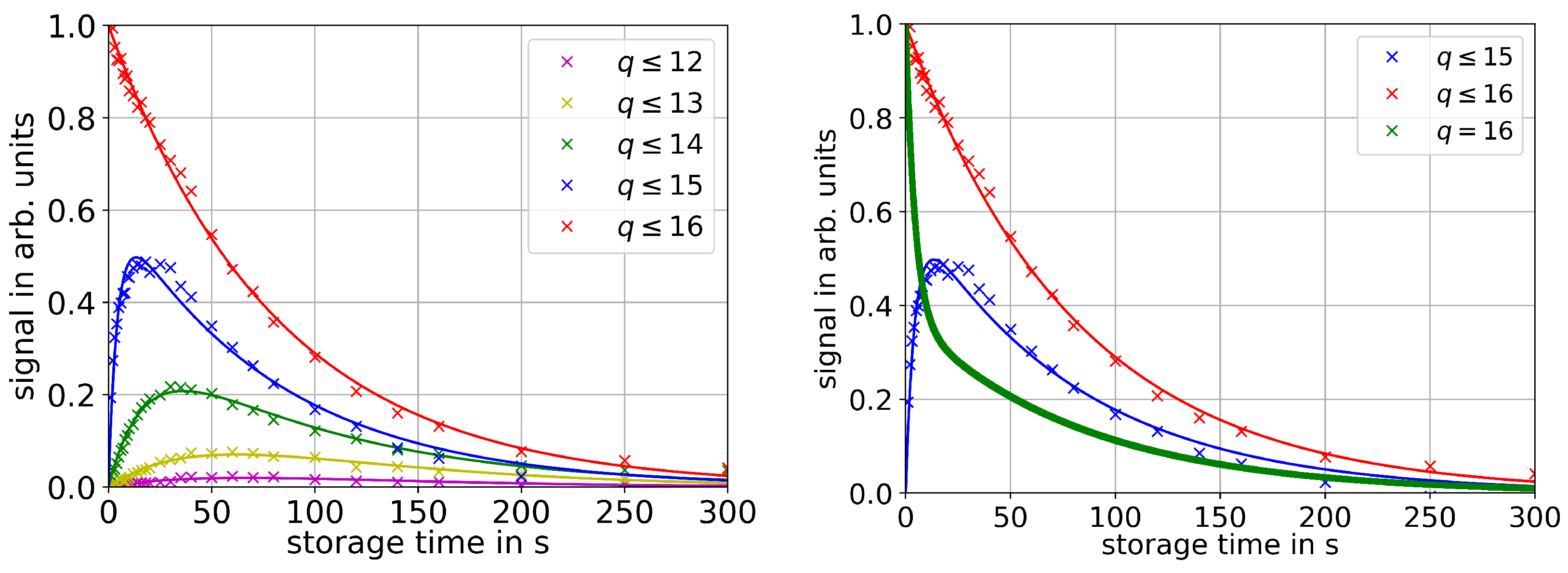
3.1. Charge Exchange

While measurements of the ion signal after various storage times yield the lifetime of the particle, they do not distinguish between various loss mechanisms such as elastic collisions or charge exchange. An ion that undergoes charge exchange with residual gas can still stay trapped. Even though it contributes to the ion signal on the MCP detector, it becomes irrelevant for most subsequent experiments. Therefore, further investigations into the process of charge exchange are necessary. The method of this measurement is already described in Section 2, and the results are plotted in Figure 2. Right after the capture process, only Ar 16 + -ions are observed, but the population of lower charge states rapidly increases. As expected, the plot of the charge states q 15 shows the steepest growth, and the position of the peak signal propagates to higher storage times for lower charge states. Simultaneously, the intensity of the maxima also decreases. Although theoretically their kinetic energy per charge would still be low enough to stay trapped, the charge states 12+ and 11+ are almost non-detectable. The relationship between the ion energy and trap potential seems to have a strong influence on the ion lifetime. As the energy per charge of the ions approaches the trap potential, other loss mechanisms than charge exchange become dominant for lower charge states.
Additionally, it is also possible to extract the population of Ar 16 + by subtracting the plot with q 15 from the one with q 16 . This yields the result shown in the right plot of Figure 2. There is a rapid decrease in Ar 16 + -ions within the first six seconds that corresponds to a lifetime of roughly (8.2 ± 3.7) s. After that, the decrease in ion signal becomes slower and the lifetime increases to (81.7 ± 0.1) s. According to simulations, both measured lifetimes are sufficiently long for the intended application of electron cooling [8]. It seems like the charge exchange is the dominant loss mechanism in the first phase because the population of ions with the lower charge state also rapidly increases. After that, the rate of charge exchange becomes slower. So far, it is not completely understood why there is such a steep decrease within the first few seconds. The second slower part can be utilized to estimate the pressure p inside the Penning trap using
τ = k B T σ p v
with the Boltzmann constant k B , temperature T, cross section σ , and velocity v. The cross section σ of one-electron capture can be calculated by the semi-empirical Müller–Salzborn equation
σ = 1.43 · 10 12 q 1.17 E I 2.76 c m 2 ,
where E I represents the ionization energy, that is for hydrogen molecules 15.43 eV [14,15]. Using the setup temperature of 12 K and the lifetime of the first and faster decrease ( τ 1 = 8.2 s) results in a pressure of (1.6 ± 0.9) · 10 13 mbar, while the second section ( τ 2 = 81.7 s) yields a pressure of (1.6 ± 0.4) · 10 14 mbar. As it is unlikely that the pressure improves by an order of magnitude within the short time period between these two sections, the lower pressure of the second section provides a more accurate estimation of the background pressure. The main contribution to the high uncertainty comes from the temperature as it is not precisely known inside the Penning trap. These results show an improvement on previous measurements [10], which can be explained by the lower pressure around the trap setup that was improved by an order of magnitude by baking the surrounding beamline and a regular thermal cycle of the 4 K-section of the system.

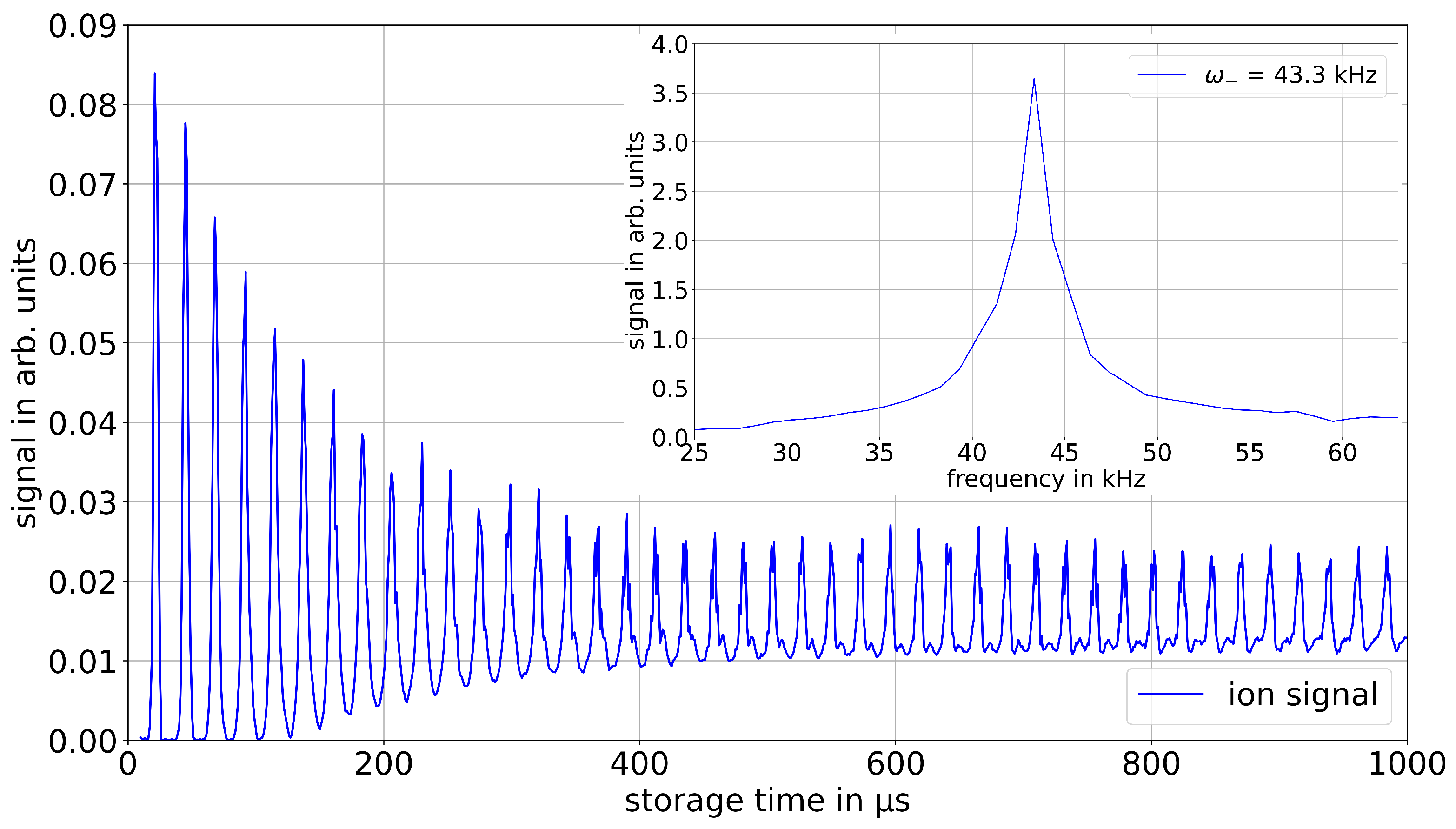
3.2. Magnetron Motion

Another property that can be accessed by observing the ion signal as a function of the storage time is the magnetron motion of the stored ions. As the trap potential is not ideally harmonic, standard equations for calculating frequencies of ion motions in a Penning trap cannot be directly applied for this setup. Varying the storage time within the first millisecond after capture yields a periodic structure in the ion signal as shown in Figure 3. The signal periodically rises and falls to zero within the first 100 μ s, while the peak signal continuously decreases. The peaks become wider as time progresses, and after about 100 μ s the signal does not drop down to zero anymore. This behavior can be explained by the magnetron motion of the stored ions. Depending on the phase of their magnetron motion, the radial position of the ions significantly changes. It seems like only ions within a small fraction of the magnetron phase are able to reach the MCP detector after ejection and contribute to the signal. The rest either collide with the setup, get lost after ejection, or just miss the detector because of an unfavorable trajectory. Additionally to the main peak, a less pronounced structure becomes visible after about 400 μ s, which corresponds to a slightly lower frequency. The ion bunch coming from the EBIT also shows a component of ions with slightly lower energy. Contrary to ideal penning traps, less kinetic energy results in this setup in a reduced magnetron frequency.
Right after the capture, the ions are still in a bunched form given by the EBIT and are all on approximately the same phase of their magnetron motion. This results in a high ion signal in the beginning. During the storage, the ion bunch thermalizes due to intrabeam scattering and the ions are distributed over the full length of the trap and revolution phases. After several milliseconds of storage, the thermalization process is finished and the ion signal stops fluctuating. Applying a fast Fourier transform of the periodic signal results in this case in a frequency of (43.3 ± 2.5) kHz, where the uncertainty is given by the FWHM of the frequency (see Figure 3). This measurement was done for various capture potentials and magnetic fields. The results are displayed in Table 1 below and are in very good agreement with simulations. In an ideal parabolic Penning trap with a harmonic potential the magnetron frequency ω can be calculated by equation
ω = 1 2 ( ω c ω c 2 2 ω z 2 ) ,
where ω c describes the cyclotron frequency and ω Z the axial frequency. The axial frequency is given by
ω z = q V 0 m d 2
with the capture potential V 0 and ion mass m [16]. Especially the trap parameter d is only applicable for a hyperbolic or compensated Penning trap. Using the measured magnetron frequencies, it is possible to calculate an ’effective’ trap parameter that allows for a rather accurate prediction of magnetron frequencies for other cases. With the data of the measurements and the mass of 40 Ar 16 + , this yields a trap parameter of (5.0 ± 0.6) cm as compared to a calculated d of (13.7 ± 0.1) cm for an ideal trap. As the magnetron frequency results from the E × B -field that is only present near the capture potential, it is reasonable that the “effective” trap parameter is significantly smaller than the calculated value. This knowledge may help to also employ a non-destructive method to measure not just the magnetron frequency but also the cyclotron frequency and the axial frequency, which also depend on the trap parameter.

4. Discussion

The lifetime of a charge state in the HITRAP cooling trap is an important parameter for future experiments with online ions. As they are in a higher charge state of up to 92+, it is expected that their lifetime is significantly lower than for Ar 16 + -ions. Simulations on U 92 + predict a cooling time for HCI using electron cooling in the order of a few seconds [8], so it is necessary that the lifetime is long enough to apply this cooling technique. To determine the lifetime of a charge state, measurements that distinguish between particle loss and charge exchange are necessary. The first steps towards this are the charge-sensitive measurements described in Section 3.1. These show that within the first few seconds, the rate of charge exchange is significantly larger. A possible explanation might be that the energy distribution of the ion cloud becomes broader in that time frame. As the employed method is energy-dependent, a broad energy distribution would prevent a clean separation of the charge states and significantly change the results of the measurement. Therefore, the implementation of a non-destructive detection method is planned that measures the cyclotron frequency of the stored ions. As this frequency is directly proportional to the ion charge and independent of their energy, this would allow for a more precise observation of the charge exchange. Such a non-destructive detector may also improve the measurement results of the magnetron frequency. This frequency was measured for various trapping conditions, and the results yielded an ’effective’ trap parameter of (5.0 ± 0.6) cm for the Penning trap that allowed for the prediction of the magnetron frequency for other conditions .

Author Contributions

Software, W.G. and D.N.; validation, M.H.; formal analysis, S.R.; investigation, S.R. and M.H.; resources, Z.A., F.H. and W.N.; writing—original draft preparation, S.R.; writing—review and editing, M.H., Z.A., S.F., W.G., F.H., D.N., N.S., S.T., G.V. and W.N.; visualization, S.R.; supervision, Z.A., F.H. and W.N.; project administration, Z.A., F.H. and W.N.; and funding acquisition, W.N. All authors have read and agreed to the published version of the manuscript.

Funding

We acknowledge support by the BMBF under contract numbers 05P19RDFAA and 05P21RDFA1, the Deutsche Forschungsgemeinschaft (DFG, German Research Foundation), and the Open-Access Publishing Fund of Technical University of Darmstadt.

Data Availability Statement

Data available on reasonable request from the authors.

Conflicts of Interest

The authors declare no conflict of interest.

Abbreviations

The following abbreviations are used in this manuscript:
GSIGSI Helmholtzzentrum für Schwerionenforschung GmbH
HCIhighly-charged ions
ESRexperimental storage ring
QEDquantum electrodynamics
RFQradiofrequency quadrupole
EBITelectron beam ion trap
MCPmicrochannel plate
FWHMfull width at half maximum

References

  1. Repp, J.; Böhm, C.; Crespo López-Urrutia, J.R.; Dörr, A.; Eliseev, S.; George, S.; Goncharov, M.; Novikov, Y.N.; Roux, C.; Sturm, S.; et al. PENTATRAP: A novel cryogenic multi-Penning-trap experiment for high-precision mass measurements on highly charged ions. Appl. Phys. B 2012, 107, 983–996. [Google Scholar] [CrossRef] [Green Version]
  2. Murböck, T.; Albrecht, S.; Andelkovic, Z.; Cazan, R.; Hannen, V.; Jöhren, R.; Vollbrecht, J.; Schmidt, S.; Segal, D.; Thompson, R.; et al. SpecTrap: Precision spectroscopy of highly charged ions-status and prospects. Phys. Scr. 2013, 2013, 014096. [Google Scholar] [CrossRef]
  3. Micke, P.; Leopold, T.; King, S.A.; Benkler, E.; Spieß, L.J.; Schmoeger, L.; Schwarz, M.; Crespo López-Urrutia, J.R.; Schmidt, P.O. Coherent laser spectroscopy of highly charged ions using quantum logic. Nature 2020, 578, 60–65. [Google Scholar] [CrossRef] [PubMed]
  4. Sturm, S.; Werth, G.; Blaum, K. Electron g-factor determinations in Penning traps. Ann. der Phys. 2013, 525, 620–635. [Google Scholar] [CrossRef]
  5. Arapoglou, I.; Egl, A.; Höcker, M.; Sailer, T.; Tu, B.; Weigel, A.; Wolf, R.; Cakir, H.; Yerokhin, V.A.; Oreshkina, N.S.; et al. g Factor of Boronlike Argon 40Ar13+. Phys. Rev. Lett. 2019, 122, 253001. [Google Scholar] [CrossRef] [PubMed] [Green Version]
  6. Versolato, O.O.; Schwarz, M.; Windberger, A.; Ullrich, J.; Schmidt, P.O.; Drewsen, M.; Crespo López-Urrutia, J.R. Cold highly charged ions in a cryogenic Paul trap. Hyperfine Interact. 2013, 214, 189–194. [Google Scholar] [CrossRef]
  7. Herfurth, F.; Andelkovic, Z.; Barth, W.; Chen, W.; Dahl, L.A.; Fedotova, S.; Gerhard, P.; Kaiser, M.; Kester, O.K.; Kluge, H.J.; et al. The HITRAP facility for slow highly charged ions. Phys. Scr. 9 2015, T166, 014065. [Google Scholar] [CrossRef]
  8. Maero, G. Cooling of Highly Charged Ions in a Penning Trap for HITRAP. Ph.D. Thesis, Rupertus-Carola University of Heidelberg, Heidelberg, Germany, 2008. [Google Scholar] [CrossRef]
  9. Fedotova, S. Experimental Characterization of the Hitrap Cooler Trap with Highly Charged Ions. Ph.D. Thesis, Rupertus-Carola University of Heidelberg, Heidelberg, Germany, 2013. [Google Scholar] [CrossRef]
  10. Andelkovic, Z.; Fischer, J.; Herfurth, F.; König, K.; Neidherr, D.; Nörtershäuser, W.; Shroff, M.; Trotsenko, S.; Vorobjev, G. Development of the HITRAP cooling trap and the EBIT offline ion source. Hyperfine Interact. 2019, 240, 29. [Google Scholar] [CrossRef]
  11. Geyer, S.; Sokolov, A.; Thorn, A.; Vorobyev, G.; Stöhlker, T.; Kester, O. Characterization of the SPARC-EBIT at GSI. J. Instrum. 2010, 5, C10003. [Google Scholar] [CrossRef]
  12. Andelkovic, Z.; Herfurth, F.; Kotovskiy, N.; König, K.; Maaß, B.; Murböck, T.; Neidherr, D.; Schmidt, S.; Steinmann, J.; Vogel, M.; et al. Beamline for low-energy transport of highly charged ions at HITRAP. Nucl. Instruments Methods Phys. Res. Sect. A Accel. Spectrometers 2015, 795, 109–114. [Google Scholar] [CrossRef]
  13. Chill, F. Vermessung der Pumpeigenschafen einer Kryogenen Oberfäche. Ph.D. Thesis, Goethe University Frankfurt am Main, Frankfurt am Main, Germany, 2015. [Google Scholar]
  14. Müller, A.; Salzborn, E. Scaling of cross sections for multiple electron transfer to highly charged ions colliding with atoms and molecules. Phys. Lett. A 1977, 62, 391–394. [Google Scholar] [CrossRef]
  15. Liu, J.; Salumbides, E.J.; Hollenstein, U.; Koelemeij, J.C.; Eikema, K.S.; Ubachs, W.; Merkt, F. Determination of the ionization and dissociation energies of the hydrogen molecule. J. Chem. Phys. 2009, 130, 174306. [Google Scholar] [CrossRef] [PubMed]
  16. Vogel, M. Particle Confinement in Penning Traps; Springer: Heidelberg, Germany, 2018; Volume 100, pp. 48–51. [Google Scholar]
Figure 1. The 40 cm long, cylindrical electrode stack that creates the electric field of the HITRAP cooling Penning trap with a central electrode segmented into four parts.
Atoms 10 00142 g001
Figure 2. Left: Ion signal for various storage times and charge states. The red plot contains all charge states in the trap, the blue one only the charge states 15+ and lower and so on, as indicated in the legend. Each signal was normalized to the initial signal of the red plot. Right: Additionally to the plots for charge states q 16 (red) and q 15 (blue), the deduced population of Ar 16 + -ions is plotted in green.
Atoms 10 00142 g002
Figure 3. Ion signal plotted over the storage time. The subplot in the top right corner shows the result of a fast Fourier transform of the ion signal.
Atoms 10 00142 g003
Table 1. Measured and simulated magnetron frequencies ω for various trap settings.
B-FieldCapture PotentialSimulated ω 2 π Measured ω 2 π
in Tin kVin kHzin kHz
3662 58.0 ± 1.8
3777 75.6 ± 1.2
37.583 81.6 ± 2.0
3883 86.7 ± 2.5
4645 43.3 ± 2.5
4864 63.5 ± 1.3
Publisher’s Note: MDPI stays neutral with regard to jurisdictional claims in published maps and institutional affiliations.

