Article

First Experiments with CRYRING@ESR †

by
Michael Lestinsky
1,*,
Esther Babette Menz
1,2,3,
Håkan Danared
4,
Claude Krantz
1,
Eva Lindroth
5,
Zoran Andelkovic
1,
Carsten Brandau
1,6,
Angela Bräuning-Demian
1,
Svetlana Fedotova
1,
Wolfgang Geithner
1,
Frank Herfurth
1,
Anton Kalinin
1,
Ingrid Kraus
1,
Uwe Spillmann
1,
Gleb Vorobyev
1 and
Thomas Stöhlker
1,2,3 on behalf of SPARC and the CRYRING@ESR collaboration
1
GSI Helmholtzzentrum für Schwerionenforschung, 64291 Darmstadt, Germany
2
Helmholtz-Institut Jena, 07743 Jena, Germany
3
Institut für Optik und Quantenelektronik, Friedrich-Schiller-Universität Jena, 07743 Jena, Germany
4
European Spallation Source, 221 00 Lund, Sweden
5
Fysikum, Department of Physics, Stockholm University, 106 91 Stockholm, Sweden
6
I. Physikalisches Institut, Justus-Liebig-Universität Giessen, 35392 Giessen, Germany
*
Author to whom correspondence should be addressed.
This paper is an extended version of our paper published in HCI 2022, Matsue, Japan.
Atoms 2022, 10(4), 141; https://doi.org/10.3390/atoms10040141
Submission received: 24 October 2022 / Revised: 10 November 2022 / Accepted: 11 November 2022 / Published: 16 November 2022
(This article belongs to the Special Issue 20th International Conference on the Physics of Highly Charged Ions)

Abstract

:
The low-energy heavy ion storage ring CRYRING was transported from Stockholm to Darmstadt, modernized and reconfigured, and recommissioned as CRYRING@ESR. The machine is now in operation with all installations in service and is available as a user facility for experiments proposed through the SPARC collaboration. During the 2020–2022 period, we brought a number of experimental installations into service and used them to measure first data: the ultra-cold electron cooler for merged-beam electron–ion collisions, the gas jet target for atomic collisions, a next-generation microcalorimeter-based X-ray spectroscopy setup, and others. Ions can be injected either in low charge states from a local ion source through a 300 keV/u RFQ linac, or in high charge states from the GSI accelerator chain through ESR. This allows for very broad access to ions across the entire periodic table. CRYRING@ESR is able to de- or accelerate ions and cool and store beams of isotopically pure species in a desired charge state. While the analysis is still largely ongoing, the first experimental data already show that the machine reached its expected performance level, and our high expectations regarding achievable resolution in spectroscopy experiments have been fulfilled. With access to new classes of ions available through ESR injection and a new generation of experimental instrumentation, CRYRING@ESR is a unique facility for experiments with heavy, highly charged ions. Here, we will review our present setup and machine performance, discuss the data from our first commissioning experiments and briefly preview the upcoming new installations for the coming years.

1. Introduction

CRYRING@ESR is a low-energy storage ring for heavy ions [1,2,3,4] and a key experimental facility for the SPARC collaboration [5,6]. The formerly Swedish CRYRING was transported from Stockholm to Darmstadt and integrated into the accelerator complex of GSI/FAIR, where it is located downstream from ESR. Ion beams can be injected into CRYRING@ESR from two different injection channels: heavy, highly charged ions can be injected from ESR, where they are decelerated to typically 10 MeV/u, cooled and transferred to CRYRING@ESR. Alternatively, stand-alone operation can be provided for a limited range of light ions from a local injector, with an ECR ion source terminal and a 300 keV/u RFQ linac.
The ring has been slightly modified from its previous Stockholm configuration. A new injection system can operate up to the maximum magnetic rigidity of CRYRING at 1.44 Tm, an extraction beamline was added, the circumference was extended to 54.17 m and the sequence of ring sections was adjusted to the boundary conditions of the cave at GSI. The ring has a dodecagonal shape and its lattice is largely similar to its previous Stockholm setup and operated at the same tune of Q x , y = 2.42 . The straight sections implement a repeating pattern of quadrupole and sextupole magnets for beam focusing in every second section. Interleaved are the six sections for injection, electron cooling, RF bunching and acceleration, extraction, a free experiment section and beam diagnostics.
Four sections of the ring are of particular interest for experimental installations. These are indicated in Figure 1. At the electron cooler, merged-beam ion–electron collisions can be studied either through the X-ray spectroscopy of radiative recombination [7,8,9] or via the detection of product ions from dielectronic recombination [10,11]. Overlapping with the straight ring section for extraction is a setup for collinear laser spectroscopy and fluorescence detection. From the extraction section, a short beamline stub branches out, where the extracted beam can be delivered to single-pass experiments, e.g., on surface modifications. The experimental section can be equipped with different installations for studying collision processes in the atomic and nuclear domain. These installations were contributed by the user community of SPARC and can be exchanged as needed during longer breaks between beamtime blocks. Presently, a dense gas jet target for gas species ranging from H 2 to Xe is installed at the center of this section [12] and currently equipped with a large solid angle detection system for nuclear fragments, CARME, installed just downstream [13,14].
The facility is in operation, and since 2021, regular beamtime service has been provided for experiments proposed by the user community and approved by the GSI/FAIR General Program Advisory Committee. In the following, we report on the machine performance and discuss first experimental data from two commissioning experiments. Details on presently realized and planned future experimental installations and their physics cases are given in the CRYRING@ESR physics book [6].

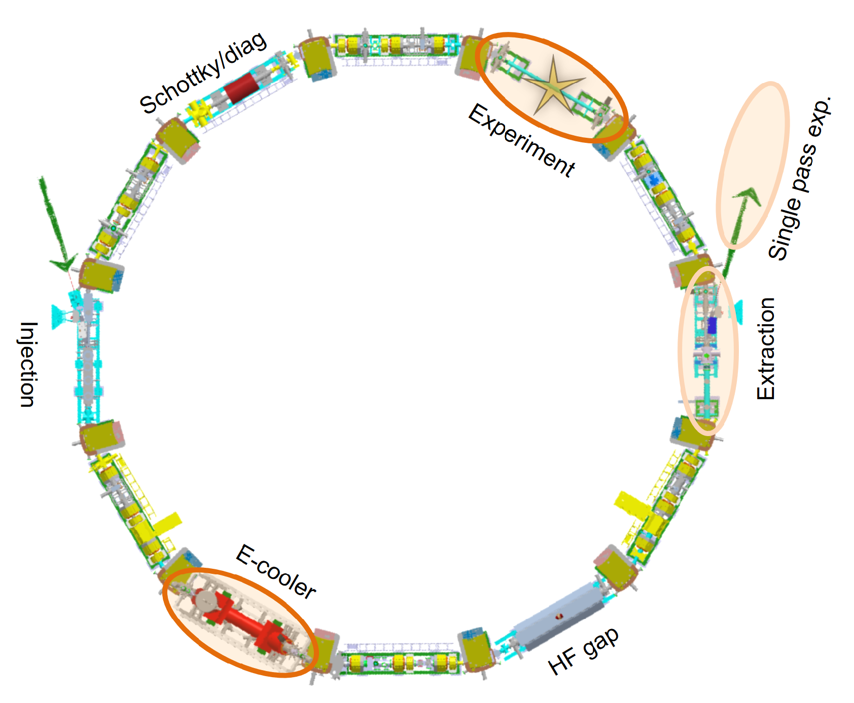
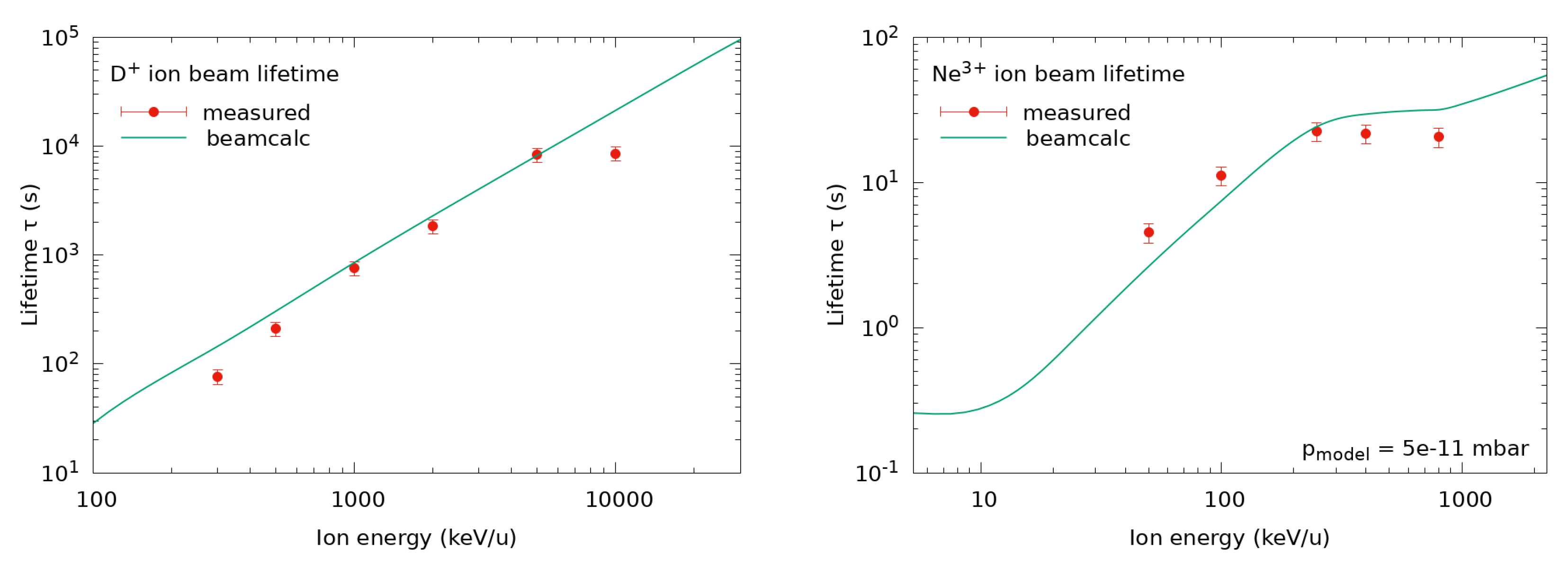
2. Machine Performance

A broad range of ions have been stored in CRYRING@ESR since its commissioning, and Table 1 gives an overview of ion species, storage energy, achieved ion beam intensity, beam lifetime at the final energy, and ion source used to produce them.
Here, beam lifetimes are given without electron cooling, as for high charge states of heavy ions in particular, the beam lifetime is significantly reduced by radiative recombination at the electron cooler. Beam lifetimes are derived for bunched beams from time-dependent measurements with a Schottky noise pickup. We estimate 15% systematic uncertainty for this method.
In order to predict the beam lifetimes for new ion species or beam conditions, our beamcalc model [15] includes atomic collisions of the circulating ions with residual gas through the processes of charge exchange, stripping reactions, Rutherford scattering, and radiative recombination at the electron cooler.
As the residual gas composition in CRYRING@ESR is presently not very well known, we approximate it with ratios of 90%, 9.5%, and 0.5% for H 2 , N 2 , and Ar, respectively. The mean ring pressure is derived from a set of six extractor-type vacuum gauges around the ring, and is estimated at 5 × 10 11 mbar on average during the 2020–2022 period.
To test the predictive power of beamcalc, we measured the energy-dependent beam lifetimes systematically for two ion species: once for a simple bare ion, D + , and once for an ion species with a fairly complex atomic shell, the N-like Ne 3 + . The data are presented in Figure 2 and show a reasonably good agreement between our observed lifetimes (red dot symbols) and the model predictions (solid green line). The staggered structure in the predicted lifetime of Ne 3 + is an effect of the particularly low beam energies for this ion, as in this range deeper-lying electronic shells of the projectile ions and the residual gas atoms are successively becoming accessible to collisionally induced atomic processes.
The investigations of beam lifetimes clearly show that we in fact have a regime of ‘stored beam’ in CRYRING@ESR, i.e., limited only by the vacuum conditions, and not merely ions circulating for a few rounds before the machine loses the beam. To further improve the beam lifetimes, we are presently implementing upgrades of the vacuum system.

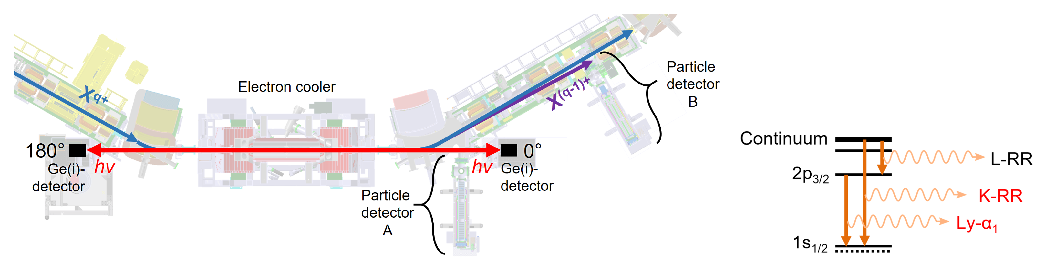
3. Electron–Ion Collision Spectroscopy at the Electron Cooler

The electron cooler of CRYRING@ESR [16] provides an ultra-cold electron beam co-moving with the stored beam for a distance of 1.1 m. With adiabatic magnetic expansion, the cooler is able to provide an electron beam with temperatures as low as k B T 1 meV and k B T 40 μ eV. The electrons serve as a heat bath for the circulating ions which, through Coulomb collisions, transfer their relative energy to a constant stream of cold electrons until equilibrium is reached and v i = v e . The cooler is in operation [17] and, besides its main function for beam cooling, is also an important instrument for electron–ion collision experiments on X-ray spectroscopy and dielectronic recombination, the principle setup and first results of which will be discussed in the remainder of this section.

3.1. Product Particle Detection

Ions recombining with an electron are diverted from the closed orbit of the stored beam at the next dipole magnet due to their reduced q / m ratio, and can be detected by either of two particle detector setups downstream of the dipole magnet behind the cooler. The detectors are mounted directly into the ring vacuum and movable by a combination of a precise stepper motor drive and a fast pneumatic drive. Both setups are designed to be able to operate close to the primary beam. During beam injection and cooling phases of the machine cycle, the detectors can be pneumatically retracted 50 mm away from the measurement position to clear the ring aperture.
For ions in low charge states ( q 20 ), a YAP:Ce scintillation detector [18,19] is installed directly behind the dipole magnet (position A in Figure 3). YAP:Ce is a convenient material for this type of application, as it has a good light yield, short decay time, high radiation hardness, and is non-hygroscopic. The crystal is mounted directly into the ring vacuum, and its scintillation light is coupled out through an optical window, where it can be observed by a photomultiplier.
For heavy, highly charged ions (charge states 30 q 92 ), a new particle detector based on a design by Rinn [20] was set up at a position further downstream in the CRYRING@ESR (position B in Figure 3). This position moreover allows for a simultaneous installation of X-ray detectors at the 0° window port. With realistic (if optimistic) assumptions regarding achievable electron density and ion beam intensity, we expect up to ∼few MHz count rates for down-charged product ions in all experiments at the electron cooler with highly charged ions. This increases the demand on short pulse duration, as for coincidence measurements single-particle counting needs to be maintained with very high efficiency throughout the course of a beamtime campaign. We use a channel electron multiplier (CEM) with extended dynamic range, which is able to operate in single particle counting mode up to 10 MHz incidence rate and with a pulse duration of 5 ns. An additional consideration with heavy, highly charged ions is radiation hardness, which is taken into account by using an indirect setup: the sensitive surface is a stainless steel plate on which the product ions impinge. Only the secondary electrons emitted from this plate are then guided onto a CEM, which is thereby never exposed directly to the hard impact of heavy ions. The assembly is encased in a grounded housing and has a typical working distance of 10 mm from the closed orbit for Pb 82 + or U 91 + .

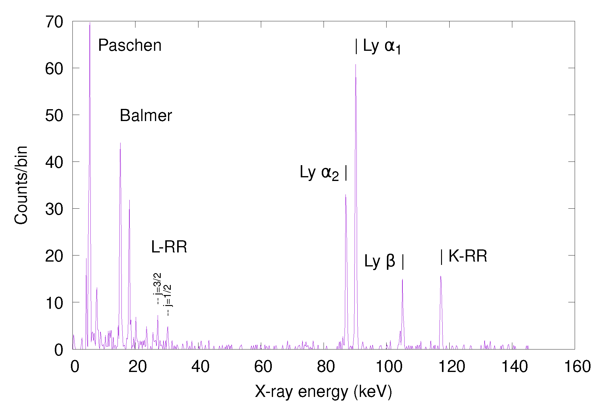
3.2. The X-ray Spectroscopy Setup

X-rays produced by the process of radiative recombination can be observed at 0° and 180° window pockets at the e-cooler, as detailed in the schematic overview of our setup given in Figure 3. The window pockets are equipped with thin Be windows with a lower limit for measuring X-rays of 1 keV. In practice, the lower limit is rather at the endpoint of Bremsstrahlung from the electrons in the cooler, which for 10 MeV/u ions is at 5.5 keV.
The radiative capture of a free electron by an ion either populates the ground state directly through K-RR, or mediates through some excited level followed by a cascade of characteristic radiation as the product ion de-excites to the ground state (c.f. Figure 3, right panel). First X-ray spectra were recently published for an H-like Pb 81 + product ion formed from radiative recombination into bare lead [8], the 0° X-ray spectrum is given as an example in Figure 4.
The geometry of the 0° and 180° windows is an ideal configuration because it eliminates the largest systematic uncertainty in determining exact energies of the characteristic lines, which arise from correcting the Doppler shift. At this geometry, the angle between the momentum vector of the emitting ion and the direction of the X-ray detector remain strictly constant as the moving ion cascades to its ground state. Additionally, with the lower beam energies at CRYRING@ESR, the quantity of Doppler correction is significantly reduced when compared to previous data from ESR [21]. Further, with this geometry an intrinsic Doppler correction of the observed lines can be achieved by correlating the spectra in forward and backward directions. New data on the characteristic radiation of U 90 + was recently measured using a new type of magnetic microcalorimeter, and is presently under analysis [9]. These microcalorimeters improve the X-ray line width by a factor of 20 over conventional Ge(i) detectors, and thus further reduce uncertainties in the determination of X-ray line centers from measured spectra. In recent years, the theory of strong-field QED has seen significant progress [22], with remaining uncertainties at the level of our present experimental precision. The setup at CRYRING@ESR has the potential to further improve on these uncertainties, e.g., aiming at 1 s Lamb-shift measurements in H-like U 91 + with a precision high enough for testing one-electron QED corrections of the second order in α [6].

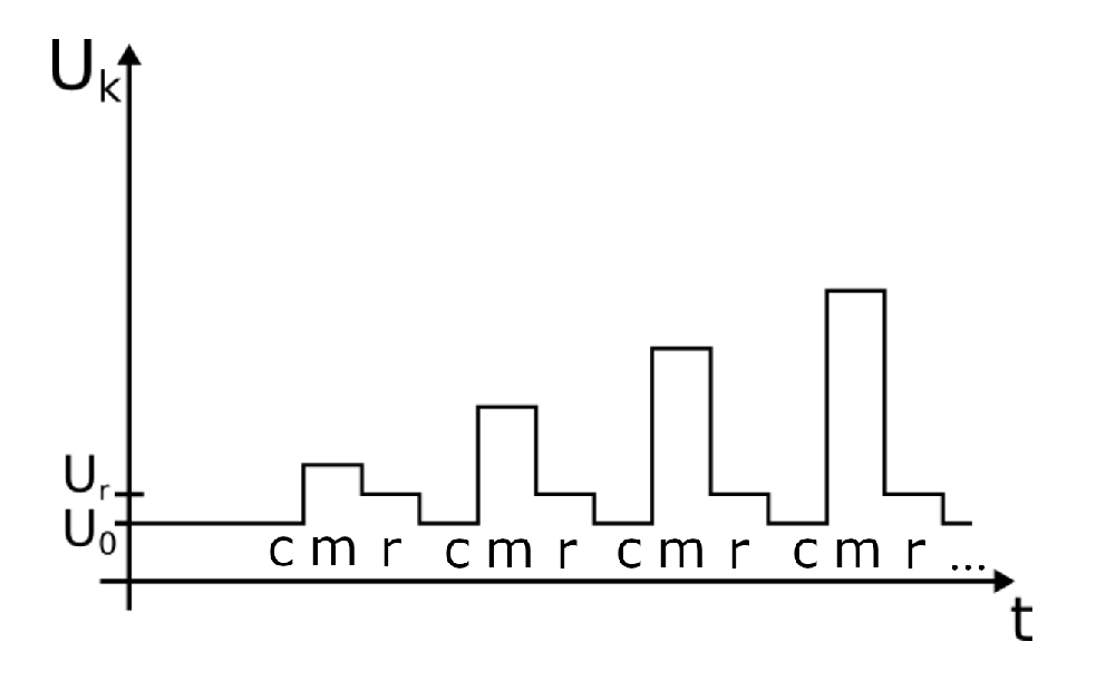
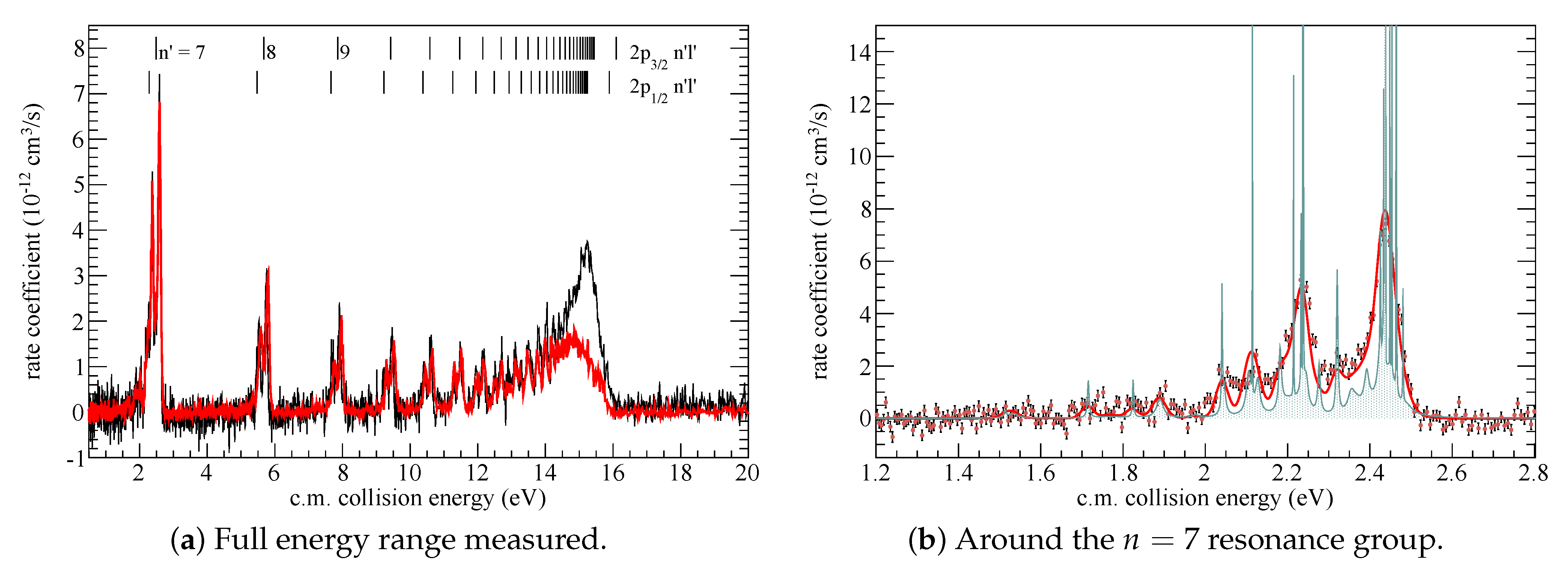
3.3. The Dielectronic Recombination Setup and First Results on Ne 7 +

The second relevant electron–ion recombination process is dielectronic recombination (DR). DR is a two-step process, and is time-inverse to the Auger process. At discrete energy levels, free electrons in the continuum of the ions fulfill a resonant condition with an electronic transition in the atomic shell of the ions. The capture of the free electron first excites an inner electron of the ion. This forms a short-lived doubly excited, auto-ionizing state, and if the ion de-excites radiatively in a second step, the DR process is complete.
With the ultra-cold electron beam at the cooler, this process can be measured with high resolution [10]. Since the cross sections for DR are typically orders of magnitude larger than for RR, DR is an important process in determining the charge state balance of astrophysical plasma, and experimental merged-beam recombination rate coefficients provide relevant data for modelling such environments in the analysis of astrophysical spectra. Moreover, the availability of highly charged heavy ions at the new CRYRING@ESR installation, in combination with the extremely cold electron beam, provides a unique opportunity to study atomic transitions in strong fields and nuclear effects, such as isotopic shifts or hyperfine contributions.
To measure a dielectronic recombination spectrum, we parameterize the electron energy with a potential ramp on the electron gun and tailor it specifically for each ion and range of collision energies. In the ramp, a sequence of three discrete steps is repeated, as follows.
The measurement steps m scan the energy range and alternate with steps at the cooling energy c and a particular reference energy r (see Figure 5 for a scheme). The duration of each step is typically 10 ms, and the number of repetitions is adjusted to the ion beam lifetime. The electron energy is controlled through a stack of two power supplies: a stable main HV supply which provides a constant bias voltage U 0 and a HV amplifier which produces a detuning voltage U k with respect to U 0 . The fast slew rate of the HV amplifier can support short step lengths on the order of milliseconds. The measurement ramps can be programmed and activated as part of our integrated control and data acquisition system.
With prior reference data from exactly the same device obtained during its time in Stockholm, we selected Ne 7 + [23,24] as a first system to verify the proper functioning of the electron cooler using DR measurements after re-installation at GSI. Ne 7 + is a lithium-like system with an inner active electron in the 2 s 1 / 2 ground state. Δ n = 0 DR is observed when dielectronic capture causes an inner electron to excite within the L-shell to 2 p 1 / 2 or 2 p 3 / 2 levels and the outer active electron is captured from the ion’s continuum into n l Rydberg levels of a Ne 6 + daughter ion. The lowest resonance group for n = 7 is identified at around 2 eV collision energy and a sequence of resonances for higher Rydberg levels follows, culminating in the characteristic cusp for n at 15.89 eV and 16.09 eV.
Figure 6a compares our measurement to the data from Stockholm. As we did not yet measure absolute rate coefficients, our data are scaled to match the Stockholm spectrum. Additionally, our energy range is multiplied by a factor of 1.015 and shifted towards higher energies by 0.15 eV. The measurement at Darmstadt yielded a more pronounced cusp at the series limits, indicating a higher cut-off number due to field ionization. This was due to the different ion beam energies during the experiment: in Stockholm the beam was accelerated to 11.4 MeV/u whereas in Darmstadt a beam with 4 MeV/u was used. Apart from this, the agreement between the measurements is excellent, particularly when observing the DR resonance line-widths.
A small cut-out from the measured spectrum for the region around the n = 7 group is given in Figure 6b. Shown are our experimental rate coefficients (point symbols) with results from previous relativistic many-body perturbation theory calculations [24] for the DR cross section σ ( E ) in its natural line width (teal filled area) and the derived rate coefficient α ( E ) = v · σ ( E ) when convolved with electron temperatures prevalent in our experiment. The theoretical cross section for the n = 7 group comprises a total of 74 states, and it can be seen that the experimental resolution is already near the natural line width for many of the lines shown. The electron temperatures were derived by two methods: once by fitting the theoretical cross section to our measured data, where we derived k B T = 52 μ eV and k B T = 2.59 meV, and once by calculating the electron plasma temperatures from the specific machine settings during this measurement [15] with k B T = 49.8 μ eV and k B T = 2.6 meV. However, a resonance group at an energy of 2 eV is certainly not ideal for determining k B T from a fit of DR data, and that another ion species with lower-energy DR resonances may be more suited as an ultimate test case (e.g., the two Li-like systems F 6 + [25] and Sc 18 + [26]). Nevertheless, both methods of deriving the electron temperatures (fit and beamcalc) are in excellent agreement, and thus we conclude that the electron cooler is functioning nominally after its move. This is a very encouraging confirmation of the resolving power, indicating that CRYRING@ESR currently has the most highly resolving electron cooler of any storage ring for highly charged ions, and is particularly important for the future program of precision experiments. Since the test measurement on Ne 7 + , further DR experiments were performed on Be-like Pb 78 + [27], He-like O 6 + [28], and O-like Ne 2 + [29]; their data reduction and analysis are still ongoing.

4. Summary and Outlook

CRYRING@ESR has successfully served its first period of user experiments. Preliminary results from the ongoing data analysis confirm that our high expectations regarding the possible resolution have been fulfilled. Further work on improving the vacuum conditions and the ion beam intensity available for injection into the ring is currently in progress.
In the meantime, new types of experimental instrumentation have been set up, and the next generation of experiments is in preparation. With the integration of CRYRING@ESR into the GSI accelerator complex, new classes of ion beams, up to and including bare U 92 + , have become available. With the low beam energies in this ring, new limits on experimental precision for slow atomic and nuclear collisions are in reach. These will explore ion–atom collisions in the atomic and nuclear domain as well as electron–ion collisions using ultra-cold, merged electron beams or a dense, transverse electron target. In the mid-term future, experiments on a completely new regime of ion–ion collisions are being prepared.
The heavy-ion storage ring, which first started routine operation at Stockholm in the early 1990s [30], is ready to explore new frontiers in the fields of strong-field atomic physics and low-energy nuclear reactions.

Author Contributions

Investigation, all authors; resources, E.L.; visualization, M.L. and E.B.M.; formal analysis: E.B.M. and M.L.; writing—original draft preparation, M.L. and E.B.M.; writing—review and editing, all authors. All authors have read and agreed to the published version of the manuscript.

Funding

C.B. is supported by the German Federal Ministry of Education and Research (BMBF) under contracts 05P15RGFAA and 05P19RGFA1. E.L. acknowledges support by the Swedish Research Council for grant No. 2020-03315. T.S. has received support by the German Federal Ministry of Education and Research (BMBF) under contracts 05P19SJFAA and 05P19VHFA1.

Data Availability Statement

Not applicable.

Acknowledgments

The authors would like to thank the Operations department of GSI for their support and B. Zhu for providing the original X-ray spectroscopy data of the Pb 82 + radiative recombination experiment. Results are based on R&D in the context of FAIR Phase-0 at GSI, Darmstadt (Germany).

Conflicts of Interest

The authors declare no conflict of interest.

References

  1. Danared, H.; Andler, G.; Björkhage, M.; Blom, M.; Brännholm, L.; Carlé, P.; Ehrnstén, K.; Engström, M.; Hedqvist, A.; Hellberg, F.; et al. LSR—Low-Energy Storage Ring; Technical Design Report; Manne-Siegbahn Laboratory, Stockholm University: Stockholm, Sweden, 2011. [Google Scholar]
  2. Lestinsky, M.; Angert, N.; Bär, R.; Becker, R.; Bevcic, M.; Blell, U.; Bock, W.; Bräuning-Demian, A.; Danared, H.; Dolinskyy, O.; et al. CRYRING@ESR: A Study Group Report; Project Study; GSI: Darmstadt, Germany, 2012. [Google Scholar]
  3. Lestinsky, M.; Bräuning-Demian, A.; Danared, H.; Engström, M.; Enders, W.; Fedotova, S.; Franzke, B.; Heinz, A.; Herfurth, F.; Källberg, A.; et al. CRYRING@ESR: Present Status and Future Research. Phys. Scr. 2015, T166, 014075. [Google Scholar] [CrossRef]
  4. Herfurth, F.; Andelkovic, Z.; Bai, M.; Bräuning-Demian, A.; Chetvertkova, V.; Geithner, O.; Geithner, W.; Gorda, O.; Litvinov, S. Commissioning of the Low Energy Storage Ring Facility CRYRING@ESR. In Proceedings of the COOL’17, Bonn, Germany, 18–22 September 2017; JACoW: Geneva, Switzerland, 2018; pp. 81–83. [Google Scholar]
  5. SPARC Collaboration. Available online: https://www.gsi.de/SPARC/ (accessed on 15 October 2022).
  6. Lestinsky, M.; Andrianov, V.; Aurand, B.; Bagnoud, V.; Bernhardt, D.; Beyer, H.; Bishop, S.; Blaum, K.; Bleile, A.; Borovik, A.; et al. Physics book: CRYRING@ESR. Eur. Phys. J. Spec. Top 2016, 225, 797–882. [Google Scholar] [CrossRef] [Green Version]
  7. Hengstler, D.; Schötz, C.; Krantz, M.; Geist, J.; Fleischmann, A.; Gastaldo, L.; Enss, C.; Gassner, T.; Märtin, R.; Weber, G.; et al. maXs—Cryogenic Micro-Calorimeter Arrays for High Resolution X-ray Spectroscopy Experiments at FAIR; Technical Design Report; Kirchhoff-Institut für Physik, Univ.: Heidelberg, Germany, 2014. [Google Scholar]
  8. Zhu, B.; Gumberidze, A.; Over, T.; Weber, G.; Andelkovic, Z.; Bräuning-Demian, A.; Chen, R.J.; Dmytriiev, D.; Forstner, O.; Hahn, C.; et al. X-ray emission associated with radiative recombination for Pb82+ ions at threshold energies. Phys. Rev. A 2022, 105, 052804. [Google Scholar] [CrossRef]
  9. Pfäfflein, P.; Allgeier, S.; Bernitt, S.; Fleischmann, A.; Friedrich, M.; Hahn, C.; Hengstler, D.; Herdrich, M.O.; Kalinin, A.; Kröger, F.M.; et al. Integration of maXs-type microcalorimeter detectors for high-resolution X-ray spectroscopy into the experimental environment at the CRYRING@ESR electron cooler. Phys. Scr. 2022, 97, 114005. [Google Scholar] [CrossRef]
  10. Schippers, S. Electron-ion merged-beam experiments at heavy-ion storage rings. Nucl. Instrum. Methods B 2015, 350, 61. [Google Scholar] [CrossRef] [Green Version]
  11. Andelkovic, Z.; Brandau, C.; Dumchev, M.; Ehresmann, A.; Geithner, W.; Georgiadis, A.; Hannen, V.; Lestinsky, M.; Litvinov, Y.; Nörtershäuser, W.; et al. Experimental Instrumentation of CRYRING@ESR; Technical Design Report; FAIR: Darmstadt, Germany, 2015. [Google Scholar]
  12. Petridis, N.; Lestinsky, M.; Kallberg, A.; Schmidt, H.T.; Litvinov, Y.A.; Grisenti, R.E. Technical Design Report: The CRYRING Internal Jet Target; Technical Report; FAIR: Darmstadt, Germany, 2018. [Google Scholar]
  13. Bruno, C.G.; Davinson, T.; Lederer-Woods, C.; Woods, P.J.; Coleman-Smith, P.J.; Cordwell, M.; Grant, A.; Lazarus, I.; Morrall, P.; Pucknell, V.F.E.; et al. Design, Construction and Commissioning of an In-Ring Spectrometer for Nuclear Reaction Studies at CRYRING; Technical Report; FAIR: Darmstadt, Germany, 2018. [Google Scholar]
  14. Bruno, C.; Marsh, J.; Davinson, T.; Woods, P.; Black, P.; Braeuning-Demian, A.; Glorius, J.; Hall, O.; Headspith, A.; Hindley, P.; et al. CARME—The CRYRING Array for Reaction MEasurements. in preparation.
  15. Lestinsky, M. Beamcalc. Available online: http://web-docs.gsi.de/~lestinsk/beamcalc/ (accessed on 1 October 2022).
  16. Danared, H.; Källberg, A.; Andler, G.; Bagge, L.; Österdahl, F.; Paál, A.; Rensfelt, K.G.; Simonsson, A.; Skeppstedt, Ö.; af Ugglas, M. Studies of electron cooling with a highly expanded electron beam. Nucl. Instrum. Methods A 2000, 441, 123–133. [Google Scholar] [CrossRef]
  17. Krantz, C.; Andelkovic, Z.; Brandau, C.; Dimopoulou, C.; Geithner, W.; Hackler, T.; Hannen, V.; Herfurth, F.; Hess, R.; Lestinsky, M.; et al. Recommissioning of the CRYRING@ESR Electron Cooler. In Proceedings of the 12th International Particle Accelerator Conference, Campinas, SP, Brazil, 24–28 May 2021; JACoW: Geneva, Switzerland, 2021. [Google Scholar]
  18. Menz, E.B. A Scintillation Particle Detector for Recombination Experiments at CRYRING@ESR. Master’s Thesis, Friedrich-Schiller-Universität Jena, Jena, Germany, 2018. [Google Scholar]
  19. Hahn, C.; Menz, E.; Pfäfflein, P.; Weber, G.; Stöhlker, T. A scintillator-based particle detector for CRYRING@ESR. X-ray Spectrom. 2020, 49, 338. [Google Scholar] [CrossRef] [Green Version]
  20. Rinn, K.; Müller, A.; Eichenauer, H.; Salzborn, E. Development of single-particle detectors for {keV} ions. Rev. Sci. Instrum. 1982, 53, 829–837. [Google Scholar] [CrossRef]
  21. Gumberidze, A.; Stöhlker, T.; Banaś, D.; Beckert, K.; Beller, P.; Beyer, H.F.; Bosch, F.; Hagmann, S.; Kozhuharov, C.; Liesen, D.; et al. Quantum Electrodynamics in Strong Electric Fields: The Ground-State Lamb Shift in Hydrogenlike Uranium. Phys. Rev. Lett. 2005, 94, 223001. [Google Scholar] [CrossRef] [PubMed] [Green Version]
  22. Yerokhin, V.A.; Shabaev, V.M. Lamb Shift of n = 1 and n = 2 States of Hydrogen-like Atoms, 1 ≤ Z ≤ 110. J. Phys. Chem. Ref. Data 2015, 44, 033103. [Google Scholar] [CrossRef]
  23. Böhm, S.; Müller, A.; Schippers, S.; Shi, W.; Fogle, M.; Glans, P.; Schuch, R.; Danared, H. Experimental NV and Ne VIII low-temperature dielectronic recombination rate coefficients. Astron. Astrophys. 2005, 437, 1151–1157. [Google Scholar] [CrossRef]
  24. Lindroth, E. Many-body perturbation theory applied to dielectronic recombination resonances. Hyperfine Interact. 1998, 114, 219–227. [Google Scholar] [CrossRef]
  25. Tokman, M.; Eklöw, N.; Glans, P.; Lindroth, E.; Schuch, R.; Gwinner, G.; Schwalm, D.; Wolf, A.; Hoffknecht, A.; Müller, A.; et al. Dielectronic recombination resonances in F6+. Phys. Rev. A 2002, 66, 012703. [Google Scholar] [CrossRef]
  26. Lestinsky, M.; Lindroth, E.; Orlov, D.A.; Schmidt, E.W.; Schippers, S.; Böhm, S.; Terekhov, A.S.; Müller, A.; Wolf, A. Screened Radiative Corrections from Hyperfine-Split Dielectronic Resonances in Lithiumlike Scandium. Phys. Rev. Lett. 2008, 100, 033001. [Google Scholar] [CrossRef] [PubMed]
  27. Fuchs, S.; et al. in preparation.
  28. Biela-Nowaczyk, W.; et al. in preparation.
  29. Menz, E.B. Preparation and Realization of first Dielectronic Recombination Experiments at CRYRING@ESR. Ph.D. Thesis, Friedrich-Schiller-Universtität Jena, Jena, Germany. in preparation.
  30. Abrahamsson, K.; Andler, G.; Bagge, L.; Beebe, E.; Carlé, P.; Danared, H.; Egnell, S.; Ehrnstén, K.; Engström, M.; Herrlander, C.J.; et al. CRYRING—A synchrotron, cooler and storage ring. Nucl. Instrum. Methods B 1993, 79, 269. [Google Scholar] [CrossRef]
Figure 1. Schematic overview of CRYRING@ESR. The four areas relevant to experimental installations are highlighted.
Atoms 10 00141 g001
Figure 2. Energy-dependent ion beam lifetimes for D + (left) and Ne 3 + (right). Measured data (red dot symbols) are compared with our simple beamcalc model [15] (solid green line).
Atoms 10 00141 g002
Figure 3. Top view of the electron cooler section with a schematic of the setup for X-ray spectroscopy (left image). The right image schematically illustrates an example cascade pathway for X-ray emission following the capture of a free electron into a bare ion forming an H-like X-ray-emitting product ion.
Atoms 10 00141 g003
Figure 4. X-ray spectrum for Pb 82 + + e Pb 81 + + h ν measured with a Ge(i) detector at the 0° window and in coincidence with particle detection at detector position ‘B’ as indicated in Figure 3. A detailed analysis of the X-ray spectra in forward and backward directions is given in [8].
Atoms 10 00141 g004
Figure 5. Schematic potential ramp on the electron cooler gun in DR experiments.
Atoms 10 00141 g005
Figure 6. Merged-beams recombination rate coefficient for DR of Ne 7 + + e Ne 6 + . The vertical lines at the top of the graph indicate the positions of Rydberg levels populated by the dielectronic capture. Panel (a) shows our new data (black line) with the previous results from Stockholm (red line) [23] for the same species. Panel (b) shows our data in comparison with theoretical data [24]: A theoretical merged-beam rate coefficient, convolved with the electron temperatures for our cooler setting is shown as a red line, its underlying cross section in natural line widths is indicated by the teal filled area. Please see the main text for details. The final analysis will be given in [29].
Atoms 10 00141 g006
Table 1. Overview of the ion species hitherto provided in CRYRING@ESR with beam energy at injection and storage, achieved intensity, beam lifetimes at the final energy, and the ion source used for beam production.
IonEnergyIntensityLifetimeIon Source
(MeV/u)(Particles)(s)
H 2 + 0.324 1 · 10 8 5.4MINIS + RFQ
D + 0.316 1 · 10 7 6000MINIS + RFQ
Li + 0.0052 1 · 10 7 9MINIS 1
C + 0.0030.69 5 · 10 6 5MINIS 1
O 6 + 0.310 5 · 10 5 250ECR + RFQ
Ne 2 + 0.0041 1 · 10 7 18ECR 1
Ne 7 + 0.34 1 · 10 6 80ECR + RFQ
Mg + 0.0010.17 3 · 10 6 7MINIS 1
Ar 18 + 13 1 · 10 6 600ESR
Au 78 + 10 3 · 10 6 24ESR
Pb 78 + 10 5 · 10 6 28ESR
U 91 + 10 2 · 10 6 20ESR
1 RFQ operated only as beamguide.
Publisher’s Note: MDPI stays neutral with regard to jurisdictional claims in published maps and institutional affiliations.

