
The Analysis and Verification of IMT-2000 Base Station Interference Characteristics in the FAST Radio Quiet Zone

 , , , , ,
Abstract
:1. Introduction
2. Analysis Object
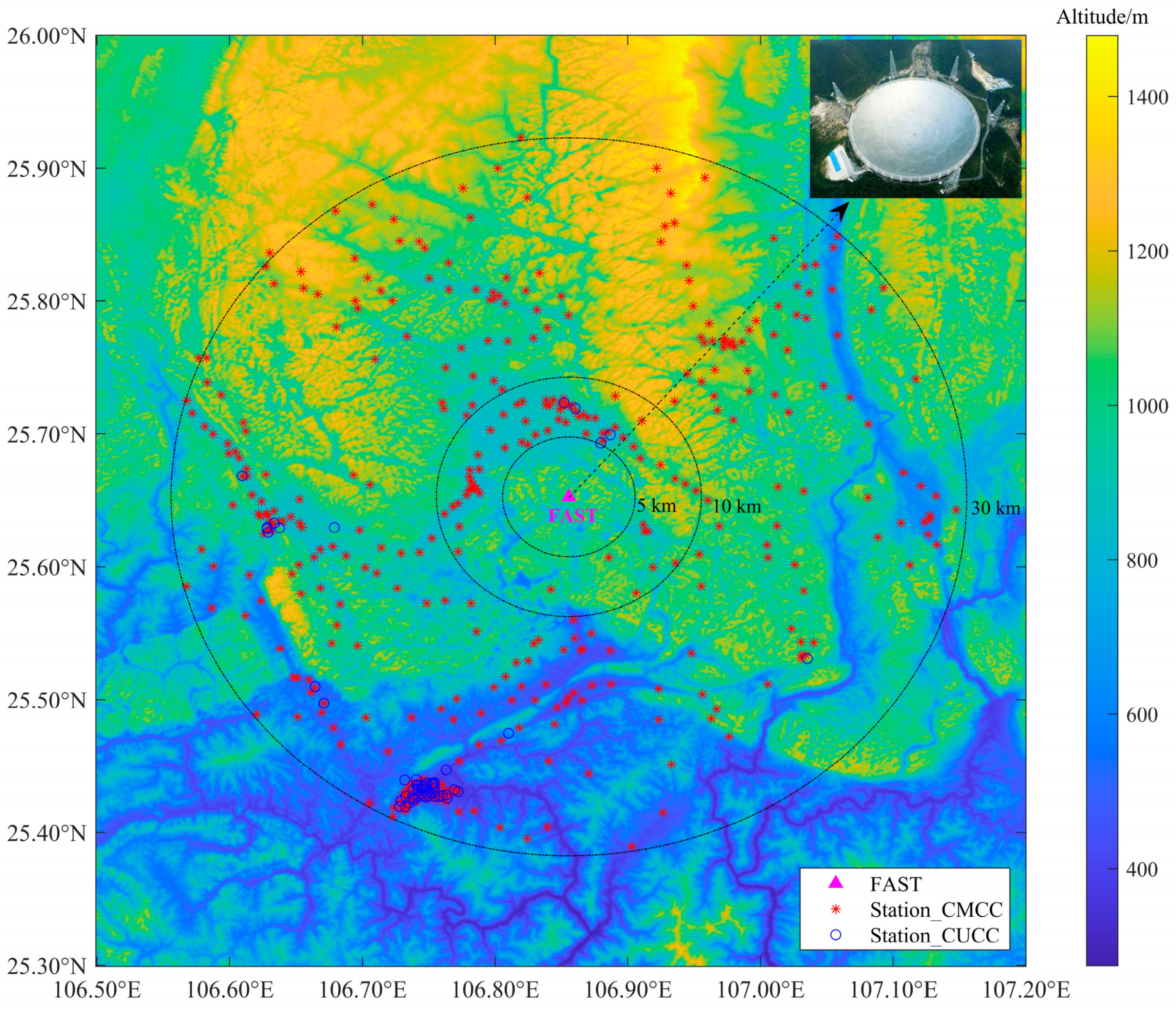
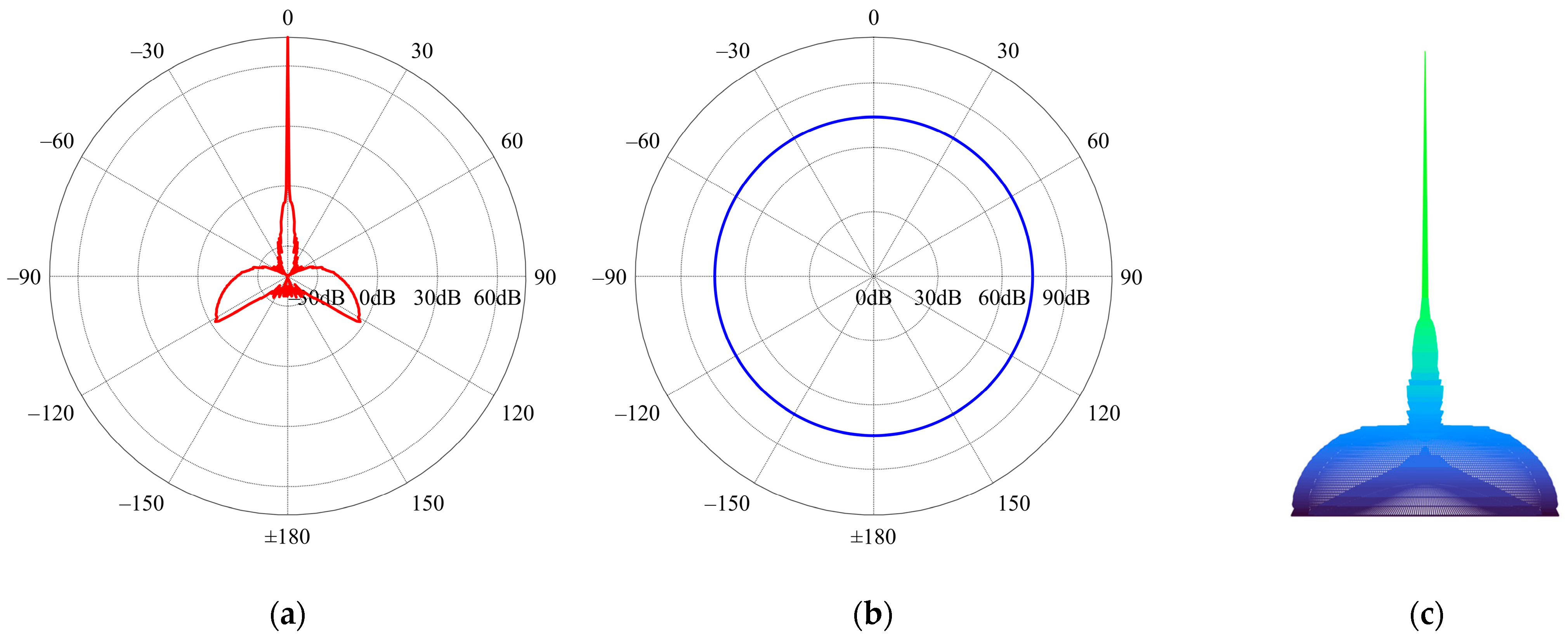
2.1. FAST
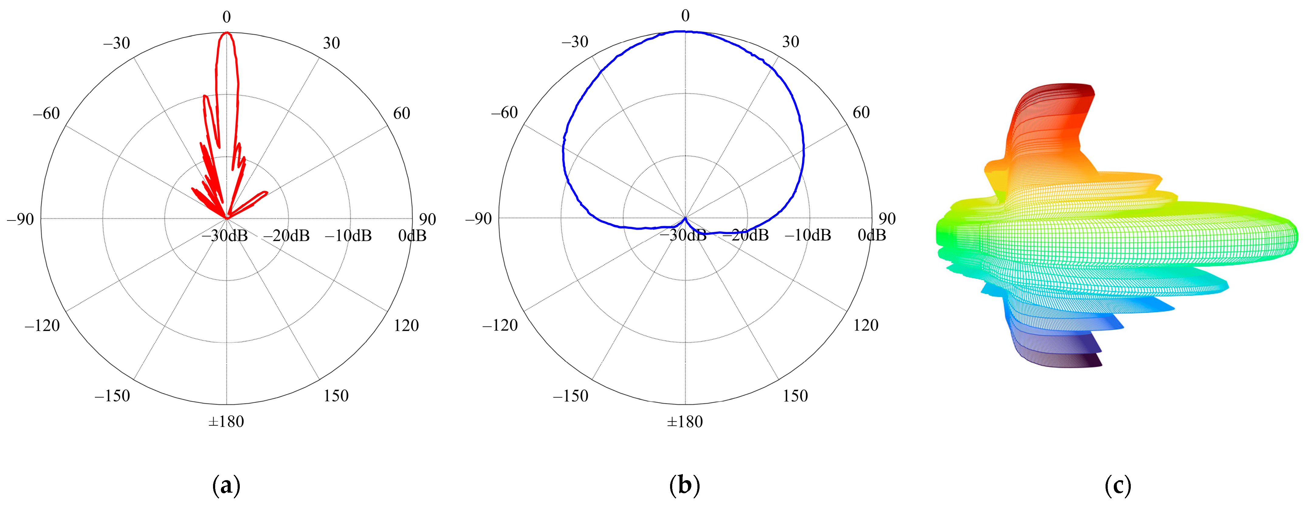
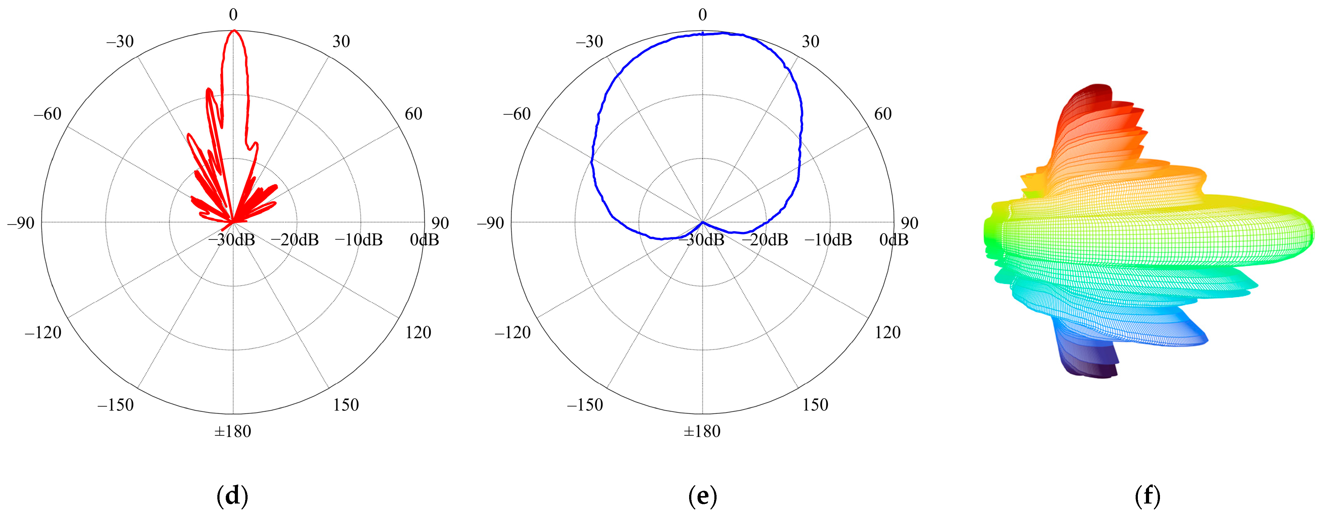
2.2. IMT-2000 Base Station
3. EMI Analysis
3.1. Analysis Method
- (1)
- Sub-model 1—Propagation close to the Earth’s surface: when the height of the transmitting and receiving antenna is low to the ground, with the maximum radiation direction along the surface, radio waves mainly propagate along the surface of the Earth. At this time, the transmission loss mainly includes free-space basic transmission loss, diffraction loss, clear-air effect, atmospheric attenuation, and other factors.
- (2)
- Sub-model 2—Anomalous propagation: atmospheric propagation mainly refers to the anomalous propagation of the atmospheric layers, namely, the atmospheric waveguide phenomenon.
- (3)
- Sub-model 3—Troposcatter propagation: affected by different solar irradiation intensities, thus forming an uneven propagation medium in the troposphere and causing scattering. The troposcatter transmission loss mainly considers the basic troposcatter transmission loss, rain–snow precipitation attenuation, and atmospheric absorption loss.
- (4)
- Sub-model 4—Ionospheric propagation: for long-haul and low-frequency predictive links, it is essential to consider the ionospheric scattering transmission loss caused by sporadic-E, mainly including the one-hop propagation mode and two-hop propagation mode.
- (5)
- Set relevant parameters based on the device and environment: FAST and IMT-2000 base station locations, frequencies, heights of transceiver antennas, environment type, time probability, location probability, and other basic path information parameters. Then, determine the propagation parameters such as the propagation distance, path midpoint position, sea propagation length, path elevation angle, refractive index, precipitation probability, equivalent Earth radius, effective height, and path roughness parameters.
- (6)
- Free-space basic transmission loss: when the transmitting and receiving antennas are located within the “visible” distance from each other, the radio wave propagates point-to-point along a straight line without reflection or scattering.
- (7)
- When the transmitting and receiving antennas are beyond the line-of-sight range, radio waves propagate mainly through diffraction, including diffraction losses for the Earth’s spherical surface, Bullington diffraction losses for the actual profile, and a notional smooth profile.
- (8)
- The primary components of the gaseous attenuation effect are total gaseous attenuation occurring during non-rain periods and gaseous attenuation resulting from water vapor in non-rain and rain situations.
- (9)
- The clear-air zero-fade effect under no atmospheric ducting mainly includes the refractive index change effect, the reflectivity of rain clouds, and the atmospheric thermal noise.
- (10)
- The transmit angle-dependent loss is the unique angular attenuation in the irregular propagation mechanism. When the corrected path angular separation is not greater than 0, its loss is 0; otherwise, it is the product of angular attenuation and the corrected total angular separation.
- (11)
- The time-distance-dependent loss depends on the distance and time percentage of the great circle.
- (12)
- According to the longitude and latitude coordinates of the station site, combined with the climatic zone model specified by ITU, determine the climatic zone and obtain the climatic zone’s meteorological and atmospheric structure parameters.
- (13)
- Rain–snow and precipitation attenuation loss include the attenuation caused by rain, snow, and rainfall in the typical path between the transmitting and receiving antennas. It can be calculated using iterative functions based on the positions of the transmitting and receiving terminals, the antenna heights, and the path length between the transmitting and receiving antennas.
- (14)
- The dominant factor contributing to atmospheric absorption loss is the combined effect of total gaseous attenuation during non-rain periods and gaseous attenuation resulting from water vapor in both non-rain and rainy situations.
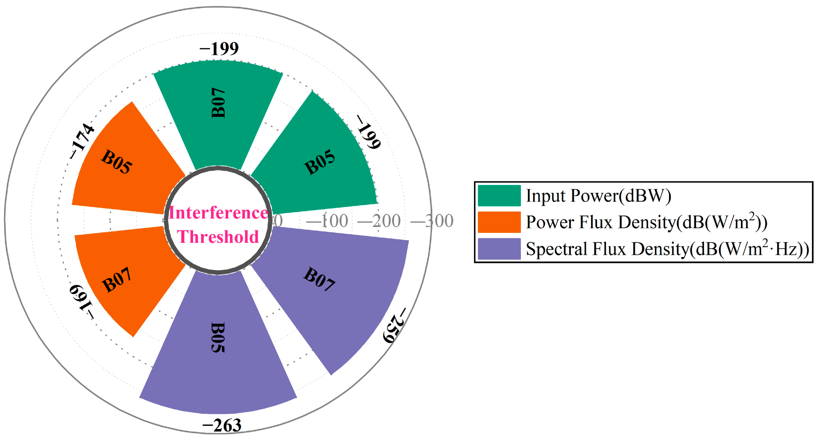
3.2. Analysis Result
- Frequency: The upper and lower limits of each IMT-2000 base station working frequency band are selected as the analysis main frequency points, including multiple frequencies such as 1880 MHz, 1885 MHz, 1900.4 MHz, 1905 MHz, 1910.4 MHz, 1920 MHz, 2010 MHz, and 2025 MHz under CMCC and 2130.1 MHz, 2131.1 MHz, 2135.1 MHz, 2136.1 MHz, and 2155.1 MHz under CUCC.
- Time percentage: Five kinds of time probability, including 1%, 10%, 50%, 90%, and 99%.
- FAST receiving antenna zenith angle: 0°, 10°, 20°, 30°, and 40°.
- Antenna radiation direction: towards the base station transmitting antenna and away from the base station transmitting antenna.
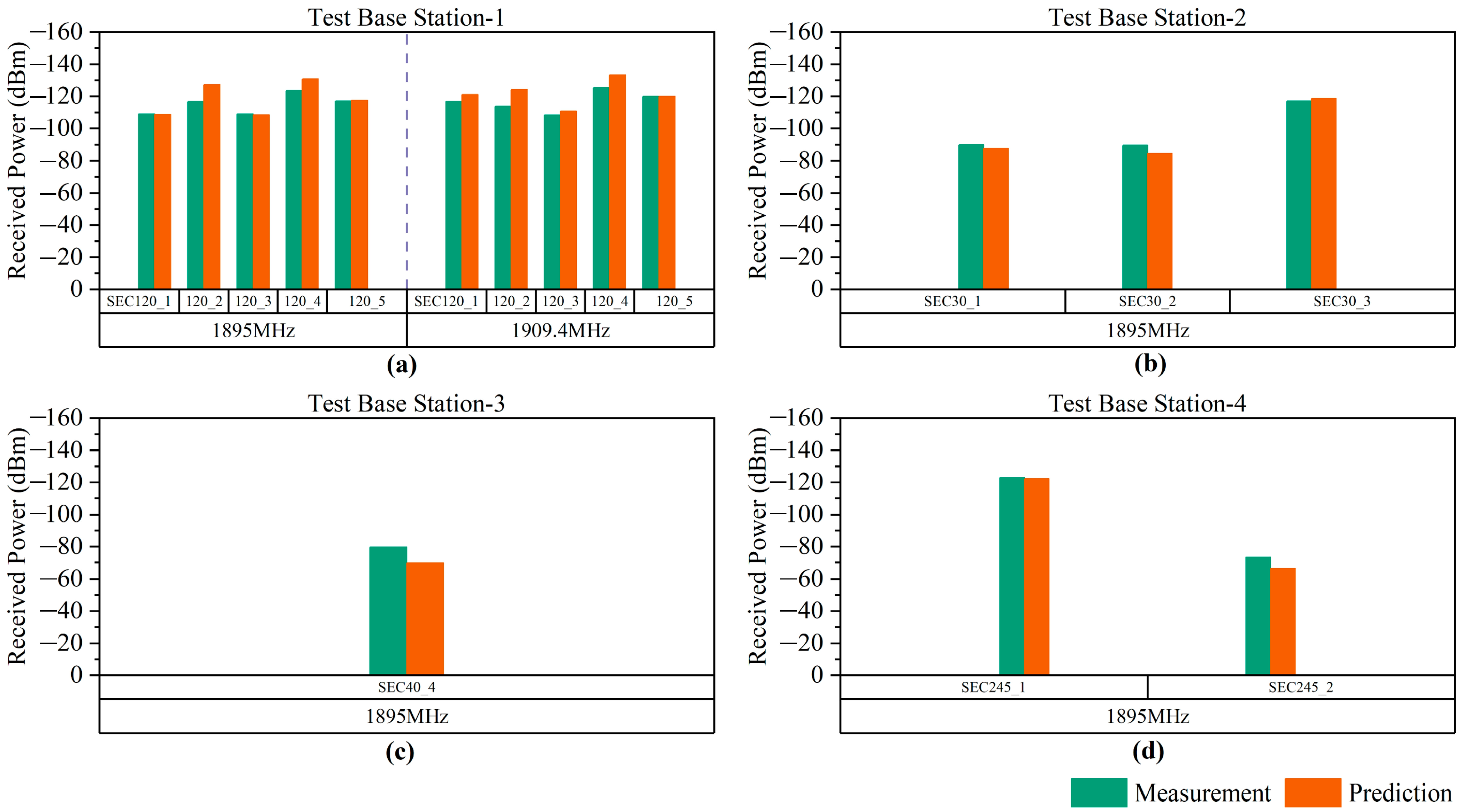
3.3. Result Validation
4. Conclusions
Author Contributions
Funding
Institutional Review Board Statement
Informed Consent Statement
Data Availability Statement
Acknowledgments
Conflicts of Interest
References
- Dalela, C.; Prasad, M.V.S.N.; Dalela, P.K.; Saraf, R. Analysis of WiMAX radio measurements and comparison with some models over dense urban western india at 2.3 GHz. IEEE Antennas Wirel. Propag. Lett. 2011, 10, 730–733. [Google Scholar] [CrossRef]
- Wei, M.; Liang, G.G.; Shi, D.; Gao, Y.G. Base station electromagnetic simulation using ray-tracing method. In Proceedings of the 2012 6th Asia-Pacific Conference on Environmental Electromagnetics (CEEM), Shanghai, China, 6–9 November 2012; pp. 360–362. [Google Scholar]
- Yin, J.N.; Jiang, P.; Yao, R. Pose optimization of the FAST feed support system based on the new feed cabin mechanism. Sci. China Phys. Mech. Astron. 2023, 66, 182–191. [Google Scholar] [CrossRef]
- Nan, R.D.; Li, D.; Jin, C.J.; Wang, Q.M.; Zhu, L.C.; Zhu, W.B.; Zhang, H.Y.; Yue, Y.L.; Qian, L. The Five-hundred-meter Aperture Spherical radio Telescope (FAST) project. Int. J. Mod. Phys. D 2011, 20, 989–1024. [Google Scholar] [CrossRef]
- Lin, L.; Zhang, C.F.; Wang, P.; Gao, H.; Guan, X.; Han, J.L.; Jiang, J.C.; Jiang, P.; Lee, K.J.; Li, D.; et al. No pulsed radio emission during a bursting phase of a galactic magnetar. Nature 2020, 587, 63–65. [Google Scholar] [CrossRef] [PubMed]
- Qian, L.; Yao, R.; Sun, J.H.; Xu, J.L.; Pan, Z.C.; Jiang, P. FAST: Its scientific achievements and prospects. Innovation 2020, 1, 100053. [Google Scholar] [CrossRef] [PubMed]
- Sitompul, P.P.; Manik, T.; Batubara, M.; Suhandi, B. Radio frequency interference measurements for a radio astronomy observatory site in Indonesia. Aerospace 2021, 8, 51. [Google Scholar] [CrossRef]
- Zhang, H.Y.; Yao, R.; Hu, H.; Huang, S.J. RFI mitigation on FAST feed cabin. In Proceedings of the 2018 IEEE Global Conference on Signal and Information Processing (GlobalSIP), Anaheim, CA, USA, 26–28 November 2018; pp. 1091–1094. [Google Scholar] [CrossRef]
- Zhang, H.Y.; Wu, M.C.; Yue, Y.L.; Gan, H.Q.; Hu, H.; Huang, S.J.; Sun, J.H.; Peng, B.; Nan, R.D.; FAST Collaboration. RFI measurements and mitigation for FAST. Res. Astron. Astrophys. 2020, 20, 075. [Google Scholar] [CrossRef]
- Wang, Y.; Zhang, H.Y.; Hu, H.; Huang, S.J.; Zhu, W.W.; Zhi, G.P.; Zhang, T.; Fan, Z.C.; Yang, L. Satellite RFI mitigation on FAST. Res. Astron. Astrophys. 2021, 21, 018. [Google Scholar] [CrossRef]
- Wang, J.; Shi, Y.F.; Yang, C.; Ji, S.Y.; Su, H.B. Research on fading characteristics of ultrahigh frequency signals in karst landform around radio quiet zone of FAST. Radio Sci. 2020, 55, e2019RS007048. [Google Scholar] [CrossRef]
- Wang, J.; Zhao, Y.B.; Shi, Y.F.; Yang, C.; Hao, Y.L.; Sun, J.M. The electromagnetic compatibility between FAST and public mobile communication stations and its cognitive using frequency strategy. Res. Astron. Astrophys. 2022, 22, 125005. [Google Scholar] [CrossRef]
- Liu, P.; Wang, P.; Li, D.; Zhang, J.; Zhang, L.; Zhang, C.M.; Zhu, W.W.; Yue, D.L.; Dai, S. FAST 19-beam drift-scan pulsar survey simulation. Prog. Astron. 2018, 36, 173–188. [Google Scholar] [CrossRef]
- Nan, R.D.; Zhang, H.Y.; Zhang, Y.; Yang, L.; Cai, W.J.; Liu, N.; Xie, J.T.; Zhang, S.X. Construction progress of the FAST project. Chin. Astron. Astrophys. 2017, 41, 293–301. [Google Scholar] [CrossRef]
- Internatinal Telecommunication Union. Rec. ITU-R RA.769-2 ITU—R Protection Criteria Used for Radio Astronomical Measurements; ITU: Geneva, Switzerland, 2020. [Google Scholar]
- Zhang, Y.G.; Zhang, W.F.; Zhang, S.H. Overview of the development of 1~6 G mobile communication systems. China Comput. Commun. 2020, 32, 157–160. [Google Scholar]
- Internatinal Telecommunication Union. Rec. ITU-R P.452-17 ITU—R Prediction Procedure for the Evaluation of Interference between Stations on the Surface of the Earth at Frequencies above about 0.1 GHz; ITU: Geneva, Switzerland, 2021. [Google Scholar]
- Internatinal Telecommunication Union. Rec. ITU-R RA.1031-3 ITU—R Protection of the Radio Astronomy Service in Frequency Bands Shared with Active Services; ITU: Geneva, Switzerland, 2021. [Google Scholar]
- Internatinal Telecommunication Union. Rec. ITU-R P.2001-4 ITU—R A General Purpose Wide-Range Terrestrial Propagation Model in the Frequency Range 30 MHz to 50 GHz; ITU: Geneva, Switzerland, 2021. [Google Scholar]
- Huang, S.J.; Zhang, H.Y.; Hu, H. Study on electromagnetic compatibility between FAST and mobile base stations. J. Deep. Space Explor. 2020, 7, 144–151. [Google Scholar] [CrossRef]


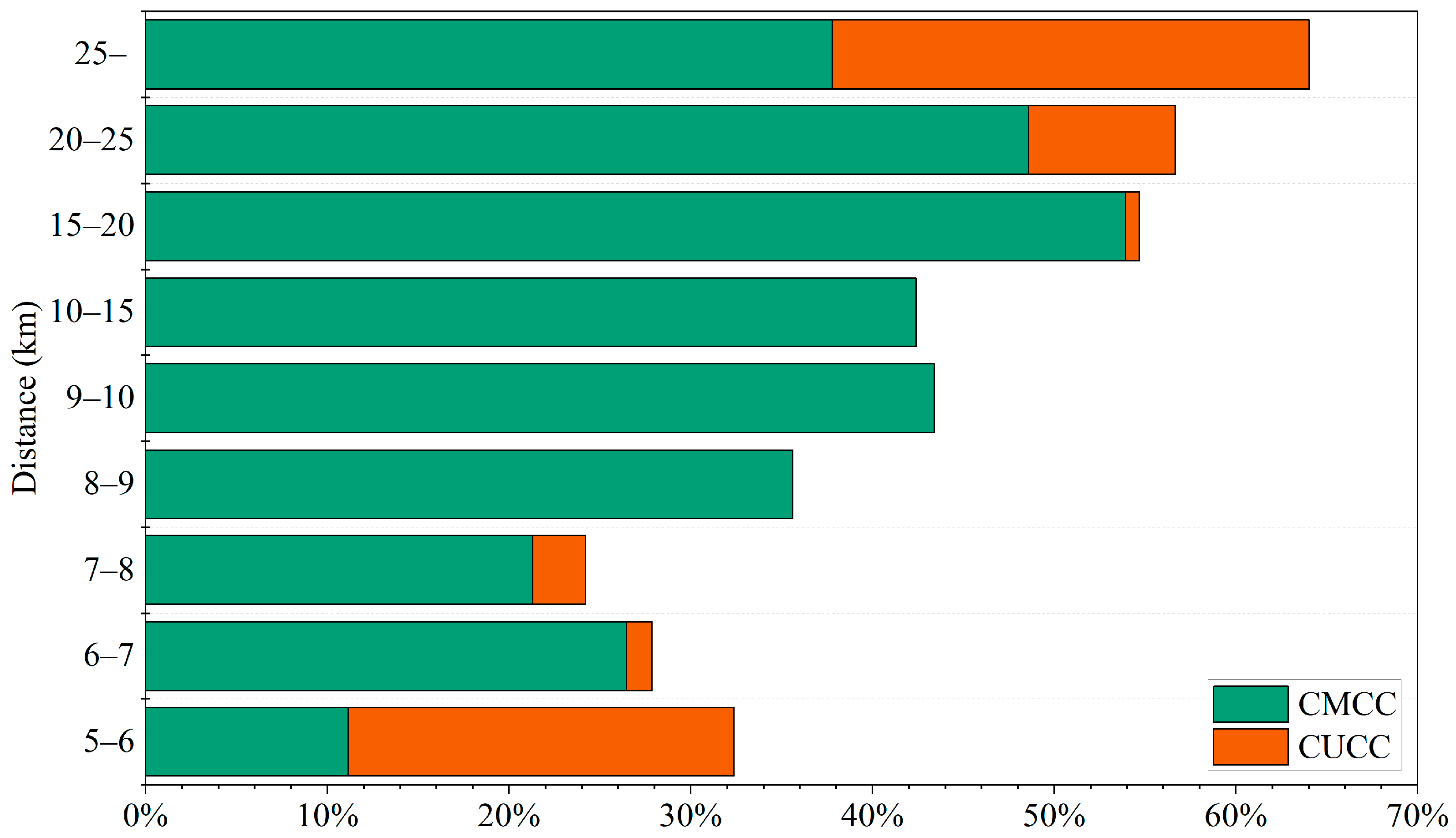
| Receiver | CMCC | CUCC | Total Data | Proportion |
|---|---|---|---|---|
| B05 (1100–1900 MHz) | 25,298 | - | 45,945 | 55.06% |
| B07 (2000–3000 MHz) | 400 | 8823 | 16,470 | 56.00% |
| Total | 25,698 | 8823 | 62,415 | 55.31% |
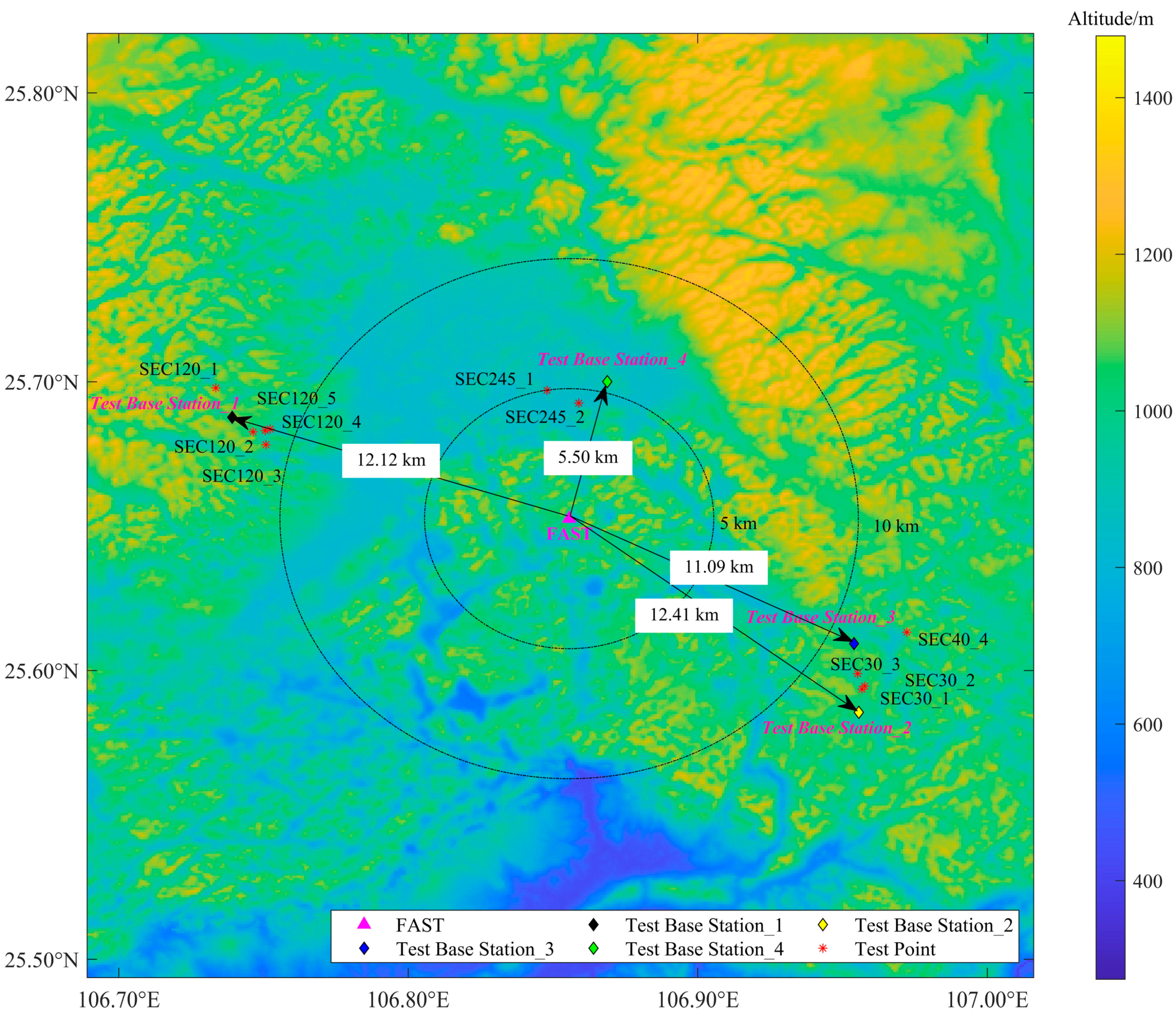
| Test Station Parameters | Receiver Point Parameters | |||||||
|---|---|---|---|---|---|---|---|---|
| Test Station | Location | Altitude (m) | Antenna Height (m) | Distance from FAST (km) | Frequency (MHz) | Transmit Power (W) | Antenna Height (m) | Path Distance (km) |
| 1 | (106.74° E, 25.69° N) | 1150 | 15 | 12.12 | 1895/1909.4 | 20 | 4 | 0.9–2.1 |
| 2 | (106.96° E, 25.59° N) | 1035 | 12 | 12.41 | 1895 | |||
| 3 | (106.95° E, 25.61° N) | 960 | 21 | 11.09 | 1895 | |||
| 4 | (106.87° E, 25.70° N) | 930 | 15 | 5.50 | 1895 | |||
| Test Base Station | ME (dB) | MD (dB) | SD (dB) |
|---|---|---|---|
| 1 | −4.23 | 4.49 | 6.05 |
| 2 | 1.93 | 2.87 | 3.23 |
| 3 | 10.00 | 10.00 | 10.00 |
| 4 | 3.65 | 3.65 | 4.82 |
| Total | −1.20 | 4.43 | 5.83 |
Disclaimer/Publisher’s Note: The statements, opinions and data contained in all publications are solely those of the individual author(s) and contributor(s) and not of MDPI and/or the editor(s). MDPI and/or the editor(s) disclaim responsibility for any injury to people or property resulting from any ideas, methods, instructions or products referred to in the content. |
© 2023 by the authors. Licensee MDPI, Basel, Switzerland. This article is an open access article distributed under the terms and conditions of the Creative Commons Attribution (CC BY) license (https://creativecommons.org/licenses/by/4.0/).
Share and Cite
Wang, J.; Zhao, Y.; Yang, C.; Shi, Y.; Hao, Y.; Zhang, H.; Sun, J.; Luo, D. The Analysis and Verification of IMT-2000 Base Station Interference Characteristics in the FAST Radio Quiet Zone. Universe 2023, 9, 248. https://doi.org/10.3390/universe9060248
Wang J, Zhao Y, Yang C, Shi Y, Hao Y, Zhang H, Sun J, Luo D. The Analysis and Verification of IMT-2000 Base Station Interference Characteristics in the FAST Radio Quiet Zone. Universe. 2023; 9(6):248. https://doi.org/10.3390/universe9060248
Chicago/Turabian StyleWang, Jian, Yibo Zhao, Cheng Yang, Yafei Shi, Yulong Hao, Haiyan Zhang, Jianmin Sun, and Dingling Luo. 2023. "The Analysis and Verification of IMT-2000 Base Station Interference Characteristics in the FAST Radio Quiet Zone" Universe 9, no. 6: 248. https://doi.org/10.3390/universe9060248