Article

Outage Performance of Power Beacon-Aided Multi-Hop Cooperative Cognitive Radio Protocol Under Constraint of Interference and Hardware Noises

1
Faculty of Electrical and Electronics Engineering, Ho Chi Minh City University of Technology and Education, Ho Chi Minh City 700000, Vietnam
2
Faculty of Electronics Technology, Industrial University of Ho Chi Minh City, Ho Chi Minh City 700000, Vietnam
3
Department of Telecommunications, Posts and Telecommunications Institute of Technology, Ho Chi Minh City 700000, Vietnam
4
Faculty of Electrical and Electronics Engineering, Ho Chi Minh City University of Food Industry, Ho Chi Minh City 700000, Vietnam
*
Author to whom correspondence should be addressed.
Electronics 2020, 9(6), 1054; https://doi.org/10.3390/electronics9061054
Submission received: 30 May 2020 / Revised: 15 June 2020 / Accepted: 23 June 2020 / Published: 26 June 2020
(This article belongs to the Special Issue RF Energy Harvesting and Wireless Power Transfer)

Abstract

:
In this paper, we evaluate end-to-end outage probability of a multi-hop decode-and-forward relaying protocol in underlay cognitive radio network. In the proposed protocol, named COOP, secondary nodes including source and relays have to harvest radio-frequency energy from multiple secondary power beacons, and adjust their transmit power, follows a pre-determined interference threshold given by multiple primary users. To enhance the outage performance for the secondary network under an joint constraint of the interference threshold, Rayleigh fading channel and hardware noises caused by imperfect transceiver hardware, the secondary relays on the source-destination path cooperate to forward the source data to the destination. Particularly, they attempt to receive the source data from their previous nodes, and forward it to the secondary destination if requested. Moreover, whenever the destination cannot receive the source data successfully, a successful relay that has the shortest distance to the destination is selected for retransmission. Due to usage of the cooperative transmission, the proposed COOP protocol obtains better performance, as compared with the corresponding multi-hop relaying one (denoted DIRECT) which only uses direct transmission at each hop. We evaluate the outage performance of COOP and DIRECT via both simulation and theory. The obtained results present a significant performance enhancement, as comparing COOP with DIRECT.

Graphical Abstract

1. Introduction

Radio frequency energy harvesting (RF-EH) [1,2,3,4,5] is a new and promising technique for wireless communication applications in future when the number of wireless devices exponentially increases. In addition, RF-EH also allows a transmitter to simultaneously send energy and information to its intended receivers via wireless signals. As proposed in Reference [6], a relay node can receive both data and energy from a source by allocating a fraction of the received signal power for EH, and remaining one for data transmission. This method is named as power-splitting (PS) RF-EH, and is widely applied in various wireless relaying networks (see References [6,7,8,9,10] and references therein). Different with PS RF-EH, the relay node using time-splitting (TS) RF-EH [11,12,13,14,15] has to harvest energy before the source-relay transmission is performed. More particular, the EH and information transfer phases in TS RF-EH are separated. References [16,17,18] proposed hybrid RF-EH protocols which combined the TS and PS techniques to further enhance the system performance for wireless relaying protocols, in terms of throughput, spectral efficiency and EH efficiency. The authors of References [19,20] considers role of co-channel interference, especially in viewpoint of RF-EH. As analyzed in References [19,20], co-channel interference from ambient sources can support the green energy as well as prolong lifetime for wireless communication systems. To support the wireless energy for a large number of wireless nodes in a certain area, the published literature [21,22,23,24,25] has proposed power beacon (PB)-aided RF-EH protocols. Particularly, in Reference [21], the authors solved a joint time and energy allocation problem for the PB-aided RF-EH network. Reference [22] evaluated the performance of PB-assisted millimeter wave ad-hoc networks, where the transmitter harvests energy from all the low-cost PBs for transmitting its data to an intended receiver. The author of Reference [23] analyzed throughput of the RF-EH network with the help of multiple PBs over Nakagami-m fading channels. Reference [24] studied a non-uniform deployment of PBs, while the authors of Reference [25] investigated deployment of distributed antennas of PB in the RF-EH network.
Until now, almost published works related to performance analysis of the RF-EH networks have mainly focused on single-hop and dual-hop protocols. There has been several literature considering multi-hop relaying ones, for example, References [26,27,28,29,30]. The authors in Reference [26] considered RF-EH decode-and-forward (DF) and amplify-and-forward (AF) relaying protocols using the TS and PS techniques. The results obtained in Reference [26] presented that for network coverage extension, TS can obtain better performance than PS, and DF provides more hops than AF. Reference [27] proposed a multi-hop AF relaying protocol operating on co-channel interference environments, where all nodes on a source-destination path are capable of harvesting energy from nearby interference sources. Reference [28] studied the e2e throughput of multi-hop AF networks with RF-EH. The results obtained in Reference [28] showed that the PS technique outperforms the TS technique at high signal-to-noise ratio (SNR). In Reference [29], RF-EH based multi-hop protocols with DF relays were considered. In addition, the end-to-end (e2e) throughput of the TS, PS and hybrid TS/PS methods were studied and optimized in Reference [29]. In Reference [30], a multi-hop RF-EH wireless sensor networks (WSNs) employing non-orthogonal multiple access and cooperative jamming methods were proposed. Moreover, relay and jammer nodes in Reference [30] are powered by power transfer stations deployed in the network.
Cognitive radio (CR) [31] was proposed to solve spectrum-scarcity issue as well as inefficient spectrum usage. In this technique, primary users (or licensed users) can share their licensed bands to secondary users (or unlicensed users) [32,33,34]. Underlay spectrum sharing (USS) [35,36,37] is one of the efficient CR techniques, where the primary and secondary users can use the same bands. However, the secondary transmitters operating on the USS mode must reduce their transmit power to satisfy a certain interference constraint required by the primary network. Recently, RF-EH based cognitive relaying protocols have gained much attention of researchers. References [38,39] proposed PB-aided cognitive multi-hop DF relaying protocols employing the USS technique. The authors of References [40,41] evaluated the e2e performance of cluster-based multi-hop USS protocols with the RF-EH DF relays and relay selection methods at each cluster. The authors of Reference [42] evaluated the outage performance of partial and opportunistic relay selection methods for PB-assisted dual-hop CR WSNs under impact of hardware imperfection. Reference [43] considered throughput optimization for multi-channel CR mechanism employing hybrid overlay/underlay spectrum sharing with RF-EH.
This paper proposes a PB-aided multi-hop cooperative cognitive radio protocol (denoted by COOP) to mitigate joint impact of fading environments, interference level constrained by the primary network and imperfection of transceiver hardware. Hence, the first main objective is to improve the performance of the secondary network by using multi-hop cooperative transmission, as compared with the conventional one (denoted by DIRECT) in which the direct transmission is used at each hop to forward the source data to the destination. Unlike DIRECT, the secondary relays in COOP can receive the source data from their previous nodes, and attempt to decode it. Moreover, whenever the destination cannot correctly receive the data, it requires a retransmission from the successful and nearest relay. Because the receivers in COOP can exploit the spatial diversity, COOP obtains better performance than DIRECT. Next, the second objective of this paper is to derive an exact closed-form expression to evaluate the performance of COOP (and DIRECT). Because the derived expression is easy-to-compute, it can be easily used by designers for optimizing the considered system.
Next, we present the main difference between our work and the existing ones. Unlike References [38,39], a generalized system model with multiple power beacons and multiple primary users is studied. Unlike References [23,42], our proposed protocol considers the multi-hop relaying networks employing cooperative communication [44]. The most related to this paper is our previous work [45] which also proposes the PB-aided multi-hop cooperative transmission protocol to enhance the e2e OP. However, different to Reference [45], we consider the CR environment in which the secondary transmitters can access the licensed bands at the same time with the primary users, follows the USS approach. Moreover, while transceiver hardware of all the terminals in Reference [45] is assumed to be perfect, this paper investigates impact of hardware impairments (HIs) on the OP performance.
In the following, we summarize the contribution obtained in this paper:
  • Cooperation-based multi-hop DF relaying protocol is applied for the underlay CR networks to mitigate the joint impact of the interference constraint and HIs.
  • From the energy harvested from multiple PBs and from the maximal interference threshold given by multiple primary users, we formulate transmit power of the secondary transmitters including the secondary source and relay nodes.
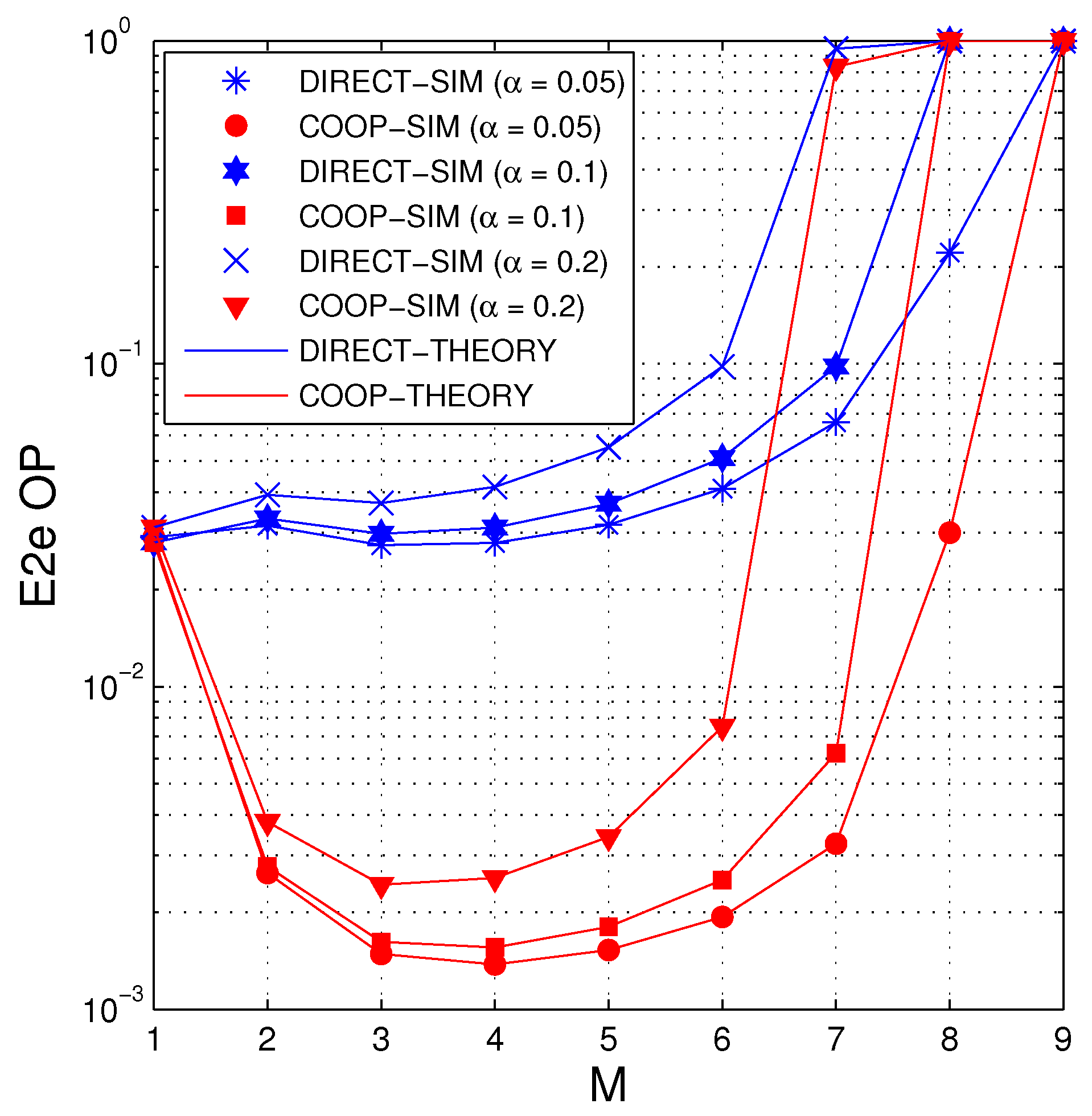
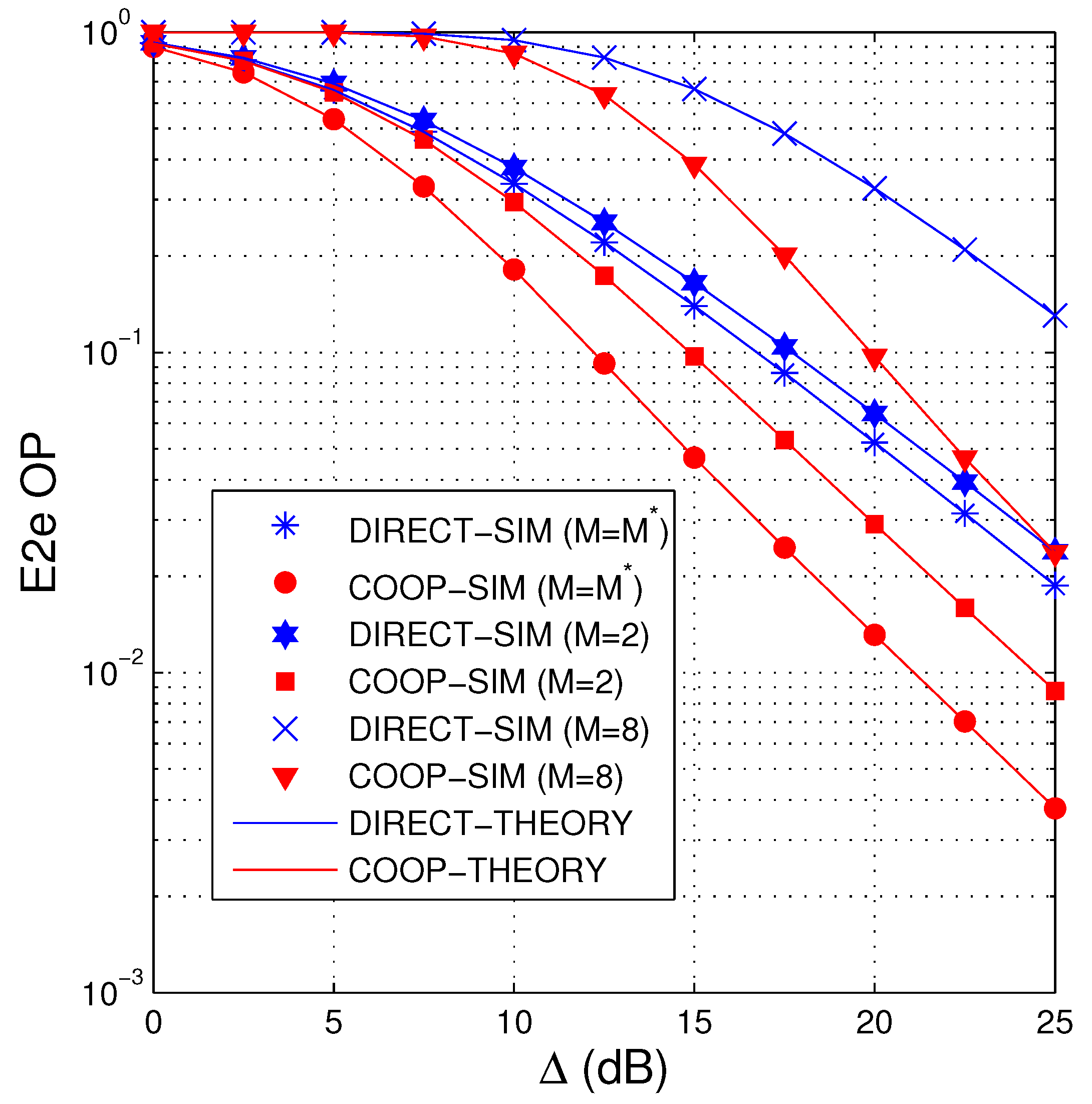
  • We derive an exact recursive expression of the e2e OP for the proposed protocol over Rayleigh fading channels. We also realize Monte-Carlo based computer simulations to verify the theory. Relying on the derived expressions, optimization problems such as optimal number of hops and optimal fraction of total communication time used for the EH phases, are also performed.
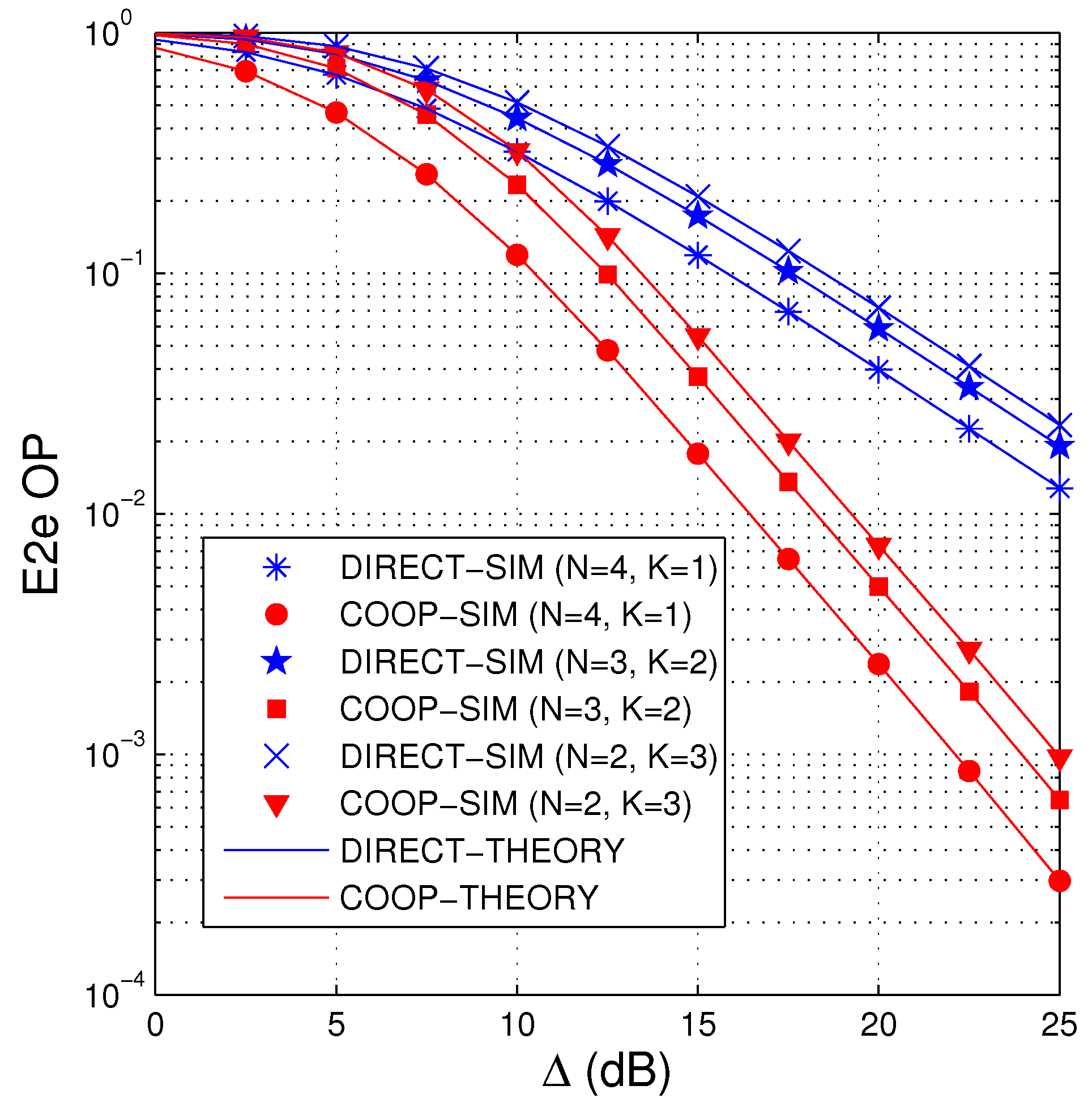
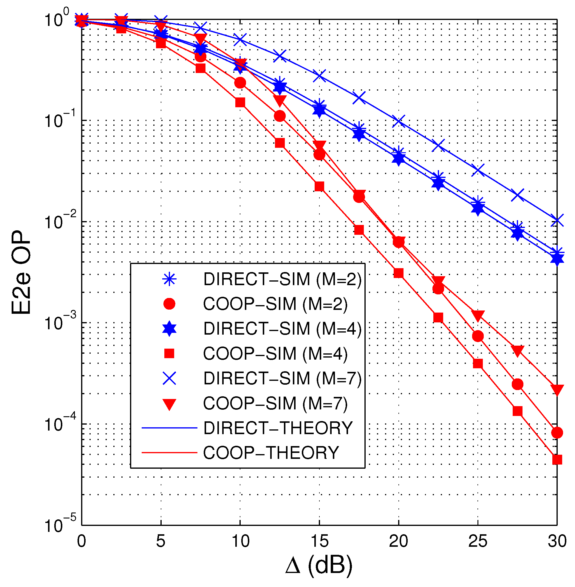
  • The results presented that the COOP protocol outperforms the DIRECT one. In addition, the system parameters such as number of PBs, number of primary users, number of hops, fraction of time allocated for the EH phases, and total HI level significantly effect on the e2e OP.
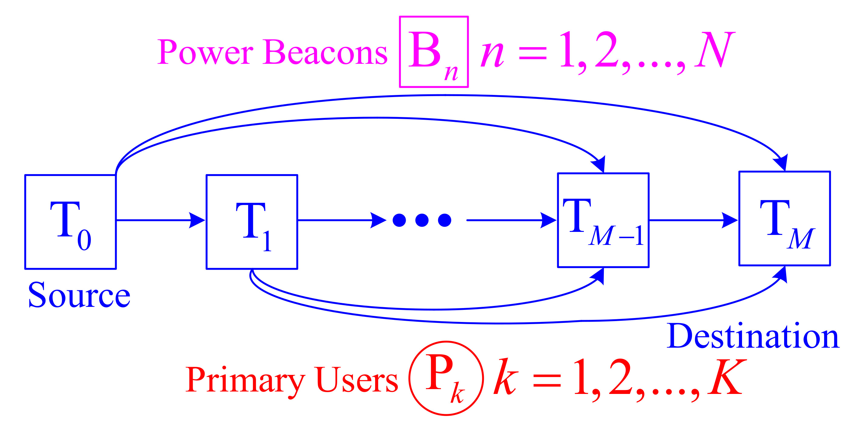
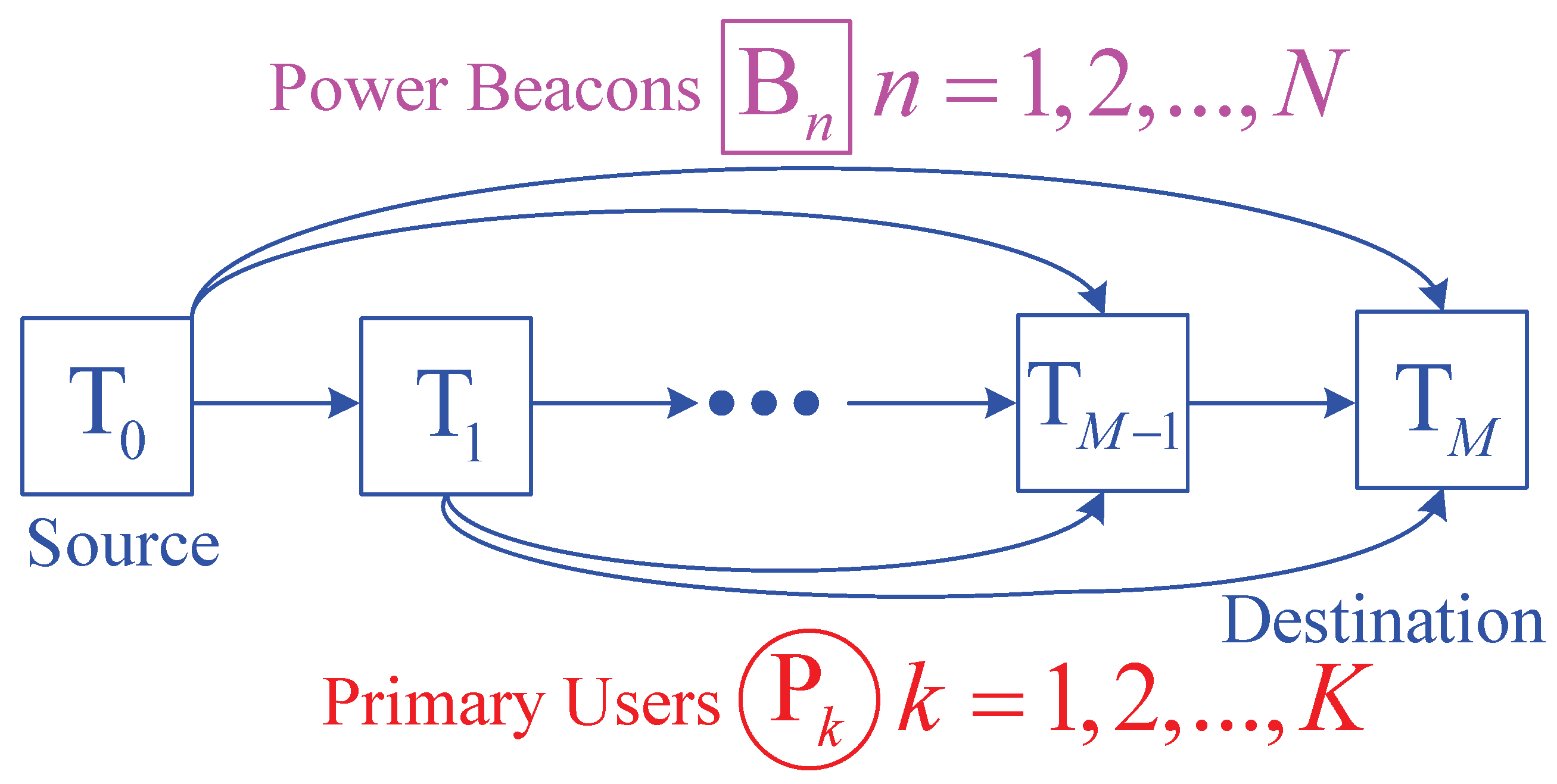
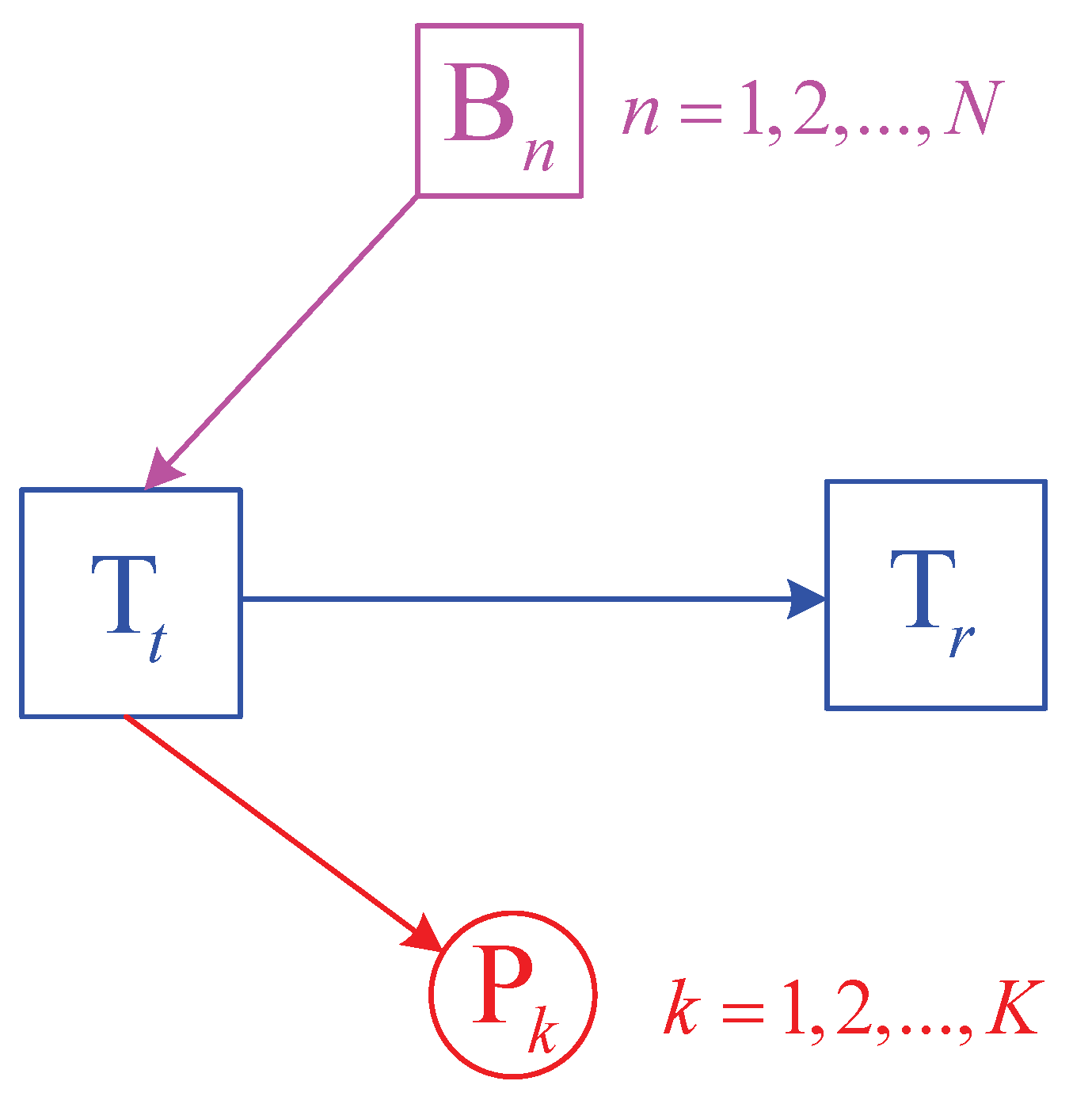
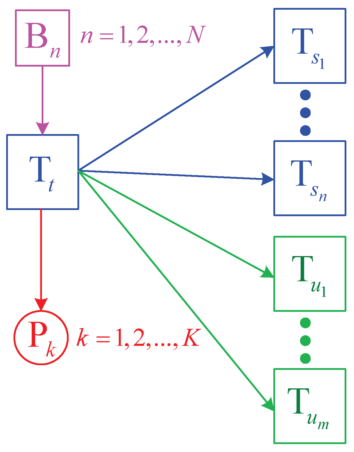
The remainder of this paper is structured as follows. The system model of COOP and DIRECT is described in Section 2. Section 3 analyzes the e2e OP performance of COOP and DIRECT over Rayleigh fading channel. The simulation and theoretical results are presented in Section 4 to verify each other. Finally, conclusions and discussions are shown in Section 5.

2. System Model

In Figure 1, a secondary source T 0 attempts to send its data to a secondary destination T M via the assistance of secondary relays denoted by T 1 , T 2 , ..., T M 1 . Let d T a , T b denote link distance between T a and T b , where a , b 0 , 1 , , M . The relays are numbered, follows the distance between themselves and the destination, that is, d T a , T M is higher than d T b , T M if a < b . The secondary source and relay nodes have to harvest wireless energy from N power beacons (denoted by B 1 , B 2 , ..., B N ) deployed in the secondary network, and use the harvested energy to transmit the source data to the destination [38,39,42]. Employing the USS method, the secondary transmitters must adapt their transmit power to satisfy a maximal interference constraint given by K primary users denoted by P 1 , P 2 , ..., P K . All the nodes including T m , B n and P k are single-antenna wireless devices, where m = 0 , 1 , , M , n = 1 , 2 , , N and k = 1 , 2 , , K . Due to usage of half-duplex mode, the T 0 T M data transmission is split into orthogonal time slots.
We denote h X , Y and γ X , Y as channel coefficient and channel gain between the nodes X and Y, respectively, where γ X , Y = | h X , Y | 2 and X , Y T m , B n , P k . Assume that all the channels are Rayleigh fading; hence cumulative distribution function (CDF) and probability density function (PDF) of γ X , Y can be expressed as (see Reference [46])
F γ X , Y = 1 exp λ X , Y x , f γ X , Y = λ X , Y exp λ X , Y x ,
where F γ X , Y . and f γ X , Y . denote CDF and PDF of random variable (RV) γ X , Y , respectively, λ X , Y = d X , Y β [44], d X , Y is the X-Y link distance, and β is path-loss exponent.
Now, we describe the operation of COOP:
Let L denote a maximum delay time of each T 0 T M data transmission, and each time slot is equally allocated by τ = L / M . At the first time slot, T 0 spends a duration of α τ for harvesting the energy from the power beacons, where α 0 < α 1 is a system parameter. Then, the energy obtained at T 0 can be computed, similar to References [23,42] as
E 0 = μ α τ Q B n = 1 N γ B n , T 0 ,
where μ 0 μ 1 is a conversion efficiency, and Q B is transmit power of all the power beacons.
Because the time used for the data transmission is 1 α τ , the transmit power of T 0 can be formulated as
Q 0 = E 0 1 α τ = θ Q B X B , T 0 sum ,
where θ = μ α / 1 α , X B , T 0 sum = n = 1 N γ B n , T 0 .
Moreover, due to the interference constraint, the transmit power of T 0 must satisfy the following condition (see Reference [42]):
Q 0 I th 1 + κ P 2 max k = 1 , 2 , , K γ T 0 , P k = I th 1 + κ P 2 X P , T 0 max ,
where κ P 2 is total impairment level caused by the hardware imperfection at T 0 and P k for all k [42,47], I th is maximum interference threshold, and X P , T 0 max = max k = 1 , 2 , , K γ T 0 , P k .
From (3) and (4), the maximum transmit power of T 0 can be formulated as
Q 0 = min θ Q B X B , T 0 sum , I th 1 + κ P 2 X P , T 0 max = θ Q B min X B , T 0 sum , I P X P , T 0 max ,
where
I P = I th 1 + κ P 2 θ Q B .
Now, we consider the data transmission phase at the first time slot in which T 0 sends its data to T M , which is also received by all the relays. Under the impact of HIs, the received signal at T m due to the transmission of T 0 is written as
y 0 , m = Q 0 h T 0 , T m x S + η T 0 , T m + n m ,
where x S is the source signal, η T 0 , T m is noise caused by HIs at T 0 and T m , n m is additive Gaussian noise at T m . For ease of presentation, the additive Gaussian noise at all the receivers are Gaussian RVs with zero-mean and variance of σ 0 2 . Similar to References [42,47], η T 0 , T m is modeled as a zero-mean Gaussian RV whose variance is κ S 2 .
From (5) and (7), the instantaneous SNR of the T 0 T m link can be obtained as
ψ 0 , m = Q 0 γ T 0 , T m κ S 2 Q 0 γ T 0 , T m + σ 0 2 = θ Δ min X B , T 0 sum , I P / X P , T 0 max γ T 0 , T m κ S 2 θ Δ min X B , T 0 sum , I P / X P , T 0 max γ T 0 , T m + 1 = θ Δ Y 0 γ T 0 , T m κ S 2 θ Δ Y 0 γ T 0 , T m + 1 ,
where Δ = Q B / σ 0 2 and Y 0 = min X B , T 0 sum , I P / X P , T 0 max . Then, the instantaneous channel capacity of the T 0 T m link is formulated from (8) as
C 0 , m = 1 α τ log 2 1 + ψ 0 , m = 1 α τ log 2 1 + θ Δ Y 0 γ T 0 , T m κ S 2 θ Δ Y 0 γ T 0 , T m + 1 .
At the end of the first time slot, the destination and all the relays attempt to decode the source data. If the decoding status of T M is successful, the data transmission is also successful. Otherwise, T M needs a retransmission from one of the successful relays. Hence, if there is no successful relay, the source data is dropped. Otherwise, the successful one which has the shortest distance to T M forwards the source data to the destination [45]. Furthermore, the selected relay repeats the operation that the source did.
Generally, we consider the transmission at the u th time slot, where 1 u M . Here, we assume that at the u 1 th time slot, T M fails to decode the source data, and there exists at least one successful relay. Therefore, let us denote T t u as the selected relay, where t u 1 , 2 , , M 1 . Similar to T 0 , T t u harvests the wireless energy (during α τ ), adjusts its transmit power, and transmits the source data to T M and the relays between T t u and T M (during 1 α τ ). Similarly, if T M correctly decodes the data, the transmission is completed. Otherwise, let us denote D u as set of the successful relays, D u = T v 1 , T v 2 , , T v n u , where 0 n u M 1 , t u < v 1 < v 2 < < v n u M 1 . Also, we denote G u as set of the unsuccessful nodes, that is, G u = T z 1 , T z 2 , , T z m u , T M , 0 m u M 1 , t u < z 1 < z 2 < < z m u M 1 .
For example, if D u is empty, that is, D u = ϕ or n u = 0 , the source data is dropped at this time slot. Otherwise, the relay which belongs to D u , and is nearest to T M is chosen for retransmitting the source data to T M at the u + 1 th time slot. Indeed, the selected node is T v n u , and it will repeat the transmission process as T t u did.
Remark 1.
In References [38,39,42], the EH phase and the data transfer phases are separated, that is, all the transmitters first harvest the wireless energy from PBs, and then they will wait until they can transmit the data to the next node. On the contrary, the source and relay nodes in COOP and DIRECT only harvest energy before their data transmission.

3. Performance Analysis

This section exactly calculates the e2e OP of COOP and DIRECT.

3.1. Mathematical Preliminaries

Let us consider the point-to-point transmission between the transmitter T t and the receiver T r as illustrated in Figure 2, where t , r 0 , 1 , , M . Similar to (5) and (9), the transmit power of T t and the instantaneous SNR of the T t T r link can be formulated, respectively as
Q t = θ Q B min X B , T t sum , I P X P , T t max ,
C t , r = 1 α τ log 2 1 + θ Δ Y t γ T t , T r κ S 2 θ Δ Υ t γ T t , T r + 1 ,
where X B , T t sum = n = 1 N γ B n , T t , X P , T t max = max k = 1 , 2 , , K γ T t , P k and Y t = min X B , T t sum , I P / X P , T t max .
Assume that all power beacons nodes are in a cluster [23]; the link distances and the channel parameters can be assumed to be identical, that is, d B n , T t = d B , T t , λ B n , T t = λ B , T t for all n and t. Similarly, when the primary users are close together [42], we can assume d P k , T t = d P , T t , λ P k , T t = λ P , T t for all k and t. Hence, CDF of X B , T t sum can be expressed as (see Reference [48]):
F X B , T t sum x = 1 exp λ B , T t x p = 0 N 1 λ B , T t p x p p ! ,
Next, CDF of X P , T t max can be given as
F X P , T t max x = Pr max k = 1 , 2 , , K γ T t , P k < x = k = 1 K Pr γ T t , P k < x = 1 exp λ P , T t x K = 1 q = 1 K 1 q + 1 C K q exp q λ P , T t x ,
where C K q = K ! q ! K q ! is a binomial coefficient.
Because Y t = min X B , T t sum , I P / X P , T t max , CDF of Y t can be obtained as
F Y t x = Pr min X B , T t sum , I P / X P , T t max < x = 1 Pr X B , T t sum x Pr X P , T t max I P x = 1 1 F X B , T t sum x F X P , T t max I P x .
Substituting (12) and (13) into (14), which yields
F Y t x = 1 p = 0 N 1 λ B , T t p p ! x p exp λ B , T t x + p = 0 N 1 q = 1 K 1 q + 1 p ! C K q λ B , T t p x p exp λ B , T t x exp q λ P , T t I P x .

3.2. Point-to-Point Data Transmission

This sub-section evaluates the outage probability of a point-to-point link between T t and T r , as shown in Figure 2. At first, OP of the T t T r link is defined as probability that the instantaneous channel capacity is below a target rate, that is, C th . Using (11), we obtain (16) as
O P T t , T r = Pr C t , r < C th = Pr 1 κ 2 ρ th θ Δ Y t γ T t , T r < ρ th ,
where
ρ th = 2 C t h 1 α τ 1 .
As observed in (16), if 1 κ 2 ρ th 0 , then O P T t , T r = 1 . Let us consider the case where 1 κ 2 ρ th > 0 , we can rewrite (16) as in (18):
O P T t , T r = Pr Y t γ T t , T r < ϕ = 0 + F Y t ϕ x f γ T t , T r x d x ,
where
ϕ = ρ th 1 κ 2 ρ th θ Δ .
Substituting (15) and PDF f γ T t , T r x given in (1) into (18), which yields
O P T t , T r = 1 p = 0 N 1 λ B , T t ϕ p λ T t , T r p ! 0 + 1 x p exp λ B , T t ϕ x exp λ T t , T r x d x + p = 0 N 1 q = 1 K 1 q + 1 p ! C K q λ B , T t ϕ p λ T t , T r 0 + 1 x p exp λ B , T t ϕ x exp φ 1 x d x ,
where
φ 1 = λ T t , T r + q λ P , T t I P ϕ .
Applying (Reference [49], Equation (3.478.4)) for calculating the integrals in (20), which yields
O P T t , T r = 1 p = 0 N 1 2 p ! λ B , T t λ T t , T r ϕ p + 1 2 K 1 p 2 λ B , T t λ T t , T r ϕ + p = 0 N 1 q = 1 K 1 q + 1 2 C K q p ! λ B , T t ϕ p + 1 2 λ T t , T r φ 1 p 1 2 K 1 p 2 λ B , T t ϕ φ 1 ,
where K 1 p . is modified Bessel function of the second kind with order of 1 p [49].

3.3. Point-to-Multi-Point Data Transmission

As presented in Figure 3, the transmitter T t transmits its data to multiple receivers denoted by T s 1 , , T s n , T u 1 , , T u m . Assume that after decoding the data of T t , the receivers T s 1 , T s 2 ,..., T s n are successful nodes, and T u 1 , T u 2 ,..., T u m are unsuccessful nodes, where 0 n M , 1 m M . For ease of presentation, we denote D = T s 1 , T s 2 , , T s n , G = T u 1 , T u 2 , , T u m . In addition, we assume that the destination T M belongs to G. Next, we can formulate OP in this case as
O P T t , D , G = Pr C t , s 1 C th , , C t , s n C th , C t , u 1 < C th , , C t , u m < C th .
In (23), C t , a a s 1 , , s n , u 1 , , u m is instantaneous channel capacity of the T t T s a link, and can be given, similarly to (9) and (11) as
C t , a = 1 α τ log 2 1 + θ Δ Y t γ T t , T a κ S 2 θ Δ Y γ T t , T a + 1 .
Also in (23), C t , s b C th b = 1 , 2 , , n means that the receiver T s b can receive the data of T t correctly. Substituting (24) into (23), we can obtain
O P T t , D , G = Pr Y t γ T t , T s 1 ϕ , , Y t γ T t , T s n ϕ , Y t γ T t , T u 1 < ϕ , , Y t γ T t , T u m < ϕ .
Because the RVs Z t γ T t , T a have the common RV Z t , they are not independent. Hence, to calculate O P T t , D , G , we have to rewrite (25) under the following form:
O P T t , D , G = 0 + Pr γ T t , T s 1 ϕ x , , γ T t , T s n ϕ x , γ T t , T u 1 < ϕ x , , γ T t , T u m < ϕ x J x f Y t x d x ,
where f Z t x is PDF of Z t . As marked in (26), the probability J x can be rewritten as
J x = v = 1 n 1 F γ T t , T s v ϕ x r = 1 m F γ T t , T u r ϕ x = v = 1 n exp λ T t , T s v ϕ x r = 1 m 1 exp λ T t , T u r ϕ x = exp v = 1 n λ T t , T s v ϕ x 1 r = 1 m 1 r + 1 l 1 = l 2 = = l r = 1 , l 1 < l 2 < < l r m exp w = 1 r λ T t , T u l w ϕ x = exp φ 2 x r = 1 m 1 r + 1 l 1 = l 2 = = l r = 1 , l 1 < l 2 < < l r m exp φ 4 x ,
where
φ 2 = v = 1 n λ T t , T s v ϕ , φ 3 = w = 1 r λ T t , T u l w ϕ , φ 4 = φ 2 + φ 3 .
If D = ϕ , J x in (27) reduces to
J x = r = 1 m 1 exp λ T t , T u r ϕ x = 1 r = 1 m 1 r + 1 l 1 = l 2 = = l r = 1 , l 1 < l 2 < < l r m exp φ 3 x .
Now, we come back Equation (26); applying integral by part method with z 1 = J x and d z 2 = f Y t x d x , we have
O P T t , D , G = 0 + J x x 1 F Y t x d x , | D | = n > 0 1 0 + J x x 1 F Y t x d x , | D | = n = 0
Let us consider the case where D ϕ ( n > 0 ); from (27), we obtain
J x x = φ 2 x 2 exp φ 2 x r = 1 m 1 r + 1 l 1 = l 2 = = l r = 1 , l 1 < l 2 < < l r m φ 4 x 2 exp φ 4 x ,
Combining (15), (30) and (31), which yields
O P T t , D , G = p = 0 N 1 λ B , T t p p ! φ 2 0 + x p 2 exp λ B , T t x exp φ 2 x d x p = 0 N 1 q = 1 K 1 q + 1 C K q p ! λ B , T t p φ 2 0 + x p 2 exp λ B , T t x exp φ 5 x d x p = 0 N 1 r = 1 m l 1 = l 2 = = l r = 1 , l 1 < l 2 < < l r m 1 r + 1 p ! λ B , T t p φ 4 0 + x p 2 exp λ B , T t x exp φ 4 x d x + p = 0 N 1 q = 1 K r = 1 m l 1 = l 2 = = l r = 1 , l 1 < l 2 < < l r m 1 r + q C K q p ! λ B , T t p φ 6 0 + x p 2 exp λ B , T t x exp φ 6 x d x ,
where
φ 5 = φ 2 + q λ P , T t I P , φ 6 = φ 4 + q λ P , T t I P .
Again, applying (Reference [49], Equation (3.478.4)) for the integrals in (32), we finally obtain
O P T t , D , G = p = 0 N 1 2 p ! λ B , T t φ 2 p + 1 2 K p 1 2 λ B , T t φ 2 p = 0 N 1 q = 1 K 1 q + 1 2 C K q p ! λ B , T t p + 1 2 φ 2 φ 5 p 1 2 K p 1 2 λ B , T t φ 5 p = 0 N 1 r = 1 m l 1 = l 2 = = l r = 1 , l 1 < l 2 < < l r m 1 r + 1 p ! 2 λ B , T t φ 4 p + 1 2 K p 1 2 λ B , T t φ 4 + p = 0 N 1 q = 1 K r = 1 m l 1 = l 2 = = l r = 1 , l 1 < l 2 < < l r m 1 r + q 2 C K q p ! λ B , T t p + 1 2 φ 3 φ 6 p 1 2 K p 1 2 λ B , T t φ 6 .
In case where D = ϕ , from (29), we have
J x x = r = 1 m 1 r + 1 l 1 = l 2 = = l r = 1 , l 1 < l 2 < < l r m φ 3 x 2 exp φ 3 x .
Combining (15), (30) and (35), and after some manipulations, we have
O P T t , ϕ , G = 1 0 + J x x 1 F Y t x d x = 1 p = 0 N 1 r = 1 m l 1 = l 2 = = l r = 1 , l 1 < l 2 < < l r m 1 r + 1 p ! 2 λ B , T t φ 3 p + 1 2 K p 1 2 λ B , T t φ 3 + p = 0 N 1 q = 1 K r = 1 m l 1 = l 2 = = l r = 1 , l 1 < l 2 < < l r m 1 r + q 2 C K q p ! λ B , T t p + 1 2 φ 3 φ 7 p 1 2 K p 1 2 λ B , T t φ 7 ,
where
φ 7 = φ 6 + q λ P , T t I P .

3.4. E2e OP of DIRECT

Due to the independence of each hop, the e2e OP of DIRECT can be exactly calculated by using (22) as follows:
O P DIRECT = 1 m = 1 M 1 O P T m 1 , T m = 1 m = 1 M p = 0 N 1 2 p ! λ B , T m 1 λ T m 1 , T m ϕ 1 + p 2 K 1 p 2 λ B , T m 1 λ T m 1 , T m ϕ p = 0 N 1 q = 1 K 1 q + 1 p ! 2 C K q λ B , T m 1 ϕ 1 + p 2 φ 1 p 1 2 K 1 p 2 λ B , T m 1 ϕ φ 1 .

3.5. E2e OP of COOP

The e2e OP of COOP is expressed by a recursive expression as follows (see Reference [45]):
O P COOP = D 1 , G 1 OP T 0 , D 1 , G 1 COOP ,
where OP T 0 , D 1 , G 1 COOP = D 2 , G 2 OP T t 1 , D 2 , G 2 COOP .
For a simple example, with M = 2 , we have
O P COOP = OP T 0 , ϕ , T 1 , T 2 COOP + OP T 0 , T 1 , T 2 COOP .
In (40), OP T 0 , ϕ , T 1 , T 2 COOP = O P T 0 , ϕ , T 1 , T 2 is calculated by (36), while OP T 0 , T 1 , T 2 COOP is recursively measured as
OP T 0 , T 1 , T 2 COOP = OP T 0 , T 1 , T 2 × OP T 1 , T 2 COOP = OP T 0 , T 1 , T 2 × OP T 1 , T 2 ,
where OP T 1 , T 2 and OP T 0 , T 1 , T 2 are calculated by (22) and (34), respectively.
Remark 2.
It is worth noting that when 1 κ S 2 ρ th 0 , the COOP and DIRECT protocols are always in outage. Setting κ S , max 2 = 1 / ρ th ; it is obvious that if κ S 2 κ S , max 2 , then O P COOP = 1 and O P DIREECT = 1 . Next, from (17), we have
1 κ s 2 ρ th 0 M L 1 α C t h log 2 1 + 1 κ s 2 .
Therefore, setting M max = L 1 α C t h log 2 1 + 1 κ s 2 , it is straightforward that if M M max , then O P COOP = 1 and O P DIREECT = 1 , where x is the smallest integer that is higher or equal to x.

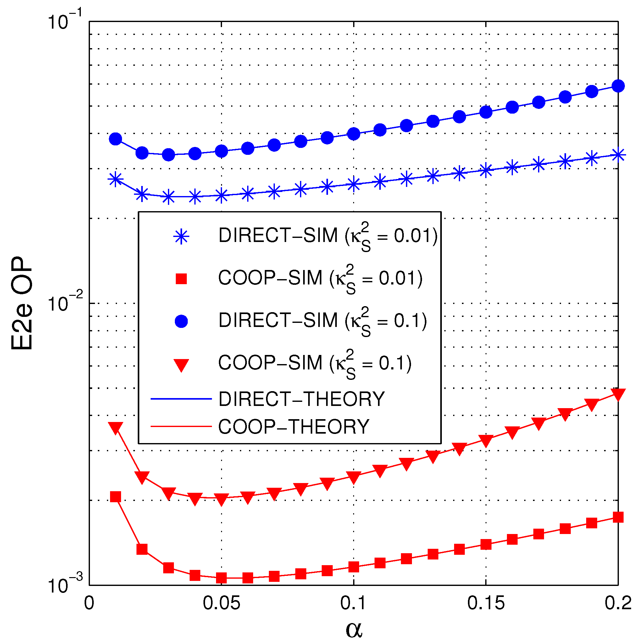
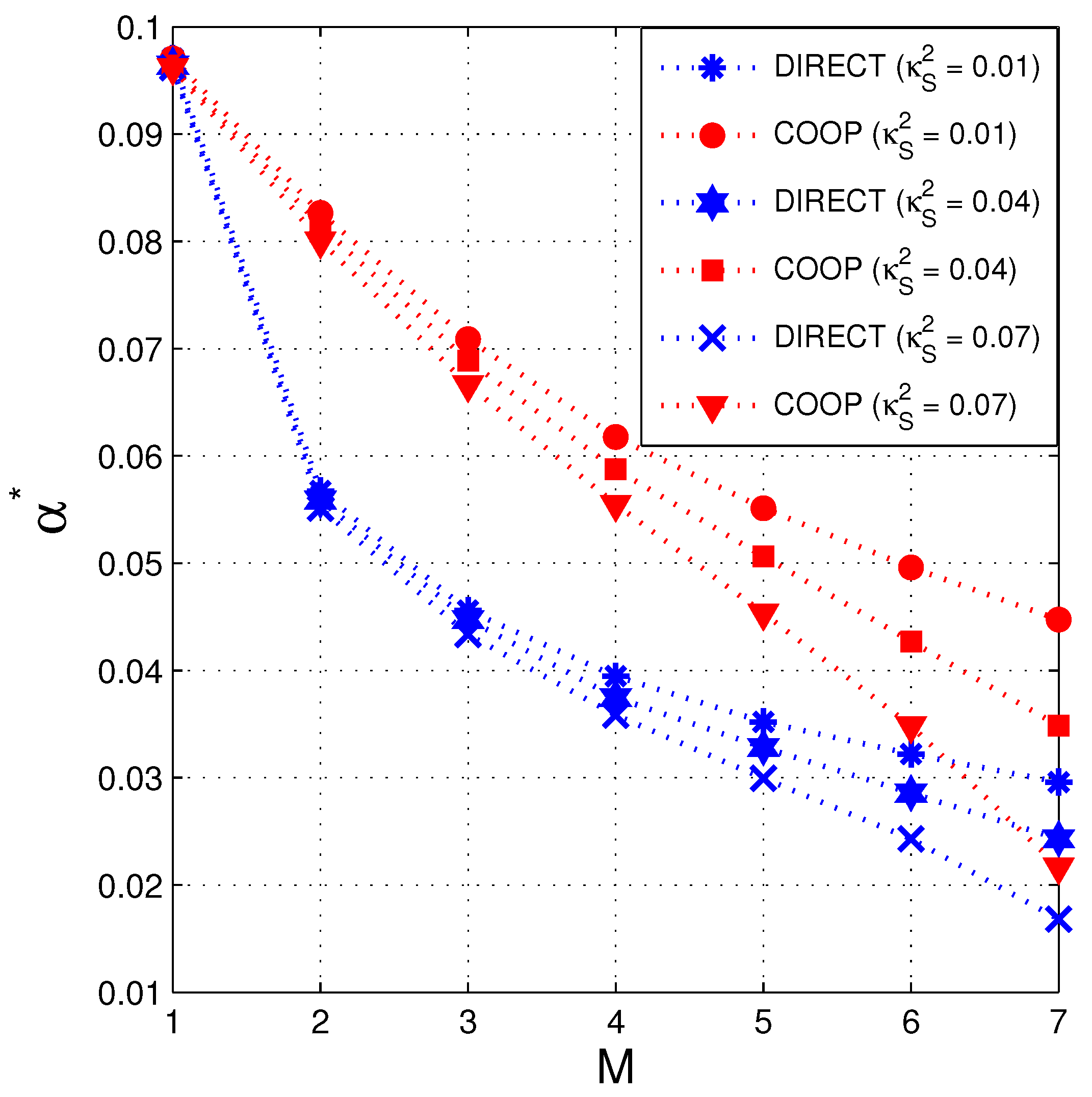
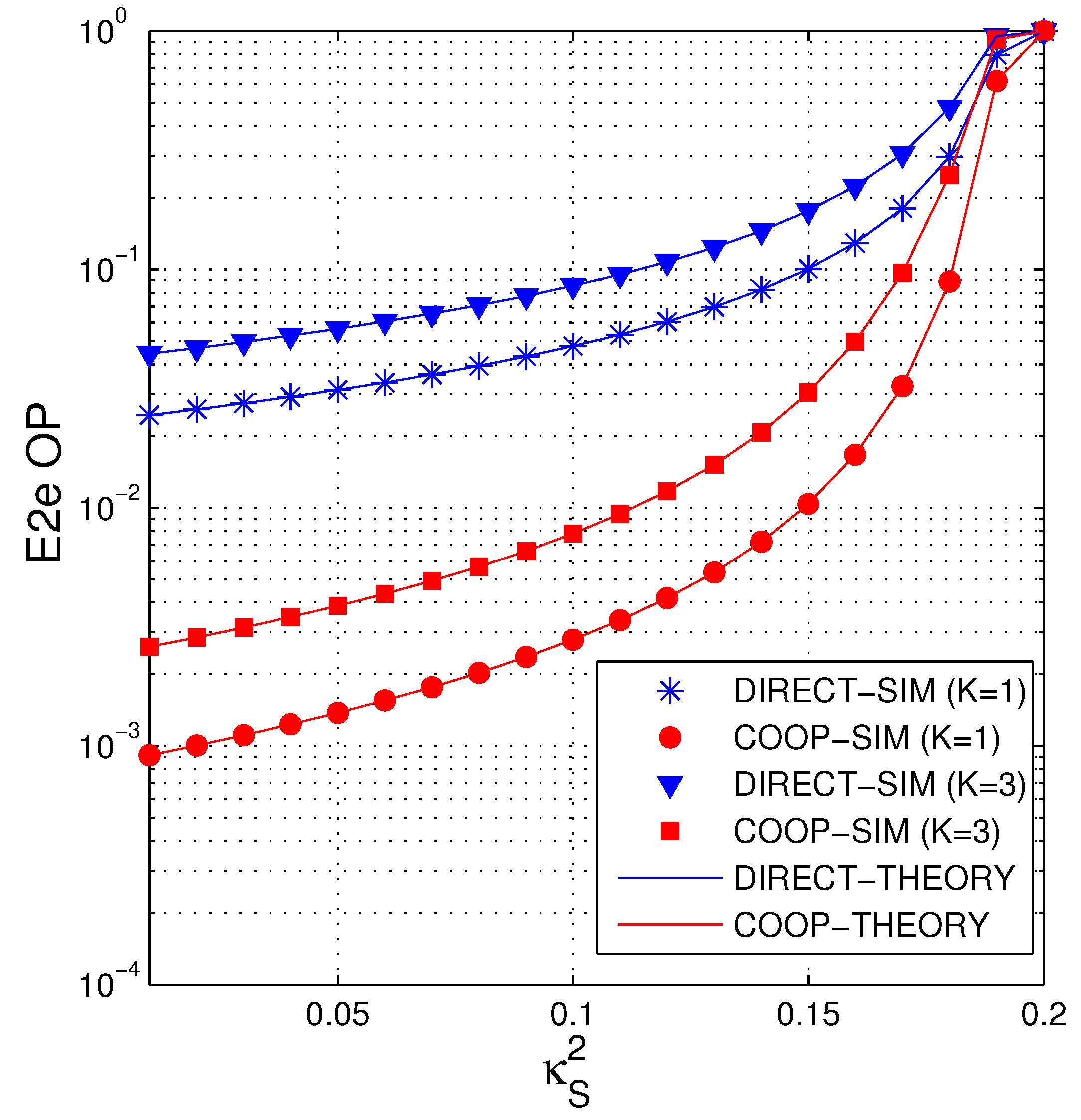
4. Simulation Results

Section 4 presents Monte-Carlo simulation results and the analytical results to verify the formulas attained in Section 3 as well as to compare the OP performance between DIRECT and COOP. In simulation environment, the node T m has co-ordinate of m / M , 0 , where m = 0 , 1 , , M , this means d T 0 , T M = 1 , d T m , T m + 1 = 1 / M . To mainly focus on the impact of the number of hops (M), the hardware impairment level of the data links ( κ S 2 ), the number of the power beacons (N), the number of the primary users (K), and the fraction of time ( α ) on O P COOP and O P DIRECT , the other system parameters are fixed in all the simulations as follows: the position of the power beacons are fixed at (0.5, 0.2); the primary users are located at (0.5, −0.5); the path-loss exponent β is set to 3, the value of the conversion efficiency μ is assigned by 0.5; the target rate C th is fixed by 0.5; the maximum e2e delay ( L ) is set to 1; the variance of Gaussian noises σ 0 2 equals to 1; and the HI level of the interference links ( κ P 2 ) is fixed by 0.01. Moreover, we set the interference threshold I th as I th = 0.5 Q B .
Figure 4 presents the e2e OP of COOP and DIRECT as a function of the transmit SNR ( Δ ) in dB with different values of N and K. As we can see, the performance of COOP and DIRECT is better when Δ increases. In addition, for given N and K values, OP of COOP is much lower than that of DIRECT, especially at high Δ regimes. We also observe that slope of O P COOP is higher than that of O P DIRECT because COOP obtains higher diversity gain (higher slope). Next, we also see that the performance of COOP and DIRECT increases with higher N and lower K. Indeed, in this figure, the best performance of COOP and DIRECT is obtained as N = 4 and K = 1 . It is due to the fact that the average transmit power of the secondary transmitters is higher when N increases, and K decreases. Finally, it is worth noting that the simulation and theoretical results are in an excellent agreement, which confirms correction of the derivations performed in Section 3.
Figure 5 presents O P COOP and O P DIRECT as functions of Δ in dB with different number of hops. As shown in Figure 5, the number of hops significantly impacts on the e2e OP values. We can see that COOP and DIRECT obtain the best performance as M = 4 . In DIRECT, the performance severely decreases with M = 7 , and the performance gap between M = 2 and M = 4 is slight. In COOP, the OP performance with M = 7 is better that with M = 2 at high Δ regions. Similar to Figure 4, it is also observed that COOP outperforms DIRECT, and the simulation results validate the theoretical ones.
In Figure 6, we present the e2e OP of COOP and DIRECT as a function of M with different values of the fraction α . When M = 1 , the source directly transmits its data to the destination, and hence the performance of COOP and DIRECT is same. We also see that when the number of hops (M) is high enough, COOP and DIRECT are always in outage, that is, O P COOP = O P DIRECT = 1 . It is due to the fact that the value of M max in this simulation is calculated as (see Remark 2)
M max = 9 , α = 0.05 8 , α = 0.1 & α = 0.2
Also observed from Figure 6, there exist optimal values of M so that the performance of COOP and DIRECT is best. For example, when α = 0.05 , the optimal values of M (denoted by M * ) in COOP and DIRECT are 3 and 4, respectively.
In Figure 7, we present the performance of COOP and DIRECT follows the transmit SNR Δ in dB when M = 2, M = 8 and M = M * . It is noted that the value of M * of COOP and DIRECT can be obtained via the following algorithm:
M * = argmin M = 1 , 2 , , M max O P V ,
where V COOP , DIRECT . Indeed, using the OP expressions obtained in (38) and (39), we easily find M * . In Table 1, we present M * follows Δ in dB. For example, when Δ = 12.5 dB, COOP and DIRECT obtain the optimal OP performance as M = 5 and M = 3 , respectively. As we can see from Figure 7, the e2e OP of COOP and DIRECT significantly decreases when M = M * .
Figure 8 illustrates the e2e OP of the considered protocols as a function of α , where 0.01 α 0.2 . We first see that O P COOP and O P DIRECT are high as α = 0.01 and α = 0.2 . It is due to the fact that when α is small (time allocated for the EH phases is small), the transmit power of the secondary transmitters is low, which leads to high OP values. However, when α is too high (time used for the data transmission is small), the instantaneous channel capacity of the data links decreases, and hence the OP performance is also worse. Next, it is shown in Figure 8 that there exist optimal values of α (denoted by α * ) so that the values of O P COOP and O P DIRECT is lowest. Next, we see that the HI level κ S 2 significantly effects on the e2e OP, that is, O P COOP and O P DIRECT decrease with lower value of κ S 2 .
Figure 9 illustrates the value of α * as a function of M. In this figure, one-dimensional Golden Section Search algorithm [50] is used to obtain α * . In particular, we have to determine an interval α low , α up that includes α * . Moreover, α low and α up have to satisfy the condition: α up α low 0.001 . Then, the output value of α * in this algorithm is determined by α * = α up + α low / 2 . Figure 9 shows that α * decreases with the increasing of M, and α * of COOP is higher than that of DIRECT. This means that the secondary transmitters in COOP needs more time for collecting the wireless energy than those in DIRECT. We also see from Figure 9 that α * of COOP and DIRECT is lower as κ S 2 increases.
In Figure 10, the impact of HIs on the e2e OP performance of COOP and DIRECT is investigated. As expected, the values of the e2e OP increases as κ S 2 increases. As mentioned in Remarked 2, COOP and DIRECT are always in outage once κ S 2 κ S , max 2 = 1 / ρ th . Hence, with κ S , max 2 = 0.1924 in this figure, this is the reason why O P COOP = O P DIRECT = 1 as κ S , max 2 = 0.2 . It is also depicted that the OP performance of COOP and DIRECT is better with lower value of K.

5. Conclusions

The obtained results in this paper showed that under the joint impact of the fading environment, the hardware imperfection and the interference constraint, the performance of the conventional multi-hop relaying protocol (i.e., DIRECT) was severely degraded. Hence, we proposed the multi-hop cooperative transmission protocol which exploited the spatial diversity to improve the outage performance. We also derived the exact expressions of the e2e OP for both DIRECT and COOP, and confirmed the correction via Monte Carlo simulations. Because the derived expressions are in closed form, they can be easily used by designers for optimizing the system performance. Indeed, we used the obtained formulas to find the optimal number of hops and the optimal fraction of the EH time for the considered protocols. The results presented that to obtain the best performance, COOP needs more number of hops and more EH time than DIRECT. For further improving the OP performance of the secondary network, the number of the power beacons and primary users should be carefully designed, and the secondary terminals should be equipped with better transceiver hardware.

Author Contributions

The main contributions of P.M.N., N.H.A. were to create the main ideas and execute performance evaluation by extensive simulations, while T.T.D., P.V.C. and P.N.S. worked as the advisers of P.M.N., N.H.A. to discuss, create, and advise the main ideas and performance evaluations together. All authors have read and agree to the published version of the manuscript.

Funding

This research is funded by Vietnam National Foundation for Science and Technology Development (NAFOSTED) under grant number 102.04-2017.317.

Conflicts of Interest

The authors declare no conflict of interest.

References

  1. Bansal, R. The Future of Wireless Charging [AP-S Turnstile]. IEEE Antennas Propag. Mag. 2009, 51, 153-153. [Google Scholar] [CrossRef]
  2. Sudevalayam, S.; Kulkarni, P. Energy Harvesting Sensor Nodes: Survey and Implications. IEEE Commun. Surv. Tutor. 2011, 13, 443–461. [Google Scholar] [CrossRef] [Green Version]
  3. Mishra, D.; De, S.; Jana, S.; Basagni, S.; Chowdhury, K.; Heinzelman, W. Smart RF Energy Harvesting Communications: Challenges and Opportunities. IEEE Commun. Mag. 2015, 53, 70–78. [Google Scholar] [CrossRef] [Green Version]
  4. Soyata, T.; Copeland, L.; Heinzelman, W. RF Energy Harvesting for Embedded Systems: A Survey of Tradeoffs and Methodology. IEEE Circuits Syst. Mag. 2016, 16, 22–57. [Google Scholar] [CrossRef]
  5. Huang, J.; Zhou, Y.; Ning, Z.; Gharavi, H. Wireless Power Transfer and Energy Harvesting: Current Status and Future Prospects. IEEE Wirel. Commun. 2019, 26, 163–169. [Google Scholar] [CrossRef] [PubMed]
  6. Nasir, A.A.; Zhou, X.; Durrani, S.; Kennedy, R.A. Relaying Protocols for Wireless Energy Harvesting and Information Processing. IEEE Trans. Wirel. Commun. 2013, 12, 3622–3636. [Google Scholar] [CrossRef] [Green Version]
  7. Di, X.; Xiong, K.; Fan, P.; Yang, H.C. Simultaneous Wireless Information and Power Transfer in Cooperative Relay Networks with Rateless Codes. IEEE Trans. Veh. Technol. 2017, 66, 2981–2996. [Google Scholar] [CrossRef]
  8. Nguyen, T.N.; Minh, T.H.Q.; Tran, P.T.; Voznak, M.; Duy, T.T.; Nguyen, T.L.; Tin, P.T. Performance Enhancement for Energy Harvesting Based Two-Way Relay Protocols in Wireless Ad-hoc Networks with Partial and Full Relay Selection Methods. Ad-Hoc Netw. 2019, 84, 178–187. [Google Scholar] [CrossRef]
  9. Tran, H.Q.; Nguyen, T.T.; Phan, C.V.; Vien, Q.T. Power-Splitting Relaying Protocol for Wireless Energy Harvesting and Information Processing in NOMA Systems. IET Commun. 2019, 13, 2132–2140. [Google Scholar] [CrossRef] [Green Version]
  10. In, C.; Kim, H.M.; Choi, W. Achievable Rate-Energy Region in Two-Way Decode-and-Forward Energy Harvesting Relay Systems. IEEE Trans. Commun. 2019, 67, 3923–3935. [Google Scholar] [CrossRef]
  11. Ju, M.; Kang, K.M.; Hwang, K.S.; Jeong, C. Maximum Transmission Rate of PSR/TSR Protocols in Wireless Energy Harvesting DF-based Relay Networks. IEEE J. Sel. Areas Commun. 2015, 33, 2701–2717. [Google Scholar] [CrossRef]
  12. Chen, Y. Energy-Harvesting AF Relaying in the Presence of Interference and Nakagami-m Fading. IEEE Trans. Wirel. Commun. 2016, 15, 1008–1017. [Google Scholar] [CrossRef] [Green Version]
  13. Hadzi-Velkov, Z.; Nikoloska, I.; Karagiannidis, G.K.; Duong, T.Q. Wireless Networks with Energy Harvesting and Power Transfer: Joint Power and Time Allocation. IEEE Signal Process. Lett. 2016, 23, 50–54. [Google Scholar] [CrossRef] [Green Version]
  14. Son, P.N.; Duy, T.T. Performance Analysis of Underlay Cooperative Cognitive Full-duplex Networks with Energy-Harvesting Relay. Comput. Commun. 2018, 122, 9–19. [Google Scholar]
  15. Ding, J.; Jiang, L.; He, C.; Shen, Y. Time Splitting Concurrent Transmission Framework and Resource Allocation in Wireless Powered Communication Networks. IEEE Trans. Green Commun. Netw. 2018, 2, 666–678. [Google Scholar] [CrossRef]
  16. Atapattu, S.; Evans, J. Optimal Energy Harvesting Protocols for Wireless Relay Networks. IEEE Trans. Wirel. Commun. 2016, 15, 5789–5803. [Google Scholar] [CrossRef]
  17. Xu, K.; Shen, Z.; Wang, Y.; Xia, X.; Zhang, D. Hybrid Time-Switching and Power Splitting SWIPT for Full-Duplex Massive MIMO Systems: A Beam-Domain Approach. IEEE Trans. Veh. Technol. 2018, 67, 7257–7274. [Google Scholar] [CrossRef]
  18. Jiang, R.; Xiong, K.; Fan, P.; Zhang, Y.; Zhong, Z. Power Minimization in SWIPT Networks With Coexisting Power-Splitting and Time-Switching Users Under Nonlinear EH Model. IEEE Internet Things J. 2019, 6, 8853–8869. [Google Scholar] [CrossRef]
  19. Zheng, G.; Krikidis, I.; Masouros, C.; Timotheou, S.; Toumpakaris, D.A.; Ding, Z. Rethinking the Role of Interference in Wireless Networks. IEEE Commun. Mag. 2014, 52, 152–158. [Google Scholar] [CrossRef]
  20. Zhao, N.; Zhang, S.; Yu, F.R.; Chen, Y.; Nallanathan, A.; Leung, V.C. Exploiting Interference for Energy Harvesting: A Survey, Research Issues, and Challenges. IEEE Access 2017, 5, 10403–10421. [Google Scholar] [CrossRef]
  21. Ma, Y.; Chen, H.; Lin, Z.; Li, Y.; Vucetic, B. Distributed and Optimal Resource Allocation for Power Beacon-Assisted Wireless-Powered Communications. IEEE Trans. Commun. 2015, 63, 3569–3583. [Google Scholar] [CrossRef] [Green Version]
  22. Zhou, X.; Guo, J.; Durrani, S.; Di Renzo, M. Power Beacon-Assisted Millimeter Wave Ad Hoc Networks. IEEE Trans. Commun. 2018, 66, 830–844. [Google Scholar] [CrossRef]
  23. Le, N.P. Throughput Analysis of Power-Beacon-Assisted Energy Harvesting Wireless Systems over Non-Identical Nakagami-m Fading Channels. IEEE Commun. Lett. 2018, 22, 840–843. [Google Scholar] [CrossRef]
  24. Liang, K.; Zhao, L.; Zheng, G.; Chen, H.H. Non-Uniform Deployment of Power Beacons in Wireless Powered Communication Networks. IEEE Trans. Wirel. Commun. 2019, 18, 1887–1899. [Google Scholar] [CrossRef] [Green Version]
  25. Zhang, C.; Zhao, G. On the Deployment of Distributed Antennas of Power Beacon in Wireless Power Transfer. IEEE Access 2018, 6, 7489–7502. [Google Scholar] [CrossRef]
  26. Mao, M.; Cao, N.; Chen, Y.; Zhou, Y. Multi-Hop Relaying Using Energy Harvesting. IEEE Wirel. Commun. Lett. 2015, 4, 565–568. [Google Scholar] [CrossRef] [Green Version]
  27. Chen, E.; Xia, M.; da Costa, D.B.; Aissa, S. Multi-Hop Cooperative Relaying with Energy Harvesting from Co-channel Interferences. IEEE Commun. Lett. 2017, 21, 1199–1202. [Google Scholar] [CrossRef]
  28. Lakshmi, S.P.; Jibukumar, M.G. SWIPT in Multi-Hop Amplify-and-Forward Wireless Sensor Networks. Int. J. Electron. 2019, 107, 630–643. [Google Scholar]
  29. Fan, R.; Atapattu, S.; Chen, W.; Zhang, Y.; Evans, J. Throughput Maximization for Multi-Hop Decode-and-Forward Relay Network with Wireless Energy Harvesting. IEEE Access 2018, 6, 24582–24595. [Google Scholar] [CrossRef]
  30. So-In, C.; Tran, D.D.; Tran, H. Optimal System Performance in Multihop Energy Harvesting WSNs Using Cooperative NOMA and Friendly Jammers. IEEE Access 2019, 7, 125494–125510. [Google Scholar]
  31. Mitola, J.; Maguire, G.Q. Cognitive Radio: Making Software Radios More Personal. IEEE Pers. Commun. 1999, 6, 13–18. [Google Scholar] [CrossRef] [Green Version]
  32. Peha, J.M. Approaches to Spectrum Sharing. IEEE Commun. Mag. 2005, 43, 10–12. [Google Scholar] [CrossRef]
  33. Zeng, Z.; Liu, M.; Wang, J.; Lan, D. Non-Cooperative Spectrum Access Strategy Based on Impatient Behavior of Secondary Users in Cognitive Radio Networks. Electronics 2019, 8, 995. [Google Scholar] [CrossRef] [Green Version]
  34. Alvi, S.A.; Hussain, R.; Hasan, Q.U.; Malik, S.A. Improved Buffer-Aided Multi-Hop Relaying with Reduced Outage and Packet Delay in Cognitive Radio Networks. Electronics 2019, 8, 895. [Google Scholar] [CrossRef] [Green Version]
  35. Hong, J.P.; Hong, B.; Ban, T.W.; Choi, W. On the Cooperative Diversity Gain in Underlay Cognitive Radio Systems. IEEE Trans. Commun. 2012, 60, 209–219. [Google Scholar] [CrossRef]
  36. He, P.; He, G.M.; Zhao, L. Optimal Power Allocation for MIMO-MAC in Cognitive Radio Networks. Electronics 2014, 3, 538–552. [Google Scholar] [CrossRef] [Green Version]
  37. Zheng, K.; Liu, X.Y.; Liu, X.; Zhu, Y. Hybrid Overlay-Underlay Cognitive Radio Networks with Energy Harvesting. IEEE Trans. Commun. 2019, 67, 4669–4682. [Google Scholar] [CrossRef]
  38. Xu, C.; Zheng, M.; Liang, W.; Yu, H.; Liang, Y.C. Outage Performance of Underlay Multihop Cognitive Relay Networks with Energy Harvesting. IEEE Commun. Lett. 2016, 20, 1148–1151. [Google Scholar] [CrossRef]
  39. Xu, C.; Zheng, M.; Liang, W.; Yu, H.; Liang, Y.C. End-to-End Throughput Maximization for Underlay Multi-hop Cognitive Radio Networks with RF Energy Harvesting. IEEE Trans. Wirel. Commun. 2017, 16, 3561–3572. [Google Scholar] [CrossRef]
  40. Boddapati, H.K.; Bhatnagar, M.R.; Prakriya, S. Performance Analysis of Cluster-Based Multi-hop Underlay CRNs Using Max-Link-Selection Protocol. IEEE Trans. Cogn. Commun. Netw. 2018, 4, 15–29. [Google Scholar] [CrossRef]
  41. Boddapati, H.K.; Bhatnagar, M.R.; Prakriya, S. Performance of Incremental Relaying Protocols for Cooperative Multihop CRNs. IEEE Trans. Veh. Technol. 2018, 67, 6006–6022. [Google Scholar] [CrossRef]
  42. Hieu, T.D.; Duy, T.T.; Choi, S.G. Performance Evaluation Of Relay Selection Schemes in Beacon-Assisted Dual-Hop Cognitive Radio Wireless Sensor Networks Under Impact of Hardware Noises. Sensors 2018, 18, 1843. [Google Scholar] [CrossRef] [PubMed] [Green Version]
  43. Karaca, H.M. Throughput Optimization of Multichannel Allocation Mechanism Under Interference Constraint for Hybrid Overlay/Underlay Cognitive Radio Networks with Energy Harvesting. Electronics 2020, 9, 330. [Google Scholar] [CrossRef] [Green Version]
  44. Laneman, J.N.; Tse, D.N.; Wornell, G.W. Cooperative Diversity in Wireless Networks: Efficient Protocols and Outage Behavior. IEEE Trans. Inf. Theory 2004, 50, 3062–3080. [Google Scholar] [CrossRef]
  45. Quang, P.M.; Duy, T.T.; Bao, V.N.Q. Performance Evaluation of Radio Frequency Energy Harvesting-Aided Multi-hop Cooperative Transmission Networks. In Proceedings of the 2019 25th Asia-Pacific Conference on Communications (APCC), Ho Chi Minh City, Vietnam, 6–8 November 2019; pp. 521–526. [Google Scholar]
  46. Papoulis, A.; Pillai, S.U. Probability, Random Variables, and Stochastic Processes; Tata McGraw-Hill Education: New York, NY, USA, 2002. [Google Scholar]
  47. Bjornson, E.; Hoydis, J.; Kountouris, M.; Debbah, M. Massive MIMO Systems With Non-Ideal Hardware: Energy Efficiency, Estimation, and Capacity Limits. IEEE Trans. Inf. Theory 2014, 60, 7112–7139. [Google Scholar] [CrossRef] [Green Version]
  48. Amari, S.V.; Misra, R.B. Closed-form Expressions for Distribution of Sum of Exponential Random Variables. IEEE Trans. Reliab. 1997, 46, 519–522. [Google Scholar] [CrossRef]
  49. Gradshteyn, I.S.; Ryzhik, I.M. Table of Integrals, Series, and Products; Academic Press: London, UK, 2014. [Google Scholar]
  50. Chong, E.K.; Zak, S.H. An Introduction to Optimization; John Wiley & Sons: New York, NY, USA, 2004. [Google Scholar]
Figure 1. System model of power beacon (PB)-aided multi-hop cooperative cognitive radio protocol.
Electronics 09 01054 g001
Figure 2. Point-to-point communication scheme in the radio frequency energy harvesting (RF-EH) and underlay spectrum sharing (USS) environment.
Electronics 09 01054 g002
Figure 3. Point-to-multi-point communication scheme in the RF-EH and USS environment.
Electronics 09 01054 g003
Figure 4. E2e OP as a function of Δ (dB) when M = 4 , κ S 2 = 0.1 , α = 0.1 .
Electronics 09 01054 g004
Figure 5. E2e OP as a function of Δ (dB) when N = 2 , K = 2 , κ S 2 = 0.05 , α = 0.05 .
Electronics 09 01054 g005
Figure 6. E2e OP as a function of M when Δ = 20 (dB), N = 3 , K = 1 , κ S 2 = 0.05 .
Electronics 09 01054 g006
Figure 7. E2e OP as a function of Δ (dB) when N = 1 , K = 1 , κ S 2 = 0.05 , α = 0.05 .
Electronics 09 01054 g007
Figure 8. E2e OP as a function of α when Δ = 20 (dB), M = 4 , N = 3 , K = 1 .
Electronics 09 01054 g008
Figure 9. Optimal value of α * as a function of M when Δ = 20 (dB), N = 2 , K = 2 .
Electronics 09 01054 g009
Figure 10. E2e OP as a function of κ S 2 when Δ = 20 (dB), M = 5 , N = 5 , α = 0.05 .
Electronics 09 01054 g010
Table 1. Optimal number of hops ( M * ) as a function of Δ.
Δ(dB) 02.557.51012.51517.52022.525
M * (DIRECT)33333334444
M * (COOP)34444555555

