1. Introduction
In recent years, blockchain, the underlying technology behind the famous Bitcoin [
1], gain tractions because of its ability to facilitate a working decentralized payment system without the need of a central third party. This phenomenon creates a momentum to apply blockchain technology to other sectors; one of them is the Internet of Things (IoT) [
2]. Recent surveys in the United States also tells that 75% of IoT firms have already implemented or plan to apply blockchain in the next year [
3]. They say that by integrating blockchain into their IoT systems, they can get benefits such as increased security and trust in multi-party business scenarios. The introduction of the smart contract [
4], a Turing-complete program that runs on the blockchain, is a game-changer for blockchain in IoT. The smart contract allows us to automate tedious IoT workflows, increase business efficiency, and lowers the cost, while still under the umbrella of the security and trust guarantee of the blockchain.
However, despite promising features that blockchain can offer to IoT, we argue that the current blockchain infrastructure is not suitable for the IoT environment. For starters, the massive requirements, in terms of computing, storage, and networking, to run the blockchain node contradicts the nature of IoT devices, which mostly are constrained devices. Second, the design of the blockchain does not allow us to process transactions in parallel. This restriction exists because the blockchain needs to provide a security guarantee required to detect double spending attempts. Third, the performance of a blockchain network depends on the consensus algorithm that lays under the hood. Explicitly, no consensus algorithm can guarantee high transactions throughput while maintaining a high number of nodes at the same time. Thus, adopters sometimes have to choose between one of those two extremes [
5].
Driven by these issues, we propose a scheme to scale the blockchain for IoT by combining multiple blockchain networks hierarchically. More specifically, we divide the role of blockchain networks into four parts—the Payment Engine, the Compute Engine, the Storage Engine, and the Core Engine. The given name implies the role of each engine. The Payment Engine is responsible for all of the IoT micropayments in the system. The Compute Engine governs the smart contract computations and performs IoT processing logic. The Storage Engine manages the IoT data storage. Lastly, the Core Engine becomes a parent of all of the other engines, which has a role in controlling the collaborations between those engines.
Generally, the nature of hierarchical design brings centralization to the architecture. The top tier node most likely will become the supernodes and the ruler of all nodes. However, in our architecture, we mitigate this centralization issue by delegating a board of nodes to govern this tier. Thus, we employ a mix of centralized and decentralized architecture. Furthermore, we use a hybrid consensus in our architecture by implementing multiple consensus protocols, the Byzantine Fault Tolerant (BFT) variant consensus in the Core Engine, and other consensus in each of the underlying engines. The sub-engine protocol may vary depending on the implementation of the respective engine. This decision allows the Core Engine to be resilient during high load, and eventually scale the whole architecture. Moreover, to enhance the scalability even further, we also enable parallelism on subordinate engines (sub-engines) such that we can delegate tasks to multiple instances of sub-engines at the same time.
To sum up, we make the following contributions.
We propose a two-layer hierarchical multi-blockchain architecture to scale the blockchain implementations for IoT environments. We categorize the low-tiered blockchain networks by their respective IoT workflows, which are the Payment, the Compute, and the Storage Engine. Then, the high-tiered network exists to manage the underlying networks by providing features such as sub-engine parallelism and interoperability between sub-engine.
We expose all of our proposed engines in the form of Application Programming Interfaces (APIs). Developers can use these APIs to develop IoT applications (apps) on top of our architecture. In this paper, we have created an IoT car rental demo application as a proof-of-concept implementation.
We find that the signing and verification of transactions cause a lot of burden in our Core Engine. Therefore, we propose to aggregate Core Engine requests by using a request pool mechanism. Furthermore, we also propose a priority scheme through a Proxy node that will prioritize the flow of important IoT app data over the insignificant one so that the system can process them quickly.
We evaluate our architecture by conducting some experiments to measure the performance of the Core Engine, as well as measuring the latency across the sub-engines. These experiments showcase the effectiveness of our request pool mechanism in increasing the throughput of the Core Engine. They also show that our priority algorithm can work correctly and can adapt to the dynamic workload of the IoT data traffic accordingly. Finally, the results from our local experiments show that the proposed architecture can process the cross engine communication with reasonable latency.
We organize the rest of the paper as follows.
Section 2 discusses backgrounds and our motivations for this paper.
Section 3 elaborates the general view of our proposed hierarchical multi-blockchains architecture.
Section 4 explains our blockchain of choices to serve as Payment, Compute, and Storage Engine.
Section 5 details the Core Engine, as well as our proposal for request aggregation, request prioritization, and sub-engine parallelism. After that, in
Section 6, we showcase our IoT car rental application demo that leverages the APIs in our architecture. We then describes our implementations in
Section 7 and evaluate in
Section 8.
Section 9 discuss the related works and our suggestions on deploying our architecture in the production scenario. Finally, we conclude and provide our future work in
Section 10.
2. Blockchain Scalability Issues for IoT
In this section, we survey several studies from the literature and present our argument on the scalability issues that the blockchain possesses, such that it becomes unsuitable for the IoT environment. This section also reflects our motivation in general in proposing a new blockchain architecture for the IoT.
2.1. Most of the IoT Devices Are Not Suitable to Run a Blockchain Node
The state-of-the-art blockchain cannot scale well for IoT because of the tremendous requirements that a blockchain node has to bear in order to join the blockchain network. Meanwhile, the nature of the IoT devices is mostly resource-constrained devices. Therefore, most of them cannot become a blockchain node and get benefits of the blockchain.
First of all, the node has to do “work” that involves CPU-utilization. Depending on the consensus algorithm, some blockchain networks such as Bitcoin [
1] and Ethereum [
6] mandates the node to solve a cryptographic puzzle to achieve consensus. This process is notably known as Proof-of-Work (PoW) or mining. It is a CPU-intensive course of actions such that the majority of IoT devices cannot perform well enough. For example, a Raspberry Pi 2 takes 3082 seconds to solve a PoW puzzle and wastes 5.3 KJ of energy in doing so [
7]. This metric should worsen on more constrained IoT devices such as Arduino Uno or wireless sensor devices, assuming that the device can even run PoW onboard.
Second, the node needs to spare some physical drive spaces to save the distributed ledger data on their local storage. The number of bytes that they have to reserve depends on the overall usage on the blockchain network. The more transactions that the users send, the more data that the node has to save. Hence, the data size can scale exponentially to the age of the blockchain. Specifically, the longer the blockchain lives, the more transactions will arise, result in a more significant ledger size requirement. For instance, at the time of the writing of this paper, we need at least 200 GB of free storage and 2 GB RAM to run a full node of Bitcoin [
8], in about ten years of operations. Ethereum supports the smart contract, allowing the node to store arbitrary data in the blockchain aside from the cryptocurrency data. In consequence, the blockchain size of Ethereum has exceeded 1 TB [
9], in just about three years of operation. IoT devices have limited storage, a gigabyte and terabyte-level of storage are absurd for IoT devices.
Third, a blockchain node is necessary to have a constant network communication to the other peers. Otherwise, he cannot get up-to-date ledger information from the network. This requirement means that the node has to stay alive most of the time. However, some IoT devices, especially those in the wireless sensor network domain, require to preserve their batteries. Therefore, in contrast, they should be in a sleep mode in the majority of their time. Moreover, due to the big size of the blockchain ledger, it requires a high amount of network bandwidth to synchronize the blockchain node with other peers in the network to get the latest network state during the startup. When multiple nodes are starting up simultaneously, synchronization packets can fill up the network.
Finally, since there is no one governing the blockchain network, the system has to come up with an incentive mechanism to maintain the majority of the nodes to behave honestly. One possible source of this incentive comes from the donation of the nodes in terms of transaction fees. Specifically, when one wants to send a payment or store data via transactions on the blockchain, he has to pay a transaction fee. Once the system includes his transaction in the blockchain, the system will give the cumulative fee to the miner. We are expecting to see many flows of transactions happen in the IoT network. Thus, we have to consider the economics of the micro-transaction fee. We argue that it is not viable for IoT devices to pay much money for the sake of doing IoT related workflows.
2.2. Blockchain Design Cannot Process Transaction in Parallel
In general, the blockchain has to process the transaction data sequentially, one block at the time. By doing so, the system can verify all of the transactions included in the block securely and safely. Particularly, the blockchain should always guarantee to not include a double spent transaction. Otherwise, others will distrust the blockchain, and result in unusability. Due to this security protection, the block processing time is slow. When many transactions come in, the number of pending or orphaned transactions may increase as the result of the slow processing rate.
Two types of data structure models are popular among blockchains nowadays, the Account and the Unspent Transaction Output (UTXO) model. In the account model (e.g., Ethereum [
6]), the number of coins or money that each user has is stored as an account balance. The system then synchronizes the current balance with other peers to form a global account balance state. This model resembles how we store our money in banks, or how we save our data in a replicated database. It also allows us to build a smart contract, a distributed program across nodes. However, because the global state requires consistency, it is difficult to perform parallelism in this model.
Instead of keeping the state of the current balance, in the UTXO model (e.g., Bitcoin [
1]), the wallet keeps a list of transactions that still has unspent outputs under his keys. This design decision results in managing the balance become more complex since we have to traverse previous transactions to validate a coming transaction. However, this design is more scalable as we can potentially process multiple unrelated and independent transactions concurrently.
An alternative way to achieve parallelism is by proposing a different distributed ledger design via the Directed Acyclic Graph (DAG), a graph with directed edges and no cycles. The authors of Reference [
10] tweak the blockchain structure to work with the DAG; they call it BlockDAG, a hybrid between the block and DAG data structure. Instead of one block refers to one parent block, thus forming a linear chain of blocks, the system allows blocks that have no conflicting transactions to form a DAG to the other blocks. In this graph, the node represents the block, and the edge represents the previous hash relationships between blocks.
Another proposal, called IOTA [
11], abandons the blockchain data structure entirely. Similarly to the blockchain UTXO model, a valid transaction in IOTA has to point or refer to the previous transactions as a way for other nodes to verify the source of the money in the transaction. However, IOTA does not group transactions into a block, which causes a bottleneck in the regular blockchain. Instead, the transactions form a DAG. In this graph, the node represents the transaction, and the edge represents the UTXO relationship between transactions. This way, separated IOTA transactions that do not depend on one another can form a graph simultaneously.
2.3. Blockchain Consensus Trade-Off
The performance of blockchains relies heavily on the underlying consensus protocol between peers. The goal for the scalability of a decentralized IoT platform is to have a distributed system that can process many IoT workloads (or transactions in terms of blockchain) for a huge number of IoT devices (or blockchain nodes). However, looking at the state-of-the-art solutions, we cannot achieve this objective at this moment, mainly because current blockchain consensus are separated into two extremes: the Proof-of-Work (PoW) variant and the Byzantine Fault Tolerance (BFT) variant [
5].
The PoW is a fully decentralized consensus protocol, firstly adopted in Bitcoin [
1]. The network constructed using this protocol is open for the public; anyone can join the network as the blockchain nodes. Therefore, it has the properties to scale to a high number of nodes. The weakness of this protocol is the throughput of the network, in terms of generated transaction per second (Tx/s), is small. For example, Bitcoin can only process 7 Tx/s while Ethereum achieves 15 Tx/s [
12]. This constraint exists because of the limited block size and difficulty setting to ensure the safety and fairness of the system. The system also has to make sure that the number of possible forks in the system remains low, and that the proposed blocks can propagate to all the nodes scattered in the entire world.
The wide gap between these PoW-variant throughput numbers to the VISA throughput, which can process up to 24,000 Tx/s [
12], opens the discussion for researchers to use the consensus from the traditional distributed system. Mainly, the BFT variant [
13]. This protocol is well known for its high throughput. However, studies show that the BFT-variant blockchain fails to scale to a hundred of nodes [
14]. Another study can even only run BFT up to 16 nodes [
15]. Thus, even though the throughput is high, the number of nodes that can join the network is limited. In consequence, this consensus protocol is more likely to be centralized.
Finally, based on these two consensus algorithms, we can categorize the blockchain into two types. This first variant is called permissionless blockchain, also known as the public blockchain, which allows anyone to become a blockchain node by contacting seed nodes directly, without the need for authentications. This blockchain usually applies the PoW-variant consensus. The second blockchain is more private compared to its sibling, called the permissioned blockchain. A new node has to get authorization from the network administrator before joining the network. This nature exists due to the requirements in the consensus protocol to know the identity of other nodes before the network started. While this authentication helps in creating stronger trust between nodes, it may hinder new users’ registration as potential contributors in our blockchain network.
3. Proposed Architecture
Based on our reflections and analysis from the scalability issues in the previous section. We design our architecture to have the following properties.
Hybrid architecture. We argue that not all aspects of the blockchain for the IoT need to be decentralized. A fully decentralized IoT architecture is not feasible in the current state. For instance, we still need a centralized gateway to cluster and manage IoT devices in the field efficiently. At some point, we also depend on the centralized Internet Service Provider (ISP) or the Cloud Service to deliver, store, and process our IoT data. Therefore, we propose to use the combination of quasi-centralized and fully-decentralized IoT architecture (in other words, a mixed of permissioned and permissionless network) to get a better scalability factor while minimalizing the impact of centralization as low as possible.
Hybrid consensus. Recall our previous discussion on the consensus trade-off; one has to choose either to have a high throughput or a high number of nodes. One idea to solve this problem is by borrowing the structure of the Internet. Specifically, we can have a blockchain network that serves as a backbone network to process as many transactions as possible, most probably using a BFT-variant consensus. This network will have a low number of nodes (not more than a hundred) but a high throughput. Under this backbone network, we can have several low throughput sub-networks (sub-blockchains) that can cope with many IoT devices.
Scaling via sub-blockchains. Inside those sub-blockchains, we can delegate IoT tasks from the backbone networks. By doing so, we can project several benefits. First, distributing transactions to the subordinate blockchains can relieve the burden of the core network, thereby increasing the overall scalability of the system. Furthermore, we can enable sub-blockchain parallelism, in which we can deploy multiple instances of the sub-blockchain working on many IoT tasks simultaneously. Finally, having multiple instances of sub-blockchains means that we can reduce the size of the stored data ledger in the subordinate nodes. Thus, we can bring down the minimum storage requirements to become a blockchain node in the sub-blockchain. As a result, we have a higher chance that a particular device can join the blockchain.
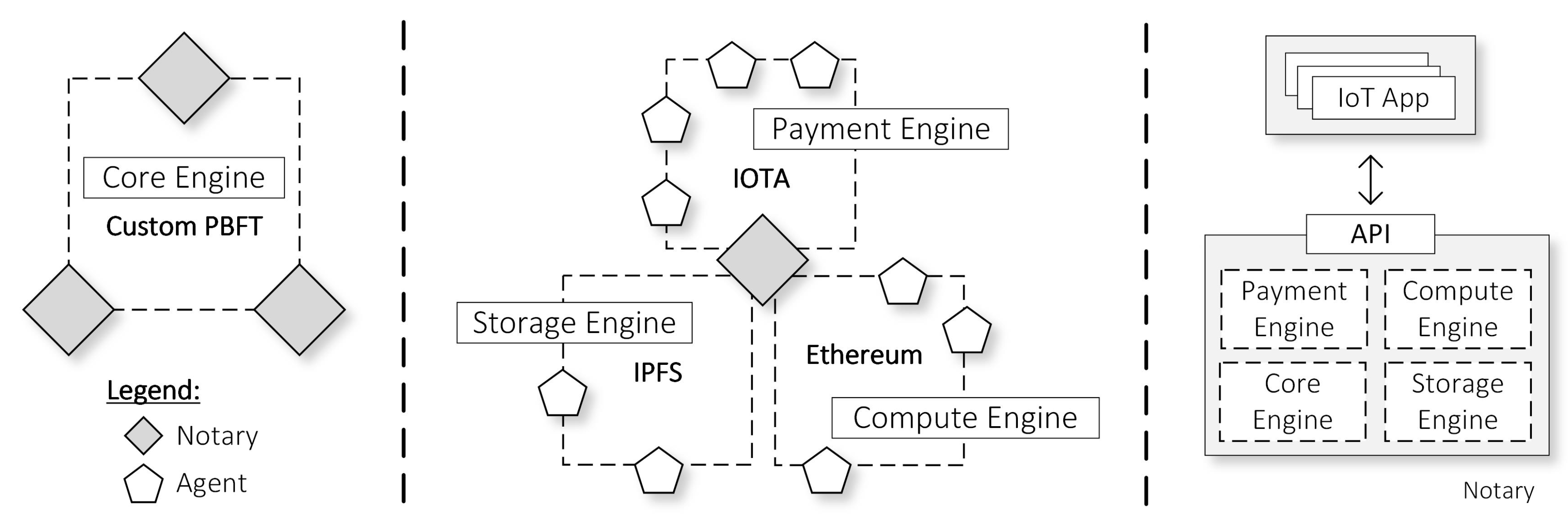
Our proposed architecture, depicted in
Figure 1, is a hierarchical IoT architecture comprising multiple blockchain networks, which we refer them as engines. First of all, the Core Engine is a central engine that acts as the core processor in our architecture. Then, we have three sub-engines as complementary engines that support the Core Engine, each of which has a specific role. First, the Payment Engine is responsible for all IoT-related economic transactions that happen in our architecture. Second, the Compute Engine provides smart contract execution services to process all of our IoT business logic. Third, the Storage Engine facilitates storage service to save the IoT raw or analytics data. We leverage the sub-chain concept to delegate payment transactions, computation tasks, and data storage to the sub-engines. Furthermore, by abusing delegation, we can perform parallelism in which we deploy multiple sub-engines in the system.
In the system, Notary nodes exist to manage all engines in a distributed and cooperative manner. For starters, all of the Notary nodes share the responsibility to govern the Core Engine. Furthermore, the Notary nodes are also in charge of sub-engines, which they handle collaboratively with subordinate nodes that we call Agent nodes. Depending on the types of sub-engine and use cases, these Agent nodes can be in the form of an IoT server, an IoT user, an IoT gateway, or an IoT device. Developers run their IoT applications distributedly on top of available Notary nodes. The Notary node opens all sub-engines features to IoT applications through the Application Programming Interfaces (APIs), which we call the Engine API. With this API, IoT apps can store IoT data, validate payments, and change the state of smart contracts.
The Notary indeed has a crucial role in managing our architecture, and others may concern about its centralization issue. By committing to our proposal, IoT participants must trust the Notary nodes. However, we argue that a single Notary node cannot take over control 100% of the system for several reasons. First, Agent nodes are involved in the execution of processes in each of the sub-engines. They can make sure that sub-engine procedures are performed correctly such that when the Notary node behaves maliciously, they can detect it. To compromise the system, attackers then must take control of a Notary node, as well as several Agent nodes in each of the sub-engines. Second, the node runs a BFT-variant consensus to synchronize the IoT app state with other instances of Notary node. Hence, attackers have to take over at least 33% of the Notary nodes to take over the Core Engine.
4. Sub Engines
We decided to separate the sub-engines to work on specific IoT workflows because there is no one-size-fits-all blockchain solution that can satisfy all of the requirements. For example, our Payment Engine, IOTA, can process money transactions fast and scale to many users because they use DAG and UTXO model that enables parallelism in its core design. However, this engine does not support smart contract executions. Meanwhile, our Compute Engine, Ethereum, has a reliable smart contract platform that enables us to create distributed applications. However, they are very slow to process and require a lot of gas or transactions fee to store data inside the smart contract. Therefore, we still need IPFS as a Storage Engine to store IoT raw data. By having all of the sub-engines to focus on the tasks that they are excel at, we can have a workaround solution in achieving the best world of blockchains. The following paragraphs detail our rationale in choosing those previously mentioned blockchains as our candidate for sub-engines.
4.1. Payment Engine
The Payment Engine is one of the sub-engines that responsible for all of the economic transactions in our IoT architecture. While theoretically, any blockchain that supports cryptocurrency can perform as the Payment Engine, the IoT payments are quite different from traditional e-commerce payments. Therefore we came up with several qualifications for the Payment Engine.
High throughput. The Payment Engine has to perform well under heavy loads of IoT transactions and support a high number of transactions per second. The state-of-the-art 7 and 15 transactions per second that are achievable through Bitcoin and Ethereum respectively, clearly do not satisfy this requirement.
Fast confirmation. Due to the possibility of orphaned blocks when there is a fork in the blockchain, merchants usually have to wait for several blocks before deciding to process the paid requests from buyers. This delay can hinder real-time IoT application use cases.
Low transaction fees. To compensate for the electricity that miners have to waste during mining operations, Bitcoin and Ethereum have transaction fees. Users that want a fast-confirmation transaction then may have to pay a high transaction fee. During peak times, the price for these fees can rise to the point that the fees are higher than the actual money that users want to transfer in the transactions. With most of the IoT payments are micropayments, a high transaction fee scheme is not suitable for IoT.
Based on those requirements, in this paper, we decided to use IOTA [
11] as our Payment Engine. First of all, IOTA theoretically can scale as the number of users using the network is increasing. This high number of active users result in transactions also become faster to be confirmed. To cope with micropayments, IOTA has no transaction fees. Furthermore, some IoT devices have to conserve battery or are required to be mobile. Thus, those devices may not be able to connect to the Internet at all times. With IOTA, we can create offline transactions temporarily and then publish it in the network when we gain Internet connectivity.
4.2. Compute Engine
The main task of the Compute Engine is to enforce IoT business logic and policy rules in a secure and distributed manner. We can leverage the characteristics of smart contracts in the blockchain to realize this. All of the functions in the smart contract are deterministic and transparent. Once we deploy a smart contract, the system will replicate it so that it is accessible locally on each node. Thus, all of the blockchain nodes have the same view of the smart contract code and the data stored in the smart contract. Multiple parties then can trust the execution of the smart contract such that the contract will most likely execute multi-party business logic honestly.
The additional role of the smart contract is to store IoT metadata in the blockchain. We understand that storing data in the blockchain is tamper-proof and safe. However, storing IoT data in the blockchain is expensive in terms of cost and storage. Thus, we have to limit the data stored in the blockchain by only saving essential data such as IoT metadata. We can keep the rest of the data in the Storage Engine, which we explain in the next subsection.
We also have to mention that not all blockchains have the same Turing-complete smart contract. For instance, the embedded script capability in the Bitcoin is not Turing-complete [
16]. The script cannot process complex operations such as loopings. It also does not have a way to maintain the state of the program. Thus, multi-stage operations are not practical. On the other hand, Hyperledger and Ethereum have more advance smart contracts, but the one provided in the Hyperledger is inefficient since it relies heavily on the key-value store. To provide the same contract logic, Ethereum ends up having way lesser number of line codes than the Hyperledger [
15]. Therefore, we decided to use the Ethereum [
6] as our Compute Engine because the smart contract in Ethereum is more expressive compared with those previously mentioned blockchains.
4.3. Storage Engine
The Storage Engine is a helper and complementary component to our architecture. In particular, it provides a storage service for anyone to store IoT-related data. Generally, we have two options to store the IoT raw and analytics data. The first viable option is to use a well-known centralized database used in the state-of-the-art IoT systems. The second choice is to use a distributed approach and store the data scatteredly across multiple nodes in the network. While the management in a centralized data center is easier to perform, we can enforce robustness, scalability, and stronger data privacy for users in a distributed database. Therefore, in this paper, we choose the InterPlanetary File System (IPFS) [
17], a peer-to-peer data storage network, as our Storage Engine.
5. Core Engine
With many IoT workflows scattered across multiple sub-engines, we need a single core process to unite them all and turns any disorganized information into an organized one. The Core Engine serves this role by maintaining a global state of IoT application data throughout the underlying sub-engines. As a result, the Core Engine enables safe interoperability between sub-engines.
We begin our discussion of the Core Engine by exploring its block data structure. Then, we describe our proposed feature on applying a request aggregation and priority strategy to boost the overall performance of the Core Engine. Finally, we also explain the parallelism of the sub-engines as another method to scale the performance of our architecture.
5.1. Block Data Structure and Block Generation
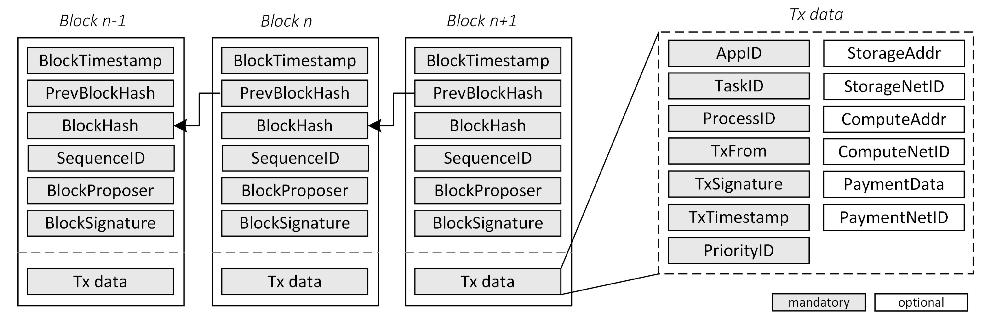
We use a custom block and transaction data structure in the Core Engine as shown in
Figure 2. The block headers are pretty straight forward, as they are commonly available in any blockchain data structure. It includes the timestamp of which the block is generated, the reference of the previous block, the hash of the block, the sequence identifier (for the PBFT consensus), the public key of the block proposer, as well as its corresponding signature. On the other hand, the transaction parameters are quite different as our blockchain is more tailored to the IoT environment. They may comprise the following:
AppID, the IoT application unique identifier in our architecture. During registration of the IoT applications in our architecture, the system assigned a unique identifier to each of the applicants.
TaskID, the application-defined task identifier. It is a useful parameter to distinguish types of IoT operations within the IoT application.
ProcessID, another application-defined unique identifier to distinguish one IoT process from another within the IoT application.
TxFrom the public key address of the sender of this transaction.
TxSignature, the digital signature of the sender.
TxTimestamp, the timestamp in which the transaction is generated.
PriorityID, the priority tag for this ProcessID. We use this information to implement Quality-of-Service (QoS) in the Core Engine (more details can be found in
Section 5.3).
StorageAddr, a parameter to indicate the pointer to the IoT data used in this ProcessID.
StorageNetID, when sub-engine parallelism is enabled, this parameter indicates the network identifier for the respective Storage Engine.
ComputeAddr, a reference to the correponding smart contract address for this ProcessID.
ComputeNetID, the same as StorageNetID but for Compute Engine.
PaymentData, any payment related data that need to be executed in the Payment Engine for this ProcessID.
PaymentNetID, the same as StorageNetID but for Payment Engine.
Note that the IoT apps may also include any arbitrary application-defined IoT data inside the transaction. We omit this data in our figure because this information may vary across IoT apps according to their use cases.
For achieving consensus in the Core Engine, we adopt the Practical Byzantine Fault Tolerance (PBFT) consensus algorithm. Our decision in choosing this algorithm is based on its high-performance metrics, which can process requests in high throughput with a limitation trade-off on the number of nodes that can join the network. This algorithm also requires nodes to know each other beforehand to discover the number of nodes in the network, which is an important parameter to determine the number of required approved messages in the algorithm. As a consequence, the network becomes a permissioned blockchain. Thus, we have to put a strict limit that only legitimate Notary nodes are allowed to sign transactions and propose blocks in the Core Engine.
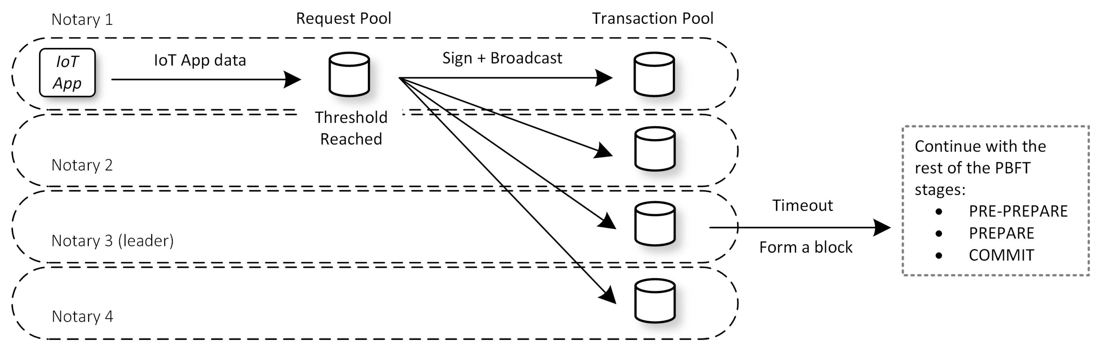
The block generation procedure in our Core Engine is as follows. First, the Notary node receives the IoT app data from IoT apps. The node then signs this data and broadcasts it as a transaction in the core network. When receiving a broadcasted transaction, other Notary nodes store it temporarily in a transaction pool. All of the Notary nodes have previously agreed on a single leader. If it is the time to propose a block, the leader forms a block by including transactions from his transaction pool to a block with an ordered Sequence ID. He then broadcast the block to other nodes. This block proposal broadcasting procedure is equal to the PRE-PREPARE stage defined in the PBFT algorithm. Other nodes store broadcasted blocks temporarily in a block pool while waiting for confirmations to move to the next PBFT stage, the PREPARE and then, the COMMIT stage. Once all of the nodes finish with the COMMIT stage, they will persist a block with the same Sequence ID in their local database. Then, the cycle repeats with the leader proposing a new block for the next Sequence ID.
5.2. Request Signaturing and Aggregation
To ensure the security of each transaction in the Core Engine, senders have to sign every transaction they broadcast to the core network. The PBFT also endorse this idea by suggesting signing each of the broadcasted PBFT messages in the protocol. However, because signing and verification procedures are CPU-intensive processes, during our early benchmark, these two operations cause a bottleneck in our system. Therefore, we present two solutions. First, we provide two signature options that the system administrator can choose depending on their use cases.
Symmetric Key, for example, Hash-based Message Authentication Code (HMAC). This procedure produces faster CPU performance than using the asymmetric key. However, the caveat is that we have to deploy this strategy in a more trusted environment. When a malicious message is found in the system, we cannot pinpoint the source of the message since all nodes that share the same keys can generate the message.
Asymmetric Key, for example, Edwards-curve Digital Signature Algorithm (EdDSA). With this option, we get a stronger non-repudiation guarantee. Thus, we can solve the problem mentioned in the previous option easily. However, it has a slower performance compared to the symmetric approach.
Second, we limit the number of signing and verification operations that the Notary node has to perform during the broadcasting of transactions and generated blocks. We introduce a Request Pool (RP), which saves incoming IoT app data requests from IoT apps temporarily, instead of directly broadcasting them to peers, as shown in
Figure 3. Once the size of the pool reaches a given threshold, the Notary node aggregates these requests into a single transaction. The node then signs and broadcasts this transaction to peers. We hypothesize that as we increase the pool size, the system will have lesser operations to sign and verify requests. Thus, increasing the overall throughput of the system.
Even though setting a higher threshold value for RP may increase the performance, setting it high at all times can be sub-optimal. Consider the following scenario where we set the RP pool size to be 500 requests. First, there is a flow of 50 requests per second lasting for 9 s. After that, that traffic stops, and another flow comes in with the rate of 1 request per second. The previous 450 requests carried out by the first flow will not be broadcasted and included in the blockchain before the RP threshold is full. Following the rate of the second flow, those requests will be processed in the next 50 s, which is a long delay. We eliminate this problem by creating an algorithm that detects the incoming flow rate to the system. Then, we can set the size of the RP dynamically to match the incoming requests.
5.3. Request Prioritization
We argue that there will always be a limit on how many IoT app data requests that the Notary node can process in the Core Engine. During high traffic, the system can be overloaded and start rejecting requests. Without a QoS policy, the Notary node can eventually drop very important requests and may result in worsening its current overloaded condition.
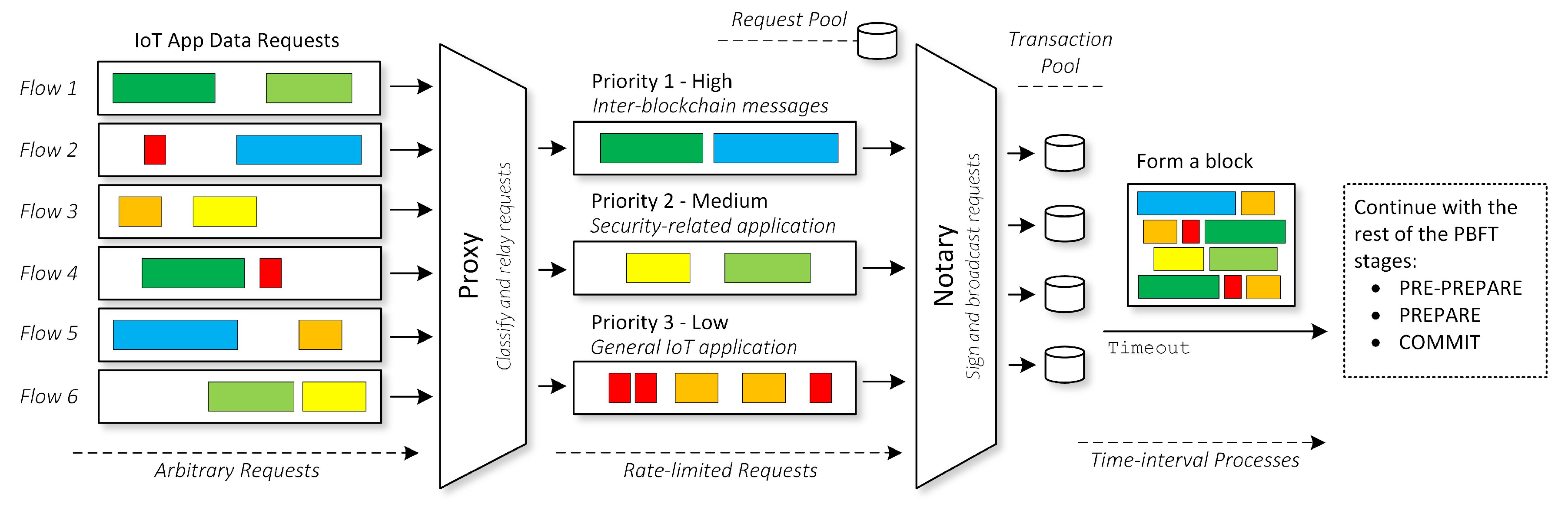
Figure 4 illustrates our request prioritization strategy to tackle this issue.
We define three priority types—high, medium, and low priority. We label high priority messages with Priority 1. The messages that fall into this category are inter-blockchain requests, operations that the Notary node has to perform across multiple sub-engines. Moreover, we divide the IoT applications in our architecture into two types: security and non-security application. The security related application takes precedence over the non-security one by using the medium priority type with Priority 2. The non-security related application uses the lowest rank of priority, which is Priority 3.
To enforce the priority mechanism, we introduce a new instance that we call the Proxy node. This node will relay requests from IoT apps to Notary nodes. In other words, all of the requests going to the Core Engine have to go through the Proxy node. At any given time, IoT apps can send arbitrary IoT app data requests to the Proxy node. The Proxy node receives and classifies all of these requests based on their priority identifier, then stores them in an internal temporary database. The node then periodically transmits all of these pending requests to the Notary node, following a rate limiter policy. Eventually, these requests will land in the request pool of the Notary node, then the Notary broadcasts them to other Notary nodes and finally, they are included in the block.
The Algorithm 1 shows the transmission policy in the Proxy node to relay requests that coming from IoT apps to Notary nodes. For starters, we have a pre-defined base multiplier, , in the form of a configurable softmax array. We also have , the maximum throughput that the Proxy node can send per second to a designated Notary node. With these two parameters, we can determine the maximum amount of requests per second for each priority type, , , and . In other words, we give slots to each of the priority type. , , and are the current number of pending requests in the Proxy’s database for Priority 1, 2, and 3 respectively.
The algorithm shows 8 cases to multiplex Priority 1, 2, and 3 without violating the given
threshold. However, we can simplify them into 4 common patterns. First, if all of the numbers of requests in the database exceeds our maximum throughput threshold,
, we limit the number of requests that we transmit to the Notary node. Otherwise, we just get all of the requests in the database without limit (
) and then send them altogether as shown in Case 8. Second, when all of the
,
, and
exceed
,
, and
, we get the requests by applying limit to all of the priority types (
). Third, if only two among
,
, and
exceeds its respective threshold, we assign the residual slot of the priority that does not exceed the threshold to the other priority types. The highest priority will take precedence in taking the residual slot over the lower priority one. This scenario happens in Case 2, 3, and 5. Lastly, when only one among
,
, and
exceeds its respective threshold, we assign all of the residuals to that priority. This scenario exists in Case 4, 6, and 7.
| Algorithm 1: Sending pending IoT app data requests to Notary nodes with prioritization. |
![Electronics 09 01050 i001]() |
5.4. Sub-Engine Parallelism
The purpose of the sub-engine parallelism is to bridge the performance gap between the Core Engine and the sub-engine. The Core Engine can process transactions in thousands, or even tens or hundreds of thousands request per second. However, the sub-engine can only process transactions in tens or hundreds of requests per second. Without parallelism, then the overall performance of our architecture is capped at the bottleneck sub-engines.
For example, among other sub-engines, our Compute Engine, which is based on Ethereum, is most likely to be the bottleneck in our architecture. The public Ethereum network can only process about 15 Tx/s. Without parallelism, then we cannot maximize the potential of our Core Engine because the engine will spend most of its time waiting for the Ethereum network to process the data. In contrast, if we have a hundred instances of Ethereum network running in parallel, we can achieve roughly 1500 Tx/s, which is a significant improvement. Note that this metric will remain true as long as the majority of the Compute Engine process happens locally inside the sub-engines.
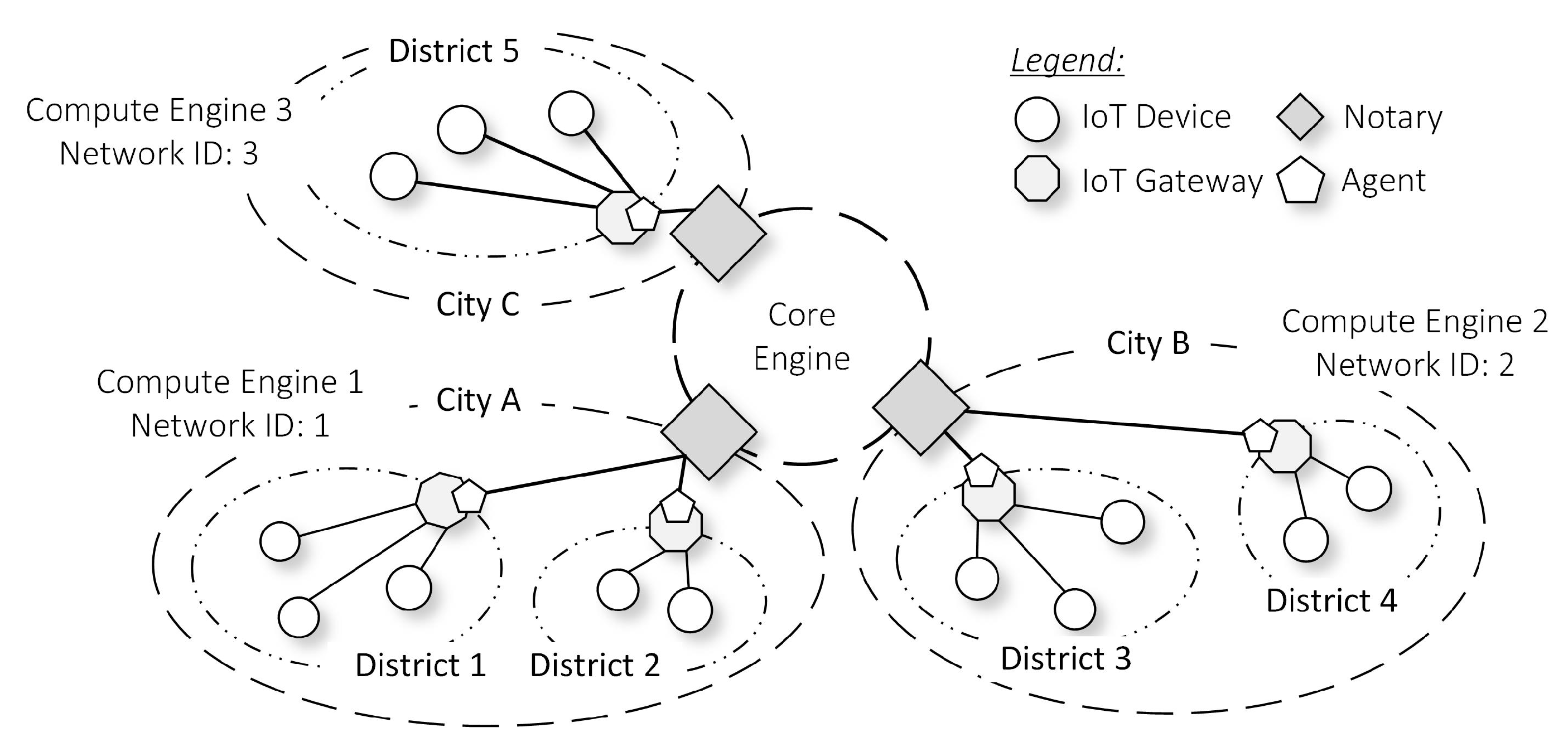
The sub-engine parallelism concept can be applied to all of the underlying sub-engines. However, for the sake of simplicity, in
Figure 5, we only show the parallelism in the Compute Engine. During parallelism, each of the Compute Engines is identifiable by a parameter called Network ID. A Notary node and Agent nodes manage a particular Compute Engine in a city independently from other nodes in different cities. Furthermore, we have a requirement to designate at least one Notary node to govern a particular parallel sub-engine. The Notary node can only connect to a few (but not all) of parallel sub-engines. Having all of the Notary nodes manage all of the parallel sub-engines is counterproductive, as it will disregard the locality benefits of the parallelism.
Since parallel sub-engines are isolated from one another, the state of a Compute Engine in one city is independent of others currently running in a different city. Therefore by default, Agent nodes and users in one city are isolated and cannot understand the state of the Compute Engine in other cities. At these circumstances, Agent nodes are actually at an advantage because they do not need to consider storing the state of Compute Engine across the nation. They just need to focus on storing the local city-state where they operate, resulting in a lower storage requirement.
6. IoT Applications
In this section, we describe an example of how others can build distributed IoT applications on top of our proposed architecture. The application logic may vary depending on the actual use cases. Here we provide only a basic application scenario that leverages all of the proposed engines, as well as, the parallelism concept. For this purpose, we revisit the use case of an IoT-powered car rental application by reinventing the whole app ecosystem using our proposed blockchain architecture. This scenario facilitates a verifiable marketplace to match car renters to car owners through a car rental IoT app that is pre-installed in Notary nodes.
During network startup, the administrator already set up and run the required engines. In this example, we enable parallelism in the Compute Engine such that only Notary 1 connects to the Ethereum Virtual Machine (EVM) in the Compute Engine 1.
We assume that other Notary nodes connect to different Compute Engines with their respective network identifiers, and they do not have access to this Compute Engine 1. The rest of the sub-engines are not parallelized. All of the Notary nodes connect to the same Storage, Payment, and Core Engine.
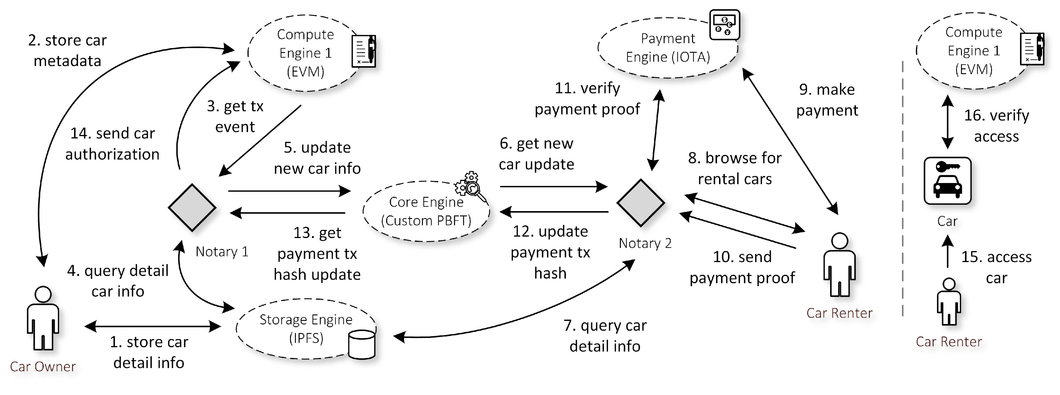
Figure 6 summarizes the application logic of the car rental app. We elaborate more in the following paragraphs.
To put his car on the lease, the car owner first has to produce detailed information about his car. This information may include car parameters such as car manufacturer name, car model, car color, car license, car production year, and car transmission type. It also includes payment information such as the IOTA payment address, IOTA payment tag, and IOTA payment fee. He then stores all of this information in the Storage Engine. By doing so, he will get an IPFS hash as proof of successful storage. Note that, this IPFS hash also serves as a car identifier throughout the application.
The car owner then sends the IPFS hash as a car metadata to the Compute Engine 1. Specifically, the car owner forms a transaction to a legitimate Ethereum smart contract, which the IoT app previously issued. He will then obtain the transaction (tx) hash as proof of a successful transfer. Note that, at each of the Compute Engines, Notary nodes may deploy multiple smart contracts, for example, one contract per IoT app. Thus, the car owner has to make sure that he contacts the correct smart contract that this car rental app issues. Moreover, since we enable parallelism, the car owner also needs to communicate with the smart contract in the correct compute network ID where his car will operate. In this case, it is the Compute Engine 1.
In general IoT app, the car owner has to submit his car information to the IoT app directly. However, using our architecture, after submitting his car info in both Storage and Compute Engine, the car owner does not need to submit a single request to the IoT app. During the initial network deployment, the car rental application previously subscribed to all events from his smart contract. Therefore, the app can receive a ’New Car Inserted’ event as a result of the car owner’s execution in this previous step. This event informs the IoT application the IPFS hash of the car, as well as the Ethereum address of the car owner.
The app then has to make sure that the car owner sends valid car metadata in the Compute Engine. Therefore, the app has to cross-checks the metadata with the detail information in the IPFS network.
When everything is valid, the app updates his local database with this new car owner information. The app then broadcasts this information to the Core Engine to let other application instances, residing in different Notary nodes, to be aware of this new information. Specifically, the app sends the following parameters.
AppID, each of the apps in our architecture has its globally unique ID.
TaskID, the app can define a unique TaskID to differentiate between tasks. For example, the TaskID of 1 indicates the new insertion of a car from the owner. Thus, other instances can determine instantaneously what to do upon receiving this Task ID.
ProcessID, every update to the Core Engine will have a distinct ProcessID.
StorageAddr, the IPFS hash as car identifier.
ComputeAddr, the smart contract address in which the IoT app receives the previous ‘New Car Inserted’ event.
ComputeNetID, the network ID of the Ethereum network. Because we apply parallelism in our Compute Engine, we have to specify this information as complementary materials.
Note that IoT apps can send arbitrary data to the Core Engine to synchronize their states among Notary nodes. Therefore, the data structure in the Core Engine may vary from one app to another. However, the AppID, TaskID, and ProcessID are the mandatory items to be put in the Core Engine.
Another IoT app instance in the Notary 2 receives the new car update from the previous step through the Core Engine.
Using the obtained IPFS hash, the app queries details of the car info from the Storage Engine. If he has not seen this information before, the app then updates his local database accordingly. Alternatively, the app instance in the Notary 1 could include the car detail information during the Core Engine update in Step 5. Thus, the app instance in the Notary 2 does not need to query the info in the IPFS network. However, this approach has a consequence that the second instance has to fully trust the first instance such that it sends only accurate and not malicious information.
At any given of time, the car renter can browse for an available car for rent through the IoT app. He can obtain the IPFS hash, payment address, payment tag, payment fee, car model, car year, and other car parameters. Note that, he can optionally cross-check the validity of this information by querying the detailed info in the Storage Engine, as well as the metadata info in the Compute Engine. In this example, let us assume that the car renter picks the car owner’s car.
Using the previously obtained information, the car renter makes a payment to the designated IOTA address owned by the car owner. Once the payment completes, he retrieves the tx hash as a proof of payment.
The car renter then submits this tx hash back to the IoT app. At this step, the car renter also specifies the Ethereum address that she will use to access the car in the later step.
The IoT app now has to verify the submitted tx hash. First, he has to make sure that he never see this payment hash before (no double spent). All of the IoT applications installed in the Notary node can have access to a shared database containing lists of approved payment tx hash. The basic idea is that a payment tx hash can only be used once. If the apps find that the submitted tx hash from car renter exists in the database, it can imply that he tries to perform double-spending. Second, the apps have to make sure that the tx hash is valid in the IOTA network. Specifically, he has to make sure that other IOTA nodes have approved the tx hash. Finally, the tx hash also needs to contain correct information (i.e., the fee amount, fee address, and fee tag) as the one that the car owner proposed.
When the payment verification is successful, the app updates its local database to change the status of the car to be rented to the respective car renter. He also updates the shared database to include the recently obtained payment tx hash. Thus, future requests cannot use this hash anymore. While checking his local database, he realizes that he cannot connect to the Compute Engine to process this step further due to parallelism. He concludes that other Notary instances may have access to the Compute Engine. Therefore, he sends this tx hash to the Core Engine to let other apps aware of this update. Specifically, the app sends similar parameters as the one in Step 5 with minor modification. The TaskID now uses the TaskID of 2 that indicates payment confirmation for car renter. Also, we add two additional parameters, the PaymentData, filled with payment tx hash, and the CarRenterAddress, which is the address that the car renter submits previously in Step 10.
Upon receiving updates from the Core Engine, the app updates its local database to change the status of the car into ’rented by the car renter’. The app also saves the payment tx hash in the shared database.
Then, the app sends car authorization for the car renter to the smart contract. More specifically, the apps update the car information to have the CarRenterAddress as its authorized renter.
The car renter can subscribe to the smart contract to get events when the IoT apps give authorization access to his previous request. Upon receiving such an event, the renter signs an authenticated message to the car with his private key that corresponds to the Ethereum address that he previously registered in Step 10.
The car receives the message and validates that the signature by comparing the data in the Compute Engine 1. When the car finds that the signature belongs to the legitimate Ethereum address that has the privilege to rent this car, he will let the renter access the car.
We would like to close this section by mentioning the benefits of deploying IoT apps in our architecture.
Instead of sending the car information directly to the IoT apps, the car owner has to ’anchor’ the data by storing the contents in the Storage and Compute Engine. Similarly, the car renter also has to make payment to the Payment Engine instead of paying directly to the IoT apps. The benefit of this ’anchoring’ approach is that we lower the centralization power of the IoT app to censor the users (i.e., the car owner and car renter). In case of disputes, assuming that the underlying sub-engine blockchain network remains secure, the car owner and car renter can present his portion of the stored data in the sub-engines as pieces of evidence [
18].
The users are in control of their data. For example, by adding a signature in the car data stored in the Storage Engine, other users can easily verify that the car owner is the true origin of particular car information. The IoT app then cannot maliciously tamper the car data. Moreover, using a proxy re-encryption [
19], the car owner can encrypt his data and assign the decryption key only to the party that he desires. Thus, adding confidentiality attributes to the data.
Other developers can indeed deploy a similar car-rental scenario using only one network, say an Ethereum network. However, the current Ethereum network has scalability issues. Our architecture provides the parallelism (or sharding mechanism) for the underlying sub-engines so that they can perform as locally as possible and, in result, increasing the overall performance.
Finally, the use of sub-engines can also serve as a data backup mechanism for the IoT app since it is more reliable to store the data distributedly across the network rather than saving it in a centralized database in the IoT app side.
7. Implementation
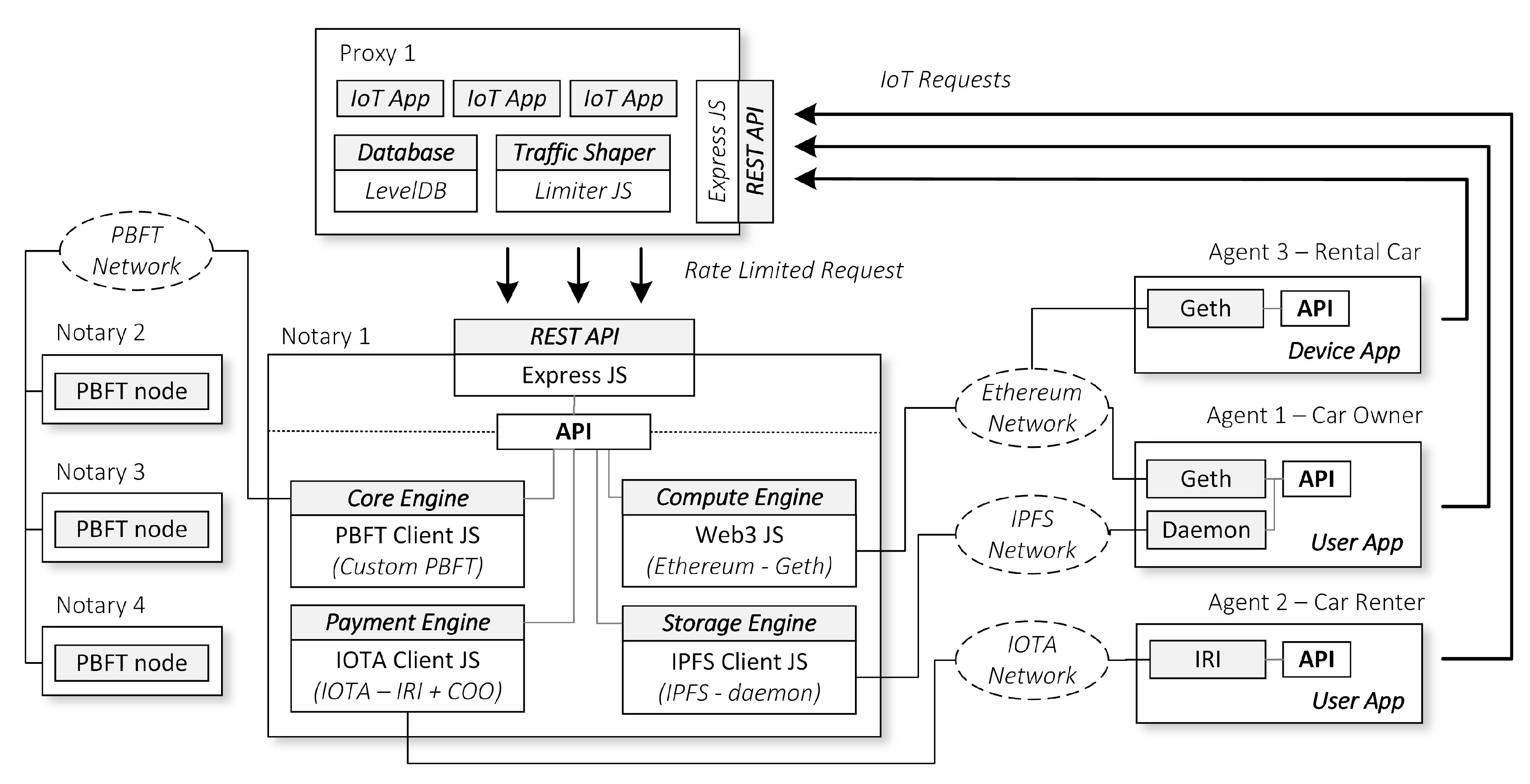
As we show in
Figure 7, most of our implementations are based on Node JS applications scattered across three types of instance, the Notary, the Proxy, and the Agent node. We build our engines in a private network environment with each of the nodes reside in a separate local Virtual Machine (VM). We have set up the app instances in the Notary and Agent nodes to use our API to connect to the respective engines. We describe the details of our API implementations as follows.
Payment Engine API. The Notary node is a full IOTA node or IOTA Reference Implementation (IRI) node [
20]. Meanwhile, the Agent node can run a lightweight version of the IOTA node since some of the Agents may not have the necessary resource to run the full node. We build a private IOTA (Tangle) network among Notary and Agent nodes. Additionally, one of the Notary nodes acts as an IOTA coordinator (COO) node [
21] that will create milestones to stabilize the network. The app instances, in the Notary or Agent nodes, can use our API to communicate to the Payment Engine. This API is based on the IOTA Javascript (JS) client implementation [
22].
Storage Engine API. We install IPFS daemon node [
23] to each of the Notary nodes and Agent nodes. Then, we construct a private IPFS network among them. One of the Notary nodes acts as a bootstrap node, and the rest of the nodes will connect to this particular node during startup. The app instances can communicate to the Storage Engine through our API, which is based on IPFS JS client implementation [
24].
Compute Engine API. We setup Notary nodes to become full Ethereum nodes using Geth [
25]. Meanwhile, the Agent nodes may run in a lightweight node when necessary, depending on the resources that they have. Thus, Notary nodes can do the mining, while the Agent nodes are ordinary nodes that only sends and retrieves transactions. Then, we apply a custom genesis block to create our private Ethereum network among Notary and Agent nodes. The app instances contact the Compute Engine through our API that is based on the Web3 JS [
26].
Core Engine API. Finally, for the Core Engine, we apply our custom PBFT node based on Node JS. IoT apps can use this PBFT module to synchronize our IoT app data across distributed Notary nodes. Note that only Notary nodes can connect to the Core Engine, and the authentication is required upon joining the Core Engine.
The Proxy nodes exist to relay communication from the Agents to the Notary nodes. This node is a complementary node to do specialized tasks such as load balancing and Quality of Service (QoS) based on IoT requests priority. The nodes have a REST API module based on Express JS [
27] to implement the REST API endpoints. It also uses a LevelDB [
28] as a local database to store temporary requests from the Agents before the Proxy nodes forward the request to the Notary nodes. When relaying the messages, the Proxy uses a token bucket rate limiter algorithm based on Limiter JS [
29].
Note that, in this example, we separate the Proxy nodes and Notary nodes in different VMs. However, the Proxy and Notary node can also reside in a single machine if it is preferred by the administrator. Moreover, we originally install the IoT apps in the Notary node. But when we use a Proxy node, the IoT App will reside in the Proxy node instead.
8. Evaluation
In this section, we share our experiment results in developing the proof-of-concept of our proposed hierarchical multi-blockchain architecture for IoT. We begin by evaluating the Core Engine performance and then assessing the integration of the sub-engines to the Core Engine by following the application logic of our IoT car rental application.
8.1. Core Engine Evaluation
8.1.1. Static Request Pool Mechanism
Setup. We deploy four Notary nodes that run the Core Engine inside four Virtual Machines (VMs) in our private server. We use Oracle Virtual Box VM [
30] with the configuration of 1 CPU and 2048 MB of RAM for each of the Notary nodes. The CPU specification of the host machine is Intel(R) Xeon(R) Gold 6136 CPU @ 3.00 GHz and the RAM is Samsung DDR4 2666 MHz.
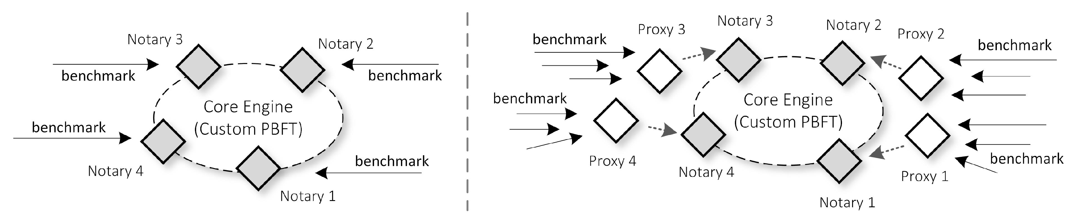
In our core network, we set up our Notary nodes to propose a block every 1 second. After the engine is running, we run Autocannon [
31], an HTTP benchmarking tool, to stress the engine. More specifically, we create four Autocannon instances that perform stress tests to all of the Notary nodes, one instance for one Notary node, as shown in
Figure 8 left. The nodes accept the Autocannon requests and simultaneously broadcast the requests while also propose and broadcast blocks containing the accepted requests. For this scenario, we tweak the Autocannon to send a total of 1,500,000 requests, which is an expected number of IoT requests that one gateway may receive in a day, following the ITU-T first year planning [
32]. We divide them equally, therefore each of the Notary nodes processes 375,000 requests. Moreover, we run this scenario five times by changing the Request Pool size of the Core Engine each time we start the benchmark. We then record the throughput and latency results of the Autocannon in
Table 1 and
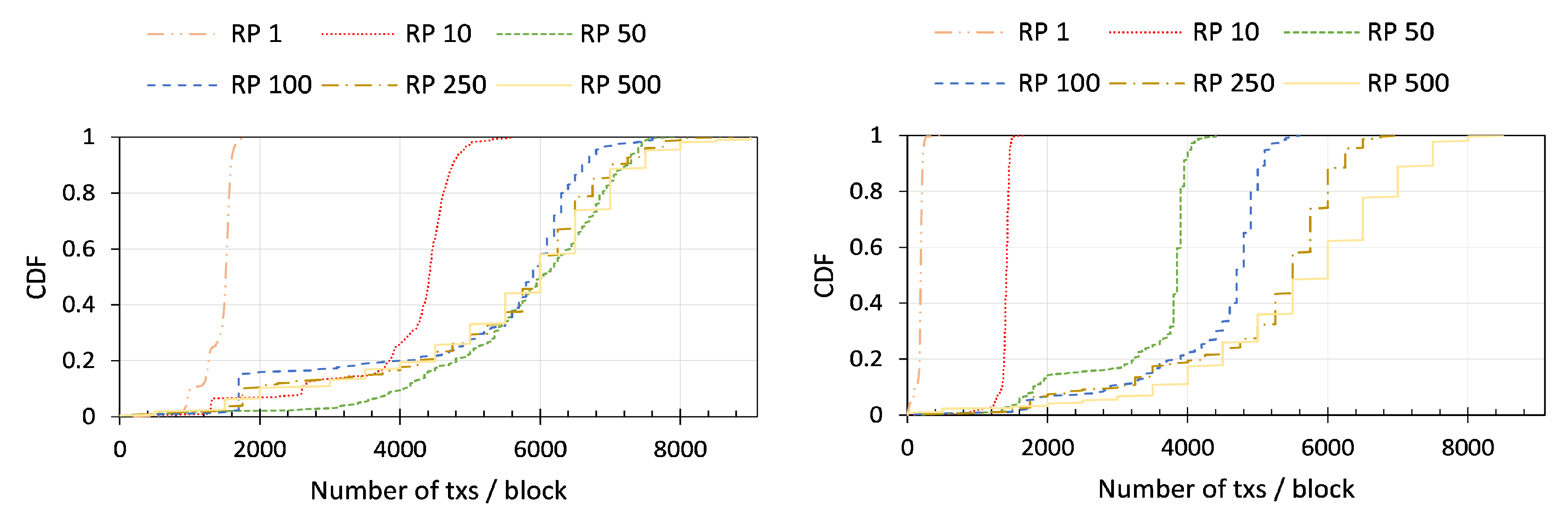
Table 2 respectively. We also measure the Cumulative Distribution Function (CDF) of the number of requests (or transactions) that has been included in each of the generated blocks, shown in
Figure 9.
Varying the Request Pool (RP) size means that a Notary node has to wait for x number of requests before he aggregates those requests into a single transaction, then signs it using HMAC or EdDSA depending on the case, and broadcast it to other nodes. Following this logic, with RP 1, the node just needs to wait for only one request before it signs and broadcast, which is equivalent to having no RP mechanism at all. Therefore, this serves as a base-line to quantitatively compare the effectiveness of our RP strategy.
We can see from our result in
Table 1 and
Table 2 that, across all of the scenarios, setting a higher threshold on the RP size increases the throughput and decreases the latency of the Core Engine. The EdDSA scenario is the one with the most improvement with 33 times increase of the throughput and 37 times decrease of the latency by changing the RP size from 1 to 500. We can confirm this trend by investigating the CDF for the recorded number of transactions per block in
Figure 9. In that figure, we can see that RP 500 includes more transactions than RP 1 with a significant gap. Because of signing and verifying the asymmetric digital signature requires high CPU computation, with the use of our RP strategy, we can reduce the frequency of those operations so that we can increase the overall performance.
8.1.2. Dynamic Request Pool Mechanism
Setup. To assess the effectiveness of setting the Request Pool (RP) size dynamically, we use the topology in
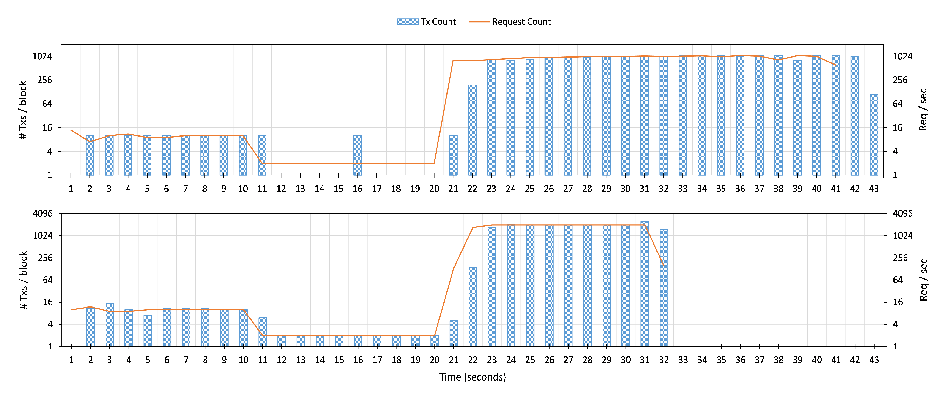
Figure 8 left. However, instead of sending Autocannon instances to each of the Notary nodes, this time we only target one Notary node. We configure the Notary nodes to use the EdDSA signature mode. After that, we create three Autocannon instances. First, we send 100 requests with a fixed rate of 10 requests per second. Second, we transmit 20 requests using a decreased rate of 2 requests per second. Finally, we boost the instance by delivering 20,000 requests with 2000 requests per second. We run these instances alternately, the next instance runs automatically right after the previous one completes.
In our first scenario, we set the RP size to 10 and disable the dynamic configuration. We then run the Autocannon instances and plot the request count, as well as the number of transactions in the block in
Figure 10 top. The first flow begin from
to
. Because the number of requests matches the RP threshold, the Notary node does not find any difficulties in including these requests as transactions in the block (from
to
). However, in the second flow, from
to
, the·rate of the request is decreased to only 2 requests per second. The Notary node does not broadcast the received requests until the RP threshold is full. Therefore, some requests experience a delay for the worst case of 5 s until the requests are included in the block at
and
. Lastly, the third flow tries to transmit the rate of 2000 requests per second starting at
. However, due to the limitation in the performance of signing and verifying EdDSA signature as presented in the previous section, the Notary node can only process about 1000 requests per second, resulting in a longer completion time (22 s, from
to
).
In our second scenario, we set the RP size to 10, and this time we enable the dynamic RP reconfiguration.
Figure 10 bottom depicts the request count, as well as the number of transactions in the block. The behavior for the first flow is similar to the previous scenario. However, in the second flow, from
to
, the Notary node now can detect that the incoming request rate is decreasing and start to apply a lower RP threshold size of 1. Therefore, the node can include the requests in the block without any delay from
to
. Finally, the node starts increasing the threshold again to 500 when it detects the incoming request rate increase at
. With this high RP size, The node can accept more requests (about 2000 request per second) compared to the previous scenario, resulting in a faster completion time (10 s, from
to
). This experiment shows that our Notary node can adapt to the variation of IoT app requests so that it can effectively configure the RP size accordingly. Thus, avoiding long delay and decreased throughput that happen in the first scenario.
8.1.3. Priority Mechanism
Setup. We use the same configuration for the Notary nodes VM as our previous benchmark in
Section 8.1.1 and set the Request Pool size to 100. We then add four Proxy nodes, each of them resides in a separate VM with the configuration of 1 CPU and 1024 MB of RAM. All of the Proxy VM instances are all in the same host machines as the Notary node VMs. Thus, we deploy 8 VMs in total. We create a one-to-one mapping topology between Proxy and Notary nodes, as shown in
Figure 8 right. Therefore, one Proxy node will forward the requests from Autocannon instances to only one Notary node.
We create three Autocannon instances for each of the Proxy nodes. One instance contains only high priority flows (Priority 1), another one is to simulate medium priority flows (Priority 2), and the last is for low priority flows (Priority 3). In total, we create 12 instances. From the ITU-T IoT use case in their first year planning [
32], we can expect that we need to process a total of 15,000,000 requests over 10 gateways in a day. We import this number into 12 Autocannon instances, so one Proxy node will receive 3,750,000 requests with 1,250,000 requests for each of the priority flows.
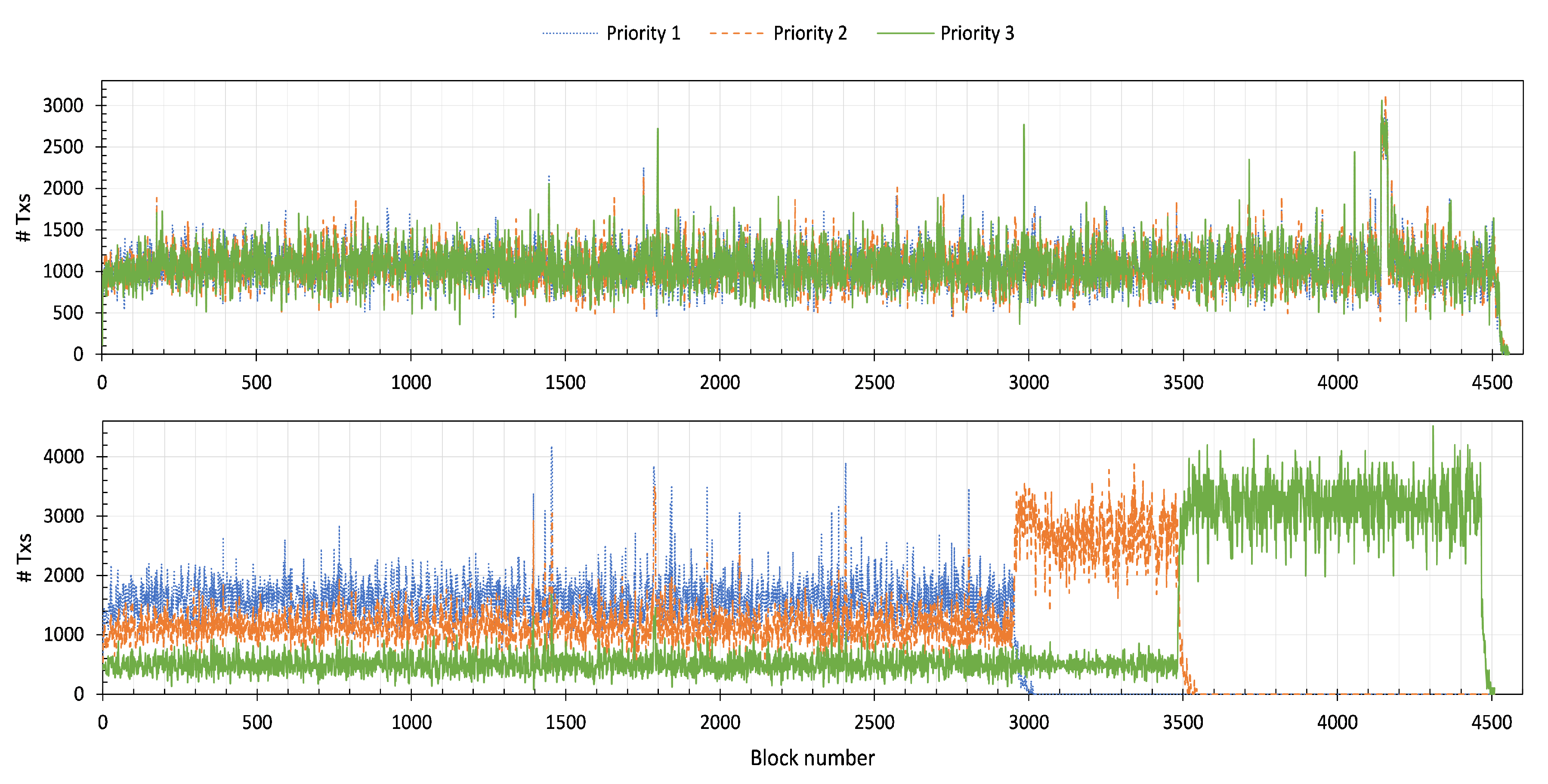
No Priority. When we disable the priority algorithm, the Proxy node distributes received requests from Autocannon instances equally to the designated Notary node. Among the maximum traffic allowance to a Notary node, the Proxy fills 33.33% percent of it with requests that have Priority 1 tag, 33.33% with Priority 2, and the last 33.33% with Priority 3 tag. Once the benchmark finishes, we query the number of transactions per block per Priority tag. We then plot them in
Figure 11 top. We can see from the figure, that the flow for Priority 1–3 are overlapping one another, showing that Proxy nodes indeed have distributed the requests equally to the Notary nodes.
With Priority. Similar to the “No Priority” benchmark, we plot the number of the included transactions per block in
Figure 11 bottom. When all the flows from Priority 1–3 are present, the Proxy node prioritize Priority 1 more than the other. We can see this behavior in the first 2950 generated blocks. During this period, we have more Priority 1 transactions in the blocks compared to the Priority 2 and 3.
When the Proxy node finishes sending particular Priority flows, it assigns the slot for that flow to the next highest Priority flow in the list. Therefore, we can see that the number of Priority 2 transactions rises from block number 2950 to 3500. At this time, the Proxy has completed delivering Priority 1 messages. The same tendency happens at block number 3500. At this point, we have no Priority 1 and 2 to send left. Therefore, the Proxy uses all the slots to send Priority 3 messages.
8.2. Cross Engines Evaluation
The main concern of our proposed architecture is the latency across core and sub-engines, especially when we have a worst-case scenario where a particular flow of an IoT application logic has to go through multiple engines before it completes. To analyze this scenario, we construct a simulation of our IoT car rental demo application that we described in
Section 6. We developed the application logic, shown in
Figure 6, in the form of an IoT app in the Notary node. We also create the car owner, car renter, and car object as application instances in the Agent nodes. Our deployment scenario is similar to the
Figure 7. However, we remove the Proxy node. The Agents are directly connected to the Notary node instead, and the IoT apps are installed in the Notary node.
For this scenario, we have 4 instances of Notary node, each of them has 4 CPU cores and 8192 MB of memory. We also have 3 Agents node that includes car owner, car renter, and car backend with each of them having 1 CPU core and 4096 MB of memory. Thus, we deploy 7 VMs in our local network. Once we set up the network, we run our scenario 1000 times. Then, we measure the average latency, as well as the standard deviation, and present them in
Table 3.
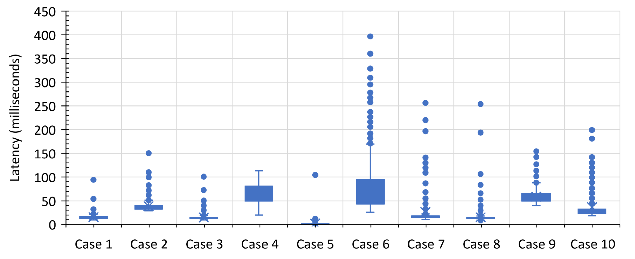
Figure 12 summarizes the box plot of our latency measurements.
Overall, we can complete all of the steps in this scenario in less than 459.09 ms for at least 90% of the time. The fastest latency happens in Case 5, which is at most 1.94 ms for at least 90% of the time. We expect this behavior because it is the simplest case among all. It is just an HTTP request to the IoT app that also includes a query for car info in the local database. Meanwhile, the longest delay happens in Case 6, which hit at most 141.47 ms for at least 90% of the time. This case responsible for sending payment transactions to the IOTA network. In this process, the system has to find a tip, conduct a proof-of-work for the transactions, then broadcast the transactions to the network. We conjecture that all of these processes are complex and stochastic processes, especially the proof-of-work mechanism. Therefore, we see longer delays in this step and we have high variance as well. Finally, even though we run all of these scenarios in our local network. The car rental scenario involves communication across multiple overlay networks that is physically separated across local VMs. Therefore, we still expect to see some anomalies such as a high number of latencies in our simulation.
9. Discussion
In this section, we present multiple related works on multi-blockchain architecture and elaborate on how our architecture differs from them. We also bring up a discussion on the deployment strategy that adopters might have to do in the production scenario.
9.1. Related Work
There are several hybrid blockchain architectures for IoT that arise in the literature. They all have a similar design pattern to our proposal, the presence of a central network that glues multiple sub-blockchains into a single coherent blockchain architecture.
The authors of Reference [
33] tackle the blockchain scalability issues in IoT by proposing a hybrid blockchain architecture. Notably, they divide the blockchain network into multiple sub-blockchain networks. In one sub-blockchain, IoT devices gather and form a PoW-based blockchain network. Then, a BFT inter-connector framework such as Polkadot or Cosmos governs the connection between multiple sub-blockchains. The authors present detailed investigations on the PoW internal re-parameterizations in their sub-blockchain infrastructure, which we can take as a “lesson learned” and apply it into our sub-engines. However, the authors do not mention the BFT inter-connector part and leave it as a future work instead. On the other hand, our architecture shows the use case of inter-connection between blockchain, as well as the sub-engine parallelism mechanism through our IoT rental car application.
The authors of Reference [
34] argue that one IoT application may have different requirements from other applications. A single general blockchain is not suitable for IoT because there is no one-size-fits-all solution. To overcome this issue, the authors break the blockchain into several sub-blockchains based on IoT use cases. This separation aims to efficiently target blockchain usage to its fullest as IoT adopters can now use any blockchain that suits their use case the most. Finally, one consortium blockchain manages all of the available sub-blockchains and acts as a control station for the whole blockchain network.
IoTeX [
35] proposes a comprehensive blockchain-based decentralized architecture for IoT. The team designs their project to guarantee two properties—scalability and privacy. They propose the use of multiple sub-chains, one per IoT use case, a similar idea to the previously mentioned study. A single root-chain governs these sub-chains and provide relaying service from one sub-chain to another. To realize this goal, they also propose a novel consensus algorithm called Roll-DPOS [
36]. While the blockchain provides built-in privacy through pseudonymity, the authors argue that it is not enough for IoT use cases. Therefore, they propose the use of stealth addresses, ring signatures, as well as Pedersen commitments to achieve full anonymity on the blockchain transactions.
Compared with these two proposals, we divide our sub-blockchain based on its role (i.e., Compute, Storage, and Payment Engine) instead of its use case (e.g., healthcare, industrial, and smart home). We believe that separating this way can render better usability, as we can view our architecture as a framework in which developers can enforce standards on the platform in the form of engine APIs. We can also control the importance of IoT applications by its use case. For example, we put a higher priority on security-related IoT applications. This scenario is possible because we have a coherent API.
LSB [
37], an acronym for Lightweight and Scalable Blockchain, is another study that integrates multiple blockchain networks into a single architecture. The most exciting aspect of this research is the fact that the authors build a customized blockchain explicitly tailored for IoT. They propound the use of two blockchain networks. First, a local blockchain exists on each of IoT domains, with the presence of a single gateway serves as a central authority that mines the blockchain solely. This gateway also acts as a policy enforcement module that will intercept all IoT messages and allow only authorized access based on the information from the policy header in the local blockchain. Second, an overlay blockchain network oversees the communication between IoT domains. Several cluster heads form groups of IoT domains and conduct a consensus among themselves using a Distributed Time-based Consensus algorithm. While the idea is promising, we argue that this study has to undergo feasibility and usability testing before anyone can begin adopting the architecture. On another hand, our proposal is based on the combinations of community-based blockchain projects. Developers had put much time and effort into the testing of our underlying projects.
9.2. Deployment Consideration
Core Engine Improvement. We have to mention that the throughput evaluation results in
Section 8 can be increased further if we apply multi-threading in our Core Engine. However, since our implementation is based on Node JS, which is a single-thread, we currently have not conducted this experiment. Moreover, we find that the crypto library in Node JS is very slow compared to other libraries in other programming languages. This issue causes a significant performance drop between the HMAC and EdDSA. Therefore, in the production scenario, we can consider change the programming language of the current Core Engine to other higher performance programming languages such as C++ or Go. The rationale in choosing Node JS in this paper is due to the authors’ familiarity in the language, and we argue that changes in the language should not omit the benefits of our proposed request aggregation, prioritization, as well as sub-engine parallelism strategy.
Node Specification Requirements. The CPU (or GPU) requirements depend on whether the node has to perform Proof-of-Work (PoW) or not. If a node needs to do PoW, then the required resources will depend on the difficulty level of the network. For the memory requirements, the IPFS recommends a minimum specification of 2 GB of RAM. Meanwhile, IOTA recommends using 4 GB of RAM. The RAM requirements for the Ethereum network depends on the current DAG size of the network. The DAG size keeps increasing as we add more and more blocks to the blockchain. For example, the DAG size of the current public Etherum network is about 3.62 GB.
Based on those suggestions, we can consider the following production scenario. For all of the sub-engines, Notary nodes have to become the full node. Developers have to experiment with the number of CPU, GPU, and RAM that Notary nodes should have, depending on the number, the type, and the parameters of sub-engines in the production network. After that, Agent nodes can start by performing the role of a light node, and only become a full node when they met the resource requirements. IoT devices can act as outsider nodes, which rely on Agent nodes to process all of the sub-engine processes on their behalf. Alternatively, IoT devices may also transform into a light node or even a full node when they can satisfy the requirements. Finally, all of the nodes should also watch for the size of the physical hard drive. The longer the network runs, the more space is required to store all of the blockchain data.
Increased Latency. During our latency measurement for our car rental application in
Table 3, we follow the following Equation (
1).
, , , and are the total app flow delay, the internal app flow processing delay, the network delay in the sub engine, and the network delay in the Core Engine respectively. Furthermore, m denotes the number of internal processes that this particular flow has to process. Meanwhile, n indicates the number of sub-engines that this flow uses.
In the production case, it is expected to have heterogeneity in the specs of the Notary and Agent nodes. Therefore, the will vary. Lower specs or if the system is under heavy utilization may increase the delay. We also expect to see an increased in the latency of the and because Notary and Agent nodes are most likely to be geographically distributed across the network. Furthermore, cooperation among other participants of the sub-engine network is also important. In the IOTA network, we depend on other nodes to extend our transaction in the Tangle so that our transactions can be valid. In the Ethereum network, we depend on the role of the miner to validate and include our transactions in the block. This is an external factor that we cannot precisely guarantee to result in low latency, as we see in our local simulation.
10. Conclusions
In this paper, we proposed a scalable hierarchical blockchain architecture for the IoT, comprising of one Core Engine and three sub-engines—Payment, Compute, and Storage Engine. All of them facilitated the execution of IoT application workflows under the Notary nodes and Agent nodes. We implemented a customized Core Engine based on PBFT protocol and proposed the idea of using requests aggregation and prioritization to efficiently boosting its performance. We also provided an initial proof of concept implementation to assess the feasibility of the cross-engine interoperability, as well as sub-engine parallelism execution in the form of an IoT car rental demo application. Our evaluation results showed that our proposal was doable and performed well in a local network environment.
In the future, we would like to investigate a scenario where Notary and Agent nodes are implemented across diverse types of devices, ranging from powerful server-grade computers, end-user computers or laptops, smartphones, and IoT devices (e.g., Raspberry Pi or Arduino devices). All of these devices would most likely be scattered geographically across the network. Moreover, currently, we designed the sub-engine parallelism concept statically and proactively. In particular, administrators had to setup parallel sub-engines at the beginning before running the network. Hence, we could try to deploy and/or turn off these engines on the fly depending on the current demands, and perform load balancing among sub-engines. Specifically, when one sub-engines became overload, we could transfer processes or nodes from one sub-engines to another.


