Alongside the analysis of architecture and the size of components, the critical factor in a TTR HEV is the vehicle control strategy [
15]. The satisfying control strategy needs essentially to achieve the control objectives such as: satisfy the driver’s power demand, reduce fuel consumption and emission, sustain a rational level of battery SOC for self-sustaining operation (no external charging), and regain the optimal amount of braking energy [
32,
33].
3.3.2. Electric Assist Control Strategy
The Electric Assist Control Strategy (EACS) represents a commonly used rule-based control strategy [
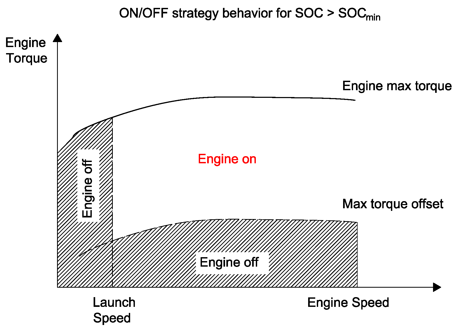
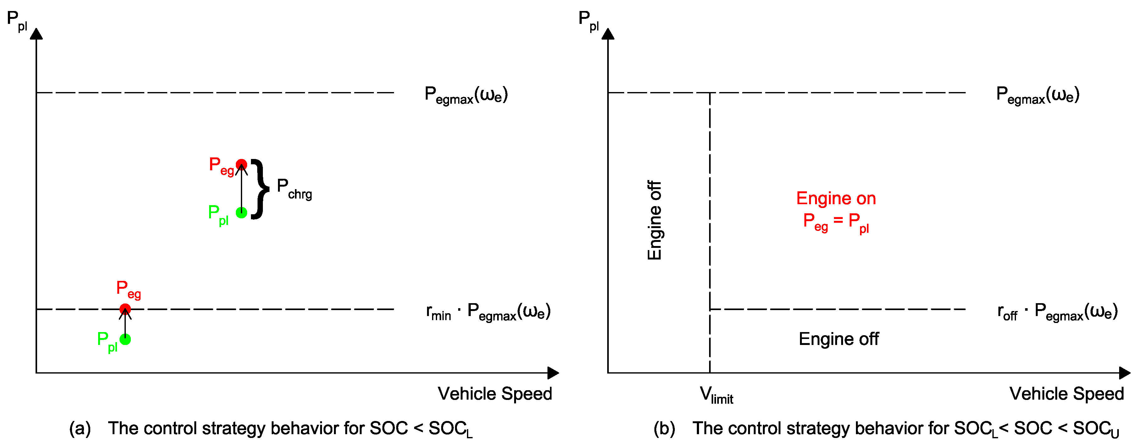
36]. It uses the ICE as the main power source and the battery to assist the ICE. The EACS operates with the battery when the ICE works inefficiently or the load demand is beyond the ICE maximum power. However, since there are many parameters to tune in the EACS, its design process is time and effort consuming. On the other hand, the ICE produces additional power to charge the battery when the SOC is low. The control rules of the EACS are presented in
Figure 6, where
,
and
are three tunable parameters determining the thresholds for the ICE activation, while
is the additional power delivered by the ICE to charge the battery in addition to the propulsion load when the SOC value is low:
where
and
are the lower and upper limit of battery SOC, respectively,
is the actual battery SOC,
is the ICE rotational speed and
is a parameter to be tuned.
Operative SOC limits of HEVs battery depends on the battery typology and the vehicle control strategies. In general, in order to preserve battery life and safety, the SOC is limited between the 20% and the 90% of charge [
37], similarly to what happens for batteries in micro-grid applications [
38,
39].
When the battery SOC is in the desirable operation region, i.e., , the EACS works with the load-following mechanism.
3.3.3. Fuzzy Logic
The fuzzy rule-based method, due to the fuzzification process, is relatively robust and able to deal with the nonlinearity and uncertainty [
40]. In Reference [
41] a fuzzy control system in terms of the engine optimal efficiency map on the output torques of the engine and motor has been applied. The NREL’s ADvanced VehIcle SimulatOR (ADVISOR) is used in order to simulate vehicle considering two targets:
- 1.
Maximizing the efficiency of the engine;
- 2.
Marking torque-speed operating points to achieve minimum fuel consumption.
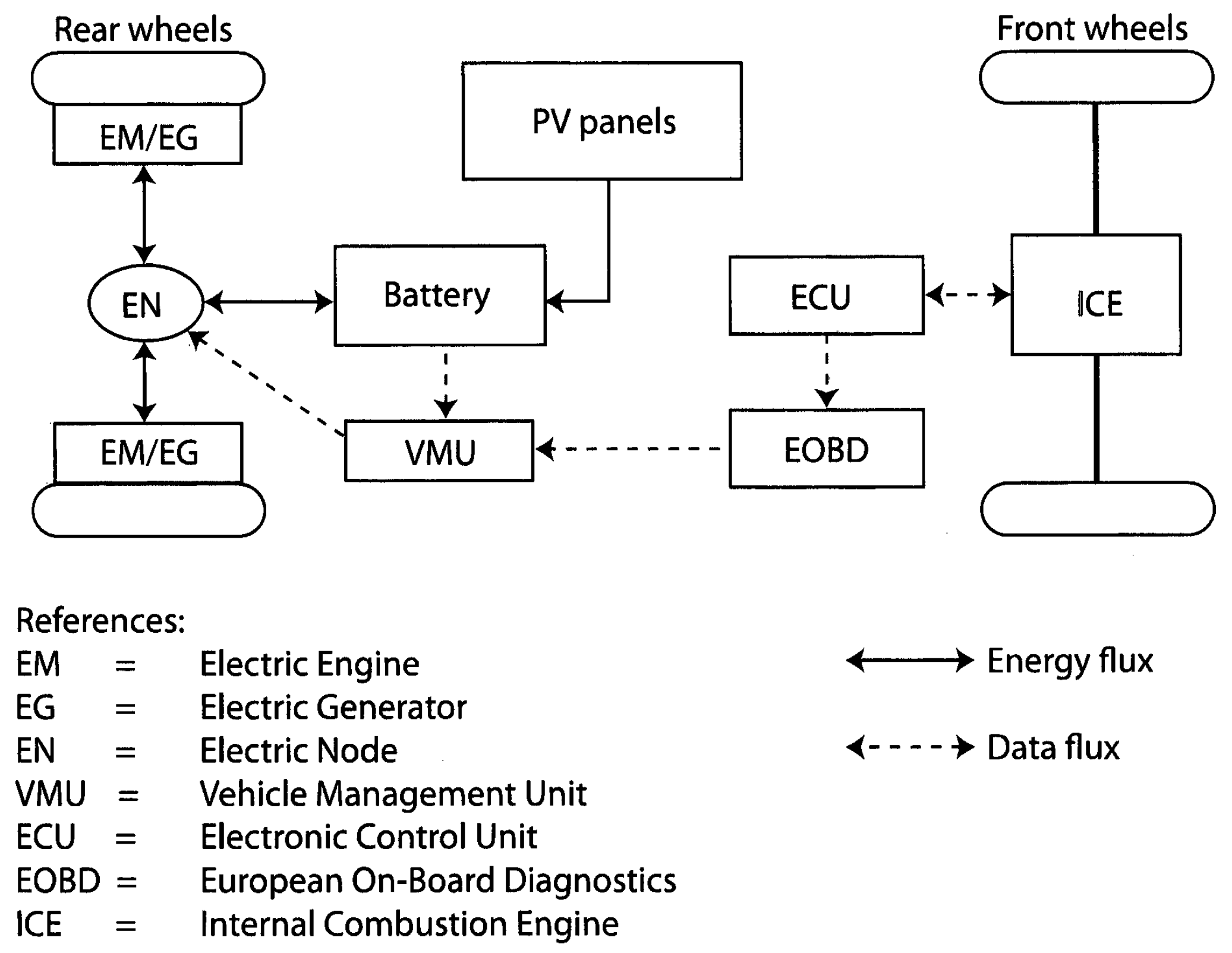
In order to simulate the fuzzy strategy in ADVISOR, Shaheb 2 (a parallel TTR HEV based on a KIA Pride) has been designed and manufactured at the University of Kashan [
18]. A simplified schematic of the Shaheb 2 architecture is shown in
Figure 7. Definition of optimum points to reduce the fuel consumption is the main objective. The application of this fuzzy control resulted in an average fuel converter efficiency of 29.43% on the UDDS driving cycle.
Table 4 indicates the vehicle and engine technical data of Shaheb 2.
In this paper, a multi-objective approach with two fuzzy controllers for torque and for state of charge (SOC) was adopted. In fuzzy torque controller, the normalized SOC is assumed as input, and engine torque as output. In SOC fuzzy controller, normalized SOC and its derivative are assumes as input, and additional torque as output: this term is then summed to the torque value provided by the first controller. The recourse to the SOC controller has also the purpose to determine a suitable battery depletion pattern. An adjustable gain allows matching the desired vehicle power. The membership functions for the two controllers make use of seven levels: positive big (PB), positive medium (PM), positive small (PS), zero (ZR), negative small (NS), negative medium (NM), and negative big (NB).
In Reference [
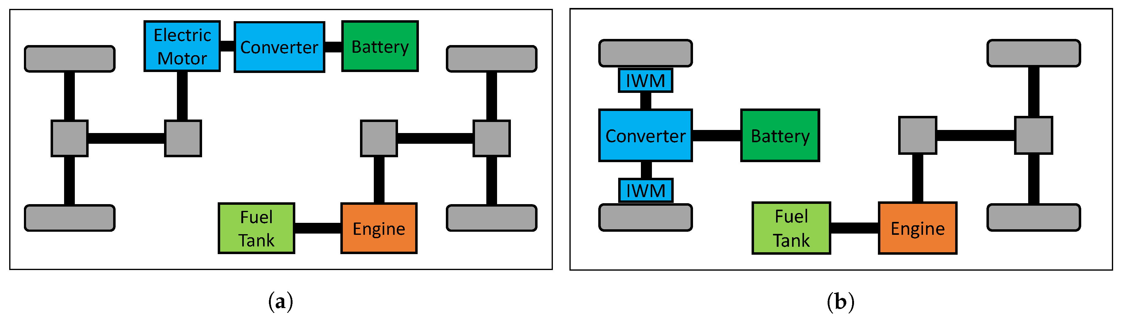
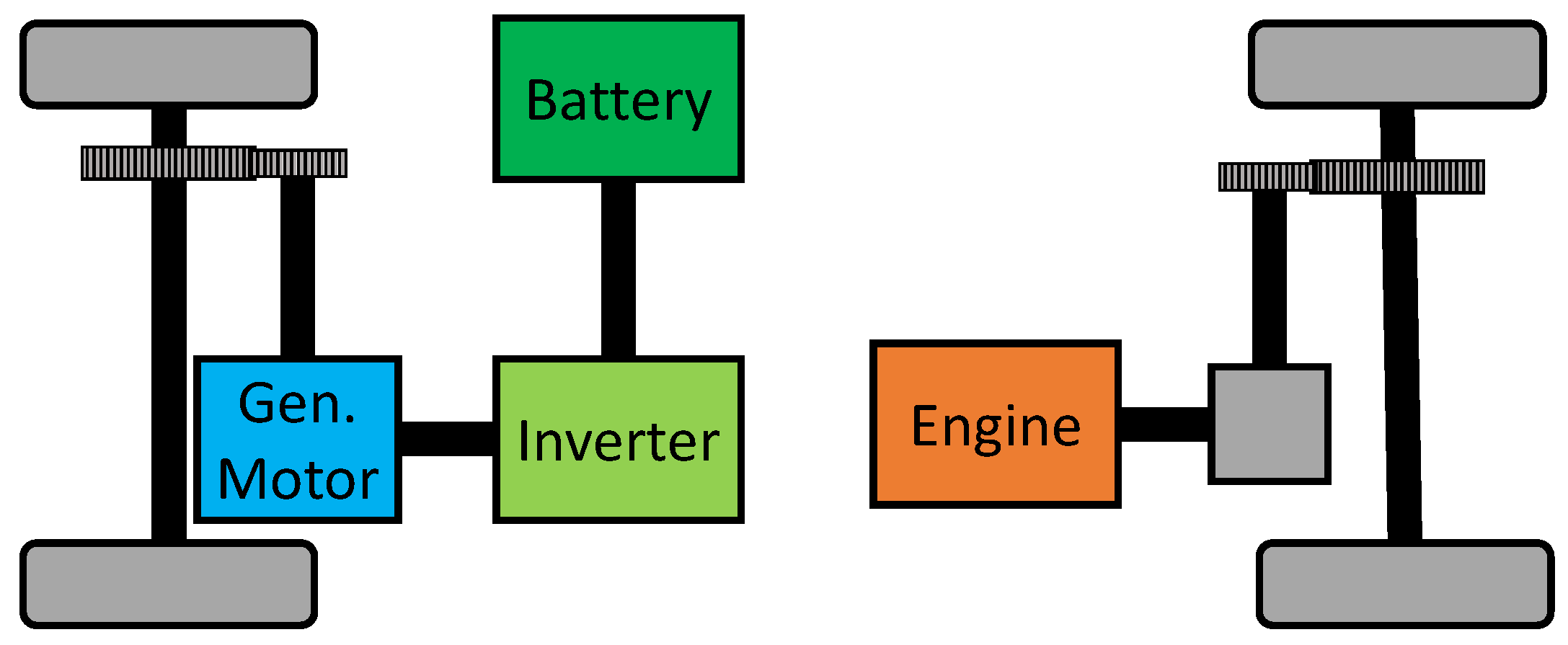
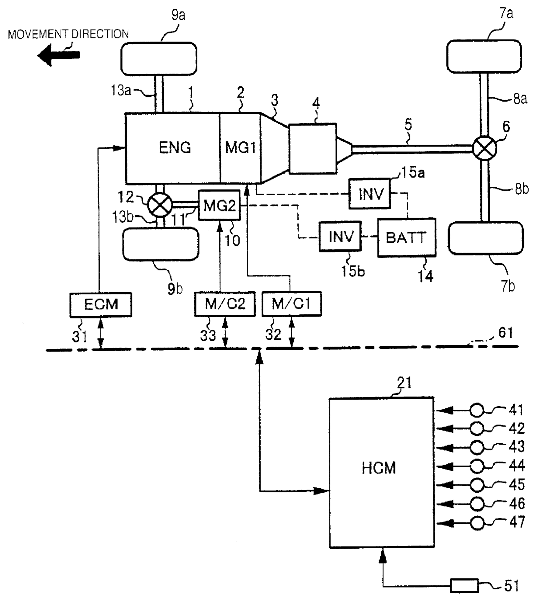
42] a fuzzy control system is applied as a main control block with a pair of membership functions to help the power flow controller to choose the adequate power diffusion by the hybrid drivetrain based on accessible resources in real time. In order to get the minimum fuel consumption for the desired trip, the Energy Management Strategy (EMS) operates in hybrid mode blended control strategy. The TTR equipped with in-wheel motors (IWM) in the rear wheels, with the same architecture depicted in
Figure 1b, was simulated in MATLAB as a Simulink model. The reference model which is used for comparison is a series–parallel HEV with rule-based EMS. The vehicle switches into hybrid mode when the needed power to the wheel oversteps the Power Threshold,
, line, it means that the level of
will be the determining multiplier for the mode selection of the EMS controller [
43]. The power flow in the TTR HEV is decided based on current vehicle speed and the Global Discharge Rate (GDR) value derived from the current State-Of-Charge (SOC) of the battery and remaining trip distance [
42]. Four different driving cycles are investigated and comparisons against other published models are equally encouraging, especially on high-average-speed drive cycles with up to 19.8% improvements in fuel consumption. Related results have been indicated in
Table 5 for different values of the GDR:
Very Very Low (VVL), 0%/km;
Very Low (VL), 1%/km;
Low (L), 2%/km;
Medium Low (ML), 3%/km;
Medium (M), 4%/km;
Medium High (MH), 5%/km;
High (H), 6%/km;
Very High (VH), 7%/km;
Very Very High (VVH), 8%/km.
Improvement thanks the proposed strategy are summarized in
Table 6. From the analysis of the text it is not clear or evident whether the same SOC variation in battery was recorded in the two cases.
The applied control strategy makes the proposed TTR HEV indicates undesirable performance on lower average speed cycle like the NEDC drive cycle despite higher average speed drive cycle such as the HWFET. Considering ICE size which is relatively bigger than conventional ones, the shortage in fuel consumption on NEDC driving cycle is undeniable since the bigger ICE leads to higher fuel consumption even though if it is idle.
The team that design the Shaheb 2 vehicle [
18] made a comparison between the fuzzy logic and the ON/OFF strategy for the control of the vehicle. Fuzzy logic approach resulted in a fuel economy 27% better than the one obtain with the use of the ON/OFF strategy.
Table 7 and
Table 8 report a summary of the comparison between ON/OFF and Fuzzy strategies on the UDDS cycle.
3.3.4. Torque Leveling Threshold Changing Strategy (TTS)
In Reference [
44,
45] the Torque Leveling Threshold Changing Strategy (TTS) is proposesed for a TTR HEV with IWMs architecture as depicted in
Figure 1b. This new fundamental concept of torque leveling is applied and compared with the Electric Assist Control Strategy (EACS) which one of the prevalent strategies for HEVs control and is based on the load following approach. The idea behind this mechanism is to run the ICE at a constant torque during the time the engine is running. Consequently, the efficiency of the engine can be guaranteed. The other advantage of the TTS is that it can adopt the threshold changing mechanism to operate the HEV in a charge-sustaining method.
In the TTS strategy, the powertrain works in net electric mode at low power demand, considering the fact that the low and medium power demands are identified by a battery charge and engine speed dependent threshold, the powertrain enters hybrid action with the ICE operating with a constant torque at medium power demands. So the ICE operates at its maximum power at higher loads or when the battery charge falls below a lower threshold. In other words, the vehicle is working in pure electric mode at low power demand, while for medium and high power demand the internal combustion engine is turned on and gives the required extra power.
The Ricardo Wave CFD engine simulator [
46] was used to obtain the engine map from experimentally validated simulations in order to investigate the fuel consumption. The one used in simulation is a 2 liters petrol engine with a peak power
of 120 kW and a peak torque
of 300 Nm.
Fuel consumption
and equivalent fuel consumption
achieved with the TTS application on four driving cycles WL-L (low speed), WL-M (medium speed), WL-H (high speed) and WL-E (extra-high speed) from the Worldwide harmonized Light vehicles Test Procedures (WLTP) and their deviation from results obtained with an optimal control strategy found via Dynamic Programming (DP) are shown
Table 9 [
45].
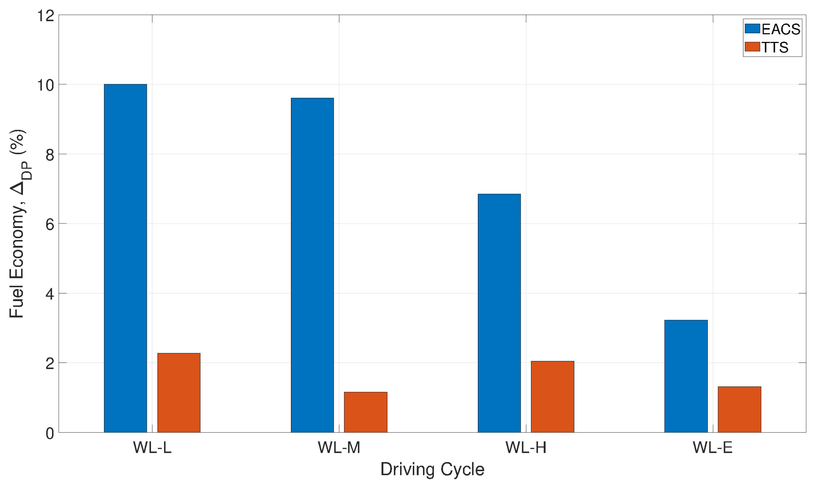
Analogously,
Figure 8 shows a comparison of EACS and TTS expressed as percentage difference compared to the optimal DP control. It can be noted that the EACS strategy does not show a satisfying result. On the same four driving cycles, the fuel economy obtained with the application of EACS is higher than the DP results by 6.02% on average (range 3.19%–10.08%). On the contrary, the TTS is able to achieve an impressive fuel economy, which is higher than the DP of only 1.14%–2.28% [
45].
Additionally TTS can be easily implemented for any kind of vehicle for which other control systems can not been easily implemented [
44].
Another advantage of TTS is that this strategy can be easily implemented for any kind of vehicle for which other control systems can not been easily implemented [
44]. Lastly, a Simple TTS (STTS), described with just two parameters, can perform similar performance to TTS while it is more convenient to implemented in practice [
44].
3.3.5. Deterministic Dynamic Programming
Dynamic Programming (DP) is a technique for solving a complicated problem by breaking it down into a collection of simpler sub-problems by means of the Bellman’s “principle of optimality” [
47]. DP method, according to the function to minimize (e.g., the fuel consumption of the vehicle), results in the identification of the optimal control strategy. In addition, DP allows to evaluate different layout designs of the vehicle in order to find the best results in terms of fuel consumption [
46]. On the other hand, the algorithm uses a backward strategy, starting from the final value of the driving cycle, which must be known a-priori. In addition, this method is time consuming, thus making DP not suitable for the real-time control, but rather for off line optimization, as a benchmark for real-time strategies, unless it is coupled with predictive models [
48].
In Reference [
49] the dynamic programming is proposed as a method to optimize the cost function combining the fuel consumption and the selected emission species for the hybrid vehicle. In Reference [
35] dynamic programming is applied in order to optimize the fuel economy and tracking safety for the adaptive cruise control. Besides, in Reference [
50] dynamic programming and the Pontryagin’s Minimum Principle (PMP) are compared for the energy management of HEVs. In Reference [
51] a cost function, such as minimizing a combination of fuel consumption and selected emission species over a driving cycle, with the control constraints for the vehicle mode is defined and dynamic programming has been adopted to calculate the vehicle dynamics.
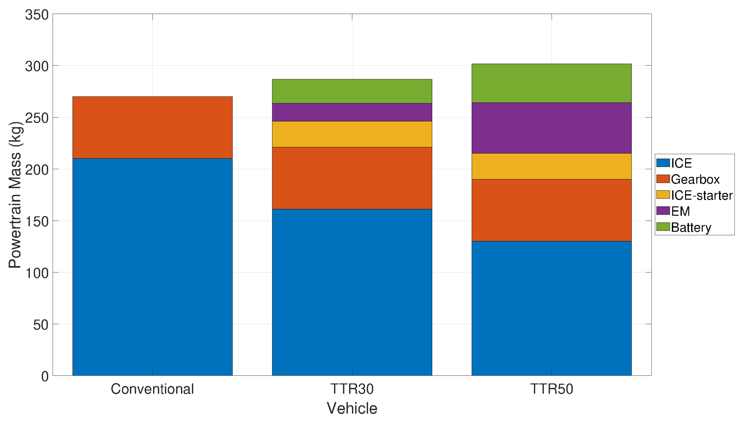
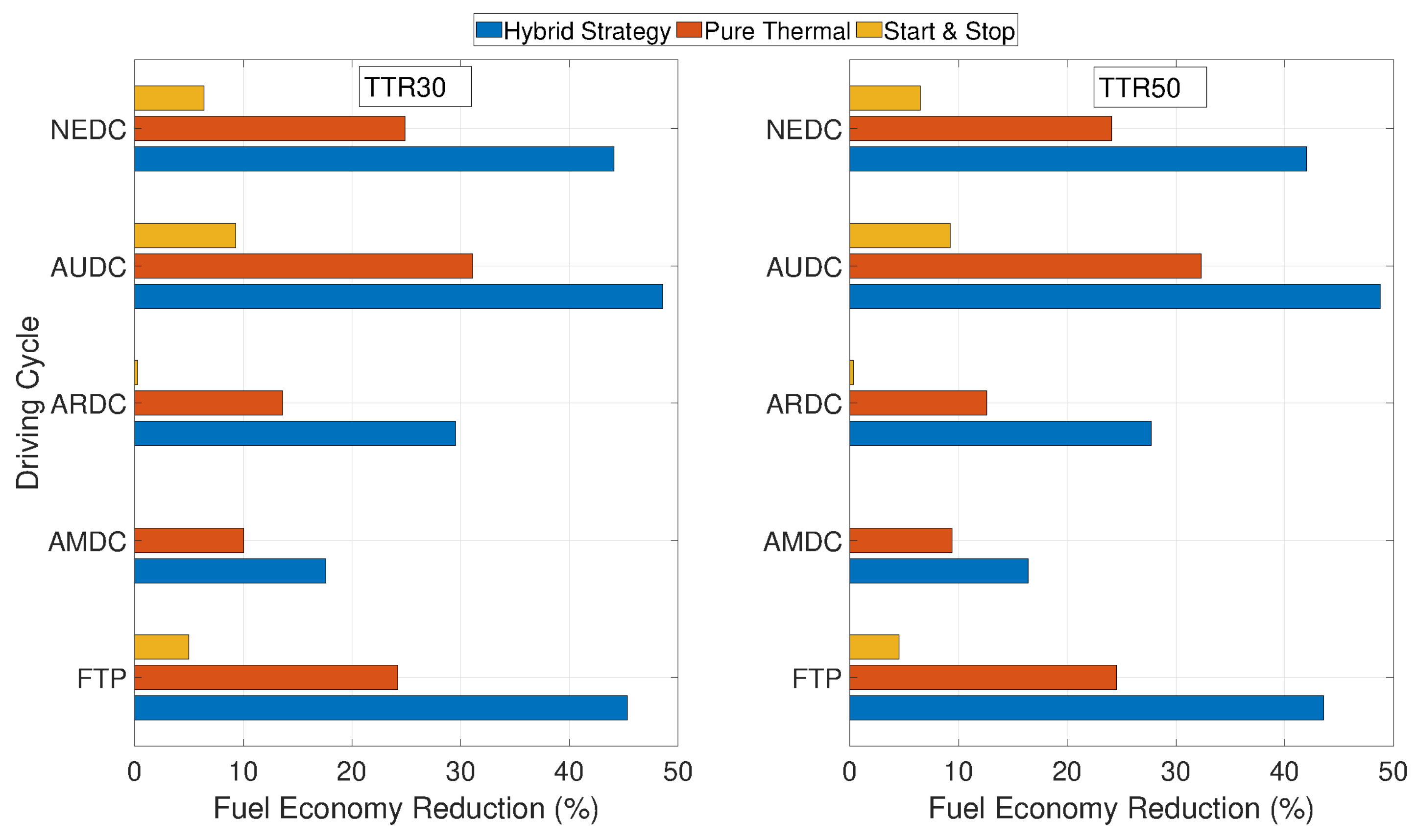
Considering the fact that DP strategy is time consuming, in Reference [
31] a mathematical technique to speed up the calculation time has been proposed. The base principle of this method is in creating a matrix which includes outputs of the vehicle model (i.e., ICE chemical power and battery electric power). Since this matrix is evaluated only once before evaluating the optimal control strategy, there is no need to calculate it for each step, thus values can be easily obtained from the matrix for a given combination of the control variables. The most strong point of this method lies in the interaction among the model and permutations of control and status variables saved in the DP grid. Through this method the computational demand in MATLAB software is reduced since configuration matrix saves all the information considering the vehicle in all probable scenarios, and it can be easily interfaced with the DP grid by means of simple matrix operations [
31]. This method proposed to lessen the computational time for all the optimizers resulted 15 times faster than DP-based ones. This approach has been applied to two types of TTR-already introduced in
Section 3.2—with different degrees of hybridization, TTR30 (30% hybridization) and TTR50 (50% hybridization). Results in terms of fuel economy reduction in respect to conventional vehicle are shown in
Figure 9.
3.3.6. Cyber-Physical Predictive Energy Management
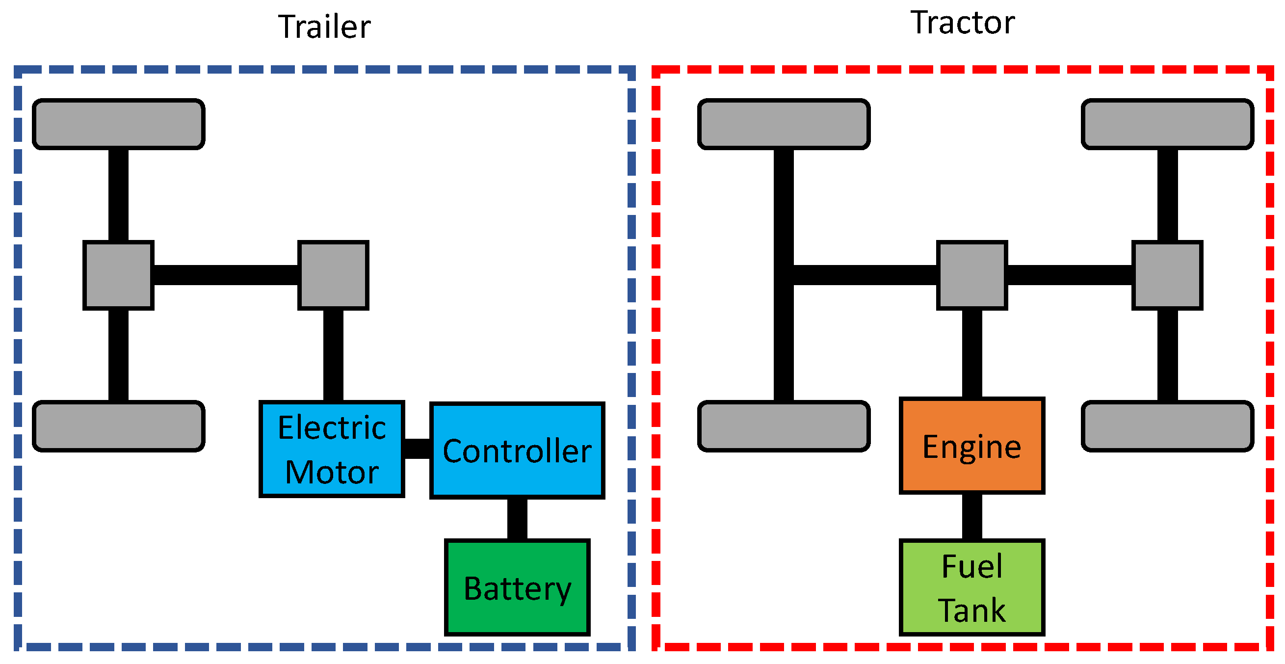
In Reference [
52], a Cyber-Physical System (CPS) with a previous knowledge of road elevation to achieve the optimum fuel consumption was proposed. In the first part of the work, a TTR powertrain applied to a truck, whose architecture is shown in
Figure 10, is proposed. In the second part, the proposed Average Power-based Model Predictive Controller (AP-MPC) is used for the energy management problem for this TTR hybrid vehicle with only road elevation known a-priori.
The characteristics of the main components for TTR hybrid vehicle are indicated in
Table 10.
The prescient MPC requires all the future driving data such as velocity and road elevation, thus making it not suitable for real-time applications. Instead, the AP-MPC strategy only needs the road elevation-that can be available from vehicle connectivity-making it suitable for real-time applications [
53].
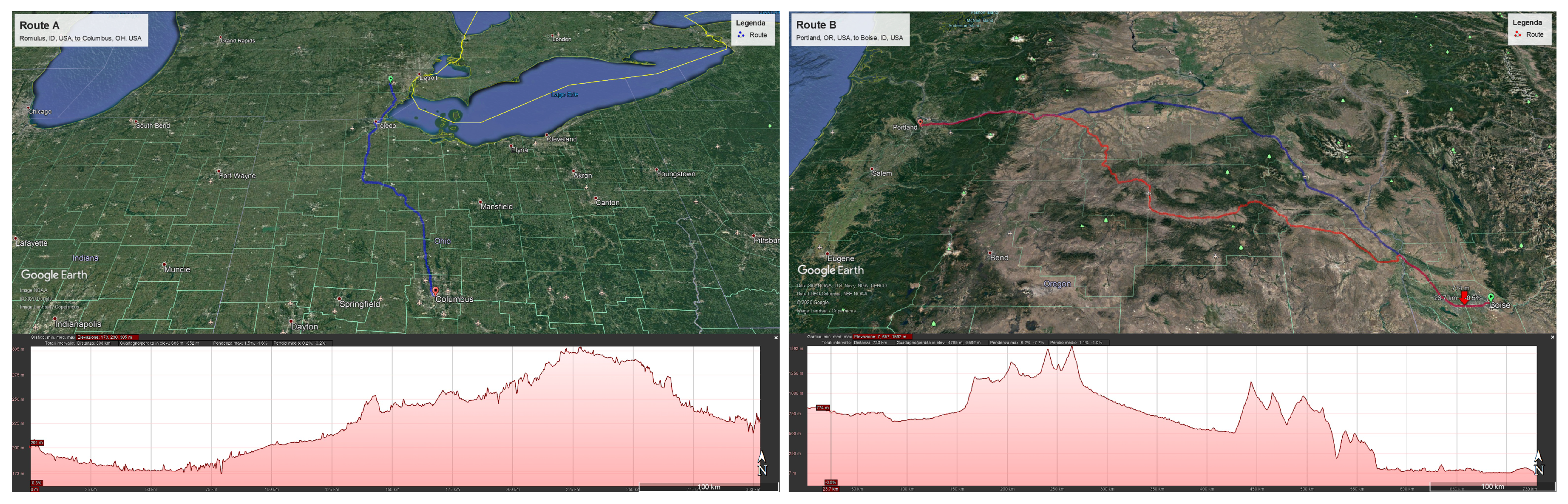
AP-MPC is also compared with rule-based EMS, or rather those strategies for hybrid vehicles control that require limited data as vehicle torque, the battery SOC, brake demands, operating conditions of the electric motor and combustion engine efficiency and local torque/speed constraints. Two different paths (A, B) are investigated and are presented in
Figure 11. Road elevation variations of path B are much larger than those of path A. This scenario is investigate to analyze the performance of AP-MPC in the mountain areas.
Performance achieved with the three different approaches are presented in
Table 11.
The Rule-based EMS on the path A results in 9.5% saving on fuel consumption compared to the conventional vehicle. The prescient MPC improves the fuel economy by 18.5% with all the driving data known a-priori. However, the AP-MPC, which can be applied in real-time, results in a 16.9% improvement in fuel economy, which it is not far from the prescient MPC. Likewise, even on the path B, the AP-MPC strategy shows performance similar with the prescient MPC despite using less data than it.
In the margins of the analysis of vehicle performance when a control based on a cyber-physical system is adopted, it is necessary to mention that these systems lend themselves to possible attacks from the outside [
54,
55]. Automotive cybersecurity is a topic widely covered in the literature. In fact, the communication protocol for vehicles (CAN-Controlled Area Network) was not designed, back in the 1980s, making safety considerations. Consequently, the use of control units and devices connected externally via Bluetooth or other networks makes the vehicle’s communication architecture vulnerable to external attacks, including DoS (Denial of Service), data extraction, code modification and interruption of functionality [
56,
57].
3.3.7. Sequential Linearization Control (SLC) methodology
In Reference [
58], a Sequential Linearization Control (SLC) strategy is proposed. This strategy is based on an algebraic mapping of the accelerator pedal signal, the battery SOC, and the vehicle normalized speed into a single torque command for the electric motor. The ICE control utilizes an altered accelerator pedal to throttle plate angle using a tunable gain parameter that, in turn, determines the sustained battery SOC.
The SCL algorith was implemented for two PHEV operational strategies and for a HEV operational strategy:
EVCD/HVCS: the vehicle starts in Electric Vehicle Charge Discharge (EVCD) mode with ICE turned off, depleting the battery down to a defined . When is reached, the ICE is turned on and the vehicle operates in Hybrid Vehicle Charge Sustain (EVCS) mode.
HVCD/HVCS: the vehicle starts in Hybrid Vehicle Charge Depleting (HVCD) mode, so with the ICE turned on, until is reached. At that level of charge, the operation mode turns into HVCS.
HEV-CS: this operational strategies applies to a non-plugin HEV. Thus, the vehicle operates in Charge Sustain (CS).
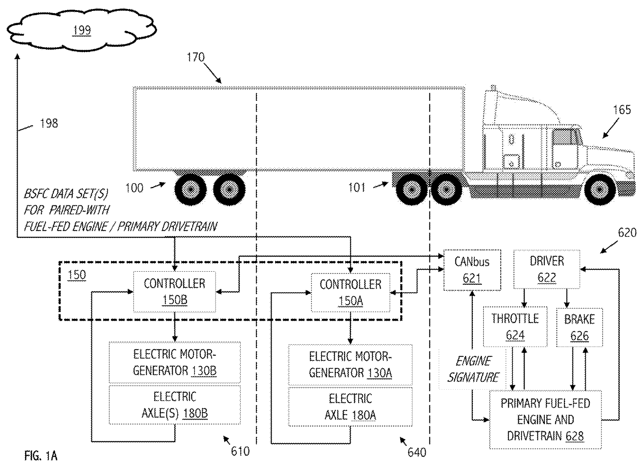
The proposed methodology was validated using data acquired from an actual hybridized Ford Explorer in a TTR powertrain configuration, with an architecture depicted in
Figure 1a. This vehicle was hybridized by a team of Georgia Institute of Technology students as an entry in three DOE/Ford FutureTruck university competition held between 2002 and 2004. The 3.0 liters V6 ICE drives the rear wheels of the vehicle through a five-speed automatic transmission, while front wheels are driven by a 150 kW AC-induction electric motor through a single fixed speed reducer. When the ICE is declutched from the rear differential, the vehicle drive in pure electric mode [
59].
The simulated performance using EVCD/HVCS and HVCD/HVCS strategies with a 40 kWh battery and their comparison with actual on-road Explorer under HEV-CS control are reported in
Table 12.
Fuel consumption and SOC values at the end of driving schedules for the EVCD/HVCS and HVCD/HVCS strategy for different battery sizes are compared in
Table 13.
3.3.8. Two-Degree-of-Freedom LPV Control Via Torque Vectoring
A strategy proposed for solving the torque vectoring problem, i.e., the independent control of each wheel, of a TTR HEV is the Linear Parameter Varying (LPV) presented in [
60]. In order to obtain high performance, especially under extreme driving situations, a two-Degrees-Of-Freedom (DOF) LPV self-scheduled controller is merged by using mixed sensitivity loop shaping. This strategy, which is based on a single Lyapunov function, can guarantee consistency and a level of control performance for all allowed trajectories.
This strategy has been implemented on a 14-DOF vehicle model for simulation. Among them, 6-DOF come from the center of gravity moving and rotating in all directions, 4-DOF are reserved for the suspension of the vehicle, and the other 4-DOF for the angular movement of the wheels.
The LPV controller is compared with a flatness-based controller where the generation of the force in longitudinal direction and the desired yaw momentum is demanded to a flat feedforward control in combination with a PID and a Linear Quadratic Gaussian (LQG) feedback control.
The proposed control was tested under severe driving situations and showed high and improved performance. It allowed to achieve good tracking and high robustness against disturbances and modeling errors.


