Review

An Extensive Review of Multilevel Inverters Based on Their Multifaceted Structural Configuration, Triggering Methods and Applications

by
Suvetha Poyyamani Sunddararaj
1,*,
Shriram Srinivasarangan Rangarajan
1,2,* and
Subashini N
1,*
1
School of Electrical and Electronics Engineering, SASTRA Deemed University, Thanjavur 613401, India
2
Department of Electrical and Computer Engineering, Clemson University, Clemson, SC 29634, USA
*
Authors to whom correspondence should be addressed.
Electronics 2020, 9(3), 433; https://doi.org/10.3390/electronics9030433
Submission received: 6 January 2020 / Revised: 12 February 2020 / Accepted: 28 February 2020 / Published: 5 March 2020
(This article belongs to the Special Issue Multilevel Converters)

Abstract

:
Power electronic converters are used to transform one form of energy to another. They are classified into four types depending upon the nature of the input and output voltages. The inverter is one among those types; it converts direct electrical current into alternating electrical current at desired frequency. Conventional types of inverters are capable of producing voltage at the output terminal that can only switch between two levels. The range of output voltage generated at the output is low when they are used for high power applications. To improve the voltage profile and efficiency of the overall system, multilevel inverters (MLIs) are introduced. In multilevel inverters the voltage at the output terminal is generated from several DC voltage levels fed at its input. The generated output is more appropriate to a sine wave and the dv/dt rating is also less leading to the reduction in EMI. Though they possess many advantages compared to the conventional inverters, the structural complexity and triggering techniques involved in designing multilevel inverters are high. Many studies are being carried out in defining new topologies of MLI with reduced switch as well as with the implementation of different PWM techniques. This paper will provide an extensive review on variety of MLI configurations based on the parameters such as the number of switches, switching techniques, symmetric, asymmetric, hybrid topologies, configurations based on applications, THD and power quality.

1. Introduction

The term MLI (multilevel inverter) was introduced in the late 20th century with the advent of a three-level converter. With the invention of multilevel inverters, the power rating of the device was increased owing to the number of levels and the device count was reduced when compared to conventional models. In recent times, the market for MLIs is becoming high in industrial sectors as well as in the fields where there is a need for high-power and high-voltage rating devices. Another interesting factor in the case of multilevel inverter is that it can be easily interfaced with renewable energy sources, plug in electric vehicles, batteries and capacitors [1]. Apart from this, the MLI delivers a high quality waveform with reduced harmonic distortion, capable of operating under fundamental and high frequencies, high power quality and better electromagnetic compatibility. The different classifications of multilevel inverters are as follows: the cascaded H-bridge multilevel inverter (CHB-MLI), the diode clamped multilevel inverter (DC-MLI) and the flying capacitor multilevel inverter (FC-MLI). The classification is shown in Figure 1.
In all the above-mentioned topologies, the quantity of electronic power switches required for designing the topology is high. The number of gate drives associated with these types is also high, which leads to a complex system. To reduce this complexity, several new topologies of MLI have been designed and tested by numerous researchers who are working in this field. The schematic of the newly derived topologies and techniques of MLI is shown in Figure 2.
This paper discusses the different types of new topologies in MLI-based on structural configuration and also their applications, their switching techniques, THD reduction and power quality issues. The paper is organized in such a way that the structural configurations are discussed at first, followed by the switching techniques, then some special topologies, and finally the power quality and harmonic issues associated with the multilevel inverter.

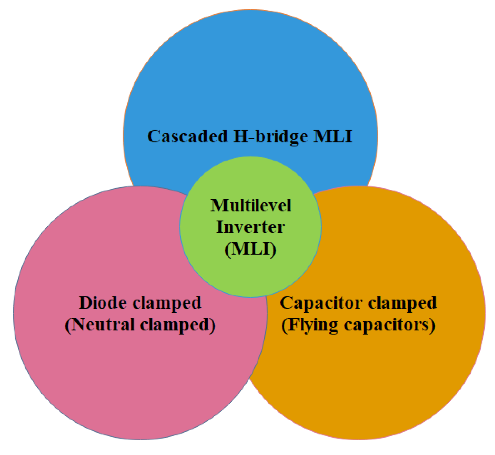
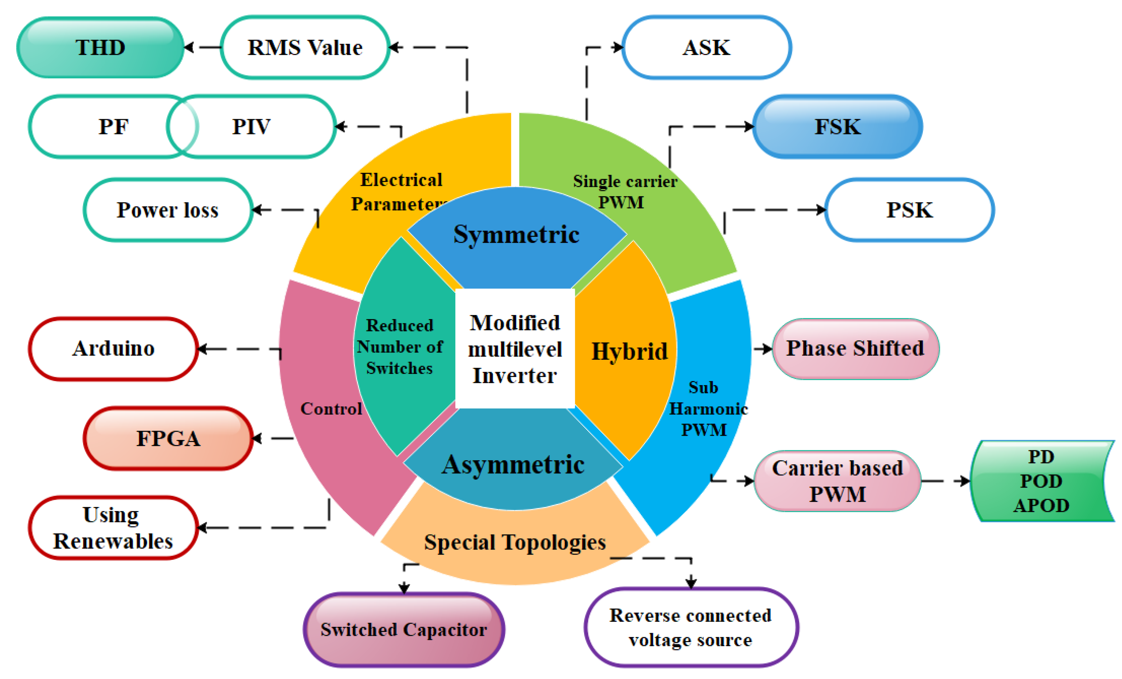
2. Structural Configuration of Multilevel Inverters

Based on the structural configuration MLI is classified into three types namely symmetric, asymmetric and Hybrid MLIs.

2.1. Symmetric Multilevel Inverter

Conventional multilevel inverters such as CHB-MLIs, DC-MLIs and FC-MLIs fall under the symmetrical category, since the magnitude of the DC voltage sources employed in the system are equal [2]. A new power circuit topology for an 11-level output was designed and it is given in Figure 3.
To increase the number of levels, two additional switches along with a DC voltage source was added to the existing configuration as given in [3]. But this configuration is different from the existing method due to the absence of a bidirectional switch in it. The desired voltage of the circuit configuration was derived from the following equation,
Nstep = 2n + 1
where n represents the number of dc voltage sources.
The maximum voltage at the output terminal (Vomax) of this n cascaded multilevel inverter is:
Vomax = n × Vdc
The voltage at the output end (Vo) can be increased by connecting the ‘N’ number of basic circuits. Though the inverter topology explained in [4] delivers a maximum voltage output, the number of switches is high. This leads to increased switching losses in the system. To suppress this shortcoming, a seven-level MLI with four DC sources was proposed by the authors in [5]. The symmetric configuration works in a fashion based on a pulse pattern, which is unique in nature to trigger the switches at the proper instant. The reduction in switch count results in low switching losses even though the sources are less utilized. Instead of using an H-bridge, this topology employs two switches for reversing the polarity. The seven-level, five-switch MLI is given in Figure 4.
The output voltage levels for the investigated topology can be calculated as follows:
p = (2 ∗ (S − 3))
where, p = number of output voltage levels,
S = number of switches
p = (2 ∗ Vdc − 1)
where, Vdc = number of dc sources
One of the main advantages of the symmetrical multilevel inverter is that it possesses very high modularity, which is absent in case of the asymmetrical MLI. Several research works are being carried out in the field of multilevel inverters, especially in symmetric and asymmetric configurations due their simplicity and efficiency compared to the conventional inverters. Such topologies are explained in a number of studies [6,7,8,9,10], where researches used a high number of power electronic semiconductor switches and gate drive circuits. Due to this, the circuit becomes complex and expensive. On account of this, a novel MLI with a reduced number of switching devices is suggested for producing a nine-level output. The circuit is shown in Figure 5.
The overview of the symmetrical configuration for M-level output is given as:
The required number of controlled switches is given by
(M + 5)/2
The number of driver circuits required
= (M + 5)/2
The total number of diodes is given by
(M + 1)
The number of DC sources required can be determined as
(M − 1)/2
Apart from this, the authors have also given a cascaded version of this nine-level topology [11], as shown in Figure 6.
The above configuration is designed in such a way that it has the ability to decrease the stress across the devices so that it can be employed in applications where there is a need for higher voltage. The H-bridge and the DC sources are switched with high switching frequency.

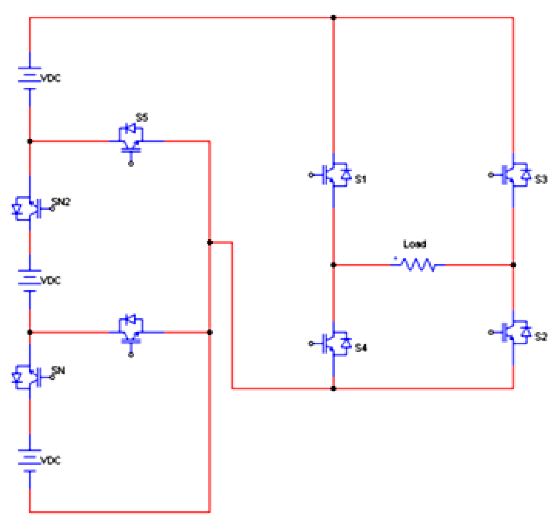
2.2. Asymmetric Multilevel Inverter

The only difference in the asymmetric multilevel inverter topology to that of symmetrical type is the rating of the DC input voltages and its control techniques. A cascaded H-bridge MLI with a lesser number of bridges is analyzed in [12]. This topology is capable of delivering maximum voltages at higher speeds even with minimum switching frequency. A seven-level asymmetric cascaded type inverter made up of two H-bridges for each phase is given in Figure 7. The DC source for the two H-bridges H1 and H2 is Vdc/2 and Vdc respectively.
In the above figure, it is clearly shown that the asymmetrical inverter uses only two bridges (with eight switches) for generating seven levels of output. The inverter is also subjected to different PWM Techniques and the THD is found to be low. Another asymmetric configuration is proposed by the authors in [13] with a high frequency link as shown in Figure 8.
The high frequency link employed in the system is used to supply the supplementary bridge, which is made up of a series-resonant converter along with a ferrite core (torroid core) transformer and diode rectifiers. The transformer used in this topology is to provide galvanic isolation between the bridges. The operation of MLI is based on a control mechanism called nearest level control (NLC). The controller will match a voltage signal close to the reference signal value. The power delivered in this system is inversely proportional to the frequency.
The controller is operated in such a way that the output voltage has to be varied whenever the source voltage is changed. This results in maintaining the voltage levels of the DC–AC converter and the total harmonic distortion.
One more cascaded H-bridge MLI is suggested by the researchers in [14] for a seven-level output. From the Figure 9, it is clearly understood that the number of switching devices gets reduced in this topology when compared to the conventional cascaded multilevel inverter configuration.
For the same seven-level output, a new MLI topology with switched capacitor (SC) technique is proposed and the circuit is given in Figure 10. It consists of a chopper and H-bridge inverter at the front and back, respectively.
A combination of switches is turned ON for producing a positive voltage and negative voltages [15].
The asymmetric topology is also capable of producing higher levels of voltage, as explained by the authors in [16]. The authors analyzed a 21-level MLI made up of a full bridge converter with semiconductor switches and different voltage sources. A set of switches was used to obtain the different levels of voltage. The circuit configuration is shown in Figure 11.

2.3. Hybrid Multilevel Inverter

The hybrid multilevel inverter is an amalgamation of symmetric and asymmetric inverter topologies. A novel hybrid MLI for drive applications was proposed in [17]. In this paper, the authors discussed a three-phase inverter in which each leg of inverter delivers two outputs for each single phase inverter and induction motor. This is capable of operating as three single-phase MLIs. The voltage levels are obtained by matching the capacitor voltages with that of Vdc. The circuit is given in Figure 12.
A similar topology was investigated by the researchers for a three-phase application [18,19]. In this topology, each leg is meant for a single phase and it was designed with an H-bridge in series with a DC voltage source. The circuit diagram for both the topologies is shown in Figure 13 and Figure 14 respectively.
An hybrid MLI based on switched capacitor technique is given in Figure 15. Here, a basic unit along with an H-bridge configuration is proposed for developing the positive, negative and zero voltages respectively. The magnitude of the voltage generated is given by
Vk = (5)V1
Due to the implementation of different voltage sources, it is 80 percent asymmetric in nature [20].
To overcome the drawbacks of utilizing more switches even for low-level inverters, a new hybrid cell technology was proposed by the authors in [21]. The high level of voltage was achieved with the arrangement of multilevel VSIs (voltage source inverters). The number of DC voltage sources and switches required for the implementation of the topology are selected based on the following expression:
M = (P + 5)/2
Vndc = (P − 1)/2
where P is the number of levels, M is the number of switches and Vndc is the number of DC voltage sources. The circuit topology is as follows in Figure 16.
A neutral-point clamp with floating capacitors capable of producing multilevel voltages is investigated in [22,23] and filed for patent (Efficiency and Dense Architecture: EDA5). The circuit configuration of the mentioned topology is shown in Figure 17.

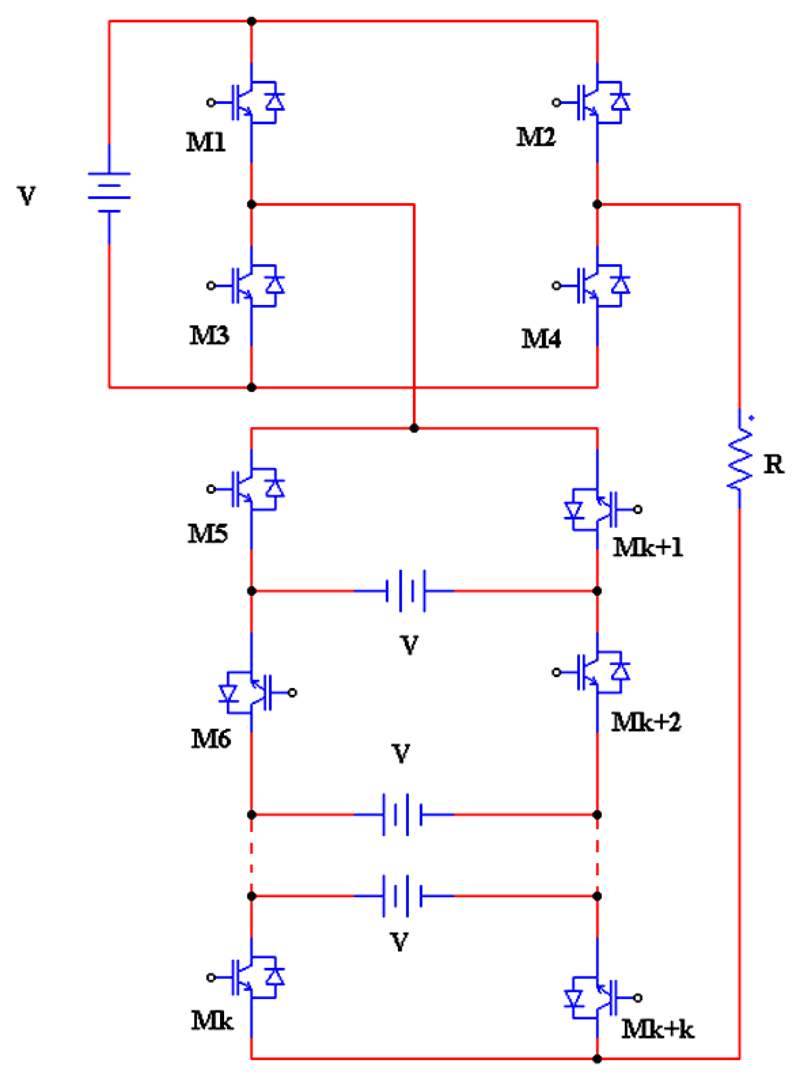
3. Reduced number of Switches

Some of the modified MLIs with minimum number of switches have also been discussed here in this literature. A new idea was proposed by the authors of [24] for producing very high levels of stepped voltage. This can act as a replacement for the conventional cascaded MLI with numerous switch counts. The suggested topology was tested for both symmetric and asymmetric configuration for a switch count of six, as shown in Figure 18.
A seven-level inverter made up of six power semiconductor devices is investigated by the authors of [25]. Both the performance and output rating of the inverter is maintained even though the switch count was reduced. The topology comprises of three DC voltage sources at the supply side and a full bridge circuit. It is a modification of the work implemented in [26], in which nine switches were used for obtaining a seven-level output. The circuit is given in Figure 19.
Apart from normal techniques, this paper has implemented a novel technique for MLI by combining the process of level generation and polarity generation. The general configuration consists of n-number of DC sources for generating 3n levels of voltage at the output. The topology can be extended to higher levels of voltage by adding additional DC sources with the basic unit. The circuit for a nine-level inverter based on the above technique is shown in Figure 20.
The number of switches required for the inverter for a specific value of voltage can be determined using the following formula.
Number of switches:
(NS) = 4m + 1
where m is the number of DC sources [27].
Like the above-mentioned topology, another new technique has been discussed in [28] to eliminate the voltage imbalance and also to protect the false conduction. This is done by designing an MLI without any capacitors and diodes. The circuit topology given in Figure 21 proved to be the best in terms of switching losses and THD.
The switching losses can also be reduced by implementing a circuit configuration like that shown in [29]. It consists of nine switches and two DC voltage sources for generating a voltage signal at nine levels. Though the switch count is high when compared to the previous topologies, it is lesser in count than that of a conventional inverter for the same level of voltage. The circuit is given in Figure 22.
A symmetrical inverter with reduced switch count is implemented in [30]. This can be extended for higher voltage levels by adding the required number of voltages and switches.
The formula for calculating the number of switches is defined as follows:
NS = m + 3
NL = 2NS − 5
where m is the number of DC sources in the symmetrical MLI.
The maximum value of voltage at the output end can be expressed as
Vo = nVdc
The basic unit and the same topology for nine-level output voltage are given in Figure 23 and Figure 24 respectively.
Previously we have seen many topologies with reduced switch count and DC sources. In all the cases, as the number of level increases the switches and sources gets increased. This may lead to circuit complexity. To overcome this drawback, a novel design was implemented in [31], which generated the same number of voltage levels per phase with the help of only two batteries and eight switches. In this newly defined circuit, the number of devices and batteries reduced as the levels increased. The schematic is shown in Figure 25.
Similar to a neutral point clamp inverter discussed in the asymmetric section of this literature, a hybrid model combining a three-level NPC connected in series with a three-level H-bridge cells [32]. The general configuration of this topology is given in Figure 26. The bus voltage ratio is used to increase the voltage levels and also to optimize the switching losses of the device. The power distribution among the cells is improved with the hybridization technique. It also results in reduced switch count.
Many research works have also been carried out in this area as discussed in [33,34]. The structure for both the topologies is shown in Figure 27 and Figure 28 respectively.
One more configuration based on bidirectional and unidirectional switches is explained by the authors of [35,36]. In this paper, the authors used the CE (common emitter) configuration. The unidirectional switches comprised one power device and one reverse diode which blocked the voltage in one polarity and makes the current flow through both paths. The same concept was applied for bidirectional switch configuration as well. The circuit configurations are shown in Figure 29 and Figure 30 respectively.
With the same concept, another paper proposed a structure based on the asymmetric structure which combined a reduced switch MLI and a cascaded MLI. The different levels of voltages were generated with a combination of unidirectional and bidirectional switches. The generated voltage had different paths since the sources were connected in different directions and it served as the major benefit of this topology [37]. The circuit topology is shown in Figure 31.
An overview of all the topologies discussed is given in the Table 1.

3.1. Multilevel Smart Inverter

A multilevel inverter (MLI) can act as a smart inverter by making some changes in the control system of the inverter topology. A modified hybrid multilevel inverter with less switches was proposed in [38]. In order to make the inverter a smart device, IoT was employed for its control. Initially, the parameters of the inverter were scrutinized with the help of IoT widgets and settling measures. The parameters that are not comparable (inactivity of packages) were combined together and separated from the IoT gadget and the rest of the parameters were given to the goal gadget. This helped to find the change probabilities for the associations. The overall system is given in Figure 32.
A novel MLI configuration was analyzed in [39,40,41]. It delivers a nine-step output voltage with high voltage gain. It consisted of a developed switched capacitor circuit (DSCC) at the source terminal of the inverter and another circuit was a conventional H-bridge circuit. The H-bridge circuit connected at the end terminal of the inverter produced the negative sequence of voltage levels at the output. The circuit of multilevel inverter is given in Figure 33.
To maintain a high voltage profile, an intelligent control technique can be used to control the operations of the multilevel inverter. Another topology of MLI was discussed in [42]. In this paper, the authors have implemented a circuit by integrating a full bridge inverter and combination of switched DC sources [43]. The generalized circuit diagram of the above-mentioned hybrid MLI is shown in Figure 34.
This hybrid configuration can be extended to high number of output voltage levels by adding corresponding switches and DC sources. The SDCS design operates in asymmetric manner in order to increase the voltage level at output side.

3.2. PWM Techniques for MLI

Numerous research works are being carried out on multilevel inverters by several researchers in the field of power electronics. In order to switch these inverters, various modulation techniques are used. Among all those types, carrier based and space vector modulation techniques are most commonly used.
For a multilevel inverter, the modulation techniques such as single-carrier sinusoidal pulse width modulation (SCSPWM) and subharmonic PWM (SHPWM) can be used. Between the two categories, subharmonic PWM is an exclusive control strategy for multilevel inverters. The further classifications of SHPWM techniques are the phase-shifted carrier PWM method (PSPWM) and the carrier disposition PWM methods.
In the carrier disposition method, the multicarrier waveforms are obtained with the implementation of any one of techniques discussed below:
  • phase disposition (PD);
  • phase opposition disposition (POD);
  • Alternative Phase Opposition Disposition (APOD).
For instance, an m-level MLI using a level-shifted multicarrier modulation scheme requires (m – 1) triangular carriers, all having the same frequency and amplitude [44,45].

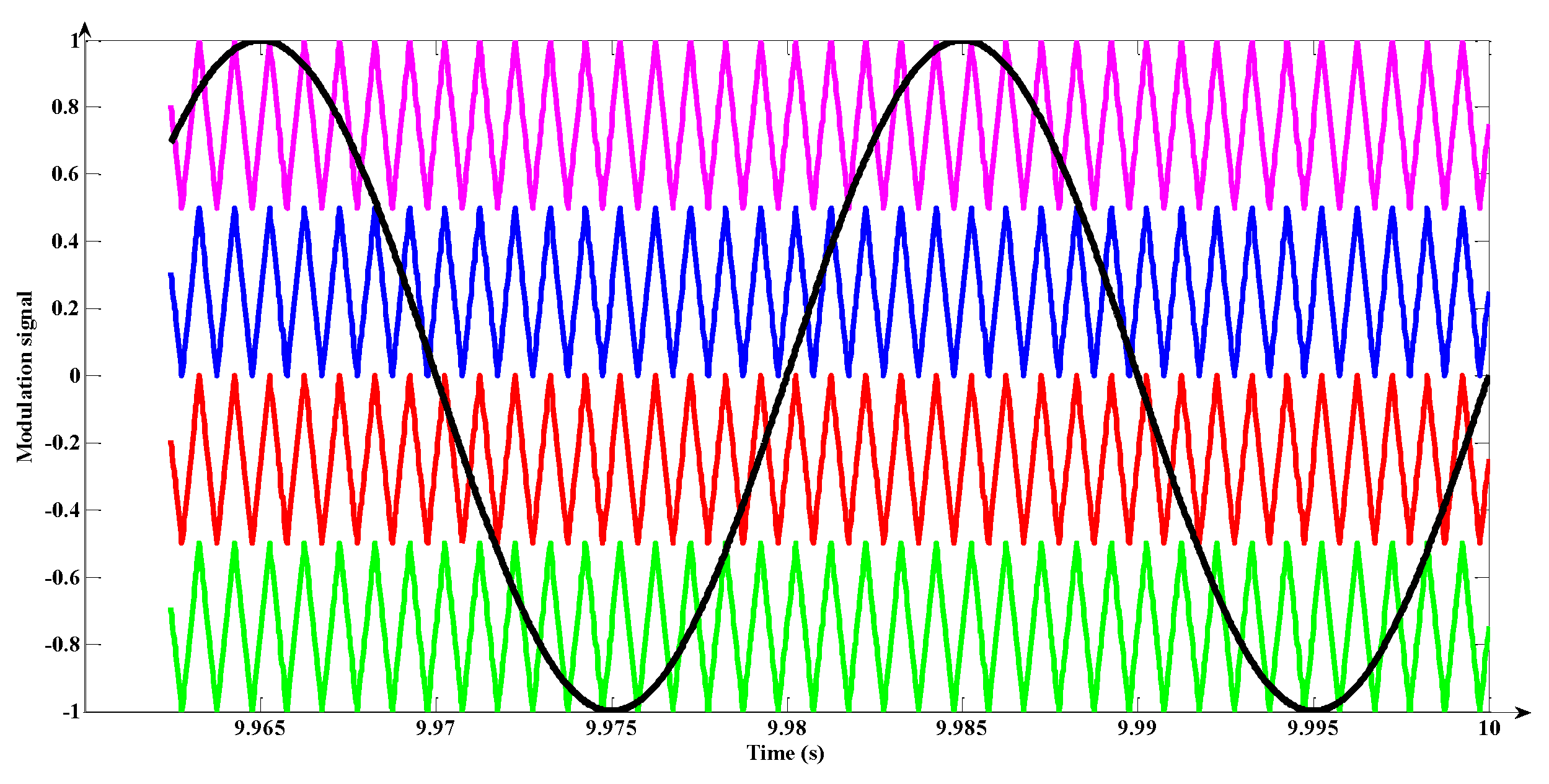
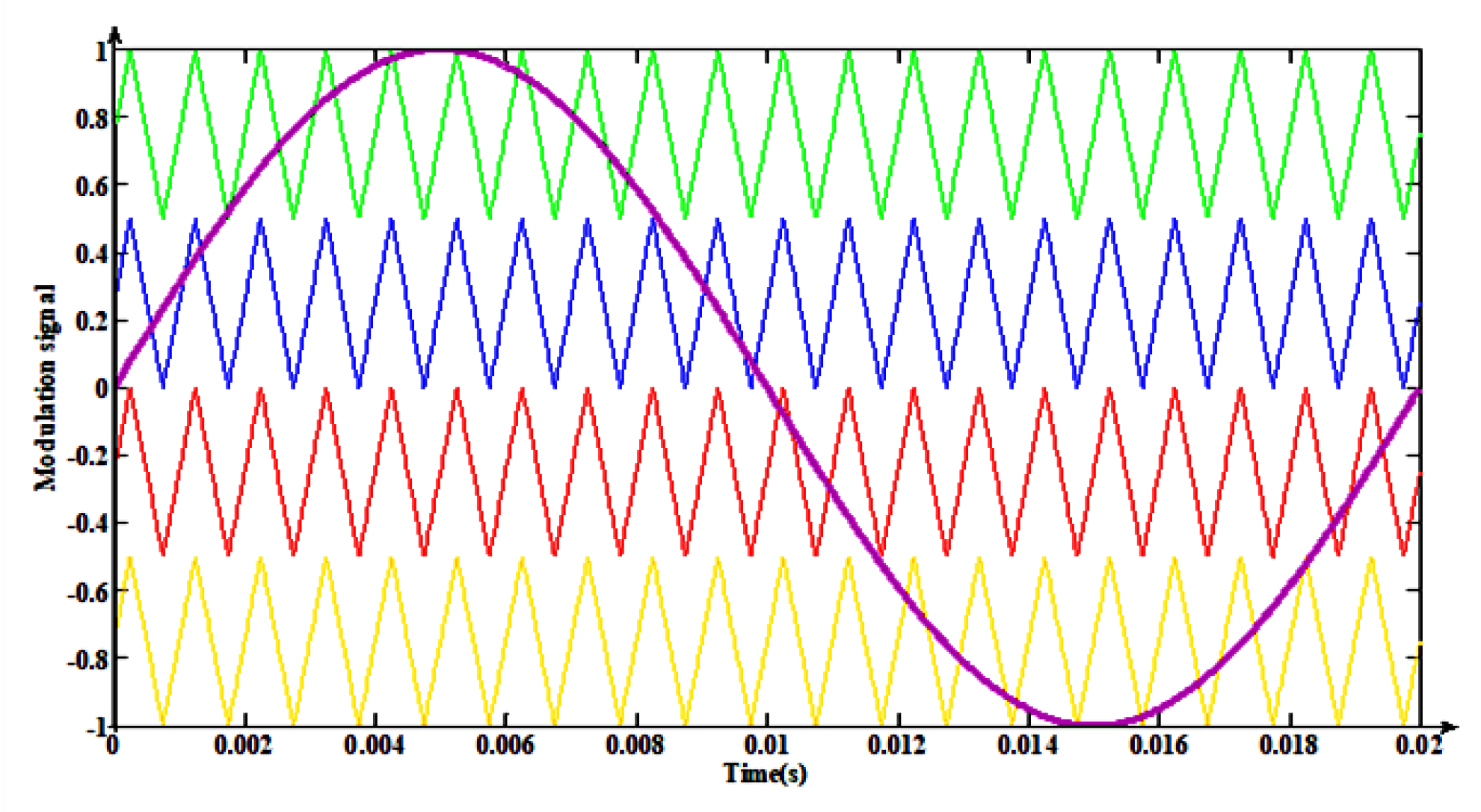
3.3. Phase Disposition Method

In the phase disposition (PD) method, all carriers are selected within the same phase. With reference to the related research works in this field, this method results in low THD at higher modulation indices than the other schemes [46]. The simulated waveform in the MATLAB/Simulink software for carrier waves and reference signals is shown in Figure 35.

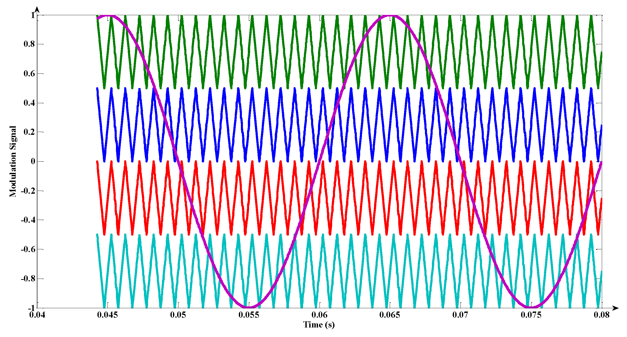
3.4. Phase Opposition Disposition

In this method, there is no harmonic at the carrier frequency and its multiples and the diffusion of harmonics occurs in that region [47]. The simulation of the POD technique was carried out in MATLAB/Simulink environment and waveform is shown in Figure 36.

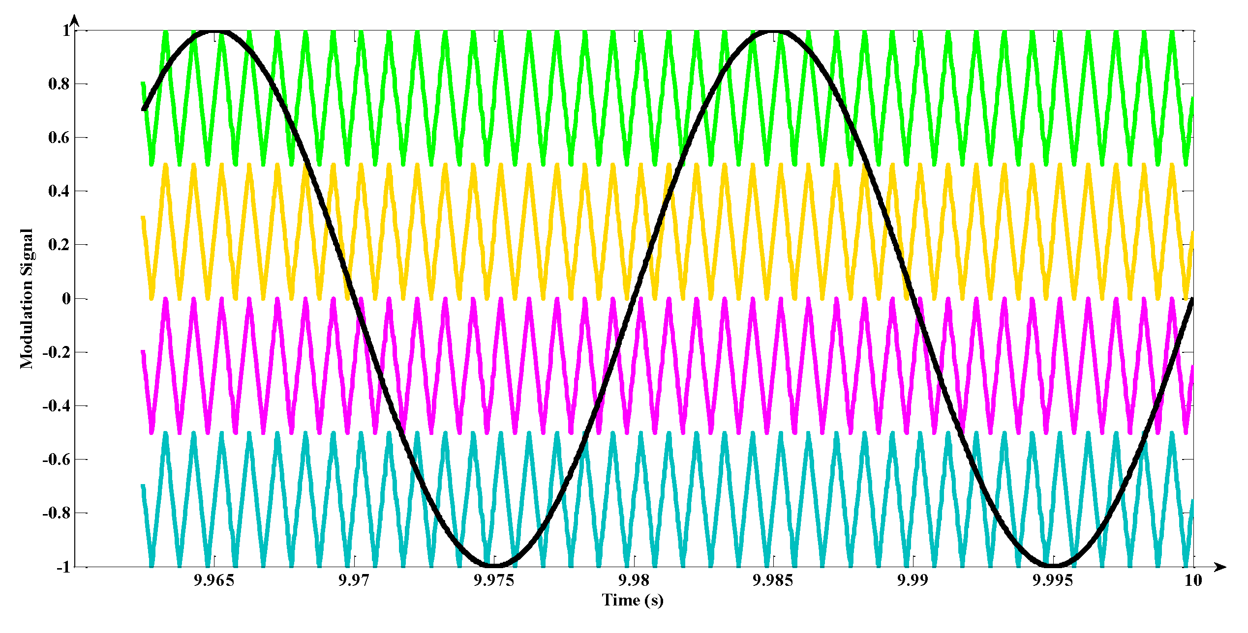
3.5. Alternate Phase Opposition Disposition

In this method, each carrier signal is shifted by 180 degrees in phase from the other signal. This method gives almost the same results as the POD method but the only difference is that the triple-n harmonics are eliminated due to the cancellation of line voltages [48,49]. The simulation of the APOD technique was carried out in MATLAB/Simulink environment and waveform is given in Figure 37.

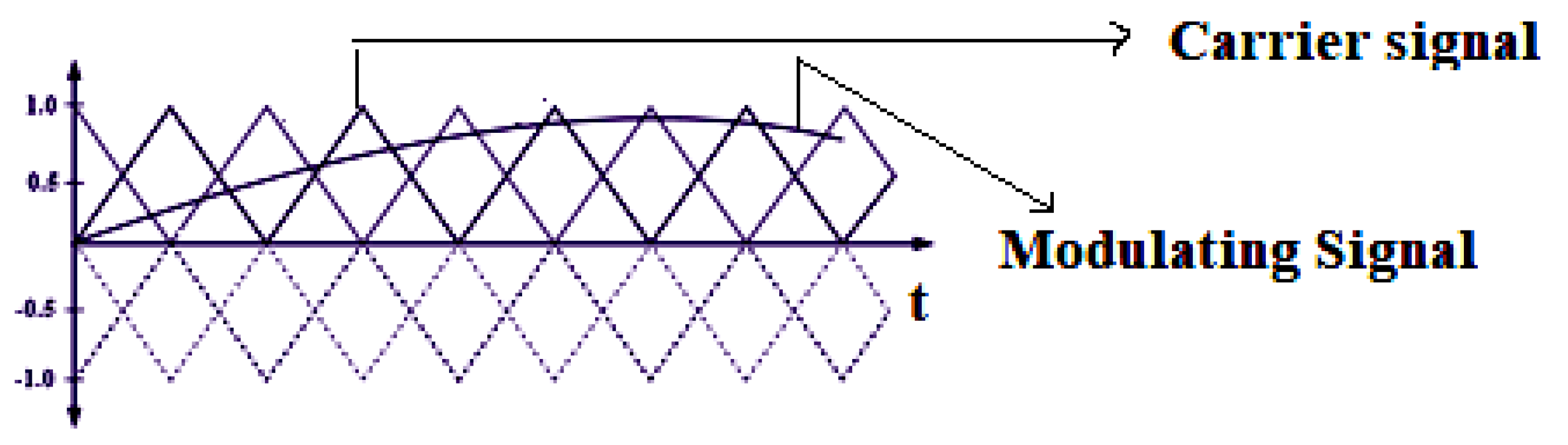
3.6. Multilevel Carrier PWM Technique

The conventional multilevel carrier PWM is capable of comparing several carrier wave signals with a single reference signal per phase. For a p-level inverter, p-1 carriers with the same frequency and amplitude are used. The authors have explained a novel PWM technique in which the carrier signals are disposed alternatively [50]. The waveforms for both conventional and modified multilevel PWM signals are shown in Figure 38 and Figure 39 respectively.
A hybrid-PWM technique was discussed in [51] using multiple carriers. This technique is a hybrid between the carrier-disposition PWM and the phase-shifted PWM. The carriers are shifted both vertically and in phase in order to produce a pulse [52]. Thus, it includes the features of both the techniques. The waveform is shown in Figure 40.
Another hybrid modulation technique is investigated in [53]. The authors have explained a PWM technique with the hybridization of the fundamental frequency modulation (FPWM) and multiple sinusoidal modulations (MSPWM) techniques. The generated wave has reduced switching loss as in the case of FPWM and also delivers as good harmonic characteristics as that of a MSPWM method. This hybrid modulation scheme is integrated with sequential switching and simple base PWM circulation scheme in order to balance the power dissipation among the power modules.

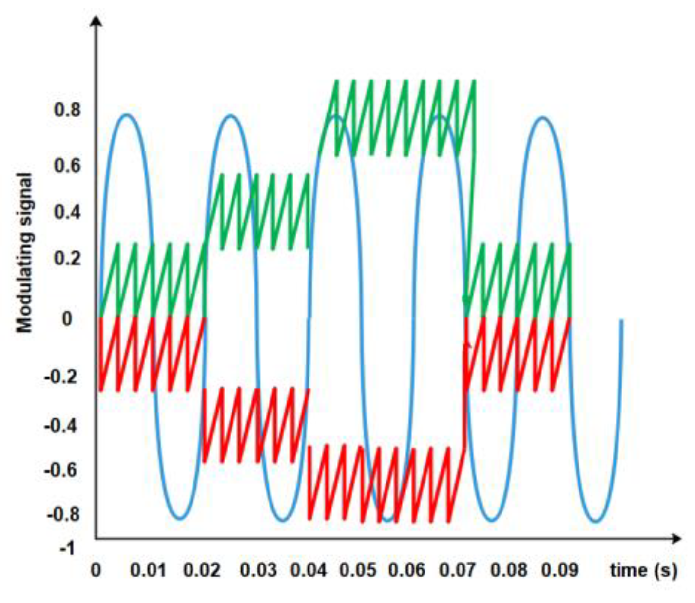
3.7. Depenbrock’s Discontinuous PWM Technique (DPWM)

This is a discontinuous PWM technique in which a zero-sequence signal is injected to a sine wave [54,55]. This kind of signal is termed as Depenbrock’s discontinuous PWM technique. The waveform for single-phase and three-phase Depenbrock’s PWM is shown in Figure 41 and Figure 42 respectively.

3.8. Selective Harmonic Elimination (SHE)

The purpose of the SHE-PWM technique is to get rid of certain lower order harmonics [56,57,58,59]. Other than triple-n harmonics (since they are getting eliminated naturally in three-phase applications), the remaining order of harmonics can be removed by means of proper filter. But the drawback in SHE is that it cannot obtain solutions for non-linear equations easily. Therefore, certain optimization techniques have to be implemented. The model waveform for the SHE method is shown in Figure 43.

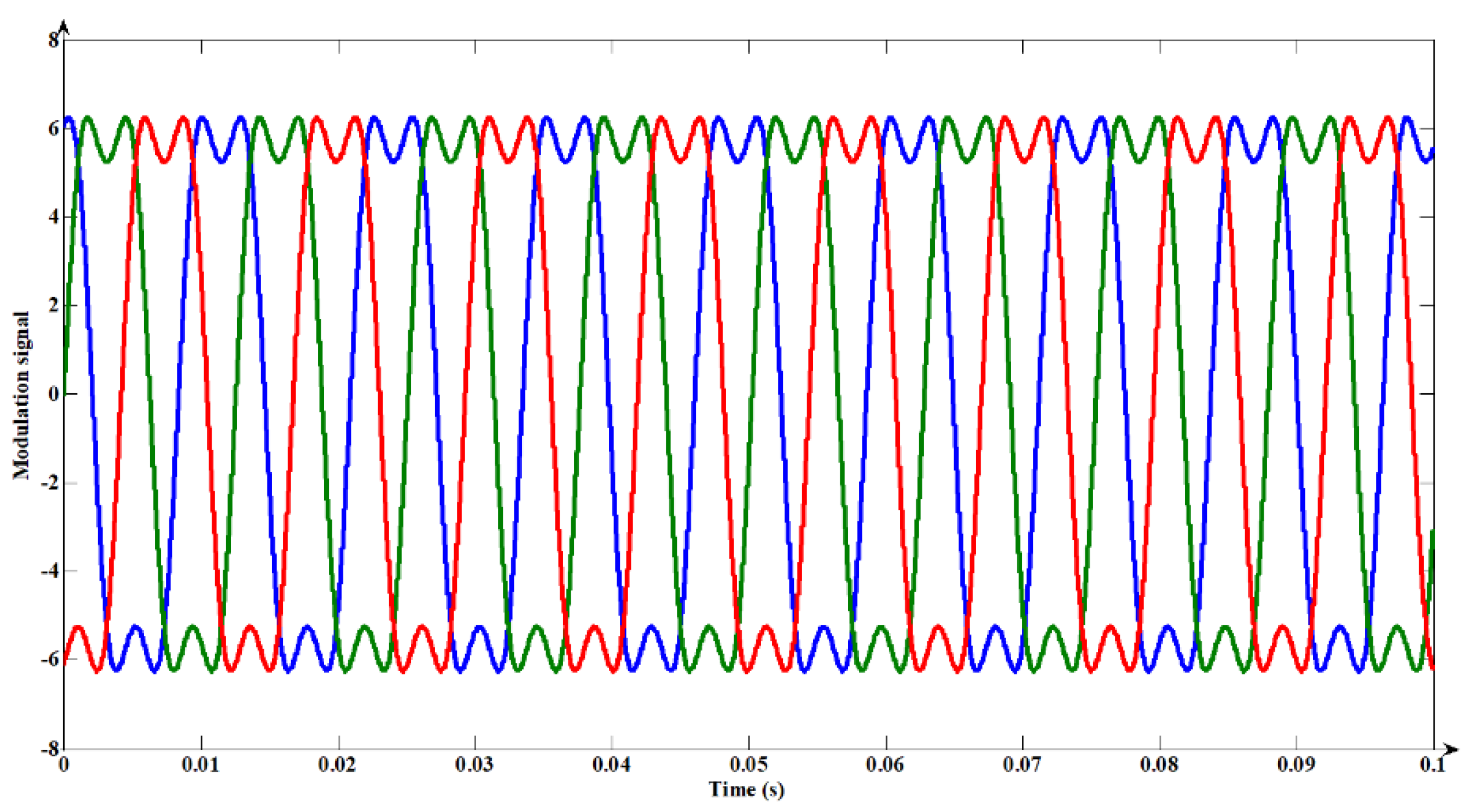
3.9. Space Vector PWM Technique

In the space vector modulation technique, the reference vector is approximated by switching among the nearest voltage space vectors [60,61,62,63,64,65]. The steps involved in the implementation of SVPWM are [66,67,68].
  • Identification of each sector;
  • Proper switching of voltage space vectors has to be determined;
  • The duration of each voltage space vectors in the switching sequence should be identified;
  • Determination of an optimum switching sequence.
To determine the operating sector a fractal-based technique was discussed by the authors in [69]. A fractal scheme based on a 60-degree-coordinate SVPWM was implemented in order to reduce the computational complexity. A multilevel inverter (five-level) in a 60° coordinate system is shown in Figure 44.
A similar topology was discussed in [70] where the same two coordinate systems were implemented. The vector diagram for the 60-degree SVPWM of this topology is shown in Figure 45.
Several other SVPWM topologies were discussed [71,72,73,74,75,76,77] by the researchers for three-level inverters and higher levels.

3.10. FPGA Based Modulation Technique

A novel technique based on FPGA control was proposed in [78]. It proved to the best in improving the modulation index range and also the power quality. The control block for PWM generation using FPGA is shown in Figure 46.

3.11. Area Integration PWM Technique

This is a newer scheme explained by the authors in [79] for the generation of PWM pulses. It involves evolutionary programming (EP) for optimizing the pulse width [79]. The basic idea behind this technique is the integration of total area of the pulses with a sine region. Thus, it is named the area integration PWM (AIPWM) technique. The basic idea for a seven-level output with six pulses per half cycle using this AIPWM method is shown in Figure 47.

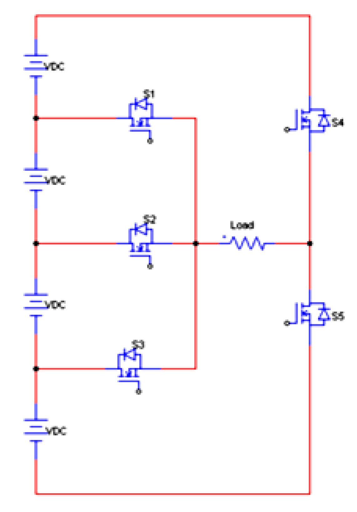
4. Special Topologies of MLI

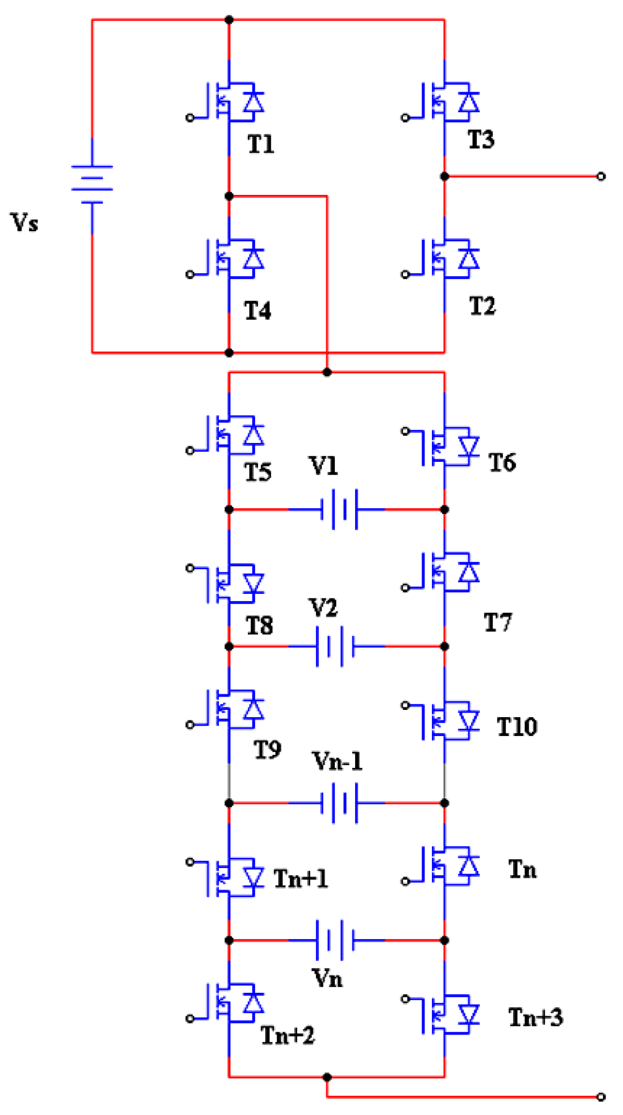
4.1. Switched DC Source MLI

A new topology of MLI with alternate DC sources linked on the opposite polarities was designed by the authors in [80]. This kind of arrangement reduces the number of power semiconductors, which are responsible for generating multilevel output. This topology can be used in medium-voltage drive applications in order to provide isolated DC sources. It is mainly applicable to battery-powered applications (such as electric vehicles and submarine propulsion). The general structure is shown in Figure 48.

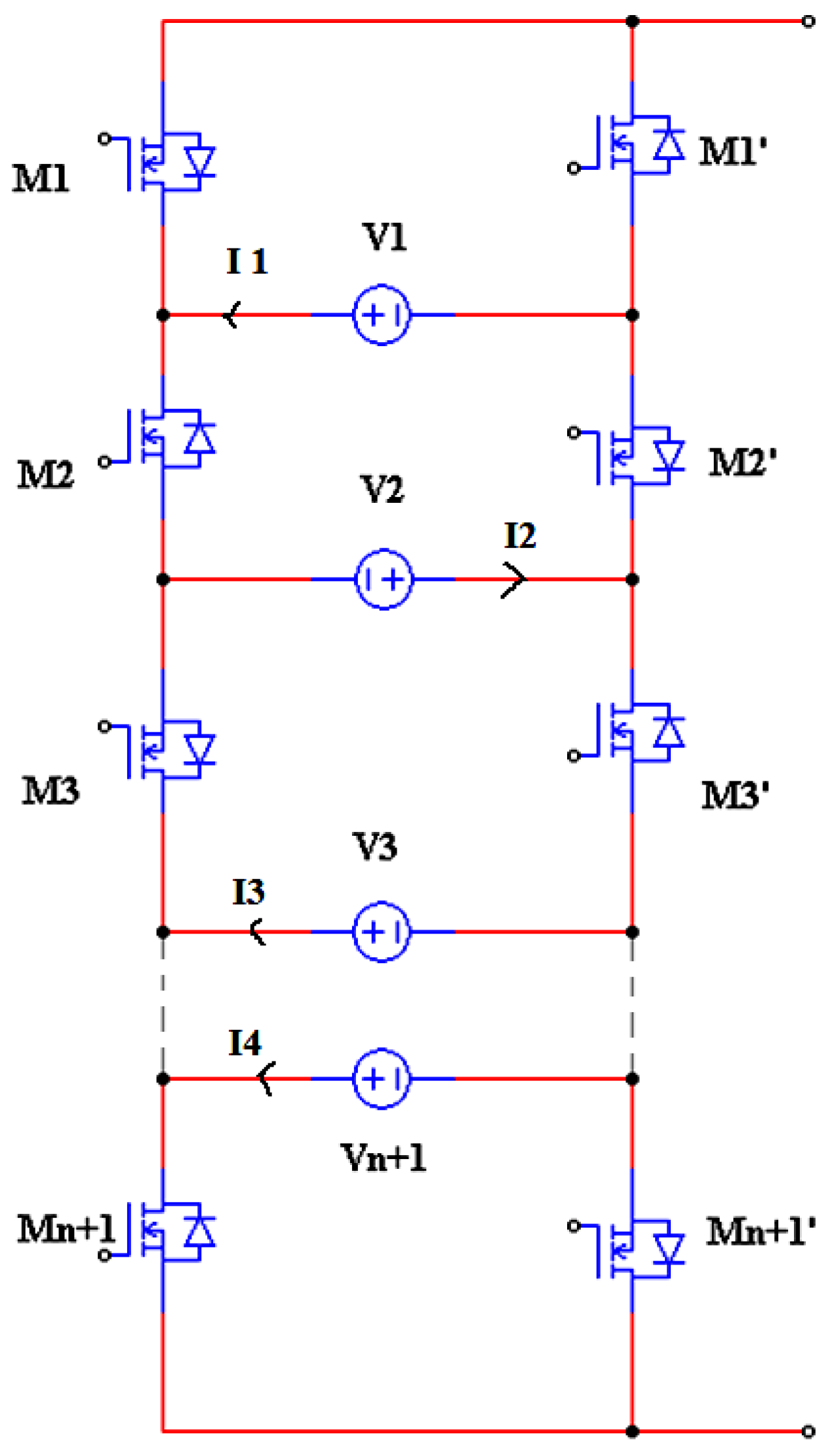
4.2. Reverse Connected Voltage Source MLI

The reverse connected topology was discussed by the authors for MLIs starting with five-level voltages in [81]. An H-bridge configuration with four main switches and a single voltage source acts as the main circuit. One leg of the main circuit had complementary switches and reverse-connected voltage sources. To extract N-level output voltage, N + 3 switches had to be used. The circuit topology is shown in Figure 49.

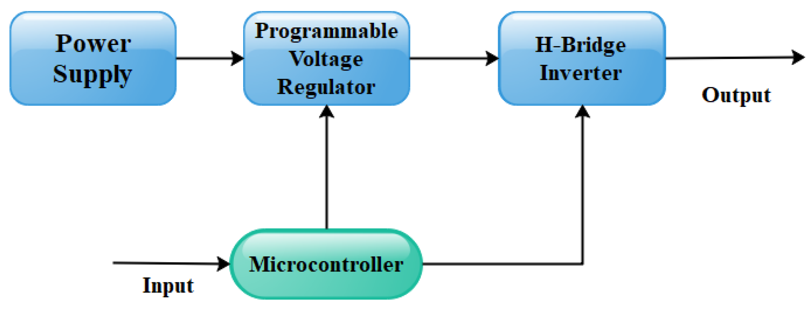
4.3. Implementation of MLI Using LM350 Voltage Regulator

A five-level inverter using an LM350 voltage regulator was implemented in [82] for low power applications, typically in the range of 30 W. With reference to the data sheet of LM350, the parameters were chosen for the design of inverter. The different values of output voltages were obtained by adjusting the terminals of the LM350 IC where the series biasing resistors were also connected. A microcontroller is employed for the proper selection of resistor. The desired values were generated by operating the inverter using a control program. The concept is explained with the help of a block diagram shown in Figure 50.

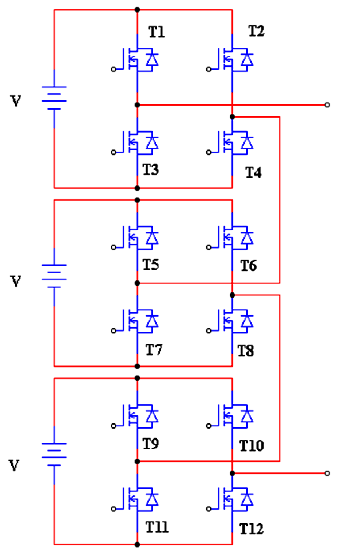
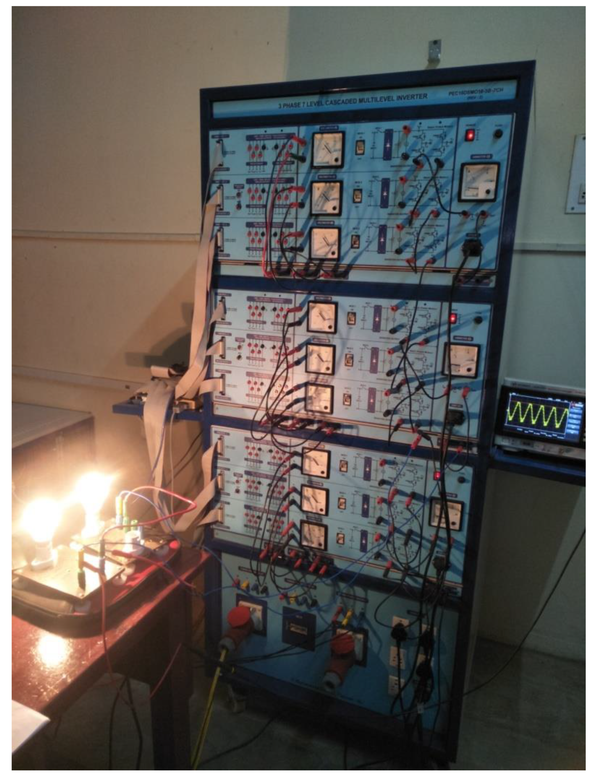
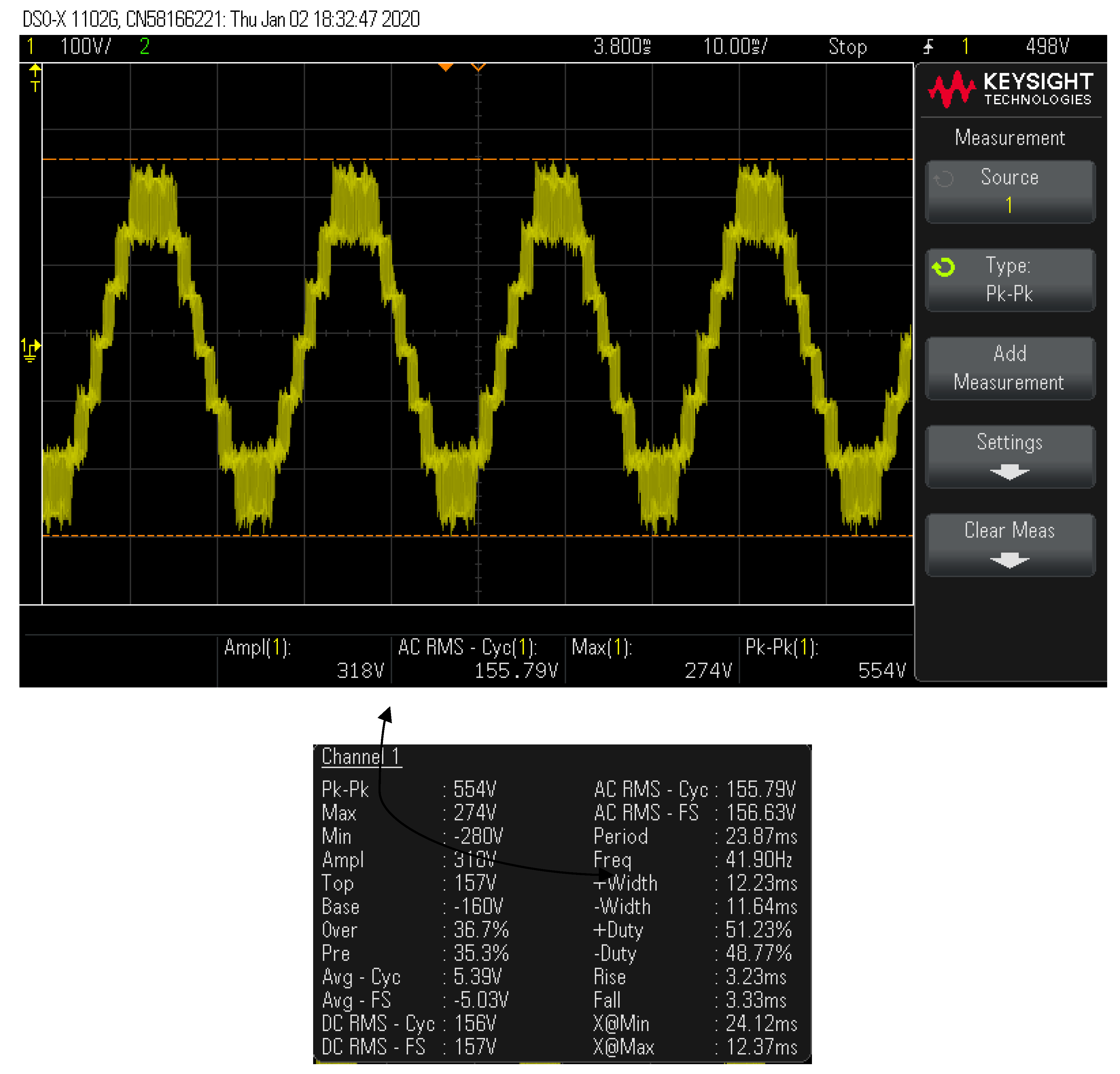
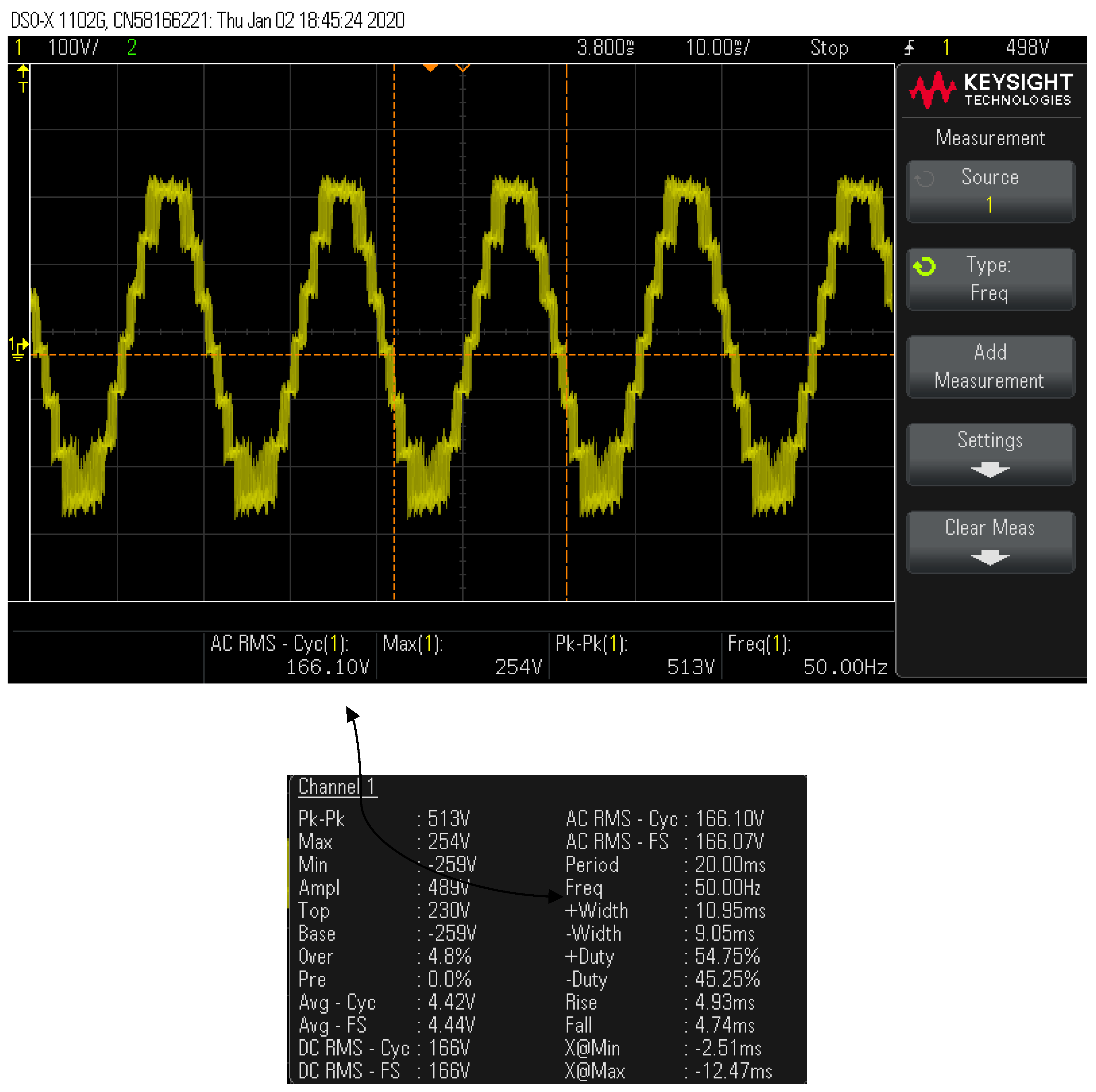
4.4. Hardware Implementation of Cascaded Seven Level Inverter

The hardware prototype was implemented for a conventional cascaded seven-level inverter at R&D Power Electronics Laboratory of SEEE, at SASTRA Deemed University and the readings were noted. The overall circuit comprised several H-bridge inverters, which were connected in series to provide a sinusoidal output voltage. The inverter was divided into number of cells associated with an H-bridge in each cell and the voltage could be obtained by adding the values of voltage generated by each cell. For example, if there are k cells in an H-bridge multilevel inverter then the number of output voltage levels was 2k + 1.
Cascaded inverters are more advantageous when compared to other two conventional types as they require fewer components than the other configurations. This results in weight and cost reduction of the overall system. Figure 51 shows a k level cascaded H-bridge inverter.
The cyclone IV FPGA controller was employed in the control unit of multilevel inverter. The hardware was set up and configured in the R&D lab at SASTRA Deemed University, India for the circuit topology shown in Figure 52.
The inverter operated under open-loop and closed-loop conditions with a motor load at the speed of 1300 rpm. In order to measure the voltage, a set of lamps was connected across a phase and the readings were noted. The generated waveforms for the output voltage under open-loop and closed-loop conditions were shown in Figure 53 and Figure 54 respectively.
From Figure 53 and Figure 54, it can be clearly observed that the inverter generated seven levels of output at a maximum of 274 V and 254 V respectively.

5. Conclusions

Multilevel inverters have become one of the major devices in the field of power electronics since they can be used for both high-power and high-voltage applications. The multilevel inverter has more benefits too, such as high resolution, low modularity, reduced switch count for higher levels of voltage and in terms of its control mechanism. This work has been carried out in such a way that it covers the different configurations based on its structure and number of devices, the modulation techniques and some special methodologies for using MLI in a unique manner with certain modifications over the other versions. This review will serve as a point of reference for researchers those who are working in this field.

Author Contributions

S.P.S. performed the review under the guidance and direction of S.S.R. and S.N who devised the idea. All three authors analyzed the data and contributed towards the review. S.P.S. wrote the paper and executed the experiments under the guidance and supervision of S.S.R. and S.N. All authors have read and agreed to the published version of the manuscript.

Funding

This research received no external funding.

Acknowledgments

Authors would like to thank the management of SASTRA Deemed University and the R& D lab at Power electronics and drives laboratory of SEEE at SASTRA University for providing necessary facilities to carry out the research.

Conflicts of Interest

The authors declare no conflict of interest.

References

  1. Krishna, R.A.; Suresh, L.P. A Brief Review on Multi Level Inverter Topologies. In Proceedings of the 2016 International Conference on Circuit, Power and Computing Technologies (ICCPCT), Nagercoil, India, 18–19 March 2016; pp. 1–6. [Google Scholar]
  2. Babaei, E.; Kangarlu, M.F.; Mazgar, F.N. Symmetric and asymmetric multilevel inverter topologies with reduced switching devices. Electr. Power Syst. Res. 2012, 86, 122–130. [Google Scholar] [CrossRef]
  3. Babaei, E. A Cascade Multilevel Converter Topology With Reduced Number of Switches. IEEE Trans. Power Electron. 2008, 23, 2657–2664. [Google Scholar] [CrossRef]
  4. Ahmed, R.A.; Ping, H.W. New multilevel inverter topology with minimum number of switches. In Proceedings of the TENCON 2010—2010 IEEE Region 10 Conference, Fukuoka, Japan, 21–24 November 2010; pp. 1862–1867. [Google Scholar]
  5. Umashankar, S.; Sreedevi, T.S.; Nithya, V.G.; Vijayakumar, D. A New 7-Level Symmetric Multilevel Inverter with Minimum Number of Switches. ISRN Electron. 2013, 2013, 476876. [Google Scholar] [CrossRef]
  6. Veenstra, M.; Rufer, A.; Member, S. Control of a Hybrid Asymmetric Multilevel Inverter for Competitive Medium-Voltage Industrial Drives. IEEE Trans. Ind. Appl. 2005, 41, 655–664. [Google Scholar] [CrossRef]
  7. Ceglia, G.; Guzmán, V.; Sánchez, C.; Ibáñez, F.; Walter, J.; Giménez, M.I. A New Simplified Multilevel Inverter Topology for DC—AC Conversion. IEEE Trans. Power Electron. 2006, 21, 1311–1319. [Google Scholar] [CrossRef]
  8. Najafi, E.; Halim, A.; Yatim, M.; Member, S. Design and Implementation of a New Multilevel Inverter Topology. IEEE Trans. Ind. Electron. 2012, 59, 4148–4154. [Google Scholar] [CrossRef]
  9. Poyyamani Sunddararaj, S.; Rangarajan, S.S.; Gopalan, S. Neoteric Fuzzy Control Stratagem and Design of Chopper fed Multilevel Inverter for Enhanced Voltage Output Involving Plug-In Electric Vehicle (PEV) Applications. Electronics 2019, 8, 1092. [Google Scholar] [CrossRef] [Green Version]
  10. Rangarajan, S.S.; Collins, E.R.; Fox, J.C. Smart PV and SmartPark inverters as suppressors of TOV phenomenon in distribution systems. IET Gener. Transm. Distrib. 2018, 12, 5909–5917. [Google Scholar] [CrossRef]
  11. Prakash, S.; Kumar, L.; Gupta, S.; Agrawal, N. Implementation of Symmetrical Multilevel Inverter Topology. In Proceedings of the 2016 IEEE 1st International Conference on Power Electronics, Intelligent Control and Energy Systems (ICPEICES), Delhi, India, 4–6 July 2016; pp. 1–6. [Google Scholar]
  12. Bharath, K.; Satputaley, R.J. Single phase asymmetrical cascaded multilevel inverter design for induction motor. IJEEDC 2011, 1, 8–13. [Google Scholar]
  13. Jana, P.; Chattopadhyay, S.; Bajpai, P.; Chakraborty, C. Asymmetrical Cascaded Multilevel Inverter with Single DC Source Using High Frequency Resonant Converter. In Proceedings of the 2016 IEEE Students’ Technology Symposium (TechSym), Kharagpur, India, 30 September–2 October 2016; pp. 73–78. [Google Scholar]
  14. Seth, N.; Goel, V.; Kulkarni, R.D.; Joshi, V.P. Performance analysis of seven level three phase asymmetric multilevel Inverter at various modulation indices. In Proceedings of the 2016 International Conference on Electrical Power and Energy Systems (ICEPES), Bhopal, India, 14–16 December 2017; pp. 407–413. [Google Scholar]
  15. Raman, S.R.; Cheng, K.W.E.; Hu, J. A seven level switched capacitor multilevel inverter with asymmetric input sources for microgrids. In Proceedings of the 2017 20th International Conference on Electrical Machines and Systems (ICEMS), Sydney, NSW, Australia, 11–14 August 2017; pp. 2–7. [Google Scholar]
  16. Agrawal, N.; Bansal, P. A new 21-level asymmetrical multilevel inverter topology with different PWM techniques. In Proceedings of the 2017 Recent Developments in Control, Automation & Power Engineering (RDCAPE), Noida, India, 26–27 October 2017; Volume 3, pp. 224–229. [Google Scholar]
  17. Pires, V.F.; Silva, J.F. Hybrid Cascade Multilevel Inverter Using a Single DC Source for Open-End Winding Induction Motors. In Proceedings of the 2012 IEEE International Conference on Industrial Technology, Athens, Greece, 19–21 March 2012; pp. 966–970. [Google Scholar]
  18. Sujitha, N.; Ramani, K. A New Hybrid Cascaded H-Bridge Multilevel Inverter—Performance Analysis. In Proceedings of the IEEE-International Conference On Advances In Engineering, Science And Management (lCAESM-2012), Nagapattinam, Tamil Nadu, India, 30–31 March 2012; pp. 46–50. [Google Scholar]
  19. Satheeswaran, K.; Ramani, K. Reformed Hybrid Multilevel Inverter Through Photovoltaic for Induction Motor. In Proceedings of the 2014 International Conference on Green Computing Communication and Electrical Engineering (ICGCCEE), Coimbatore, India, 6–8 March 2014. [Google Scholar]
  20. Manjunatha, Y.R. Simulation and Implementation of FPGA Based Hybrid Asymmetric Multilevel Inverter. In Proceedings of the 2015 International Conference on Emerging Research in Electronics, Computer Science and Technology (ICERECT), Mandya, India, 17–19 December 2015; pp. 452–456. [Google Scholar]
  21. Satish, S.; Sasikumar, M. An Approach of Hybrid Modulation in Fusion seven-level Cascaded Multilevel Inverter accomplishment to IM drive system. In Proceedings of the 2016 Second International Conference on Science Technology Engineering and Management (ICONSTEM), Chennai, India, 30–31 March 2016; pp. 383–387. [Google Scholar]
  22. Gurpinar, E.; Castellazzi, A. Novel Multilevel Hybrid Inverter Topology with Power Scalability. In Proceedings of the IECON 2016—42nd Annual Conference of the IEEE Industrial Electronics Society, Florence, Italy, 23–26 October 2016; pp. 6516–6521. [Google Scholar]
  23. Gurpinar, D.E.; De Castellazzi, A. Power Converter. GB Patent Application No. 1520961.2, 27 November 2015. [Google Scholar]
  24. Sekhar, C.P. Novel Multilevel Inverter With Minimum Number Of Switches. In Proceedings of the 2017 International Conference on Recent Trends in Electrical, Electronics and Computing Technologies (ICRTEECT), Warangal, India, 30–31 July 2017; pp. 106–112. [Google Scholar]
  25. Chulan, M.; Aziz, J.; Yatim, A.H.; Daud, M. Seven Levels Symmetric H-Bridge Multilevel Inverter with Less Number of Switching Devices. IJPEDS 2017, 8, 109. [Google Scholar] [CrossRef] [Green Version]
  26. Nedumgatt, J.J.; Kumar, D.V.; Kirubakaran, A.; Umashankar, S. A multilevel inverter with reduced number of switches. In Proceedings of the 2012 IEEE Students’ Conference on Electrical, Electronics and Computer Science (SCEECS), Bhopal, India, 1–2 March 2012; pp. 1–4. [Google Scholar]
  27. Prabaharan, N.; Salam, Z.; Cecati, C.; Palanisamy, K. Design and implementation of new multilevel inverter topology for trinary sequence using unipolar pulse width modulation. IEEE Trans. Ind. Electron. 2019. [Google Scholar] [CrossRef]
  28. Karthikeyan, D.; Kubendran, V.; Vijayakumar, K.; Saurabh, S.; Singh, V. Implementation of Novel Multi Level Inverter Topology with Reduced Number of Power Components. IJRTE 2019, 8, 577–587. [Google Scholar]
  29. Sharifabadi, K.; Harnefors, L.; Nee, H.P.; Norrga, S.; Teodorescu, R. Desgin, Control and Application of Modular Multilevel Converters for HVDC Transmission Systems; John Wiley & Sons: Hoboken, NJ, USA, 2016. [Google Scholar]
  30. Ahmed, H.; Nayak, A.K. Modified Cascaded Multilevel Inverter with Reduced Component Count. In Proceedings of the 2017 14th IEEE India Council International Conference (INDICON), Roorkee, India, 15–17 December 2017; pp. 2–6. [Google Scholar]
  31. Deepak, R.; Vishnu, S. Novel Multilevel Inverter with Reduced Number of Switches and Batteries. In Proceedings of the 2013 International conference on Circuits, Controls and Communications (CCUBE), Bengaluru, India, 27–28 December 2013. [Google Scholar]
  32. Abraham, B.T.; Benny, A. Asymmetric Multilevel Hybrid Inverter with Reduced Number of Switches. In Proceedings of the 2014 Annual International Conference on Emerging Research Areas: Magnetics, Machines and Drives (AICERA/iCMMD), Kottayam, India, 24–26 July 2014. [Google Scholar]
  33. Wu, B.; Mehdi, N. High-Power Converters and AC Drives; John Wiley & Sons: Hoboken, NJ, USA, 2017. [Google Scholar]
  34. Salem, A.; Ahmed, E.M.; Orabi, M.; Abdelghani, A. Ben Novel Three-Phase Multilevel Voltage Source Inverter with Reduced No. of Switches. In Proceedings of the 2014 5th International Renewable Energy Congress (IREC), Hammamet, Tunisia, 25–27 March 2014; Volume 2, pp. 2–6. [Google Scholar]
  35. Sarbanzadeh, M.; Member, S.; Babaei, E.; Hosseinzadeh, M.A.; Cecati, C. A New Sub-Multilevel Inverter with Reduced Number of Components. In Proceedings of the IECON 2016—42nd Annual Conference of the IEEE Industrial Electronics Society, Florence, Italy, 23–26 October 2016; pp. 3166–3171. [Google Scholar]
  36. Kumar, J. A New Cross Switched Cascaded Multilevel Inverter Topology with Reduced Number of Switches. In Proceedings of the 2016 IEEE 7th Power India International Conference (PIICON), Bikaner, India, 25–27 November 2016. [Google Scholar]
  37. Prabaharan, N. A New Hybrid Asymmetric Multilevel Inverter with Reduced Number Of Switches. In Proceedings of the 2016 IEEE International Conference on Power Electronics, Drives and Energy Systems (PEDES), Trivandrum, India, 14–17 December 2016; pp. 1–4. [Google Scholar]
  38. Noyal, M.A.; Ananthi, D.A.; Raja, C. Modified hybrid multilevel inverter with reduced number of switches for PV application with smart IoT system. J. Ambient Intell. Humaniz. Comput. 2018. [Google Scholar] [CrossRef]
  39. Liu, J.; Wu, J.; Zeng, J.; Guo, H. A Novel Nine-Level Inverter Employing One Voltage Source and Reduced Components as High Frequency AC Power Source. IEEE Trans. Power Electron. 2016, 32. [Google Scholar] [CrossRef]
  40. Babaei, E.; Gowgani, S.S. Hybrid multilevel inverter using switched capacitor units. IEEE Trans. Ind. Electron. 2014, 61, 4614–4621. [Google Scholar] [CrossRef]
  41. Hemachandu, P.; Reddy, V.C.V.; Reddy, V.C.J.M.; Reddy, V.U. A PV/FC co-generation based micro-grid system using compact integrated 7- level inverter. In Proceedings of the 2015 Conference on Power, Control, Communication and Computational Technologies for Sustainable Growth (PCCCTSG), Kurnool, India, 11–12 December 2015; pp. 252–258. [Google Scholar]
  42. Prabaharan, N.; Palanisamy, K. A single phase grid connected hybrid multilevel inverter for interfacing photo-voltaic system. Energy Procedia 2016, 103, 250–255. [Google Scholar] [CrossRef]
  43. Gupta, K.K.; Jain, S.; Member, S. A Novel Multilevel Inverter Based on Switched DC Sources. IEEE Trans. Ind. Electron. 2014, 61, 3269–3278. [Google Scholar] [CrossRef]
  44. Patel, D.; Ramesh, R. A Review of Various Carrier based PWM Methods for Multilevel Inverter. In Proceedings of the India International Conference on Power Electronics 2010 (IICPE2010), New Delhi, India, 28–30 January 2011; pp. 1–6. [Google Scholar]
  45. Manimala, V. Design and Simulation of Five Level Cascaded Inverter using Multilevel Sinusoidal Pulse Width Modulation Strategies. In Proceedings of the 2011 3rd International Conference on Electronics Computer Technology, Kanyakumari, India, 8–10 April 2011; pp. 280–283. [Google Scholar]
  46. Naderi, R.; Rahmati, A. Phase-shifted carrier PWM technique for general cascaded inverters. IEEE Trans. Power Electron. 2008, 23, 1257–1269. [Google Scholar] [CrossRef]
  47. Carrara, G.; Gardella, S.; Marchesoni, M.; Salutari, R.; Sciutto, G. A new multilevel PWM method: A theoretical analysis. IEEE Trans. Power Electron. 1992, 7, 497–505. [Google Scholar] [CrossRef]
  48. Zhao, J.; He, X.; Zhao, R. A novel pwm control method for hybrid-clamped multilevel inverters. IEEE Trans. Ind. Electron. 2010, 57, 2365–2373. [Google Scholar] [CrossRef]
  49. Kanimozhi, M.; Geetha, P. A New Boost Switched Capacitor Multilevel Inverter Using Different Multi Carrier PWM Techniques. In Proceedings of the 2014 International Conference on Circuits, Power and Computing Technologies [ICCPCT-2014], Nagercoil, India, 20–21 March 2014; pp. 432–437. [Google Scholar]
  50. Sedghi, S.; Dastfan, A.; Ahmadyfard, A. A New Multilevel Carrier Based Pulse Width Modulation Method For modular Multilevel Inverter. In Proceedings of the 8th International Conference on Power Electronics—ECCE Asia, Jeju, Korea, 30 May–3 June 2011. [Google Scholar]
  51. Sarkar, I.; Fernandes, B.G. Modified Hybrid Multi-Carrier PWM Technique for Cascaded H-Bridge Multilevel Inverter. In Proceedings of the IECON 2014—40th Annual Conference of the IEEE Industrial Electronics Society, Dallas, TX, USA, 29 October–1 November 2014. [Google Scholar]
  52. Agelidis, V.G.; Calais, M. Application specific harmonic performance evaluation of multicarrier PWM techniques. In Proceedings of the IEEE Power Electronics Specialists Conference (PESC), Fukuoka, Japan, 17–22 May 1998; Volume 1, pp. 172–178. [Google Scholar]
  53. Karthika, B.; Sasikumar, M. Analysis of Hybrid PWM Control Schemes for Cascaded Multilevel Inverter Fed Industrial Drives. In Proceedings of the 2014 International Conference on Circuits, Power and Computing Technologies [ICCPCT-2014], Nagercoil, India, 20–21 March 2014; pp. 745–750. [Google Scholar]
  54. Rushiraj, G.J.; Kapil, P.N. Analysis of Different Modulation Techniques for Multilevel Inverters. In Proceedings of the 2016 International Conference on Electrical, Electronics, and Optimization Techniques (ICEEOT), Chennai, India, 3–5 March 2016; pp. 3017–3022. [Google Scholar]
  55. Hava, A.M.; Kerkman, R.J.; Lipo, T.A. Simple Analytical and Graphical Methods for Carrier-Based PWM-VSI Drives. IEEE Trans. Power Electron. 1999, 14, 49–61. [Google Scholar] [CrossRef]
  56. Patil, S.D.; Kadwane, S.G.; Gawande, S.P. Ant colony optimization applied to selective harmonic elimination in multilevel inverters. In Proceedings of the 2016 2nd International Conference on Applied and Theoretical Computing and Communication Technology (iCATccT), Bangalore, India, 21–23 July 2016; pp. 637–640. [Google Scholar]
  57. Kouro, S.; Malinowski, M.; Gopakumar, K.; Pou, J.; Franquelo, L.G.; Wu, B.; Rodriguez, J.; Pérez, M.A.; Leon, J.I. Recent Advances and Industrial Applications of Multilevel Converters. IEEE Trans. Ind. Electron. 2010, 57, 2553–2580. [Google Scholar] [CrossRef]
  58. Mamatha, P. Performance Improved Multilevel Inverter with Selective Harmonic Elimination. In Proceedings of the 2017 International Conference on Recent Trends in Electrical, Electronics and Computing Technologies (ICRTEECT), Warangal, India, 30–31 July 2017; pp. 1–6. [Google Scholar]
  59. Muthuramalingam, A.; Balaji, M.; Himavathi, S. Selective Harmonic Elimination Modulation Method for Multilevel Inverters. In Proceedings of the 2006 India International Conference on Power Electronics, Chennai, India, 19–21 December 2006; pp. 40–45. [Google Scholar]
  60. Van Der Broeck, H.W.; Skudelny, H.C.; Stanke, G.V. Analysis and Realization of a Pulsewidth Modulator Based on Voltage Space Vectors. IEEE Trans. Ind. Appl. 1988, 24, 142–150. [Google Scholar] [CrossRef]
  61. AS, A.M.; Gopinath, A.; Baiju, M.R. A Simple Space Vector PWM Generation for any General NLevel Inverter. IEEE Trans. Ind. Electron. 2009, 56, 1649–1656. [Google Scholar]
  62. Yao, W.; Hu, H.; Lu, Z. Comparoson of Space Vector Modulation and Carrier based Modulation of Multilevel Inverter. IEEE Trans. Power Electron. 2008, 23, 45–51. [Google Scholar] [CrossRef]
  63. Wei, S.; Wu, B.; Li, F.; Liu, C. A General Space Vector PWM Control Algorithm for Multilevel Inverters. In Proceedings of the Eighteenth Annual IEEE Applied Power Electronics Conference and Exposition, 2003. APEC ′03, Miami Beach, FL, USA, 9–13 February 2003; pp. 562–568. [Google Scholar]
  64. Seo, J.H.; Choi, C.H.; Hyun, D.S. A New Simplified Space Vector PWM Method for Three-Level Inverters. IEEE Trans. Power Electron. 2001, 16, 545–550. [Google Scholar]
  65. Kim, J.-S.; Sul, S.-K. A Novel Voltage Modulation Technique of the Space Vector PWM. In Proceedings of the 1995 International Power Electronics Conference IPEC Yokohama-95, Yokohama, Japan, 3–7 April 1995; pp. 742–747. [Google Scholar]
  66. Gopinath, A.; AS, A.M.; Baiju, M.R. Fractal Based Space Vector PWM for Multilevel Inverters—A Novel Approach. IEEE Trans. Ind. Electron. 2009, 52, 1230–1238. [Google Scholar] [CrossRef]
  67. Seixas, P.F.; Mendes, M.S.; Donoso-Garcia, P.; Lima, A.M.N. A Space Vector PWM Method for Three-Level Voltage Source Inverters. In Proceedings of the APEC 2000. Fifteenth Annual IEEE Applied Power Electronics Conference and Exposition (Cat. No.00CH37058), New Orleans, LA, USA, 6–10 February 2000; pp. 549–555. [Google Scholar]
  68. Shivakumar, E.G.; Gopakumar, K.; Sinha, S.K.; Pittet, A.; Ranganathan, V.T. Space Vector PWM control of dual inverter fed open- end winding induction motor drive. In Proceedings of the Applied Power Electronics Conference (APEC), Anaheim, CA, USA, 4–8 March 2001; pp. 399–405. [Google Scholar]
  69. Shiny, G.; Baiju, M.R. A Low Computation Space Vector PWM Scheme for Multilevel Inverters based on Fractal Approach. In Proceedings of the 2010 IEEE Symposium on Industrial Electronics and Applications (ISIEA), Penang, Malaysia, 3–5 October 2010; pp. 131–136. [Google Scholar]
  70. Sreeja, C. A Novel Control Algorithm for Three Phase Multilevel Inverter using SVM. In Proceedings of the ISGT2011-India, Kollam, Kerala, India, 1–3 December 2011. [Google Scholar]
  71. Zhang, H.; Von Jouanne, A.; Dai, S.; Wallace, A.K.; Wang, F. Multilevel inverter modulation schemes to eliminate common-mode voltages. IEEE Trans. Ind. Appl. 2000, 36, 1645–1653. [Google Scholar]
  72. Suh, J.; Choi, C.; Hyun, D. A new simplified space-vector PWM method for three-level inverters. In Proceedings of the Applied Power Electronics Conference and Exposition (APEC), Dallas, TX, USA, 14–18 March 1999; pp. 515–520. [Google Scholar]
  73. Celanovic, N.; Boroyevich, D. A fast space vector modulation algorithm for multilevel three phase converters. IEEE Trans. Ind. Appl. 2001, 37, 637–641. [Google Scholar] [CrossRef]
  74. Gupta, A.K.; Khambadkone, A.M. A space vector PWM scheme for multilevel inverters based on two-level space vector PWM. IEEE Trans. Ind. Electron. 2006, 53, 1631–1639. [Google Scholar] [CrossRef]
  75. Shiny, G. A General Modulation Strategy for Multilevel Inverters using SVPWM Approach. In Proceedings of the 2016 IEEE International Conference on Power Electronics, Drives and Energy Systems (PEDES), Trivandrum, India, 14–17 December 2016. [Google Scholar]
  76. Prasad, K.N.; ParimitaPradhan, P.; Misra, B.; Surekha, J. Modified Space Vector Algorithm For 5-Level Cascaded Multilevel Inverter. In Proceedings of the 2017 Innovations in Power and Advanced Computing Technologies (i-PACT), Vellore, India, 21–22 April 2017; pp. 1–6. [Google Scholar]
  77. Kale, A.S. Comparative Study of SPWM and SVPWM Cascaded H-bridge Multilevel Inverter. In Proceedings of the 2017 International Conference on Intelligent Computing and Control (I2C2), Coimbatore, India, 23–24 June 2017. [Google Scholar]
  78. Karuppanan, P.; Mahapatra, K.K. FPGA based Cascaded Multilevel Pulse Width Modulation for Single Phase Inverter. In Proceedings of the 2010 9th International Conference on Environment and Electrical Engineering, Prague, Czech Republic, 16–19 May 2010; pp. 273–276. [Google Scholar]
  79. Jeevananthan, S.; Prabu, L.M.; Dananjayan, P. Evolutionary computing based area integration PWM technique for multilevel inverters. In Proceedings of the 2006 India International Conference on Power Electronics, Chennai, India, 19–21 December 2006; pp. 62–67. [Google Scholar]
  80. Najafi, E.; Yatim, A.H. Design and Implementation of a New Multilevel Inverter Topology. IEEE Trans. Ind. Electron. 2012, 59, 4148–4154. [Google Scholar] [CrossRef]
  81. Agrawal, N.; Tomar, S.S.; Bansal, P. A Multilevel Inverter Topology using Reverse- Connected Voltage Sources. In Proceedings of the 2017 International Conference on Energy, Communication, Data Analytics and Soft Computing (ICECDS), Chennai, India, 1–2 August 2017; pp. 1290–1295. [Google Scholar]
  82. Ali, R.; Daut, I.; Taib, S.; Jamoshid, N.S. A 5-Level Multilevel Inverter Using LM350 Voltage Regulator IC. In Proceedings of the 2010 4th International Power Engineering and Optimization Conference (PEOCO), Shah Alam, Malaysia, 23–24 June 2010; pp. 137–141. [Google Scholar]
Figure 1. Basic classification of multilevel inverters (MLI).
Electronics 09 00433 g001
Figure 2. Classification of MLI types and techniques.
Electronics 09 00433 g002
Figure 3. Circuit of 11-level inverter.
Electronics 09 00433 g003
Figure 4. Circuit of seven-level five-switch inverter.
Electronics 09 00433 g004
Figure 5. MLI with reduced number of switches.
Electronics 09 00433 g005
Figure 6. Cascaded MLI circuit.
Electronics 09 00433 g006
Figure 7. Seven-level cascaded type H-bridge MLI.
Electronics 09 00433 g007
Figure 8. High frequency asymmetric MLI.
Electronics 09 00433 g008
Figure 9. Circuit for seven-level cascaded MLI.
Electronics 09 00433 g009
Figure 10. MLI based on switched capacitor.
Electronics 09 00433 g010
Figure 11. Equivalent circuit for full bridge MLI for 21 levels of output.
Electronics 09 00433 g011
Figure 12. Hybrid three-phase multilevel inverter.
Electronics 09 00433 g012
Figure 13. Circuit diagram for three-phase MLI.
Electronics 09 00433 g013
Figure 14. Circuit diagram for three-phase MLI.
Electronics 09 00433 g014
Figure 15. MLI based on switched capacitor.
Electronics 09 00433 g015
Figure 16. Circuit of hybrid cell technology for MLI.
Electronics 09 00433 g016
Figure 17. Circuit configuration for Neutral Point Clamped (NPC) type MLI.
Electronics 09 00433 g017
Figure 18. Circuit for modified MLI with minimum number of switches.
Electronics 09 00433 g018
Figure 19. Circuit for seven-level H-bridge inverter.
Electronics 09 00433 g019
Figure 20. Nine-level inverter circuit.
Electronics 09 00433 g020
Figure 21. Multilevel inverter to reduce switching losses.
Electronics 09 00433 g021
Figure 22. Reduced switch MLI circuit.
Electronics 09 00433 g022
Figure 23. Basic unit and nine-level MLI.
Electronics 09 00433 g023
Figure 24. Basic unit and nine-level MLI.
Electronics 09 00433 g024
Figure 25. Novel reduced switch MLI.
Electronics 09 00433 g025
Figure 26. Generalized three-level NPC circuit.
Electronics 09 00433 g026
Figure 27. MLI circuit (symmetric mode).
Electronics 09 00433 g027
Figure 28. MLI circuit (asymmetric mode).
Electronics 09 00433 g028
Figure 29. Bidirectional switch MLI circuit.
Electronics 09 00433 g029
Figure 30. Bidirectional switch MLI circuit.
Electronics 09 00433 g030
Figure 31. Circuit configuration for asymmetric MLI.
Electronics 09 00433 g031
Figure 32. Block diagram for multilevel inverter circuit.
Electronics 09 00433 g032
Figure 33. Circuit diagram for nine-level Inverter.
Electronics 09 00433 g033
Figure 34. Circuit diagram for hybrid MLI.
Electronics 09 00433 g034
Figure 35. Waveform for phase disposition.
Electronics 09 00433 g035
Figure 36. Waveform for phase opposition method.
Electronics 09 00433 g036
Figure 37. Waveform for alternate phase opposition method.
Electronics 09 00433 g037
Figure 38. Conventional PWM signal.
Electronics 09 00433 g038
Figure 39. Modified PWM signal.
Electronics 09 00433 g039
Figure 40. Waveform for hybrid PWM technique.
Electronics 09 00433 g040
Figure 41. Depenbrock’s PWM-1 phase waveform.
Electronics 09 00433 g041
Figure 42. Depenbrock’s PWM-3 phase waveform.
Electronics 09 00433 g042
Figure 43. Model waveform for Selective Harmonic Elimination (SHE) method.
Electronics 09 00433 g043
Figure 44. Sixty-degree coordination system for five-level inverter.
Electronics 09 00433 g044
Figure 45. Sixty degree Space Vector Pulse Width Modulation (SVPWM) technique.
Electronics 09 00433 g045
Figure 46. Control using FPGA.
Electronics 09 00433 g046
Figure 47. Basic schematic showing Area Integration Pulse Width Modulation (AIPWM) technique.
Electronics 09 00433 g047
Figure 48. Circuit diagram for switched DC-source MLI.
Electronics 09 00433 g048
Figure 49. Reverse connected voltage source MLI.
Electronics 09 00433 g049
Figure 50. Block diagram for concept of MLI using LM350.
Electronics 09 00433 g050
Figure 51. Circuit diagram for cascade H-bridge inverter.
Electronics 09 00433 g051
Figure 52. Hardware setup for seven-level cascade inverter at Shanmugha Arts, Science, Technology & Research Academy (SASTRA).
Electronics 09 00433 g052
Figure 53. Output voltage waveform under open loop condition.
Electronics 09 00433 g053
Figure 54. Output voltage waveform under closed loop condition.
Electronics 09 00433 g054
Table 1. Classification of MLI based on its number of elements and structure.
Paper Reference Number and YearType of InverterNo. of DC SourcesNo. of Switching DevicesNumber of DiodesNo. of Voltage LevelsVoltage Gain and No. of Voltage Levels FormulaSwitching TechniquesLimitationsAdvantages
[4] & 2010Symmetric38011Vo,max = n*VdcCarrier redistribution (CR) technique-A new algorithm has been proposed for the generation of maximum voltage without losing any level in output voltage waveform.
[5] & 2013Symmetric4507☐ = (2 × ∗ ☐ − 3)Carrier based PWM techniqueFails to determine suitable PWM techniqueLower THD level
[11] & 2016Symmetric4739-Multicarrier PWM techniqueIt cannot be implemented for medium to high voltage applicationCost is very low for designing the same level of voltage when compared with conventional method
[11] & 2016Symmetric(modified)41029-Multicarrier PWM techniqueThe values of dc sources get increased proportionally in the range of ‘5:1’ for all ‘k’ number of cells.It is applicable to wide range of voltage applications
[12] & 2013Asymmetric2807Vo, max = (2N+1-1)VdcLevel Shifted PWM techniqueUnique filter design is required to reduce harmonicsLower THD level
[13] & 2016Asymmetric21027(P1/P0) = (V1/Vo)On/OFF controlProper PWM technique is not implementedSuitable for medium power application such as PV, fuel cell, and battery application
[14] & 2016Asymmetric cascaded MLI61207M = Am/(Ac(k-1))Multicarrier PWM techniqueNumber of switches are highIt can be utilized in crucial industrial applications.
[16] & 2017Asymmetric412021-Multicarrier PWM techniqueProper voltage balancing is requiredRequires less number of devices
[17] & 2012Hybrid1 (along with 4 capacitors)1809-SPWM techniqueComplex control strategyThe capacitor voltage of single phase inverters are regulated by a sliding mode control
[18] & 2012Hybrid1 (along with 4 capacitors)1809Lph = 2Ninv + 1Fundamental switching schemeNo modification has been made in carrier or modulating signalNeed for large inductor is eliminated
[19]Hybrid3739V = 2S − 1.VdcNot definedProper PWM technique is not implementedProduces high number of levels with less number of switches
[20] & 2015Hybrid212025Vk = (5 kí1) V1.Symmetrical Step Control Method & Fundamental Switching Frequency SchemeSymmetrical step control doest not give efficient resultsTHD is low while using fundamental frequency technique
[21] & 2016Hybrid1 (along with 3 capacitors)607Vndc = (N − 1)/2Hybrid Modulation-THD is 3.21%
[24] & 2017Reduced Switch MLI2607-Not definedProper PWM technique is not implementedThe conversion efficiency of the converter increases because of less number of switches.
[26] & 2014Reduced Switch MLI3907-Multicarrier APOD technique-Reduced switch count
[27] & 2019Reduced Switch MLI2909kVdcPhase dispositionComplex control strategyUtilization of a novel converter using voltage multiplier concept reduces the DC source count.
[28]Reduced Switch MLI4809-Phase Opposition Disposition-Minimized THD and Switching losses
[30]Reduced Switch MLI15211Vo = nVdcMulticarrier based level-shift PWM-Reduced Power loss
[31]Reduced Switch MLI2809V = V1 + V2Not definedProper PWM technique is not implemented and filter design is required to reduce harmonicsReduced switch count
[38] & 2016Reduced Switch MLI1929-High Frequency ModulationComplex control strategyTHD is low and the voltage stress on the power switches in the back-stage is relatively relieved

