Article

Selecting Ultracapacitors for Smoothing Voltage Deviations in Local Grids Fed by Transformer with Tap-Changer and Distributed PV Facilities

Department of Electrical/Electronic Engineering, Ariel University, Ariel 40700, Israel
*
Author to whom correspondence should be addressed.
Electronics 2019, 8(3), 357; https://doi.org/10.3390/electronics8030357
Submission received: 11 March 2019 / Revised: 14 March 2019 / Accepted: 21 March 2019 / Published: 24 March 2019
(This article belongs to the Section Power Electronics)

Abstract

:
Widespread use of photovoltaic (PV) small and middle-power plants close or inside existing townships and villages may cause significant deviations of the grid voltage. Owing to the oscillation of solar irradiation and corresponding power flows these voltage instabilities can damage equipment and must be prevented. Designated for the voltage regulation tap-changers in distribution transformers located in a significant distance of such settlements have a sluggish response time. As a possible answer for their delay is the smoothing energy of flows in PV power installation by intermittent capacitor low-pass filtering (LPF) located near those PV facilities. The application of ultracapacitors (UC) for LPF is remarkable due to their sustainability and relatively low costs of energy storage. The parameters selection of such appliances is a well-designed procedure for linear circuits. However, DC–AC inverters in PV facilities are represented by a power (instead of a voltage) source. As a result, the total circuit including such LPF becomes a non-linear and its transient process and consequently, its efficiency is difficult to assess requiring each time of development the UC storage an application complex numerical procedure. Engineers are usual to work with linear circuits that are describing fine by a time constant is designated as a multiplication of a capacitance times load equivalent resistance. In the case of PV DC–AC inverters, such an approach can be applied as well but a value of a time constant should be corrected. Considering a significant cost of UC storage, the non-optimal selection of a correcting coefficient may cause considerable loses. Submitted in the presented article is an original approximation procedure giving an efficiently approachable technique to select correcting coefficient for describing non-linear dynamic process by its linear analog. This way the development low-pass UC filtering in electrical systems with PV plants becomes more efficient and simpler task.

1. Introduction

During the last years, the exploitation and building of PV solar plants, as well as other renewable energy facilities, are growing fast. This baseline is evident in usual domestic power grids, and in rural, remote and separated regions [1,2,3,4,5,6,7]. Widespread renewable power stations without a doubt are a desirable tendency causing improved environmental conditions, energy independence, and economic profitability. Owing to decreasing costs of PV equipment there are more and more small and middle-power PV providing electricity directly to private homes, small farms and townships.
Part of mentioned above works address influences of massive PV penetration into domestic grids: in Germany [3], in Jordan [4], and in Saudi Arabia [5]. Cited investigations showed three main problems related to PV introduction: (a) reverse power flows through the distribution system; (b) additional power flows through the transmission system hampering the stability of a grid frequency; and (c) grid voltage control.
The effect of PV integration was studied in [6] for two sites: Lisbon and Helsinki. The authors emphasized positive influences on electricity production from PV power. However, it was underlined that the over-voltage problem could be observed for the middle-voltage (MV) distribution system when installed PV power was being raised over a specific value. Similar discussions regarding over-voltage problems in MV and LV distribution systems can be found in [7,8,9].
All PV sources are equipped with Maximum Power Point Trackers (MPPT) and DC–AC inverters transforming naturally produced directly to alternating current applicable in grids. MPPT devises which designed on different control principles [8,9,10,11,12,13,14,15,16,17,18] try to manage PV panels output parameters (panels currents and voltages) in the manner that ensures maximum achievable electric power proportional to solar irradiation. Owing to the random, distributed in time solar irradiation, all these renewable sources suffer from stochastic, erratic and poorly predictable energy generation. Such circumstances trigger significant problems in the system control aiming to ensure required electricity quality.
One of the obstacles of a stochastic and unpredictable magnitude of a produced PV power is the control of voltage stability in distributed grids. There are some outstanding approaches intended to solve voltage instability. Tap-changers (TC) [19] represent for today the most promising solution is applicable in distribution domestic lines. The main principle of TC is based on connecting to several output points known as taps from either the primary or secondary winding. This way transforming ratio can be changed in discrete steps. TC varying transforming ratio automatically in accordance with the load thus adjusting output voltage making it close to the nominal magnitude.
All TC can be divided into two main groups: mechanically operated [20,21,22,23,24,25,26] and based on pure electronic devices [27,28,29,30,31,32,33]. Mechanically operated TC, which are the most applicable today for control in feeder transformers, have a relatively slow time response extending to 5–10 s. As a result, during fast load variations TC cannot keep always voltage deviations inside the permissible level (±10%) of a nominal value. The problem becomes more critical owing to the dissemination of local 5–20 MW PV power plants. These power sources having from time to time significantly dispersed power production together with vastly variable consumers requirements generate significant power flows in both directions either from and to distributing transformer. Such circumstances produce considerable technical challenges for TC causing voltage regulation instability thus damaging load equipment.
For the time, multiple research and developing activities are being made for introduction TP based electronic circuitry. However, applied efforts gave restricted results. Electronic TC suffers from relatively low service life and cost ineffective. Therefore, to date, electrical companies prefer to use traditional mechanical TC in distributing power lines.
Considering a wide-spread application of traditional TC, different solutions are being recommended to compensate for their sluggish control reaction. Numeral research works analyzed this issue and suggested different technical solutions [34,35,36,37,38,39,40] compensating sluggish control reaction of TC.
The most fundamental and effective solution for preventing voltage instability could be the large-scale integration of energy storage facilities discussed in [34,35,36,37,38]. It is pointed out that electrical storage can effectively prevent not only a voltage instability in grids but also avoid a decrease in electricity quality (including harmonic distortion). Application of electrochemical batteries for the control of electricity quality in small and medium power distribution systems are emphasized in [39,40].
Together with electrochemical batteries, an application of ultracapacitors (UC) is considered in electrical systems as well. Ultracapacitors or, super capacitor energy storage systems (SCES) can be effectively applied for the same aims to keep the quality of electricity. It takes place due to several UC benefits compared to electrochemical batteries. Firstly, SCES response times are dozens of times faster than of any battery. Secondly, SCES have commercial superiority over batteries in numerous applications, including voltage regulation, preventing voltage sags and swells, etc. The cost of 1 kWh of energy storage (ZkWh) can be estimated as:
Z k W h = Z E D o d η N
where: Z—total cost of a storage facility, E—nominal capacitance of a storage facility high-voltage(kWh), Dod—depth of discharge, η—energy efficiency for the overall charge-discharge cycle, N—lifespan, or the total number of cycles. Cost of 1 kWh for typical lead-acid batteries being the cheapest electrochemical storage varies from 0.06$ to 0.07$ whereas for ultracapacitors (UC) cost is only $0.01–0.015.
Despite numerous advantages, UC cells have a low voltage (2.5–3 V) that requires in real situations to connect serially tens and hundreds of them. Moreover, the realization of electrical storage requires reasonable storage sizing. It is usual to determine parameters of UC bank as a part of LPF having a required time constant that needed to be achieved. There are well-known procedures to select an optimal value of capacitance when LPF works in linear circuits where transient processes can be determined analytically. The problem is the transient process in the power system with the battery of UC storage working in PV plants. This time a dynamic behavior of a voltage is described by non-linear original differential equations (ODE) have no strict analytical expression that requires some approximating methods for its solution. Examples of such approaches based on linearization of initial equations are represented in [41,42]. As a rule, submitted linearization procedures are applicable to get sufficiently accurate solution inside a restricted range only. Therefore, owing to a substantially non-linear ODE description, this procedure must be evaluated to each specific case individually. Engineers are usual to work with LPF in linear circuitries. As a result, an attempt to assess UC value by previously known approaches becomes less effective and sometimes even inapplicable. The much more efficient method could be founded on a representation of required LPF parameters by a correcting coefficient which connects non-linear with similar linear behavior. This way a designer can obtain a precise and optimal selection of LPF parameters simpler and more efficiently. Considering the high cost of UC facilities, the correct estimation of their parameters seems extremely important.
The article outlines a mathematical analysis of an RC LPF using with a power source. The differential equations describing such circuit are non-linear, opposed to a simple ODE for RC with a voltage source. This way a solution of a non-linear ODE is reduced to the solution of a linear ODE by some correcting coefficient depends of initial conditions and relation between resistances of LPF and an equivalent load. Instead of previously developed linearization strategies, the suggested method finds correcting coefficient magnitudes by applying a differential equation of a momentary error that is a numerical discrepancy between true and approximating curves. Later, values of a correcting coefficient were found by an original numerical process minimizing an integral of a summarized error in the entire time interval from beginning up to the end of a transient time. Afterward, correcting coefficient magnitudes were represented in a table and by graphs for different parameters of initial conditions and relation between resistances of an LPF and a load coefficient that is convenient for practical usage.
The developed method is derived in the following sections.

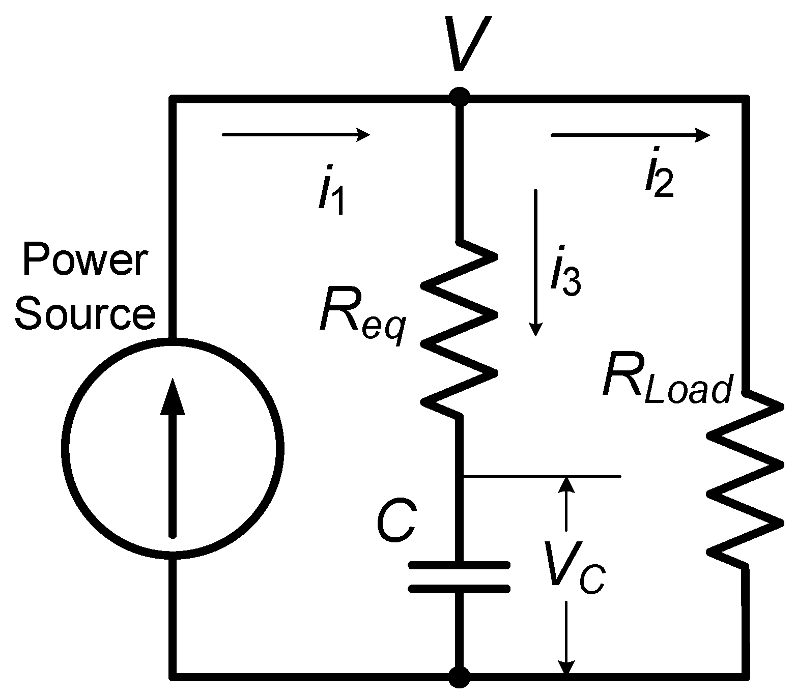
2. Rigorous Determination of SCES Capacitance Value

Selecting UC capacitance can be done according to the required time constant of the low-pass filter. For that reason, the equivalent circuit (Figure 1) of the distributing system is represented. Considering the closeness of small PV facilities to the consumers the inductive reactance of a distributing line from a high-voltage (HV) to the middle-voltage transformer was neglected. A low-pass filter is placed on the DC side of a PV system consisting of a storage capacitance C connected in parallel to a power source (MPPT of solar panels) and to the consumer, denominated by its equivalent resistance R. In accordance with the previously carried out experiments [43] with two types of UC (one is ULTIMO Li-ion of JSR Micro Co. [44] and another one is BCAP3400 P285 K048 of MAXWELL Co. [45]) showed that their internal resistance in relatively wide voltage range is changing insignificantly. Therefore, for the equivalent circuit and governing equations it can be assumed as a constant value.
The Equation describing the sum of the currents (i1, i2 and i3) are as follows:
i 3 = i 1 i 2 ;    i 1 = P V ;    i 2 = V R i 3 = P V V R
From the other side for i3:
i 3 = C d V C d t = C d d t ( V i 3 R e q ) = C d V d t R e q C d i 3 d t R e q C d i 3 d t + i 3 = C d V d t
After differentiating i3 (1) and substituting its derivative to (2) with following transformations will give:
R e q C ( P R + V 2 R V 2 ) d V d t + P V V R = C d V d t
Or after rearrangement:
P R = [ C R + R e q C ( P R + V 2 V 2 ) ] V d V d t + V 2
Considering steady-state voltage V s s = P R and T1 = CR, T2 = CReq two time constants Equation (4) can be represented as:
[ T 1 + T 2 ( 1 + V S S 2 V 2 ) ] ( V V S S ) d ( V V S S ) d t + ( V V S S ) 2 = 1
Let: t T 1 = τ ,   T 2 T 1 = α ,   V V S S = ν so Equation (5) that describes voltage behavior, becomes dimensionless and can, as a result, give a general solution:
[ 1 + α ( 1 + 1 ν 2 ) ] ν d ν d τ + ν 2 = 1
The first condition causes the following p.u. and linear ODE
( 1 + α ) d ν d τ + ν = 1
where: α and τ are as in Equation (6) and ν = V I R , current (I) represents a maximum achievable source current.
Equation (7) is properly describing a transient process until the time t*:
t T 1 ( 1 + α ) ln ( 1 1 P I 2 R )
And until voltage V* is less than V * P I .
Further, after the moment of the time (8) a solution is prolonged in accordance with non-linear Equation (6) which hasn’t strict analytical solution. Singular scheme on PSIM software was developed for investigation specific solutions of Equation (6) (Figure 2). Transient process for an output voltage and source current at the beginning of a UC charging are shown in Figure 2.
Observation of simulation curves which describe numerical solution shows the necessity of an appropriate approximation procedure. Results of simulation are shown in Figure 3 for a voltage (a) and a current changing (b).

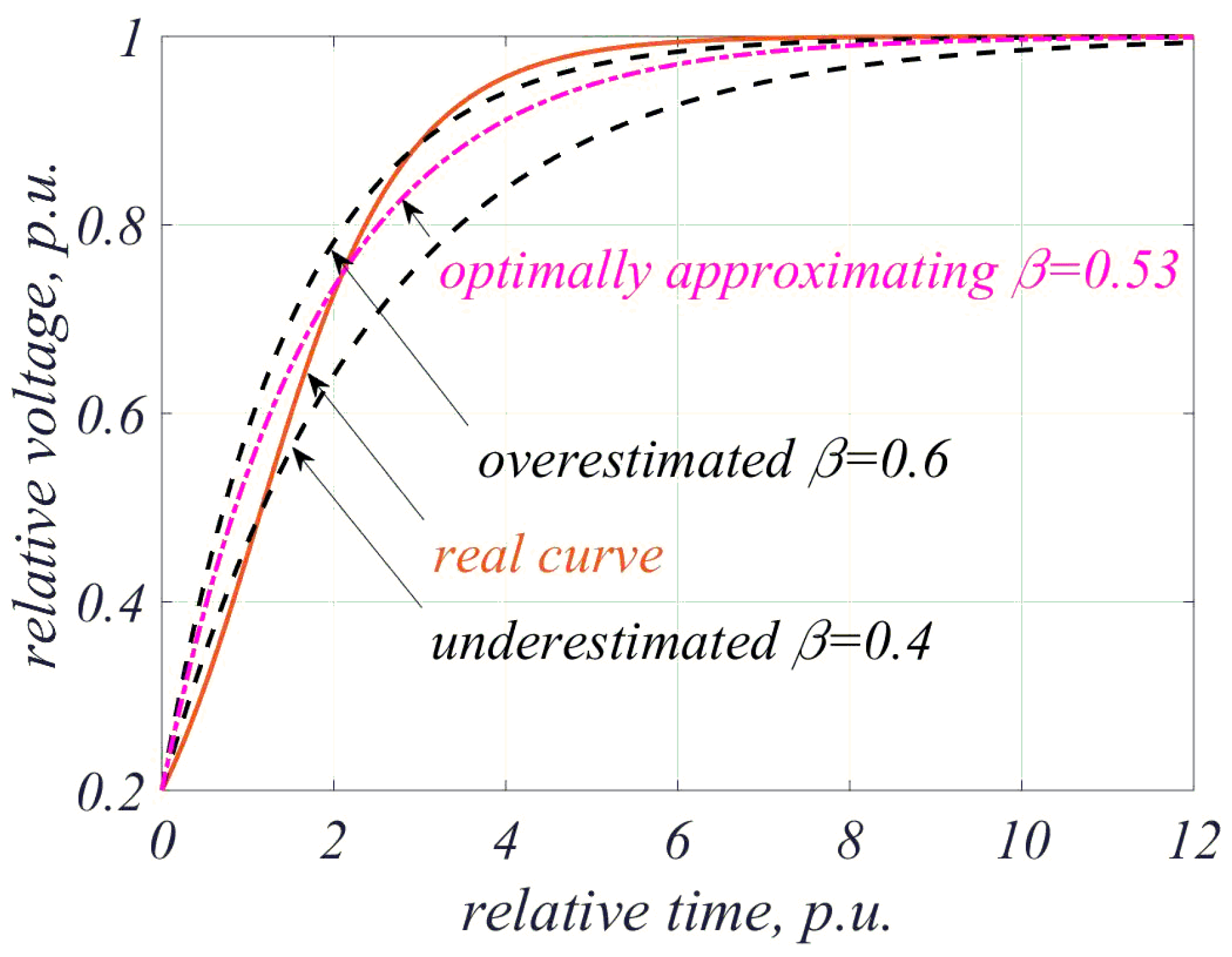
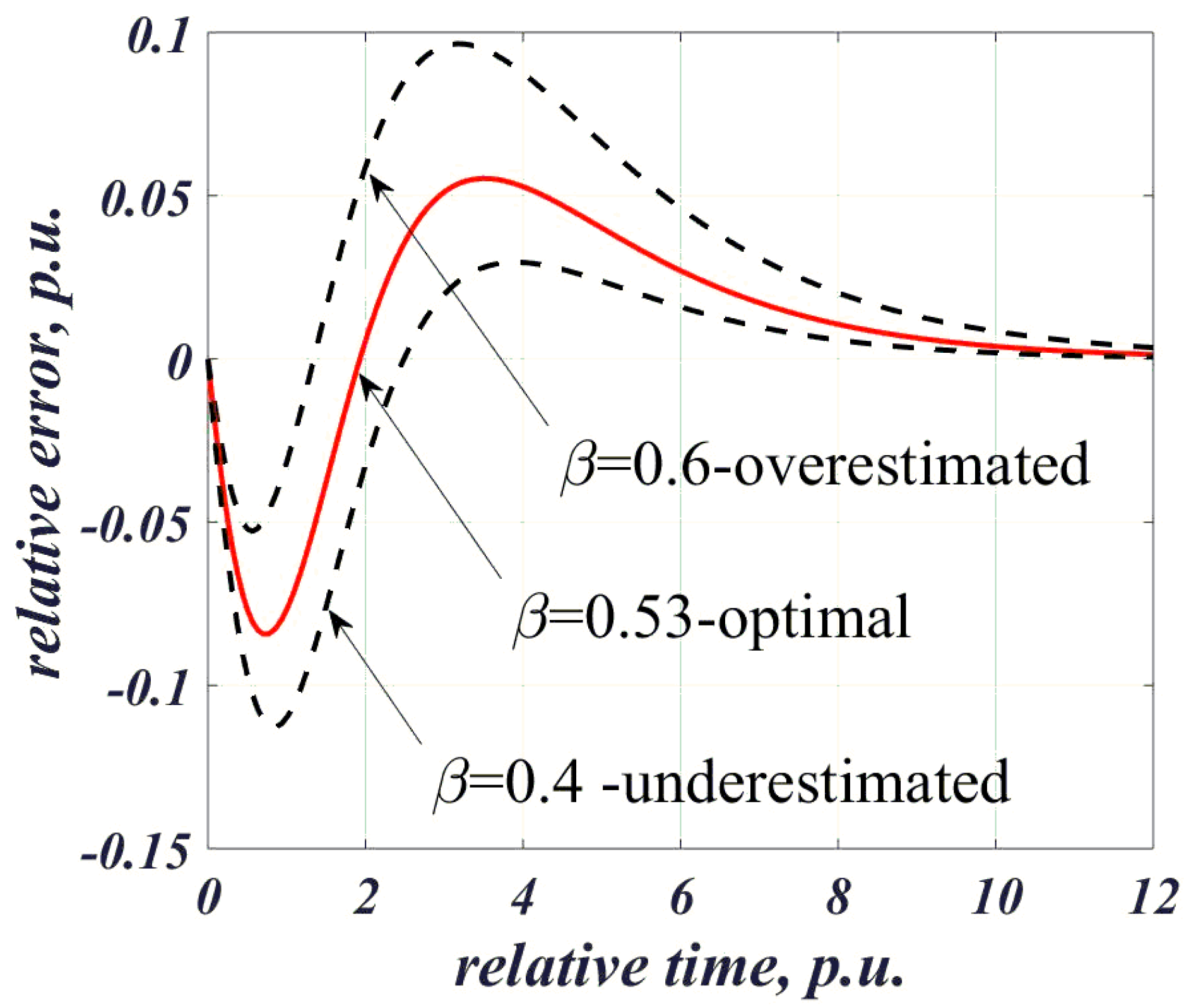
3. Approximating Procedure of a Dynamic Process

The solution of a non-linear ODE (6) is describing the dynamic process of a relative voltage ν(τ) will be considered for the approximation procedure. The approximation will be carried out by a solution of a linear ODE that will ensure at the end the application of a simple R-C circuit for this purpose. The estimation of a dynamic curve should be carried out in the usable range of UC voltage. Fair to assume out that the relative voltage ν(τ) can be provided by the inverter power lower its maximum. Considering the linear ODE for an R-C circuit, the following function for the describing of a dynamic process is:
ν ( τ ) = 1 ( 1 ν 0 ) e β τ + δ ( τ )
where: ν0 is the initial UC voltage, p.u., coefficient β represents the constants of an approximation-exponent index, δ(τ)-error function. It is easy to make sure that the error function is equal to zero when τ = 0 and τ = ∞. This circumstance is ensured by the fact that a strict solution of Equations (6) and (9) are equal in two extreme points for τ = 0 and τ = ∞. Figure 4 represents graphs of typical solutions of Equation (6): real and three additional curves showing optimal (due the meaning of Equation (10)), over- and underestimated approximations.
The goal of the approximation procedure is to choose a parameter β which will guarantee in some meaning a summarized minimum of the error function in the whole range of time. As the measure of optimization, the integral of the square of error function at τ inside [0, ∞) was chosen. That is:
S ( β , ν 0 ) = 0 δ 2 ( τ ) d τ M i n
However, we need a strict analytical procedure for a finding optimal value of parameter β. For this purpose, the expression in Equation (9) will be differentiated and then formulations of a voltage and its derivative will be substituted into the original Equation (6):
d ν d τ = β ( 1 ν 0 ) e β τ + d δ d τ
As a result, after simplification:
d δ d τ = [ 1 ( 1 ν 0 ) e β τ + δ ] [ 1 ( 1 ( 1 ν 0 ) e β τ + δ ) ] 2 1 + ( 1 + α ) [ 1 ( 1 ν 0 ) e β τ + δ ] 2 β ( 1 ν 0 ) e β τ
Only numerical solutions (different for every magnitude of parameter β and, therefore, initial voltage, ν0, can be obtained. Assuming β = 0.8 three solutions obtained by Simulink, MATLAB, for exponent β are shown in Figure 5.
It can be made sure that an optimal value of a parameter β exists, what is seen from Figure 5 showing different error curves for three β values.
The numerical procedure was applied to obtain optimal parameter β depending on initial voltage ν0 and for different coefficient α. Results can be found in Table 1.
Graphs of optimal parameter β in the range of initial voltages 0.1–0.9 and coefficient and α = 0.1; 0.05; 0.01 and 0.001 are represented in Figure 6. The relative approximation error δtot is shown in Figure 7.
Analysis of obtained data shows an appropriate exactness of a proposed approximation. The total error for an optimal coefficient β is not exceeded a reasonable value applicable for this kind of engineering problem (see Table 1 and a Figure 7).
A significant dependence of βopt from initial capacitors voltage ν0 was observed. Its magnitude varying from ~0.4 until ~0.95 for an initial voltage occupying a range from 0.1 to 0.9. Together with this, parameter α influences βopt very weakly. This circumstance can help in the development of the UC bank in real conditions. It is needed to emphasize that βopt for the linear R-C circuit is equal to one. However, in circuits fed by power (instead of voltage) sources and, therefore, having a non-linear description, βopt may be much lower and for initial voltage ν0 = 0.1–0.2 (which is quite practical), its value ~0.5. This means a very important result designating the possibility to design UC low-pass filtering (LPF) with smaller capacitance compare to the similar LPF in linear circuits with voltage sources. However, it is rather correct for low initial voltages. Coefficient βopt is growing up with the increase of an initial voltage and it is reaching the same magnitude as it occurs in linear circuits.
It should be remembering that parameter α represents a relation between T1/T2, that is Req divided by RL. On the other words, it is nothing more than the ratio between power losses in internal resistance of the UC bank versus a significant portion of a summarized loads power connected to the grid with UC storage. This ratio must be kept low and the level ~0.04–0.05 seems to be maximumly reasonable for practical application. For total loads having 1–2 MW of power and more, coefficient α should be diminished until 0.01–0.001.

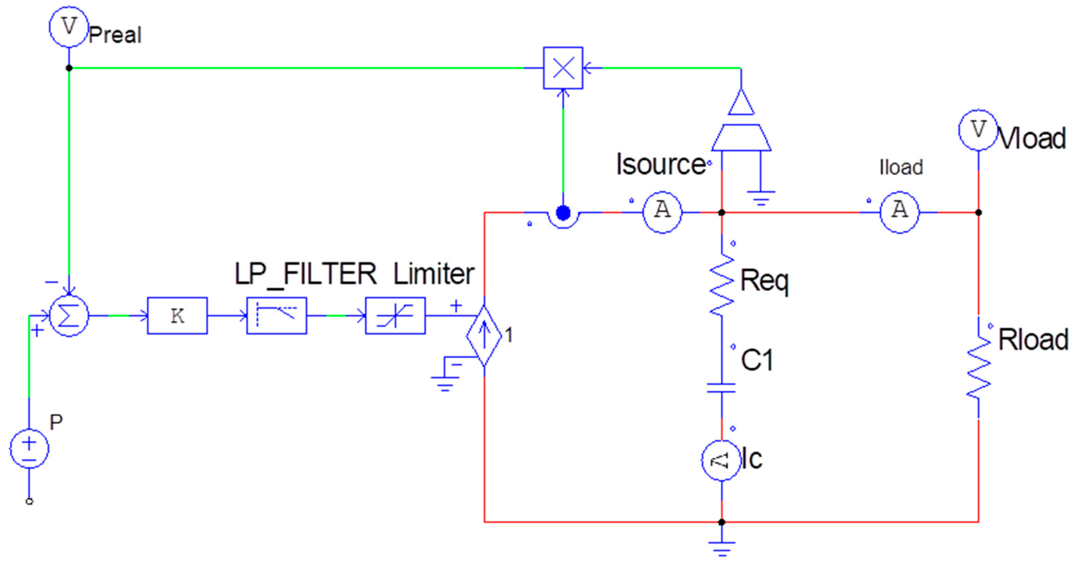
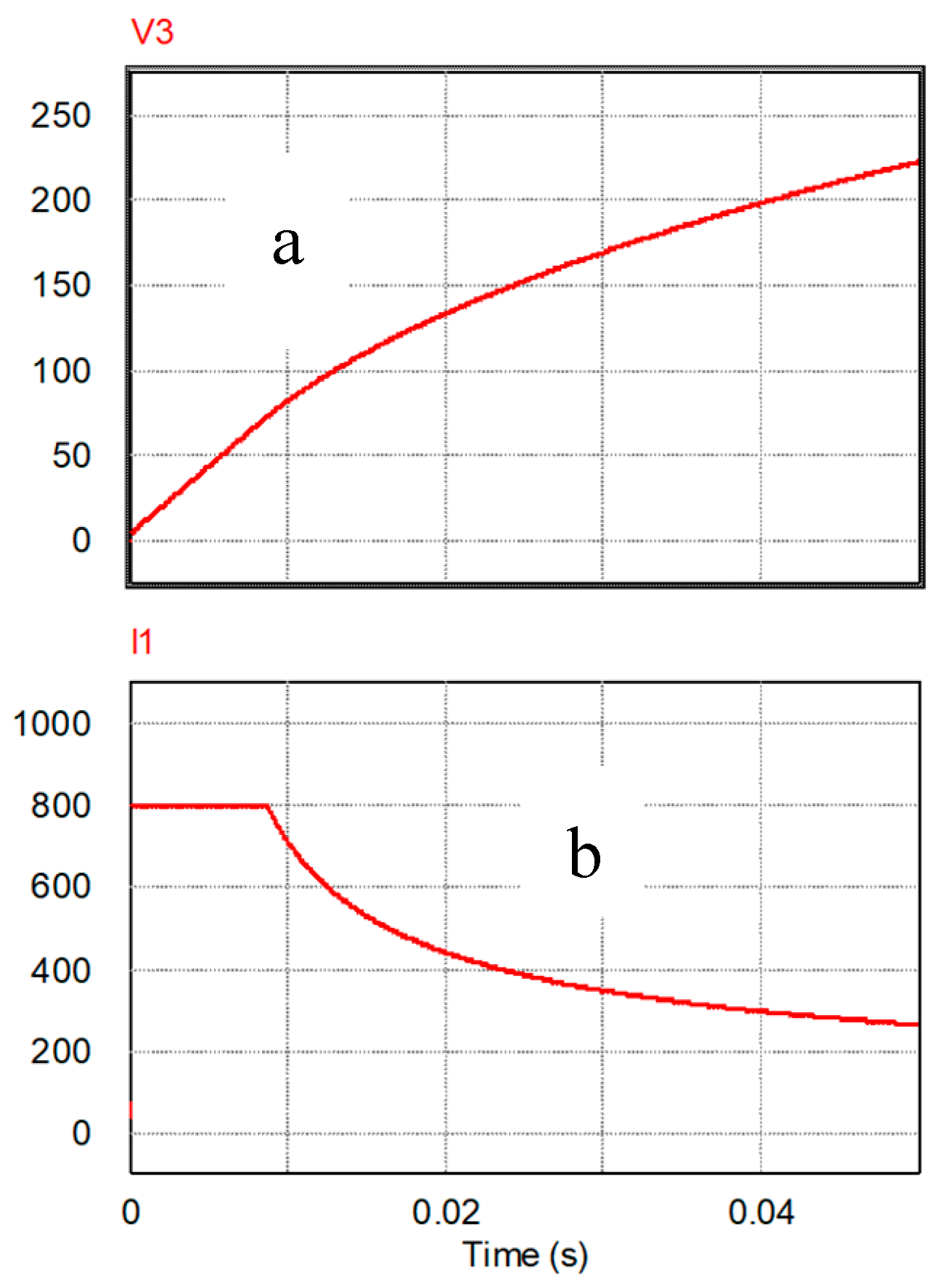
4. Practical Evaluation of a Developed Approximating Procedure

Let us consider two examples of UC bank storage to be used in a grid having 400 V line voltage, 50 Hz. Average powers of loads and of PV station are equal to 500 kW and 50 kW accordingly. The requirement for a time constant of LPF with a designed UC bank is 120 s. UC bank should be based on ULTIMO 3300F LR lithium ion capacitor prismatic cells [44] (brief technical data: Vmax = 3.8V, Vmin = 2.2V, C = 3300F, equivalent serial resistance (ESR) = 1 mΩ, M = 350 g). The voltage of a UC bank is 250 V.
For the connecting UC bank with a grid two inverters will be used: AC–DC and DC–AC both with an averaged efficiency 92%. Equivalent load resistance:
( R L ) t o t = η T V C B 2 P L = 0.92 ( 250 V ) 2 500 10 3 W = 0.115 , Ω
where: PL—real active AC load power, VCB—capacitor bank voltage, ηT—efficiency of DC/AC inverter.
Owing to the common supply of a load by a grid and PV station the load resistance, which should be considered for a power source of PV station is:
R L = ( R L ) t o t P L P P V = ( 0.115 Ω ) 500 k W 50 k W = 1.55 , Ω
Considering maximum and minimum allowable UC cell voltages, relative initial voltage is:
ν 0 = 2.2 V 3.8 V 0.58
Since coefficient β weakly depend on coefficient α, will select its value between 0.0001 and 0.01. Therefore, by the interpolation (Table 1) coefficient β value is being selected as 0.82. The required capacitance of UC will be estimated due to:
C U C = β T 1 R L = 0.82 ( 120 s ) ( 1.15 Ω ) 85.6 ,   F
UC bank should be assembled by serially connected cells [44], which number is equal to:
N U C = V C B V max = 250 V 3.8 V 66   i t e m s
A summarized capacitance and a resistance of this UC bank:
C t o t = C c e l l N U C = 3300 F 66 = 50 F R t o t = r c e l l N U C = ( 1 m Ω ) 66 = 66 m Ω = 0.066 Ω α = R t o t R L = 0.066 Ω 1.15 Ω = 0.057
Comparison of results between (17) and (15) shows a need to multiply in a bank the number of parallels connected UC arrays each having 66 cells. Enough quantity of such strings to be equal two or three. The exact choice is dictated by economical requirements. We suggest in this case to take for sure three parallel connected arrays. The total amount of cells will be equal 198, weight ~69–70 kg plus wires, cables and terminals ~3–4 kg.
Another type of UC cells, DuraBlue (Maxwell Technologies) [45] was chosen for assessment. Technical data of a K2 3400 cell: Vmax = 2.75 V, Vmin = 0 V, C = 3400 F, ESR = 0.28 mΩ, M = 510 g.
Following previously established procedure:
ν 0 = 0.1 V 2.85 V 0.1
Therefore, coefficient β < 0.40. The total required capacitance will be:
C U C < 0.40 ( 120 s ) ( 1.15 Ω ) 41.7 ,   F
As a result, the number of cells, total capacitance of a required array, its total resistance and a coefficient α are:
N U C = V C B V max = 250 V 2.85 V 88 i t e m s C t o t = C c e l l N U C = 3400 88 38.6 F R t o t = r c e l l N U C = ( 0.28 m Ω ) 88 25 m Ω = 0.025 Ω α = R t o t R L = 0.025 Ω 1.15 Ω = 0.022
Comparison of the results from Equations (20) and (21) allows making the conclusion about the need to include two arrays of DuraBlue 3400F 2.85 V [45] cells each with 88 items. The total cell number would be equal to 176, with a weight of 89–90 kg plus wires, cables, and terminals ~3–4 kg.

5. Results and Conclusions

A method for estimation capacitance values of UC in low-pass filtering circuit aiming to flatten deviation of a power source such as PV power facilities located near or inside existing townships and villages was submitted.
This method is based on the analysis of an equivalent circuit reflected to the DC side of a UC storage. Owing to the vicinity of consumers to PV and UC storage, equivalent circuit includes distribution transformer and a connecting line as a voltage source, PV facilities as a power source, UC storage as a capacitance having internal resistance and consumers as an equivalent resistance.
The dynamic process in this network is described a non-linear ODE that prevent a usage of well-established analytical solutions knowing for linear circuits.
It was shown that a non-linear solution can be represented by an appropriate linear ODE which can adequately describe the parameters of a non-linear circuit.
Should be emphasized that optimal exponent index in the approximating expression strongly dependent on an initial UC voltage. Its value is varying more than two times in the magnitude obtaining minimum for low initial voltages.
In contrast to the powerful influence of an initial voltage, a ratio between internal resistance of UC bank and an equivalent load resistance has a much lower effect, which could be neglected in some cases.
Submitted approach significantly improve the accuracy of filtering design aiming for leveling power flows from power source to the load.
The procedure for develop LPF was applied showing principle possibility to use this method in real practical situation for electrical grids having massive involvement of PV power plants.

Author Contributions

O.S. developed the math model and managed preparation of the manuscript. E.F. participated in the math equations and solutions. M.A. provided the idea of the research and collaborated in math solution verification.

Funding

This research received no external funding.

Conflicts of Interest

The authors declare no conflict no interest.

References

  1. Piano, S.L.; Mayumi, K. Toward an integrated assessment of the performance of photovoltaic power stations for electricity generation. Appl. Energy 2017, 186, 167–174. [Google Scholar] [CrossRef]
  2. Raugei, M.; Sgouridis, S.; Murphy, D.; Fthenakis, V.; Frischknecht, R.; Breyer, C.; Bardi, U.; Barnhart, C.; Buckley, A.; Carbajales-Dale, M. Energy return on energy invested (ERoEI) for photovoltaic solar systems in regions of moderate insolation: A comprehensive response. Energy Policy 2017, 102, 377–384. [Google Scholar] [CrossRef]
  3. Von Appen, J.; Braun, M.; Stetz, T.; Diwold, K.; Geibel, D. Time in the sun: The challenge of high PV penetration in the German electric grid. IEEE Power Energy Mag. 2013, 11, 55–64. [Google Scholar] [CrossRef]
  4. Feilat, E.A.; Azzam, S.; Al-Salaymeh, A. Impact of large PV and wind power plants on voltage and frequency stability of Jordan’s national grid. Sustain. Cities Soc. 2018, 36, 257–271. [Google Scholar] [CrossRef]
  5. Rehman, S.; Ahmed, M.A.; Mohamed, M.H.; Al-Sulaiman, F.A. Feasibility study of the grid connected 10MW installed capacity PV power plants in Saudi Arabia. Renew. Sustain. Energy Rev. 2017, 80, 319–329. [Google Scholar] [CrossRef]
  6. Paatero, J.V.; Lund, P.D. Effects of large-scale photovoltaic power integration on electricity distribution networks. Renew. Energy 2007, 32, 216–234. [Google Scholar] [CrossRef]
  7. Haque, M.M.; Wolfs, P. A review of high PV penetrations in LV distribution networks: Present status, impacts and mitigation measures. Renew. Sustain. Energy Rev. 2016, 62, 1195–1208. [Google Scholar] [CrossRef]
  8. Averbukh, M.; Ben-Galim, Y.; Uhananov, A. Development of a quick dynamic response maximum power point tracking algorithm for off-grid system with adaptive switching (On–Off) control of dc/dc converter. J. Sol. Energy Eng. 2013, 135, 021003. [Google Scholar] [CrossRef]
  9. Gasulla, M.; Robert, F.J.; Jordana, J.; Ripoll-Vercellone, E.; Berenguer, J.; Reverter, F. A High-Efficiency RF Harvester with Maximum Power Point Tracking. Proceedings 2018, 2, 1049. [Google Scholar] [CrossRef]
  10. Karami, N.; Moubayed, N.; Outbib, R. General review and classification of different MPPT techniques. Renew. Sustain. Energy Rev. 2017, 68, 1–18. [Google Scholar] [CrossRef]
  11. Kuperman, A.; Sitbon, M.; Gadelovits, S.; Averbukh, M.; Suntio, T. Single-source multi-battery solar charger: Analysis and stability issues. Energies 2015, 8, 6427–6450. [Google Scholar] [CrossRef]
  12. Mahmoud, Y.; El-Saadany, E.F. A novel MPPT technique based on an image of PV modules. IEEE Trans.Energy Convers. 2017, 32, 213–221. [Google Scholar] [CrossRef]
  13. Metry, M.; Shadmand, M.B.; Balog, R.S.; Abu-Rub, H. MPPT of photovoltaic systems using sensorless current-based model predictive control. IEEE Trans. Ind. Appl. 2017, 53, 1157–1167. [Google Scholar] [CrossRef]
  14. Mohanty, S.; Subudhi, B.; Ray, P.K. A grey wolf-assisted perturb & observe MPPT algorithm for a PV system. IEEE Trans. Energy Convers. 2017, 32, 340–347. [Google Scholar]
  15. Sundareswaran, K.; Vigneshkumar, V.; Sankar, P.; Simon, S.P.; Nayak, P.S.R.; Palani, S. Development of an improved P&O algorithm assisted through a colony of foraging ants for MPPT in PV system. IEEE Trans. Ind. Inform. 2016, 12, 187–200. [Google Scholar]
  16. Tajuddin, M.; Arif, M.; Ayob, S.; Salam, Z. Perturbative methods for maximum power point tracking (MPPT) of photovoltaic (PV) systems: A review. Int. J. Energy Res. 2015, 39, 1153–1178. [Google Scholar] [CrossRef]
  17. Viloria-Porto, J.; Robles-Algarín, C.; Restrepo-Leal, D. A novel approach for an MPPT controller based on the ADALINE network trained with the RTRL algorithm. Energies 2018, 11, 3407. [Google Scholar] [CrossRef]
  18. Wang, Y.; Yang, Y.; Fang, G.; Zhang, B.; Wen, H.; Tang, H.; Fu, L.; Chen, X. An advanced maximum power point tracking method for photovoltaic systems by using variable universe fuzzy logic control considering temperature variability. Electronics 2018, 7, 355. [Google Scholar] [CrossRef]
  19. Chaudhary, P.; Rizwan, M. Voltage regulation mitigation techniques in distribution system with high PV penetration: A review. Renew. Sustain. Energy Rev. 2018, 82, 3279–3287. [Google Scholar] [CrossRef]
  20. Azzouz, M.A.; Farag, H.E.; El-Saadany, E.F. Real-time fuzzy voltage regulation for distribution networks incorporating high penetration of renewable sources. IEEE Syst. J. 2017, 11, 1702–1711. [Google Scholar] [CrossRef]
  21. Chen, J.; Zhu, R.; Liu, M.; de Carne, G.; Liserre, M.; Milano, F.; O’Donnell, T. Smart transformer for the provision of coordinated voltage and frequency support in the grid. In Proceedings of the IECON 2018-44th Annual Conference of the IEEE Industrial Electronics Society, Washington, DC, USA, 21–23 October 2018; pp. 5574–5579. [Google Scholar]
  22. Deng, J.; Zhang, G.; Geng, Y.; Wang, J. Design of intelligent on-load tap changer controlled by permanent magnetic actuator. In Proceedings of the 2017 1st International Conference on Electrical Materials and Power Equipment (ICEMPE), Xi’an, China, 14–17 May 2017; pp. 270–274. [Google Scholar]
  23. Gomez-Exposito, A.; Conejo, A.J.; Canizares, C. Electric Energy Systems: Analysis and Operation; CRC Press: Boca Raton, FL, USA, 2018. [Google Scholar]
  24. Korpikiewicz, J.G.; Mysiak, P. Classical and solid-state tap-changers of HV/MV regulating transformers and their regulators. Acta Energetica 2017. [Google Scholar] [CrossRef]
  25. Rauma, K.; Cadoux, F.; Roupioz, G.; Dufournet, A.; Hadj-Said, N. Optimal location of voltage sensors in low voltage networks for on-load tap changer application. IET Gener. Transm. Distrib. 2017, 11, 3756–3764. [Google Scholar] [CrossRef]
  26. Song, I.; Jung, W.; Chu, C.; Cho, S.; Kang, H.; Choi, J. General and simple decision method for DG penetration level in view of voltage regulation at distribution substation transformers. Energies 2013, 6, 4786–4798. [Google Scholar] [CrossRef]
  27. De Oliveira Quevedo, J.; Cazakevicius, E.; Beltrame, R.C.; Marchesan, T.B.; Michels, L.; Rech, C.; Schuch, L. Analysis and design of an electronic on-load tap changer distribution transformer for automatic voltage regulation. IEEE Trans. Ind. Electron. 2017, 64, 883–894. [Google Scholar] [CrossRef]
  28. Fernández, S.M.; García, S.M.; Olay, C.C.; Rodríguez, J.C.C.; García, R.V.; López, J.V. Electronic tap changer for very high-power medium-voltage lines with no Series–Parallel thyristors. IEEE Trans. Ind. Electron. 2018, 65, 5237–5249. [Google Scholar] [CrossRef]
  29. Jin, G.; Yang, K.; Liu, J. Design of a novel voltage regulating distribution transformer with a power electronic-assisted booster system. J. Eng. 2017, 2017, 2324–2327. [Google Scholar] [CrossRef]
  30. Lu, K.; Lin, F.; Yang, B. Profit optimization-based power compensation control strategy for grid-connected PV system. IEEE Syst. J. 2018, 12, 2878–2881. [Google Scholar] [CrossRef]
  31. Rostami, A.; Olamaei, J.; Rostami, H. A new islanding detection method in micro grids based on applying full electronic tap changer in power transformer. Electron. Eng. Lett. 2017, 1. [Google Scholar]
  32. Ma, H.; Gu, S.; Wang, H.; Xu, H.; Wang, C.; Zhou, H. On-load automatic voltage regulation system designed via thyristor for distribution transformer. In Proceedings of the 2017 20th International Conference on Electrical Machines and Systems (ICEMS), Sydney, NSW, Australia, 11–14 August 2017; pp. 1–5. [Google Scholar]
  33. Xu, X.; Wang, Y.; Zhao, T. A Hybrid Switch based Arcless Voltage Regulator. In Proceedings of the 2018 9th IEEE International Symposium on Power Electronics for Distributed Generation Systems (PEDG), Charlotte, NC, USA, 25–28 June 2018; pp. 1–5. [Google Scholar]
  34. Hashemi, S.; Østergaard, J. Methods and strategies for overvoltage prevention in low voltage distribution systems with PV. IET Renew. Power Gener. 2016, 11, 205–214. [Google Scholar] [CrossRef]
  35. Mateo, C.; Frías, P.; Cossent, R.; Sonvilla, P.; Barth, B. Overcoming the barriers that hamper a large-scale integration of solar photovoltaic power generation in European distribution grids. Sol. Energy 2017, 153, 574–583. [Google Scholar] [CrossRef]
  36. Luthander, R.; Lingfors, D.; Widén, J. Large-scale integration of photovoltaic power in a distribution grid using power curtailment and energy storage. Sol. Energy 2017, 155, 1319–1325. [Google Scholar] [CrossRef]
  37. Marra, F.; Yang, G.; Træholt, C.; Ostergaard, J.; Larsen, E. A decentralized storage strategy for residential feeders with photovoltaics. IEEE Trans. Smart Grid 2014, 5, 974–981. [Google Scholar] [CrossRef]
  38. Chen, S.X.; Gooi, H.B.; Wang, M.Q. Sizing of energy storage for microgrids. IEEE Trans. Smart Grid 2012, 3, 142–151. [Google Scholar] [CrossRef]
  39. Yang, Y.; Li, H.; Aichhorn, A.; Zheng, J.; Greenleaf, M. Sizing strategy of distributed battery storage system with high penetration of photovoltaic for voltage regulation and peak load shaving. IEEE Trans. Smart Grid 2014, 5, 982–991. [Google Scholar] [CrossRef]
  40. Glavin, M.E.; Hurley, W.G. Optimization of a photovoltaic battery ultracapacitor hybrid energy storage system. Sol. Energy 2012, 86, 3009–3020. [Google Scholar] [CrossRef]
  41. Samosir, A.S.; Yatim, A.H.M. Implementation of dynamic evolution control of bidirectional DC-DC converter for interfacing ultracapacitor energy storage to fuel-cell system. IEEE Trans. Ind. Electron. 2010, 57, 3468–3473. [Google Scholar] [CrossRef]
  42. Wang, L.; Vo, Q.; Prokhorov, A.V. Dynamic stability analysis of a hybrid wave and photovoltaic power generation system integrated into a distribution power grid. IEEE Trans. Sustain. Energy 2017, 8, 404–413. [Google Scholar] [CrossRef]
  43. Yahalom, A.; Abitbul, Y.; Averbukh, M. Preliminary Dynamic Parameters Comparison of Asymmetric (Ultimo CPQ 2300S, JSR Co.) and Double-Layer (BCAP3400, Maxwell Co.) Ultracapacitors. In Proceedings of the 2018 IEEE International Conference on the Science of Electrical Engineering in Israel (ICSEE), Eilat, Israel, 12–14 December 2018; pp. 1–4. [Google Scholar]
  44. Available online: https://www.jsrmicro.be/emerging-technologies/lithium-ion-capacitor/products/ultimo-lithium-ion-capacitor-prismatic-cells (accessed on 1 March 2018).
  45. Available online: http://www.maxwell.com/images/documents/K2_2_85V_DS_3000619EN_3_.pdf (accessed on 3 July 2018).
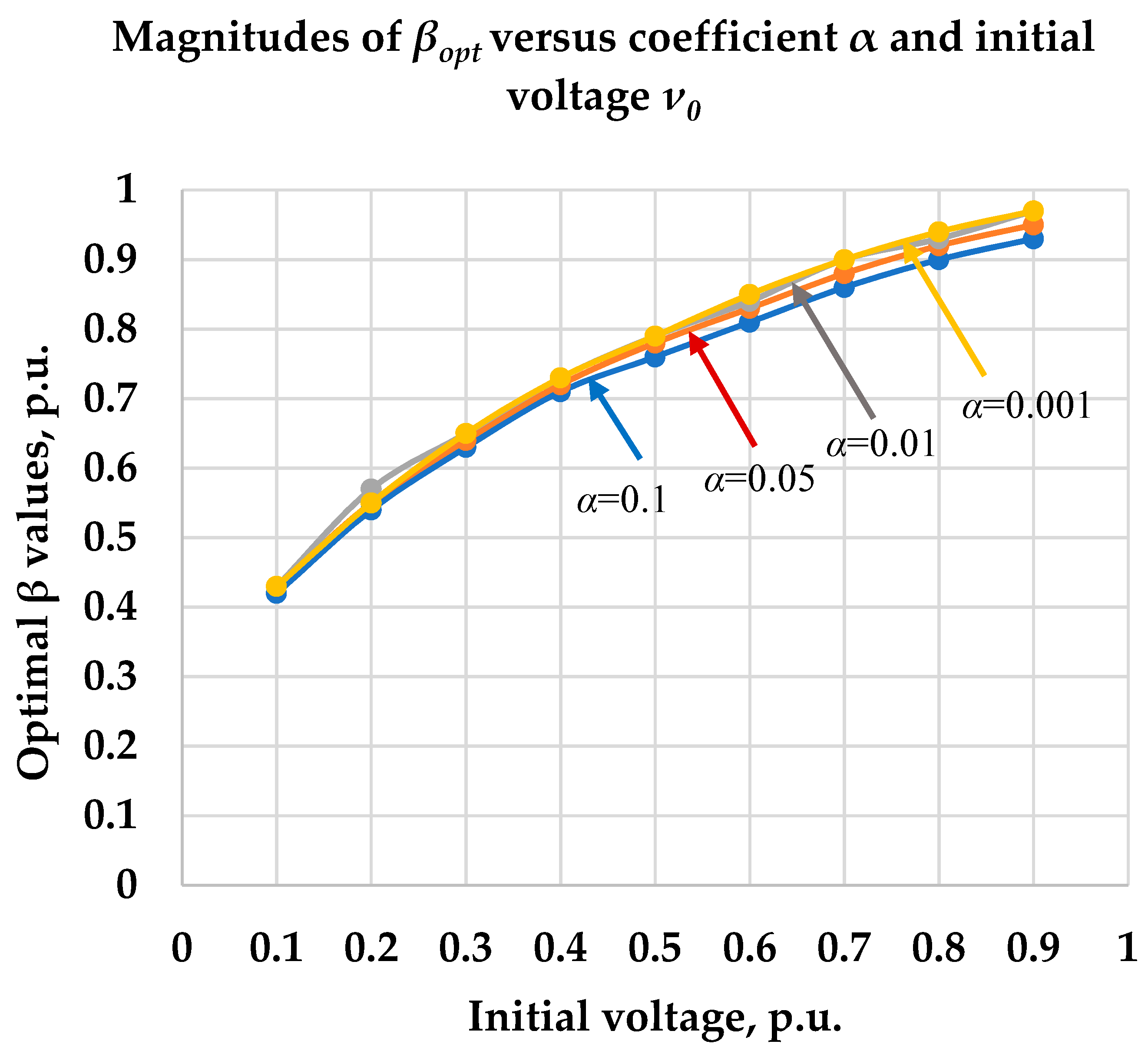
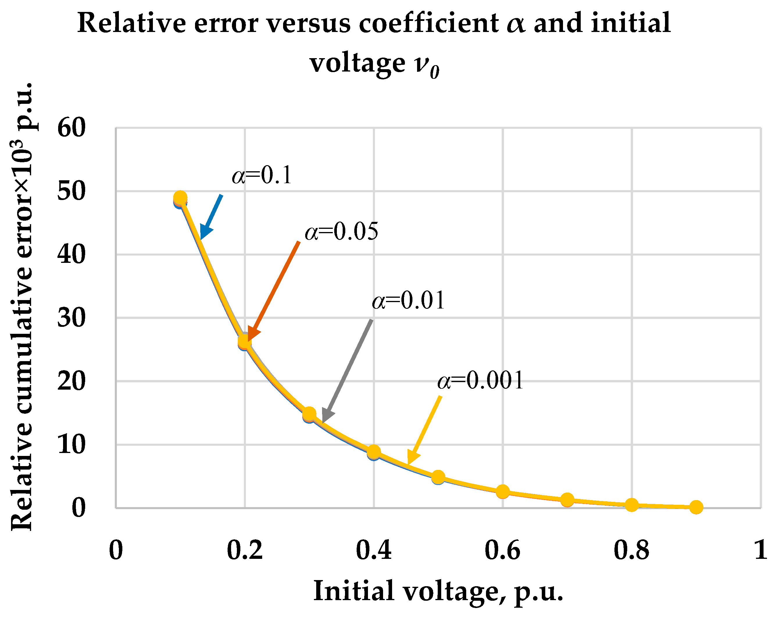
Figure 1. Equivalent circuit of the distributing network.
Electronics 08 00357 g001
Figure 2. Simulating PSIM scheme for representation transient process in R-(RC) circuit.
Electronics 08 00357 g002
Figure 3. Results of a simulating of a transient process in R-(RC) circuit: (a) voltage rise; (b) current changing.
Electronics 08 00357 g003
Figure 4. Voltage curves of a real dynamic process and its approximations: optimal β = 0.53, overestimated β = 0.60, and underestimated β = 0.53, β = 0.40.
Electronics 08 00357 g004
Figure 5. Relative error function δ(τ) for three values of parameter β causing to under-, over-, and optimal approximation for ν0 = 0.7 and α = 0.05.
Electronics 08 00357 g005
Figure 6. Optimal coefficient β values in RC-R circuit with the supply of a constant power source versus initial capacitor voltage.
Electronics 08 00357 g006
Figure 7. Weighted average quadratic error of an approximation procedure versus initial voltage and for different coefficient α.
Electronics 08 00357 g007
Table 1. Optimal values of the coefficient β.
Vo0.10.20.30.40.50.60.70.80.9
α = 0.1(βopt)abs0.420.540.630.710.760.810.860.90.93
(δtot, p.u.) × 10348.225.814.48.54.72.51.20.450.11
α = 0.05 (βopt)abs0.430.550.640.720.780.830.880.920.95
(δtot, p.u.) × 10348.62614.68.74.82.51.20.460.1
α = 0.01(βopt)abs0.430.570.650.730.790.840.90.930.97
(δtot, p.u.) × 10348.926.714.88.84.82.61.30.460.11
α = 0.001(βopt)abs0.430.550.650.730.790.850.90.940.97
(δtot, p.u.) × 1034926.314.98.94.92.61.30.470.12

