Article

Wideband Printed Wide-Slot Antenna with Fork-Shaped Stub

State Key Laboratory of Space-Ground Integrated Information Technology, Beijing Institute of Satellite Information Engineering, Beijing 100095, China
*
Author to whom correspondence should be addressed.
Electronics 2019, 8(3), 347; https://doi.org/10.3390/electronics8030347
Submission received: 1 March 2019 / Revised: 14 March 2019 / Accepted: 18 March 2019 / Published: 21 March 2019
(This article belongs to the Section Microwave and Wireless Communications)

Abstract

:
This paper presents a multiple-resonance technique that sought to achieve a wide bandwidth for printed wide-slot antennas with fork-shaped stubs. By properly appending an extra fork-shaped stub onto the main fork-shaped stub, the impedance bandwidth was able to be clearly broadened. To validate this technique, two designs where the extra stubs were added at different positions of the main stub were constructed. The measured impedance bandwidths of the proposed antennas reached 148.6% (0.9–6.1 GHz) for S11 < −10 dB, indicating a 17.9% wider bandwidth than that of the normal antenna (0.9–4.3 GHz). Moreover, a stable radiation pattern was observed within the operating frequency range. The proposed antennas were confirmed to be much-improved candidates for applications in various wireless communication systems.

1. Introduction

With the development of wireless communication systems, the demand for wideband and multiband antennas with omnidirectional coverage, simple structure and easy integration keeps increasing. Recently, wideband antennas for communication applications have attracted a great deal of attention from researchers [1,2,3].
Among the planar wideband antennas, the printed slot antenna is one of the most promising candidates for wideband applications due to its merits of wide bandwidth (BW), low profile, light weight, ease of fabrication and integration with other devices [3]. In contrast to conventional narrow-slot antennas, wide-slot (WS) antennas show much better wideband characteristics [4]. Printed WS antennas are generally composed of a WS radiator etched on the ground plane, a microstrip line or coplanar waveguide (CPW) feeding structure, and a tuning stub.
In recent years, various WS antennas with different slot and tuning stub shapes have been reported. BW enhancement techniques, which are the main focus of these slot antenna designs, can be categorized into three kinds. The first kind manipulates the field distribution in the slot by changing the shape of the slot [4,5,6,7,8,9,10,11], for example by adding small resonant slots to the corners of the main slot [4,5], inserting periodic open-end stubs in the aperture [8], or adding a hexagonal slot on the ground plane [9], to enhance the wideband matching. The second kind of technique embeds parasitic elements on the ground plane or along the feed line [12,13,14], for example by inserting an inverted T-shaped and rotated C-shaped conductor-backed plane into the slot [13], thus adjusting the coupling levels of several resonances. The third kind of technique slots or add extra stubs to the radiating patch [15,16,17], for example by inserting a pair of L-shaped slits into the square radiating patch [17]. Currently, some new approaches have been presented to improve the impedance BW. In [18], a WS antenna with a C-shaped slot and sword-shaped tuning stub is proposed. In [19], a CPW-fed WS antenna with an E-shaped tuning stub and a hexagonal patch is proposed and optimized.
The method presented in this paper can be classified as the third kind mentioned above, but it is different from the previous literature, which generally made modifications on a rectangular or circular patch. In this paper, the multi-branch method is applied to a fork-shaped stub. In [20], a printed WS antenna with a fork-shaped tuning stub was proposed and showed good BW enhancement, with an impedance BW of 46.48% for VSWR < 1.5 (S11 < −14 dB). By recalculating this with the parameters provided in [20], it was found that the impedance BW for S11 < −10 dB was 85.4%. This approach has caused significant progress in BW enhancement and has attracted the attention of many researchers. In [21], a rectangular slot antenna with a fork-shaped stub excited by CPW obtained an impedance BW of 110% for S11 < −10 dB. In [22], a printed elliptical slot antenna using a tapered microstrip feeding line with a fork-shaped tuning stub achieved an impedance BW of 117% for S11 < −10 dB. In [23], a printed WS antenna with a centered rectangular parasitic patch, fed by a fork-like tuning stub with rectangular parasitic elements is proposed, with an impedance BW of 148.4% for S11 < −10 dB. It has been demonstrated that designs using a fork-shaped stub are an effective way to obtain broadband impedance matching.
In this paper, a multiple-resonance technique is proposed to achieve a wider BW for a printed WS antenna with a fork-shaped stub. By adding an extra fork-shaped stub onto the main fork-shaped stub and rounding the rectangular corner of the stub and the rectangular slot, good impedance matching over a wide operating frequency range was realized. To validate this technique, two different antennas with stubs added at different positions of the main stub were studied. Details of the proposed antenna design and experimental results are provided and discussed.
Compared with previously reported works, the advantages of the proposed antenna can be summarized as follows:
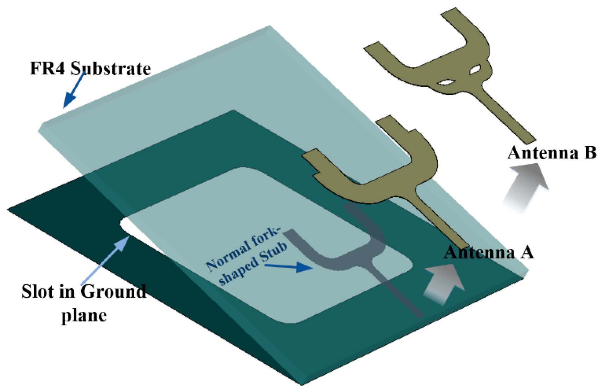
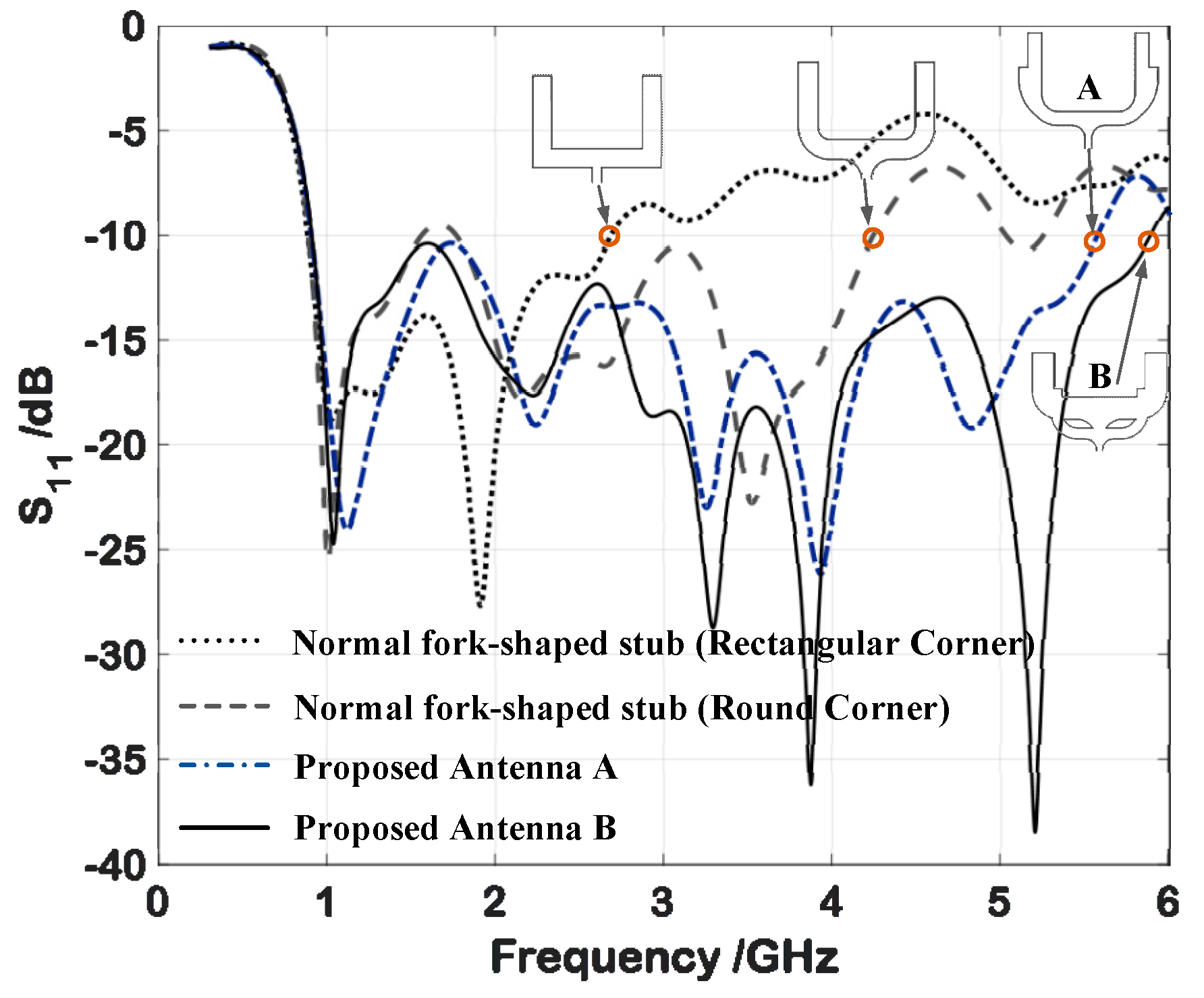
  • The proposed antenna introduces an extra resonant stub to excite additional resonant modes and provides additional tuning capabilities, resulting in a large impedance bandwidth. In contrast to the previous literature, in which the multiple-resonance technique of adding an extra resonant stub was usually applied to the rectangular or circular patch, the proposed antenna embeds an extra resonant stub into the fork-shaped stub.
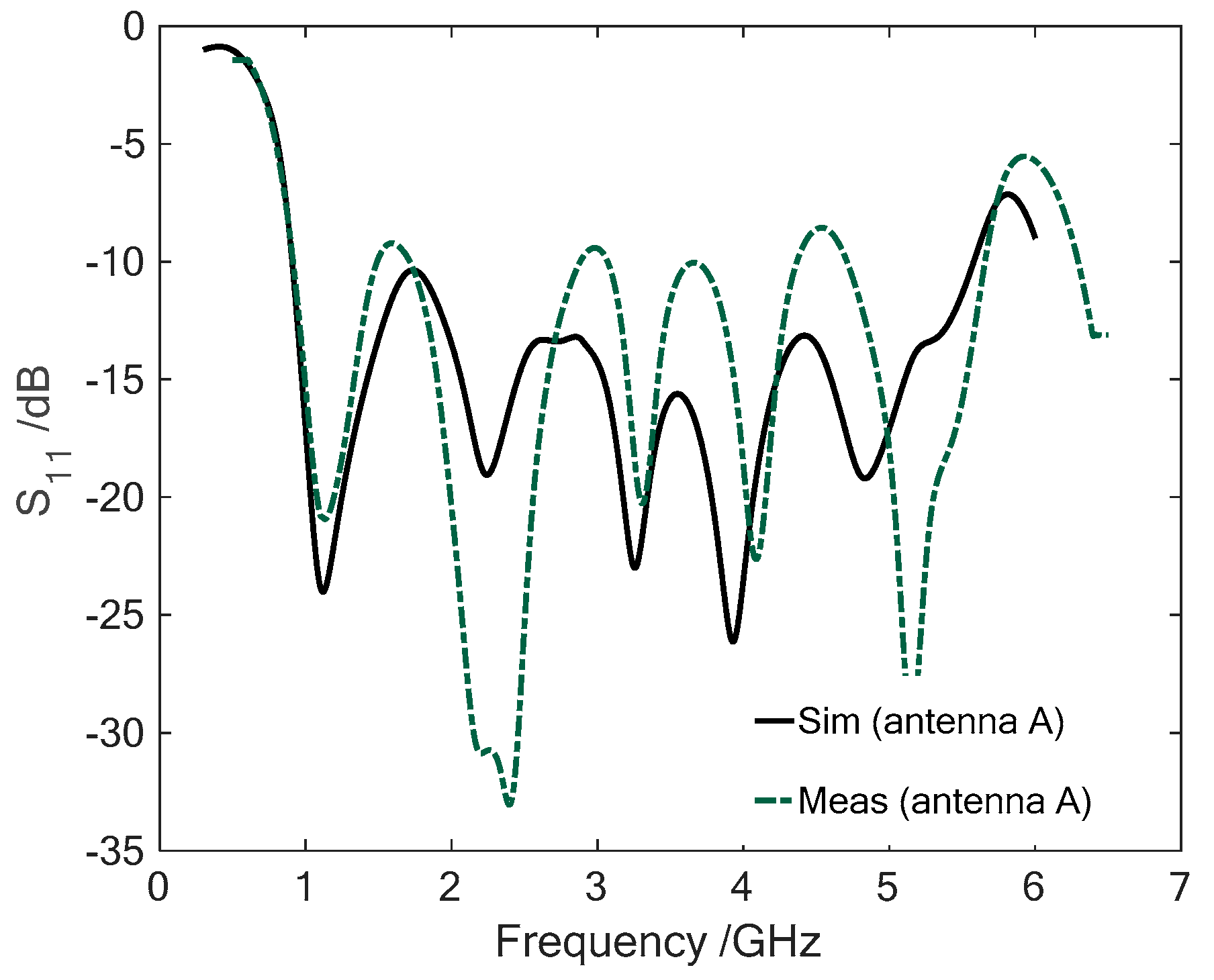
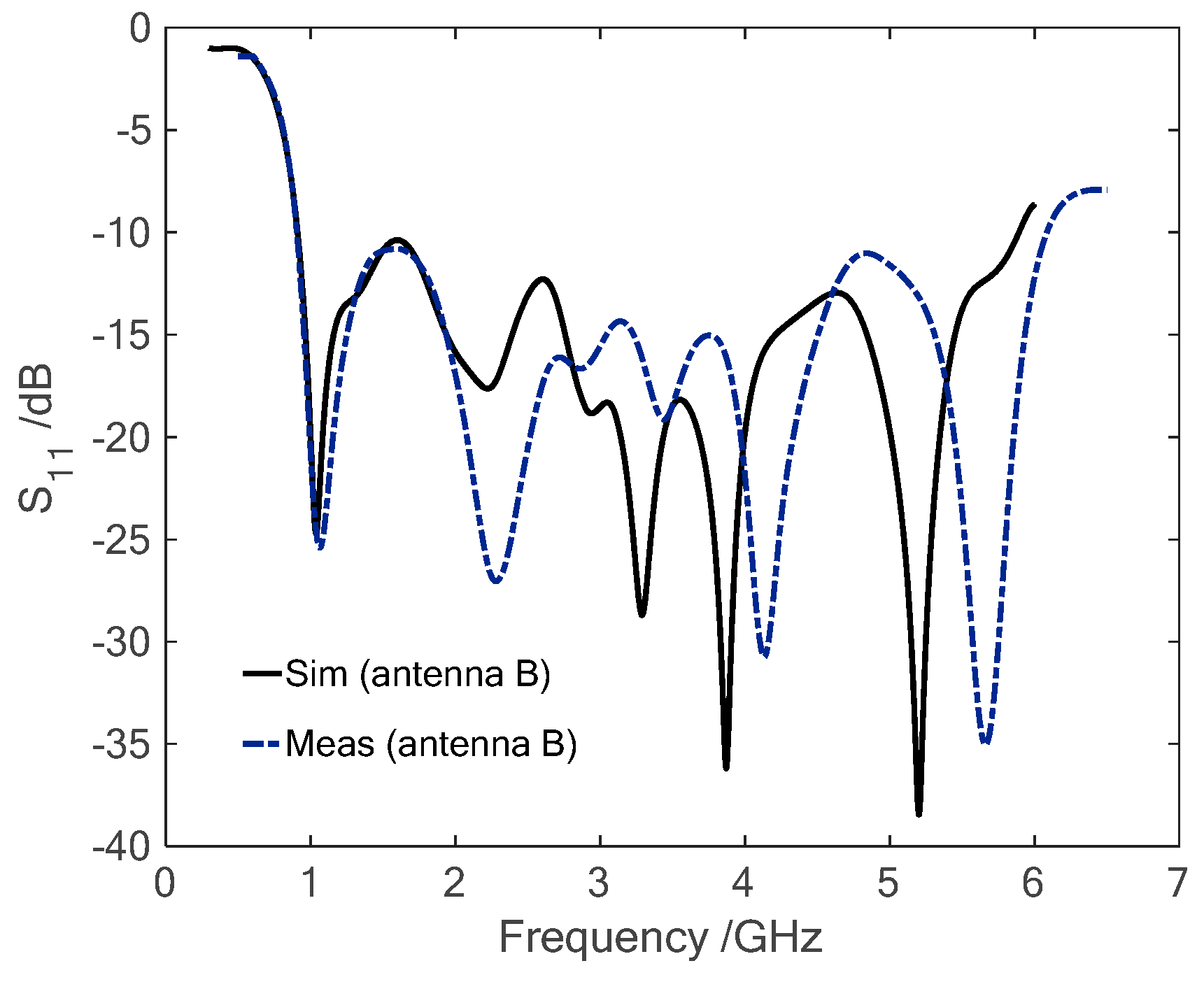
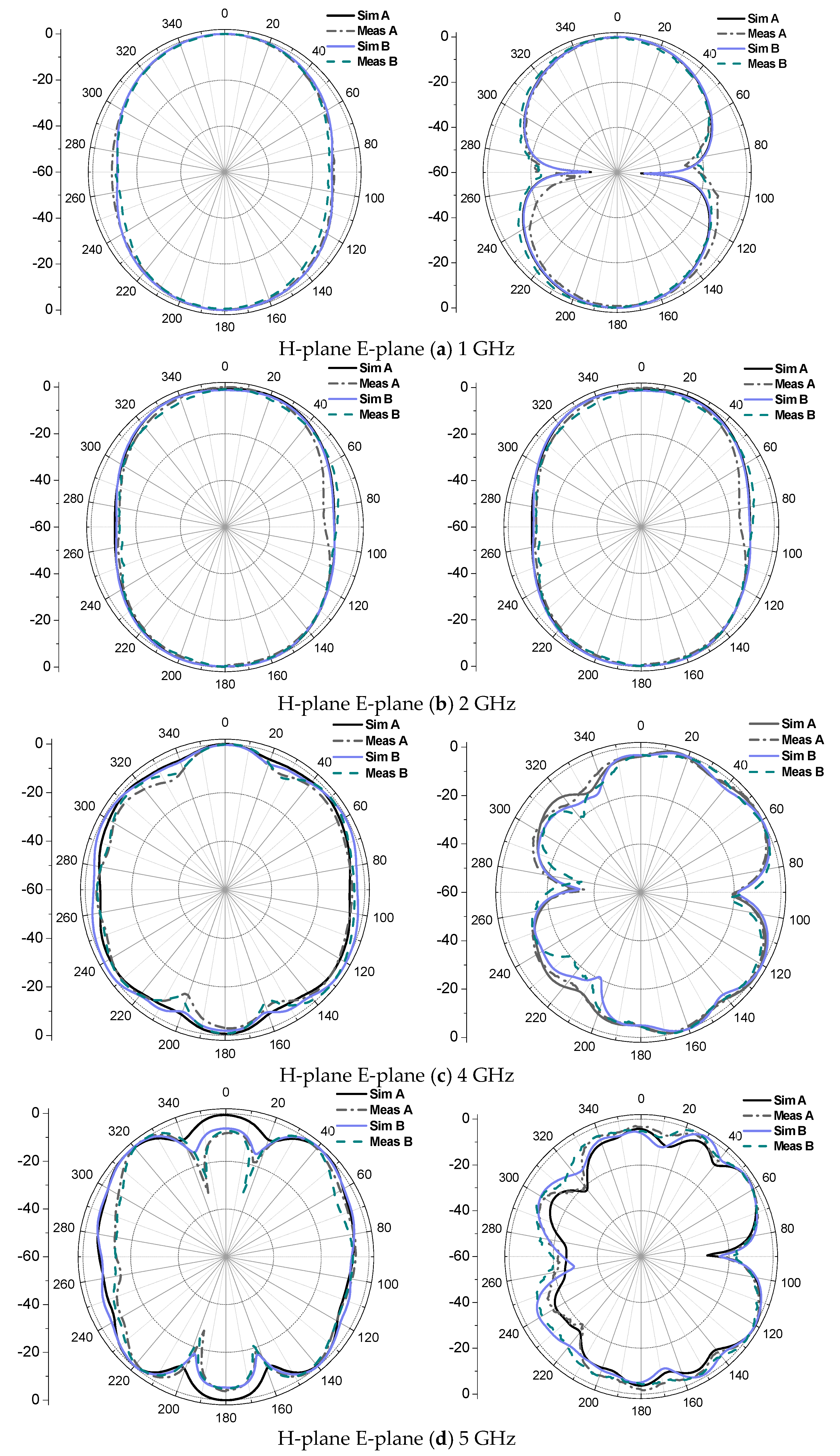
  • The measured impedance BW of the proposed antennas for S11 < −10 dB reached 148.6%, which is wider than most referenced designs. Furthermore, the proposed antenna had a stable radiation pattern in a wide BW.
  • The proposed antenna has a relatively simple geometry, which releases the computation load in the optimization process. Moreover, the added variables of the extra stub increase the tuning degrees of freedom for the impedance matching.

2. Antenna Design and Analysis

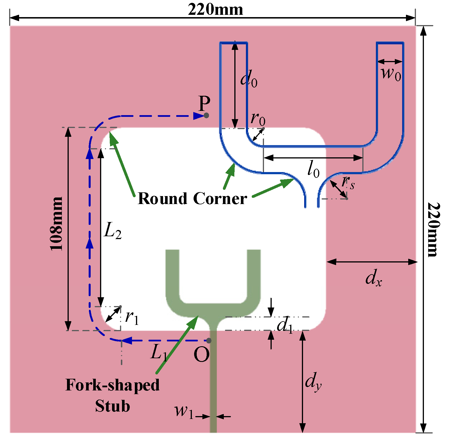
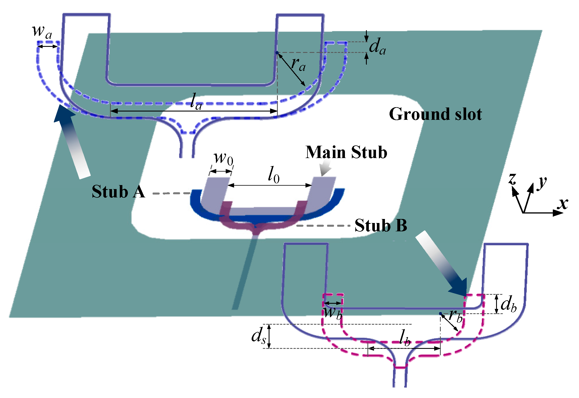
2.1. Antenna Configuration

The proposed printed WS antennas with two different tuning stubs are illustrated in Figure 1. Both of the designs were improved from the normal slot antenna with a fork-shaped stub [20]. For the normal printed WS antenna with a fork-shaped tuning stub, the slot and the feeding line were printed on different sides of the dielectric substrate.
For the comparison with the proposed antennas, a normal antenna with a fork-shaped stub was taken as a reference, as shown in Figure 2. The reference antenna was designed on a FR4 substrate, dimensions of 220 mm × 220 mm × 1.5 mm, permittivity ( ε r ) of 4.4, and a loss tangent of 0.02. The dimensions of the slot were 108 mm × 108 mm. The parameters of the normal fork-shaped stub were: l0 = 11.12 mm, w0 = 6.12 mm, d0 = 20.0 mm, r0 = 3.88 mm, rs = 6.0 mm, w1 = 3.06 mm, and d1 = 4.0 mm. Note that all the rectangular corners shown in the structure (see Figure 2) have been replaced by round corners, considering that a smooth transition contributes to better impedance matching [11].
It is well known that a half-wavelength variation in current can be observed along the boundary of the slot at the lowest resonant frequency [24]. Hence, the perimeter (p) of the slot boundary OP, which is shown by dashed lines in Figure 2, is appropriately related to the wavelength (λ1) at the lowest resonant frequency as
λ 1 / 2 = p = 2 L 1 + L 2 + π r 1
The lowest resonant frequency f L can be expressed as
f L ( GHz ) = 300 p ε e f f
with
ε e f f = ( ε r + 1 ) 2
where the unit of perimeter (p) is in millimeters. In the design, the parameters of the rectangular slot were: L1 = 44 mm, L2 = 88 mm, r1 = 10 mm, dx = 56 mm, and dy = 56 mm. It was found that the lowest resonant frequency f L was about 0.9 GHz. This will be validated in a subsequent simulation.
According to the 3GPP standard (the 3rd Generation Partnership Project), the 5G frequency range (the 5th generation mobile communication technology) at low frequency is from 450 MHz to 6 GHz. Most of its usable frequencies range from 900 MHz to 6 GHz. Although the normal WS antenna with a fork-shaped stub can obtain a wide impedance BW, it is still not enough. Therefore, to further improve the BW, a multiple-resonance technique for the printed WS antenna with a fork-shaped stub is proposed.
It has been found that incorporating multiple tuning stubs into a planar WS antenna can excite more resonant modes. However, before the effective tuning, the multiple resonant frequency bands do not overlap nor are they impedance matched. By appropriately tuning the position and dimensions of the stubs, the overlap and impedance matching of these resonances can be promoted to realize the large impedance bandwidth. The proposed antenna design was developed on this basis. The wideband performance was achieved by adding an extra tuning stub and optimizing the position and dimensions of the stub. In addition, the added variables of the extra stub increase the tuning degrees of freedom for the impedance matching.
The geometries and configurations of the two kinds of proposed antennas are shown in Figure 3. Two different design proposals, marked antenna A and antenna B, were created by setting the added stubs in different positions. The added stub had a similar shape to the main fork-shaped stub. For antenna A, the bottom edge of the added stub coincided with that of the main stub. For antenna B, the bottom edge of the added stub was lower than that of the main stub. Moreover, the horizontal length of antenna A was longer than that of the main stub, while the horizontal length of antenna B was shorter than that of the main stub.
Based on the consideration that a narrower width leads to a higher resonant frequency, the width of the added stub in proposed antennas was narrower than that of the corresponding main stub, i.e., wa < w0 and wb < w0. Thus, the upper limiting operation frequency of the proposed antennas could be moved upward.

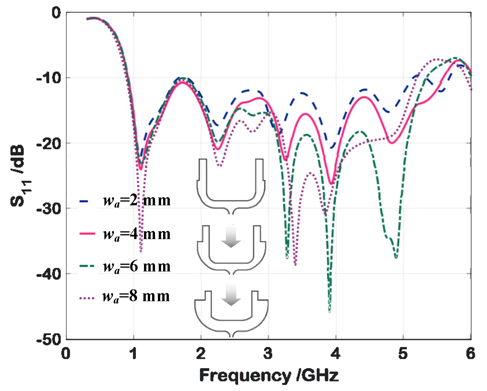
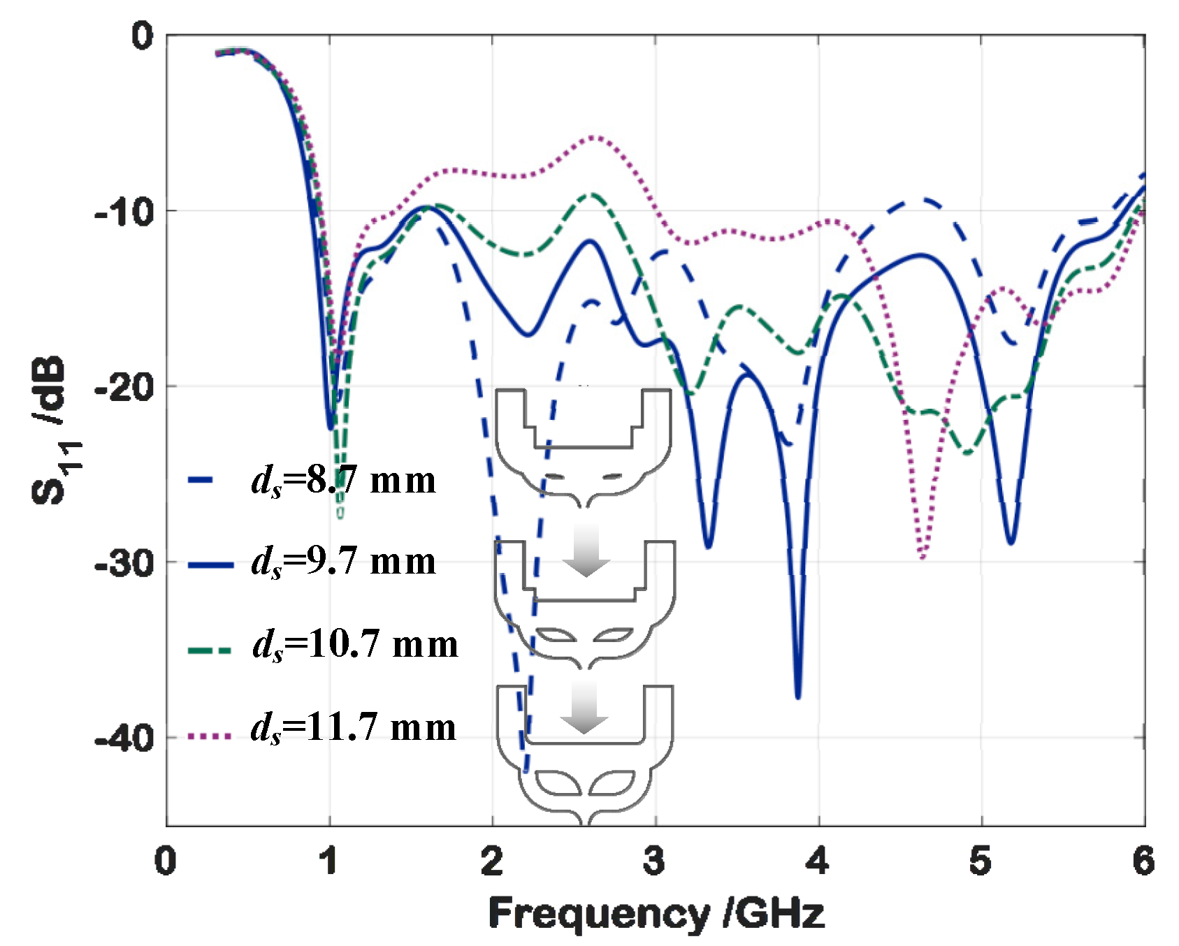
2.2. Parameter Analysis

In order to comprehensively investigate the effect of critical parameters on the impedance BW, a parameter analysis was conducted. Both of the proposed antennas were designed on the same substrate (FR4) as the normal antenna. The width, length and position of the added stubs that determine the impedance BW to a great extent were studied by changing one parameter at a time and fixing others. The simulation results were obtained by using the Ansoft simulation software high-frequency structure simulator (HFSS).
Figure 4 shows the reflection coefficient of antenna A with the varying width of the added stub (wa). When wa varied from 2 mm to 8 mm, the reflection coefficient curve showed little change near the frequency of 1 GHz. As wa reduced, the upper limiting frequency shifted to a higher frequency. This showed that better impedance matching could be obtained at high frequency with a smaller wa. However, the reflection coefficient will be worse if a too small wa is selected. Therefore, the proper selection of the width dimension is very important.
Figure 5 shows the effect of different distances (ds) on the reflection coefficient of antenna B. When the distance (ds) varied from 8.7 mm to 11.7 mm, an inconspicuous difference could be found at the frequency of 1 GHz. As the ds increased, the reflection coefficient in the middle of the frequency band became worse, while a too small ds worsened the reflection coefficient at high frequency. The conclusion was drawn that the effect of ds at the low frequency can be ignored, but that it contributed a great deal to the impedance matching over the whole bandwidth. To improve the BW characteristics, the distance between the added stub and the main stub should be set properly.

3. Results and Discussion

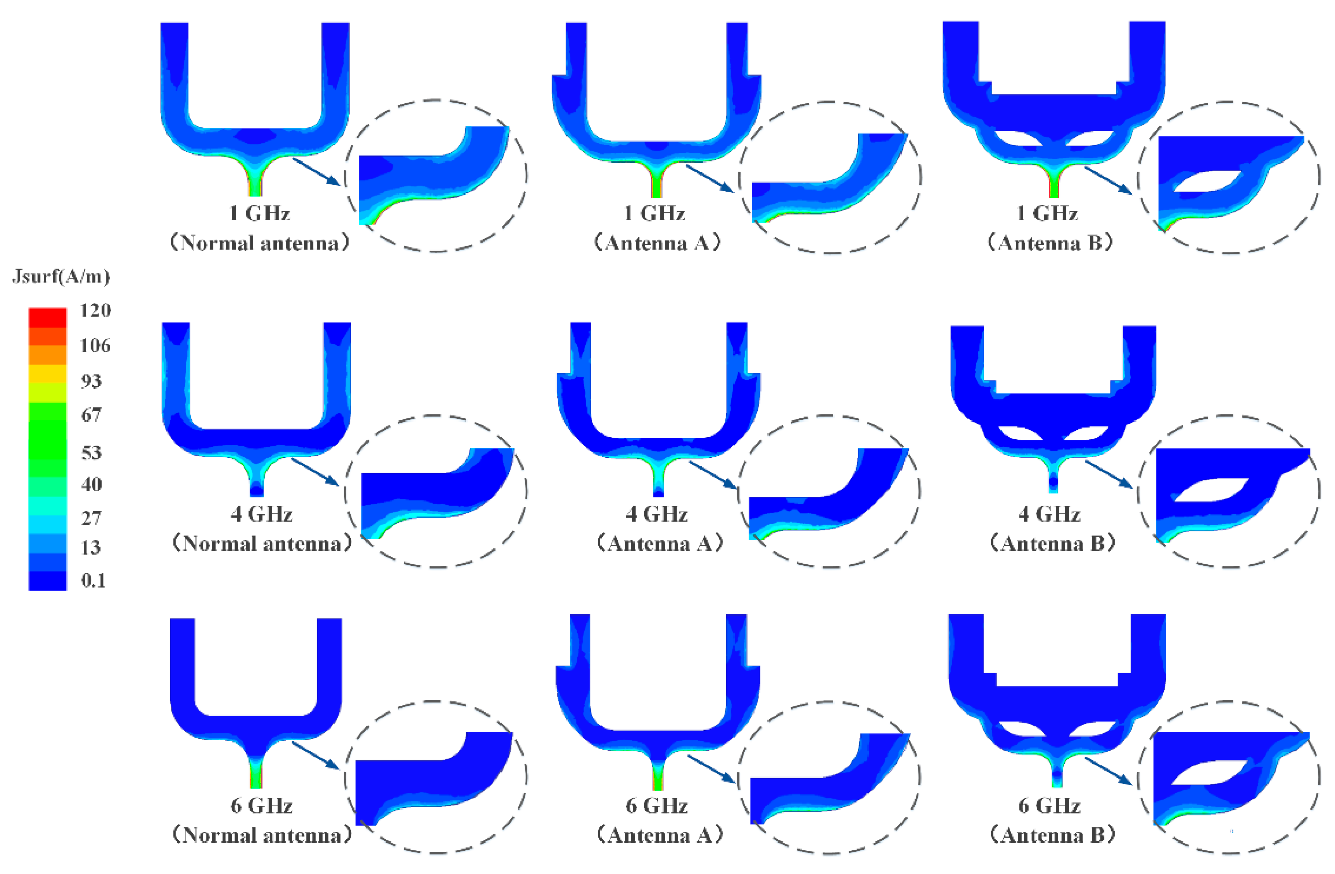
3.1. Simulation Results

The two proposed antennas were designed with the help of simulation software. The final structural parameters were optimized, as shown in Table 1. All these parameters were being optimized by the Ansoft HFSS sweeper and optimizer tool to obtain the best parameter set, except the width of the microstrip feed line, which was kept fixed to satisfy the standard input impedance of 50 Ω.
To make a comparison with the proposed antennas, the structural parameters of the normal antenna were also optimized. The simulated reflection coefficients are given in Figure 6, which shows the comparison between the proposed antennas and the normal antenna. By smoothing the stub and slot on the ground plane as much as possible, an impedance BW of 130.7% (0.9–4.3 GHz) was obtained, while the impedance BW for the WS antenna with rectangular corners was 100% (0.9–2.7 GHz). Here, the lowest resonant frequency was in agreement with the previous theoretical calculation.
It can be seen, by introducing an extra stub, the impedance BWs (S11 < −10 dB) for both antenna A and antenna B became wider, reaching 144% (0.9–5.55 GHz) and 147% (0.9–5.90 GHz), respectively. Adding an extra fork-shaped stub was confirmed to be an effective way to improve the BW characteristics.
To better understand the antennas’ behavior, the simulated current patterns of the proposed antennas were compared with the normal antenna, as shown in Figure 7, which depicts the current distributions along the tuning stub at 1 GHz, 4 GHz and 6 GHz, respectively. At the frequency of 1 GHz, there was a strong current on the outer boundary of the stub for all three antennas. Similar current distributions were observed at the frequency of 4 GHz. At the frequency of 6 GHz, the current on the stub of the normal antenna became weak, while for the proposed antennas a strong current could still be obtained on the stub. It can be seen that the resonant mode of the current at high frequency changed as a result of introducing the extra stub. By means of a reasonable structural design and the appropriate loading of the extra stub, the broadband matching was able to be realized.

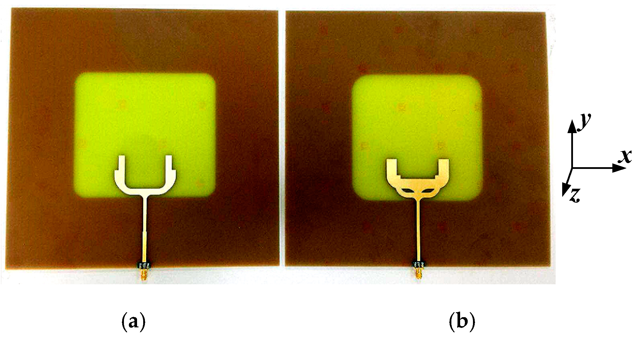
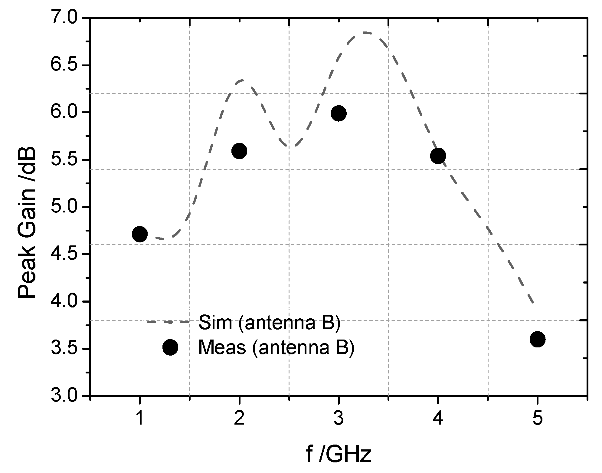
3.2. Fabrication and Measurement

To validate the proposed technology, the proposed antennas (antenna A and antenna B) were fabricated. Figure 8 shows the fabricated prototype of the proposed WS antennas. The reflection coefficients of the fabricated antennas were measured by a vector network analyzer and the results were compared with those obtained from the simulation, as shown in Figure 9 and Figure 10.
The impedance BW of antenna A, which ranged from 0.9 GHz to 5.6 GHz, reached 144% for S11 < −8 dB. The measured reflection coefficient of antenna B seemed to be much better. The impedance BW of antenna B ranged from 0.9 GHz to 6.1 GHz, indicating a relative BW of 148.6% or 5.78 octaves for S11 < −10 dB. The measured results were in accordance with those from the simulation. It is noted that, for antenna A, the measured and simulated results showed the same resonant frequency points under 5 GHz. However, the measured reflection coefficient of antenna A was higher than −10 dB at some frequency points. For antenna B, the measured reflection coefficient was lower than −10 dB in the whole bandwidth, but the position of the resonant frequency points was slightly offset. The existence of some discrepancy between the measured and simulated results for both of the proposed antennas was mainly due to the effect of SMA connector soldering and fabrication error.
Figure 11 shows the radiation patterns that were measured at 1 GHz, 2 GHz, 4 GHz and 5 GHz. The radiation patterns of the two proposed antennas were very similar. Both of the antennas exhibited a stable dipolar pattern on the yoz-plane (E-plane) and a stable nearly-omnidirectional pattern on the xoz-plane (H-plane). It can be seen that good agreement was achieved between the simulation and the measured results.
Figure 12 shows the simulated and measured peak gain of the proposed antenna B. The measured peak gain of antenna B was 4.71 dB at the frequency of 1 GHz. It can be seen that the measured results were in good agreement with the simulation results.

4. Conclusions

In this paper, a multiple-resonance technique to achieve a wide BW for printed WS antennas with a fork-shaped stub was presented. Two designs improved from the normal WS antenna with a fork-shaped stub were investigated to validate the technique. By introducing an extra stub into the main fork-shaped stub, the BW characteristics were able to be significantly improved. By choosing the loading position properly and optimizing the dimensions, an impedance BW of 148.6% was achieved. In addition, the proposed antennas exhibited stable far-field radiation characteristics within the operating bandwidth. Moreover, the antennas were easy to fabricate and can be applied in various wireless communication systems.

Author Contributions

Validation and writing—original draft, K.L.; conceptualization and methodology, T.D.; writing—review and editing, Z.X.

Funding

This research was funded by the Innovation Funds for Aerospace Science and Technology, grant number JSKFJ201604120007 and the Innovation Funds of the China Academy of Space Technology, grant number CAST2016021.

Acknowledgments

The authors would like to thank Zhihui Liu and Jingwen He for their support in reviewing.

Conflicts of Interest

The authors declare no conflict of interest.

References

  1. Li, W.T.; Hei, Y.Q.; Grubb, P.M.; Shi, X.W.; Chen, R.T. Compact inkjet-printed flexible MIMO antenna for UWB applications. IEEE Access. 2018, 6, 50290–50298. [Google Scholar] [CrossRef]
  2. Sipal, D.; Abegaokar, M.P.; Koul, S.K. Easily extendable compact planar UWB MIMO antenna array. IEEE Antennas Wirel. Propag. Lett. 2017, 16, 2328–2331. [Google Scholar] [CrossRef]
  3. Tang, M.C.; Shi, T.; Ziolkowski, R.W. Planar ultrawideband antennas with improved realized gain performance. IEEE Trans. Antennas Propag. 2016, 64, 61–69. [Google Scholar] [CrossRef]
  4. Eskandari, H.; Booket, M.R.; Kamyab, M.; Veysi, M. Investigations on a class of wideband printed slot antenna. IEEE Antennas Wirel. Propag. Lett. 2010, 9, 1221–1224. [Google Scholar] [CrossRef]
  5. Gangwar, S.P.; Gangwar, K.; Kumar, A. A compact modified hexagonal slot antenna for wideband applications. Electromagnetics 2018, 38, 339–351. [Google Scholar] [CrossRef]
  6. Bod, M.; Hassani, H.R.; Taheri, M.M.S. Compact UWB printed slot antenna with extra bluetooth, GSM, and GPS bands. IEEE Antennas Wirel. Propag. Lett. 2012, 11, 531–534. [Google Scholar] [CrossRef]
  7. Qing, X.; Chen, Z.N. Compact coplanar waveguide-fed ultra-wideband monopole-like slot antenna. IET Microw. Antennas Propag. 2009, 3, 889–898. [Google Scholar] [CrossRef]
  8. Moghadasi, M.N.; Sadeghzadeh, R.A.; Asadpor, L.; Soltani, S.; Virdee, B.S. Improved band-notch technique for ultra-wideband antenna. IET Microw. Antennas Propag. 2010, 4, 1886–1891. [Google Scholar] [CrossRef]
  9. Heshmat, N.F.; Nourinia, J.; Ghobadi, C. Band-notched ultra-wideband printed open-slot antenna using variable on-ground slits. Electron. Lett. 2009, 45, 1060–1061. [Google Scholar] [CrossRef]
  10. Denidni, T.A.; Habib, M.A. Broadband printed CPW-fed circular slot antenna. Electron. Lett. 2006, 42, 135–136. [Google Scholar] [CrossRef]
  11. Ghaderi, M.R.; Mohajeri, F. A compact hexagonal wide-slot antenna with microstrip-fed monopole for UWB application. IEEE Antennas Wirel. Propag. Lett. 2011, 10, 682–685. [Google Scholar] [CrossRef]
  12. Jan, J.Y.; Wang, L.C. Printed wideband rhombus slot antenna with a pair of parasitic strips for multiband applications. IEEE Trans. Antennas Propag. 2009, 57, 1267–1270. [Google Scholar] [CrossRef]
  13. Ojaroudi, M.; Ojaroudi, N. Ultra-wideband small rectangular slot antenna with variable band-stop function. IEEE Trans. Antennas Propag. 2014, 62, 490–494. [Google Scholar] [CrossRef]
  14. Fan, S.T.; Yin, Y.Z.; Lee, B.; Hu, W.; Yang, X. Bandwidth enhancement of a printed slot antenna with a pair of parasitic patches. IEEE Antennas Wirel. Propag. Lett. 2012, 11, 1230–1233. [Google Scholar] [CrossRef]
  15. Chiang, M.J.; Hung, T.F.; Sze, J.Y.; Bor, S.S. Miniaturized dual-band CPW-fed annular slot antenna design with arc-shaped tuning stub. IEEE Trans. Antennas Propag. 2010, 58, 3710–3715. [Google Scholar] [CrossRef]
  16. Tasouji, N.; Nourinia, J.; Ghobadi, C.; Tofigh, F. A novel printed UWB slot antenna with reconfigurable band-notch characteristics. IEEE Antennas Wirel. Propag. Lett. 2013, 12, 922–925. [Google Scholar] [CrossRef]
  17. Valizade, A.; Ghobadi, C.; Nourinia, J.; Ojaroudi, M. A novel design of reconfigurable slot antenna with switchable band notch and multiresonance functions for UWB applications. IEEE Antennas Wirel. Propag. Lett. 2012, 11, 1166–1169. [Google Scholar] [CrossRef]
  18. Xu, R.; Li, J.Y.; Liu, J. A design of broadband circularly polarized C-Shaped slot antenna with sword-shaped radiator and its array for L/S-band applications. IEEE Access. 2018, 6, 5891–5896. [Google Scholar] [CrossRef]
  19. Dastranj, A. Optimization of a printed UWB antenna: Application of the invasive weed optimization algorithm in antenna design. IEEE Antenna Propagation Mag. 2017, 59, 48–57. [Google Scholar] [CrossRef]
  20. Sze, J.Y.; Wong, K.L. Bandwidth enhancement of a microstrip-line-fed printed wide-slot antenna. IEEE Trans. Antennas Propag. 2001, 49, 1020–1024. [Google Scholar] [CrossRef]
  21. Chair, R.; Kishk, A.A.; Lee, K.F. Ultrawide-band coplanar waveguide-fed rectangular slot antenna. IEEE Antennas Wirel. Propag. Lett. 2004, 3, 227–229. [Google Scholar] [CrossRef]
  22. Li, P.C.; Liang, J.X.; Chen, X.D. Study of printed elliptical/circular slot antennas for ultrawideband applications. IEEE Trans. Antennas Propag. 2006, 54, 1670–1675. [Google Scholar] [CrossRef]
  23. Arya, A.K.; Aziz, R.S.; Park, S. Planar ultra-wideband printed wide-slot antenna using fork-like tuning stub. Electron. Lett. 2015, 51, 550–551. [Google Scholar] [CrossRef]
  24. Emadian, S.R.; Shokouh, J.A. Very small dual band-notched rectangular slot antenna with enhanced impedance bandwidth. IEEE Trans. Antennas Propag. 2015, 63, 4529–4534. [Google Scholar] [CrossRef]
Figure 1. Top views of the two types of proposed antenna.
Electronics 08 00347 g001
Figure 2. Geometry and configuration of the normal printed WS antenna with a round corner on the stub and ground plane.
Electronics 08 00347 g002
Figure 3. Geometries and configurations of the proposed antennas (adding extra stubs onto the main fork-shaped stub).
Electronics 08 00347 g003
Figure 4. Simulated reflection coefficient of the proposed antenna A with different widths (wa) of the added stub.
Electronics 08 00347 g004
Figure 5. Simulated reflection coefficient of the proposed antenna B with different distances (ds) between the two stubs.
Electronics 08 00347 g005
Figure 6. Simulated reflection coefficients of the proposed antennas, compared with the normal WS antenna.
Electronics 08 00347 g006
Figure 7. Simulated current distributions of the normal WS antenna and the proposed antennas at a frequency of 1 GHz, 4 GHz, and 6 GHz.
Electronics 08 00347 g007
Figure 8. Photographs of the fabricated antennas with a soldered SMA connector; (a) antenna A; (b) antenna B.
Electronics 08 00347 g008
Figure 9. Reflection coefficients of the proposed antenna A, comparing the measured result with the simulation.
Electronics 08 00347 g009
Figure 10. Reflection coefficients of the proposed antenna B, comparing the measured result with the simulation.
Electronics 08 00347 g010
Figure 11. Radiation patterns of the proposed antennas; (a) 1 GHz; (b) 2 GHz; (c) 4 GHz; (d) 5 GHz.
Electronics 08 00347 g011
Figure 12. Simulated and measured peak gain of the proposed antenna B.
Electronics 08 00347 g012
Table 1. Optimal structural parameters of the proposed antennas.
DescriptionAntenna A (mm)Antenna B (mm)
Length of the horizontal sectionla = 17.0lb = 16.48
Width of the added stubwa = 4.0wb = 4.22
Inside radius of the bendra = 12.30rb = 6.08
Length of the vertical sectionda = 4.35db = 8.82
Distance between the two stubs/ds = 9.70
Width of the main stubw0 = 4.93w0 = 8.33
Horizontal length of the main stubl0 = 21.2l0 = 30.52
Vertical length of the main stubd0 = 22.08d0 = 14.77

