Article

Semiactive Hybrid Energy Management System: A Solution for Electric Wheelchairs

School of Electrical Engineering, Pusan National University, Busandaehak-ro 63beon-gil, Geumjeong-gu, Busan 46241, Korea
*
Author to whom correspondence should be addressed.
Electronics 2019, 8(3), 345; https://doi.org/10.3390/electronics8030345
Submission received: 21 February 2019 / Revised: 15 March 2019 / Accepted: 20 March 2019 / Published: 21 March 2019

Abstract

:
Many disabled people use electric wheelchairs (EWs) in their daily lives. EWs take a considerable amount of time to charge and are less efficient in high-power-demand situations. This paper addresses these two problems using a semiactive hybrid energy storage system (SA-HESS) with a smart energy management system (SEMS). The SA-HESS contained a lithium-ion battery (LIB) and supercapacitor (SC) connected to a DC bus via a bidirectional DC–DC converter. The first task of the proposed SEMS was to charge the SA-HESS rapidly using a fuzzy-logic-controlled charging system. The second task was to reduce the stress of the LIB. The proposed SEMS divided the discharging operation into starting-, normal-, medium-, and high-power currents. The LIB was used in normal conditions, while the SC was mostly utilized during medium-power conditions, such as starting and uphill climbing of the EW. The conjunction of LIB and SC was employed to meet the high-power demand for smooth and reliable operation. A prototype was designed to validate the proposed methodology, and a comparison of the passive hybrid energy management system (P-HESS) and SA-HESS was performed under different driving tracks and loading conditions. The experimental results showed that the proposed system required less charging time and effectively utilized the power of the SC compared with P-HESS.

1. Introduction

Currently, there are an estimated 600 million people aged 60 years or older in the world [1]. In addition, people disabled due to traffic and lower-limb accidents add another 9 million to the count, with an increasing rate of 500,000 per year. The quality of life of elderly or disabled people is restricted. However, advancements in different assistive devices, such as wheelchairs, has led to an increase in their range of activities [2]. While using electric wheelchairs (EWs), people want to travel greater distances and reduce the amount of time it takes to charge the battery [3].
Various technologies have been employed for EWs, but their efficiency greatly depends on the characteristics of their energy storage system (ESS) [4,5]. Various ESSs, including lithium-ion batteries (LIBs), lead–acid batteries, and nickel metal hydride batteries, are used in vehicular applications [6,7]. Among these, LIBs are a widely used energy source due to their attractive properties such as high energy density, low self-discharge rate, and long lifecycle [8,9,10]. A comparison of different properties of batteries is shown in Figure 1. On the other hand, in vehicular applications, the battery faces many challenges, such as the need for high power demand during acceleration or uphill climbing modes. Although a high-power battery is possible to tackle this problem, these batteries are quite bulky and expensive [11,12]. The power specifications of the LIB are very low, and the peak-to-average-power ratio ranges between 0.5 to 2 [13], which makes LIBs unpromising in high-power-demand situations. Therefore, supercapacitors (SCs) can be used as a secondary ESS.
The power and energy density of SCs range from 1000 to 5000 W/kg and 1 to 10 Wh/kg, respectively [16]. SCs have charging and discharging capabilities of 10–20 times more than LIBs [17]. SCs are not a replacement for LIBs but provide the power needed for EW systems when accelerating up a slope. In addition, they have a longer lifecycle and a wider range of operating temperatures (−4 to +70 °C) than LIBs, although they do have low energy density [18]. In electric vehicles (EVs), the stress on the battery is higher than that in a hybrid electric vehicle (HEV) due to deep discharging (~80% for EVs and ~10% for HEVs) [19]. A hybrid energy storage system (HESS) is a combination of SC and LIB, which combines the advantages of both devices to fulfill the requirements of high energy and power densities. SCs are normally used for high power storage, and LIBs are used as a high-energy-storage unit. The SC is utilized for the high power demand of the powertrain, while the LIB is used in low-power situations [20].
An energy management system (EMS) is required to fully utilize the energy of both storage units effectively [21]. The EMS presented in [22,23] is based on the frequency decoupling method to protect the battery from abrupt changes in the load. HESSs can be easily divided into three main topologies: passive HESS (P-HESS), semiactive HESS (SA-HESS), and fully active HESS [24]. A P-HESS is the direct coupling of two or more energy storage devices without a power converter [25]. This has several benefits over a standalone LIB as a power source (e.g., higher peak power capability, higher efficiency, and long battery lifecycle) [26]. Although it is simple to implement, there are some limitations. Power sharing is uncontrollable because the two storage systems are not decoupled [27,28]. Napoli et al. [17] used an ultracapacitor connected in parallel to a battery with no power converter between the two sources. In a P-HESS, power sharing between the LIB and SC is determined by their respective resistance, and the resulting terminal voltage follows the discharge curve of a battery [16]. The energy storage device should be decoupled for efficient operations with respect to its characteristics [29]. In contrast, the degree of controllability is increased using a fully active HESS, but there are some disadvantages, such as increased system losses, weight, and cost. In addition, efficiency also decreases because of the additional converter [20]. Similarly, a modular multilevel fully active HESS also adds complexity and cost. This will also affect the sensitivity of the system, with a failure of one DC–DC converter causing system failure [30]. The SA-HESS is a tradeoff between cost and performance. This system employs only one DC–DC converter and most control strategies can be implemented on this topology [31].
The cell voltage of an LIB is very low. Therefore, a string of batteries is generally used. An imbalanced cell voltage because of the series connection of LIBs causes an increase in temperature, deep discharging, overcharging, and reduced lifecycle and capacity of the battery [32]. Different engineering techniques have been used to control and monitor battery parameters (e.g., state of charge (SOC), voltage, current, and temperature) [33]. For voltage balancing, a special type of charging circuit is required [34,35]. Various fast-charging techniques are used to charge LIBs, such as constant current and constant voltage (CC/CV), a multistage current charging algorithm, model-based charging, a pulse charging algorithm, and a fuzzy logic controller (FLC) [36,37,38]. The CC/CV technique is simple and computationally efficient [39]. This method has two modes. First, it reaches the defined voltage level while providing a CC to the battery. In the second step, a CV is supplied, and the battery current begins to decrease exponentially [40]. This procedure requires a high current if the battery needs to be charged in a short time, but this increases the battery temperature dramatically, which reduces the lifecycle. In contrast, it takes more time to charge a battery if the current is lower. Huang et al. introduced different intervals to determine the optimal current using FLC [41].
This paper proposes a semiactive hybrid energy management system comprised of SA-HESS and a smart energy management system (SEMS). The proposed methodology charges the HESS smartly using an FLC. The temperature is used as a feedback, which is thermally and electrically favorable to achieve a long lifetime for the ESS. The proposed SEMS discharges the SA-HESS smartly according to the desired load current. Several experiments have been performed to compare the proposed technique with P-HESS.
The rest of the paper is organized into five sections. Section 2 describes an overview and the methodology of the proposed system. Section 3 presents the experimental installation. Section 4 reports the results from the experimental study. Section 5 is the discussion of the results, and Section 6 concludes the paper.

2. Methodology

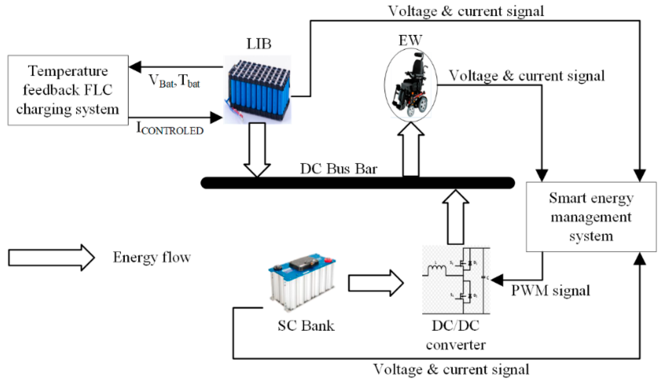
2.1. Overview of the Proposed Methodology

This section provides an overview of the proposed SA-HESS for EWs. At high power/current demand, the use of only an LIB is ineffective and the LIB discharges very rapidly because of the lower power density. Therefore, in the proposed technique, an SC was used as a parallel controlled power source in the SA-HESS. The required power was determined according to the SOC/voltage of the SC and LIB. Figure 2 presents the proposed system for EWs. In the SA-HESS, the LIB was used as a high energy unit, which was connected in parallel to the load via a bus link. The SC was used as a high-power unit, which was connected to the DC bus via a bidirectional converter. The CC/CV charging system was replaced with a temperature (Tbat) feedback FLC charging system. The controlled current (Icontrolled) was supplied as the optimal charging current to the LIB. The SC and LIB provided the desired current to the load, which was controlled using an Arduino microcontroller. A bidirectional converter was used in boost mode, whereas discharging and buck mode were used in charging mode [42]. The output voltage of SC (VSC) varied according to its state of charge, while the battery voltage (Vbat) remained almost constant. The boost converter was used to maintain the VSC relative to the reference (bus/battery) voltage. The converter generated the pulse width modulation (PWM) signal according to the reference value [43]. The load current (IL) was sensed using a current sensor and applied as a feedback signal for the SC (ISC) and LIB (Ibat) current. The ISC and Ibat smartly contributed according to the requirement of IL.

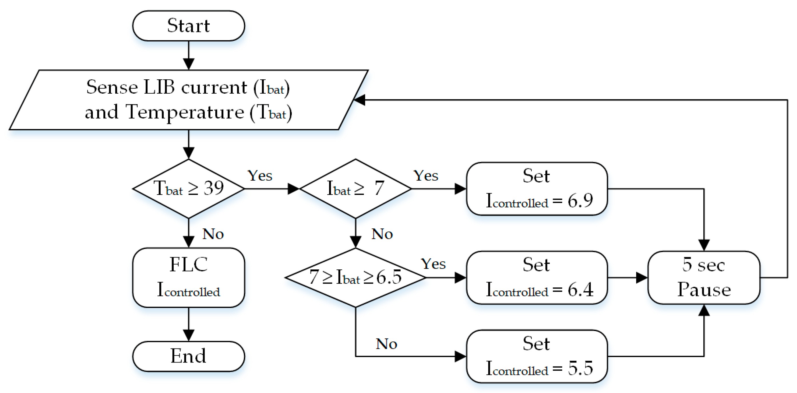
2.2. Fast-Charging System for EW

FLC is well suited to anticipating a battery’s nonlinear behavior because it is robust, easily adaptive, and does not require any mathematical model. The FLC is classified into four parts [44]: Fuzzifier—in the fuzzifier, linguistic fuzzy sets are obtained from the truth value of the membership function. Fuzzy rule base—the fuzzy rule base is designed from professional experience and controls the system operation. Fuzzy interface engine—the fuzzy linguistic input is transformed into a fuzzy linguistic output with respect to the controlled law stated in the fuzzy rule set. Defuzzifier—this maps the fuzzy output from the inference engine to a crisp or real value by using membership functions. The fast-charging methodology was designed using the same rule base as discussed in a previous study [45]. However, in this work, the FLC-based, fast-charging methodology was designed for a series and parallel cell combination of an LIB pack. The lowest single-cell voltage and the highest voltage difference between the two cells of the string were the inputs of the FLC to find the optimal value of the charging current. When the voltage difference between the two cells was high, then a high current was inserted to charge the LIB pack in less time.
However, at the same time, it was essential to control the temperature in order to ensure that this high current value did not affect the battery life. The threshold value and operation of the temperature control unit are shown in Figure 3. The temperature threshold value was set to 39 °C. If the temperature was below the threshold value, Icontrolled was supplied to the battery. When it crossed the threshold value, then the controller compared Ibat with the range defined in the flowchart. The value of the charging current changed according to the value shown in the flowchart.

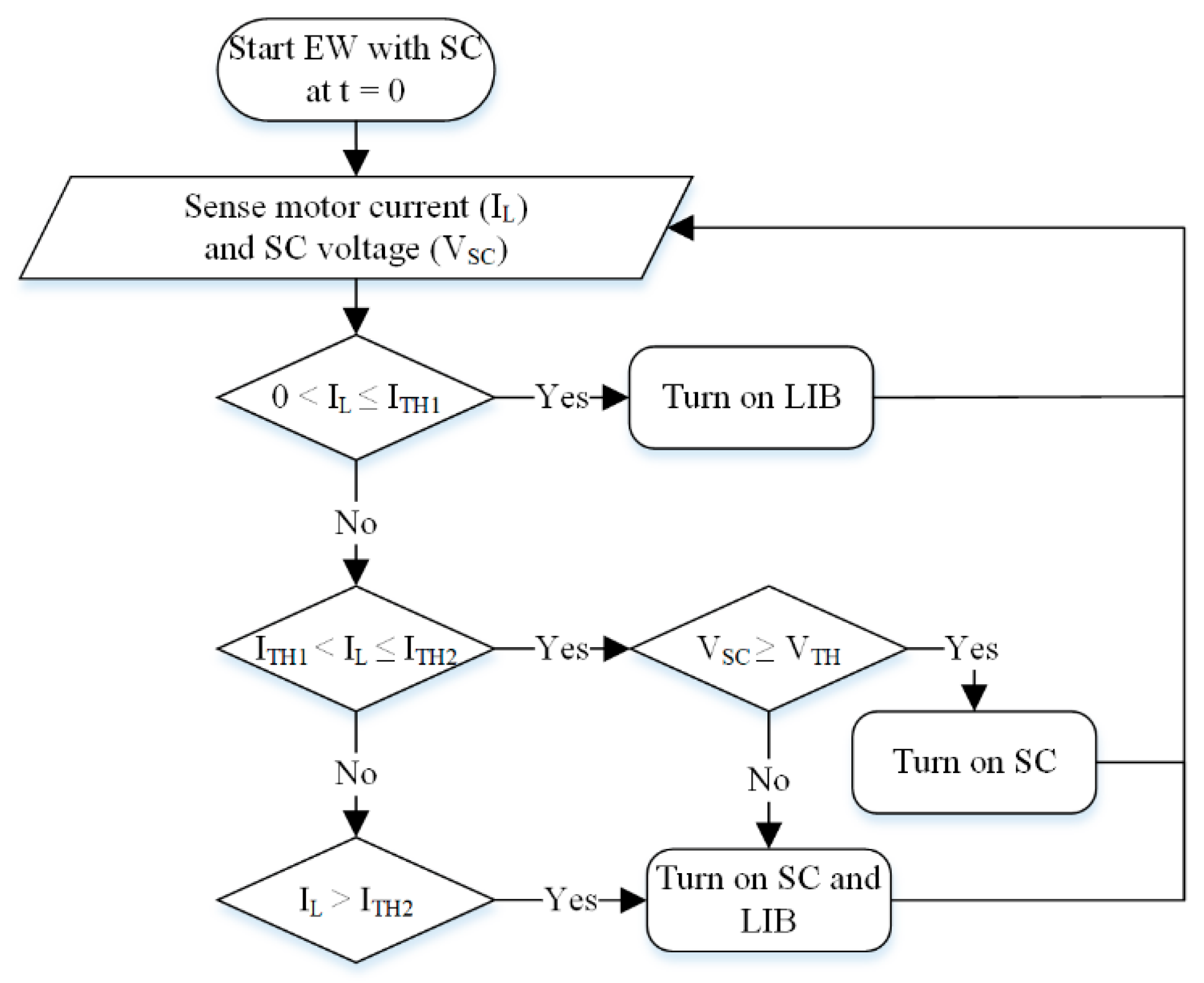
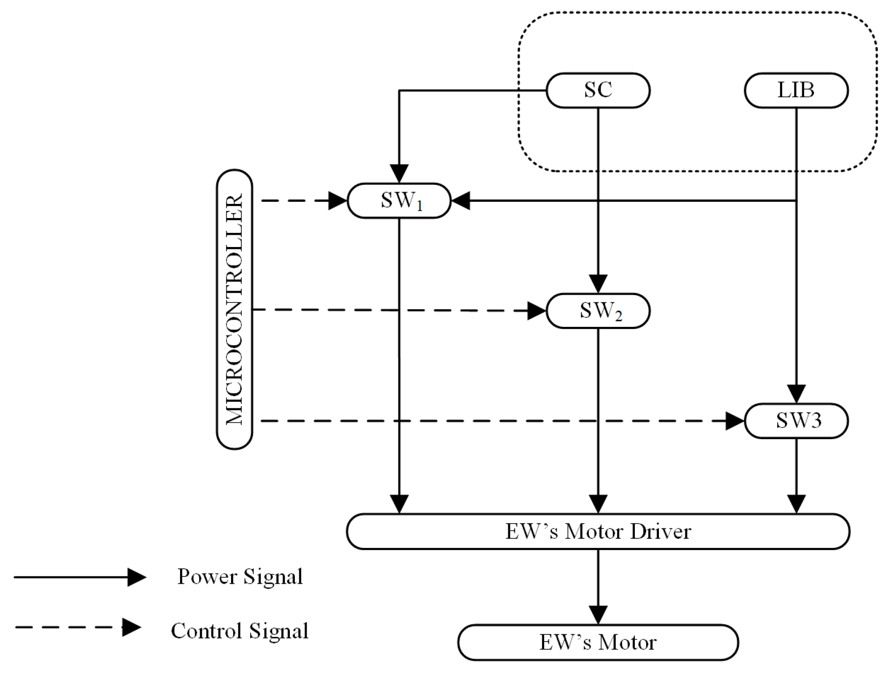
2.3. Smart Energy Management System for the SA-HESS

The power requirement for EWs motion is totally different when traveling on a flat surface than when moving on an inclined surface. A SEMS was designed to overcome the power demand. Two tracks were taken into consideration to implement the SEMS on the SA-HESS. Figure 4a,b present the normal plain track-AB and inclination track-ABCD, respectively. On track-AB, the motor of the EW did not require much power and current; however, for track-ABCD, the motor required high current/power.
The load on the EW’s motor can be calculated by using the following equations [46,47]:
F = m a f x m g   s i n   Θ
P = F × v η
I = P V b u s
where F and f x are the propulsion and friction force, respectively; m is the mass of the person and EW; and v and I are the values of the velocity and current of the EW, respectively. These equations correlated the load/power of the EW motor with the electrical current, as the bus voltage of the SA-HESS almost remains constant. So, the proposed algorithm mainly depended upon electrical current values. Figure 5 shows a flowchart of the proposed algorithm. This methodology was implemented in the Arduino MEGA 2560 interface with MATLAB (R2017a, MathWorks, Natick, MA, USA). The microcontroller, which works as a SEMS, decided the operation mode based on the sensing and analyzing HESS and load parameters (currents, SOC, and voltage). When the EW motor started, most of the power/current was supplied by the SC. VSC and IL were monitored and analyzed. If the SEMS sensed a small current that was less than the first threshold value (ITH1 = 2.5 A), it switched on the LIB circuitry to supply the required current to the load. This condition occurred when the EW was traveling along track-AB. When EW reached point B (see Figure 4b), the SEMS controller sensed a higher value of current compared with ITH1 and one lower than a second threshold current (ITH2 = 3.5 A). Soon after, SEMS would check VSC. If VSC was higher than the threshold (VTH =10 V) value, the SC supplied power to the load; otherwise, the LIB and SC supplied power together to the EW motor. Similarly, when EW was at point C (i.e., the current required to the load was more than the ITH2), the controller would switch on both the LIB and SC to fulfill the desired power demands of the load.
Figure 6 presents a simplified block of a hardware implementation for the SEMS algorithm. Solid lines represent energy flow lines, and dotted lines show the control signal flow lines. The microcontroller sent a control signal to the switch based on the condition provided by the algorithm and opened a path for the storage system to supply the desired power to the load. Three switches that connected HESS to the EW motor were used: switch SW1 connected the SC and LIB to the motor, SW2 was the interface between the SC and load, and SW3 was between the LIB and load, as shown in Figure 6.
The voltage requirement and maximum power demand determined the number of series and parallel connected branches of the devices in the storage system. The number of cells in series ( N b a t _ s ) and parallel ( N b a t _ p ) of the LIB was computed using Equations (4) and (5) [48]:
N b a t _ s = V b u s V b a t
N b a t _ p = T o t a l   A h c e l l   A h
Similarly, the number of series and parallel SCs was calculated as [48]
N S C _ s = V b u s V S C
N S C _ p = I . N S C _ s V ( t C + E S R )
where N S C _ s and N S C _ p are the number of supercapacitors connected in series and parallel, respectively, and V S C is the voltage of the supercapacitor. ESR represents the equivalent series resistance, where V and t are the voltage drop and discharging time of the supercapacitor depending upon the output current.

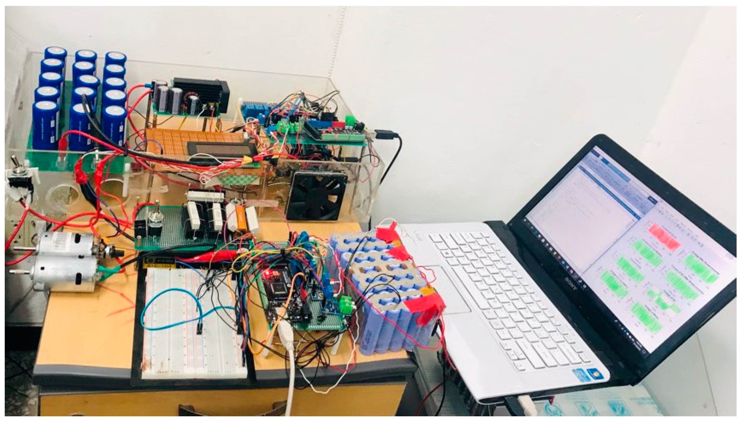
3. Experimental Setup

Figure 7 presents the experimental setup of the proposed SA-HESS prototype for an EW. A Samsung 18650 LIB (Samsung, Yongin-si, South Korea) was used in the current experiment. An SC bank with a capacitance of 350 F was used. A liquid crystal display (20 × 4 dimension) was used to indicate the mode of the HESS. The SEMS algorithm implemented in Arduino Mega 2560 was connected to the monitoring system. Different sensors were used to measure and monitor the parameters, such as the HESS temperature, current, and voltage. ACS712-20A hall effect current sensors were used for current sensing. An F30S60S power diode (ON Semiconductor, Phoenix, AZ, USA) was used. A DC motor was used as a load in this prototype.

4. Results

4.1. Performance Evaluation of Smart Energy Management System

4.1.1. Charging System Using SEMS

Figure 8 shows the voltages and temperature profiles of an LIB pack, where V1, V2, V3, V4, and Vt are the first, second, third, fourth, and overall voltages of the LIB pack, respectively. T1, T2, T3, T4, T5, T6, and T7 denote the value of different temperature sensors. The voltage and temperature were monitored to obtain the optimal value of the charging current for an LIB. At 3498 s, the temperature (T2) increased from the threshold value. To compensate for this effect, the current was reduced, as described in Section 2.2 and shown in the magnified graph.

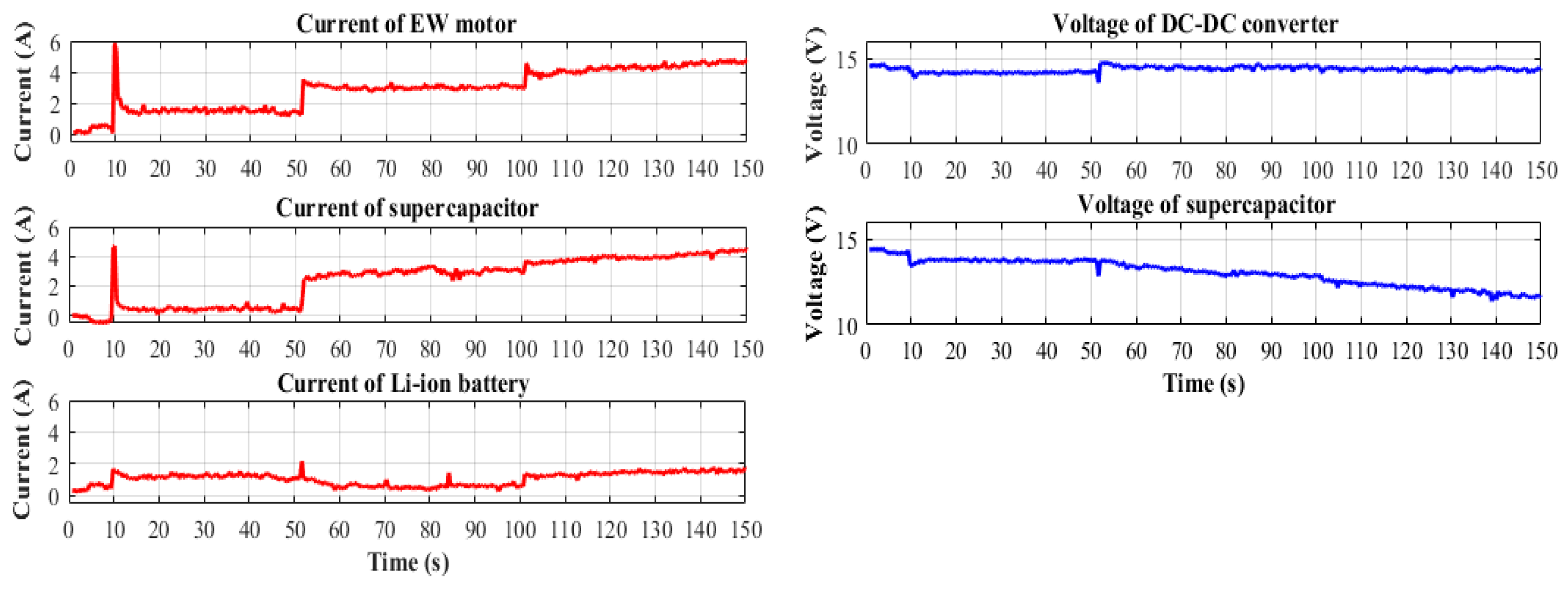
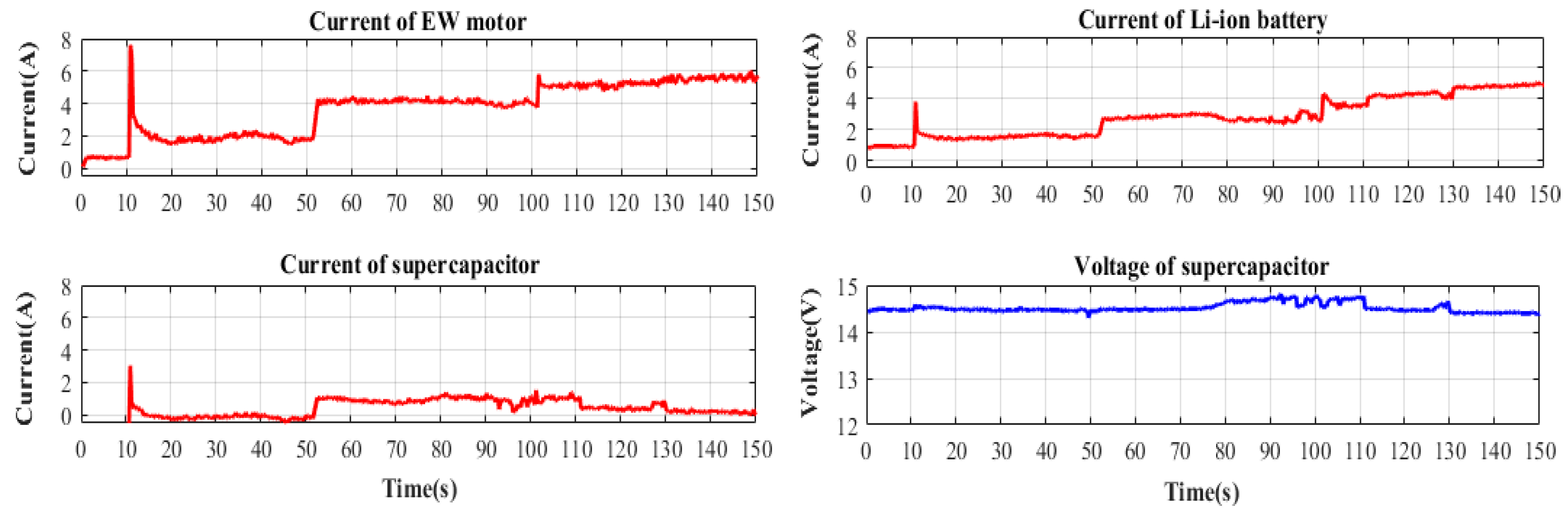
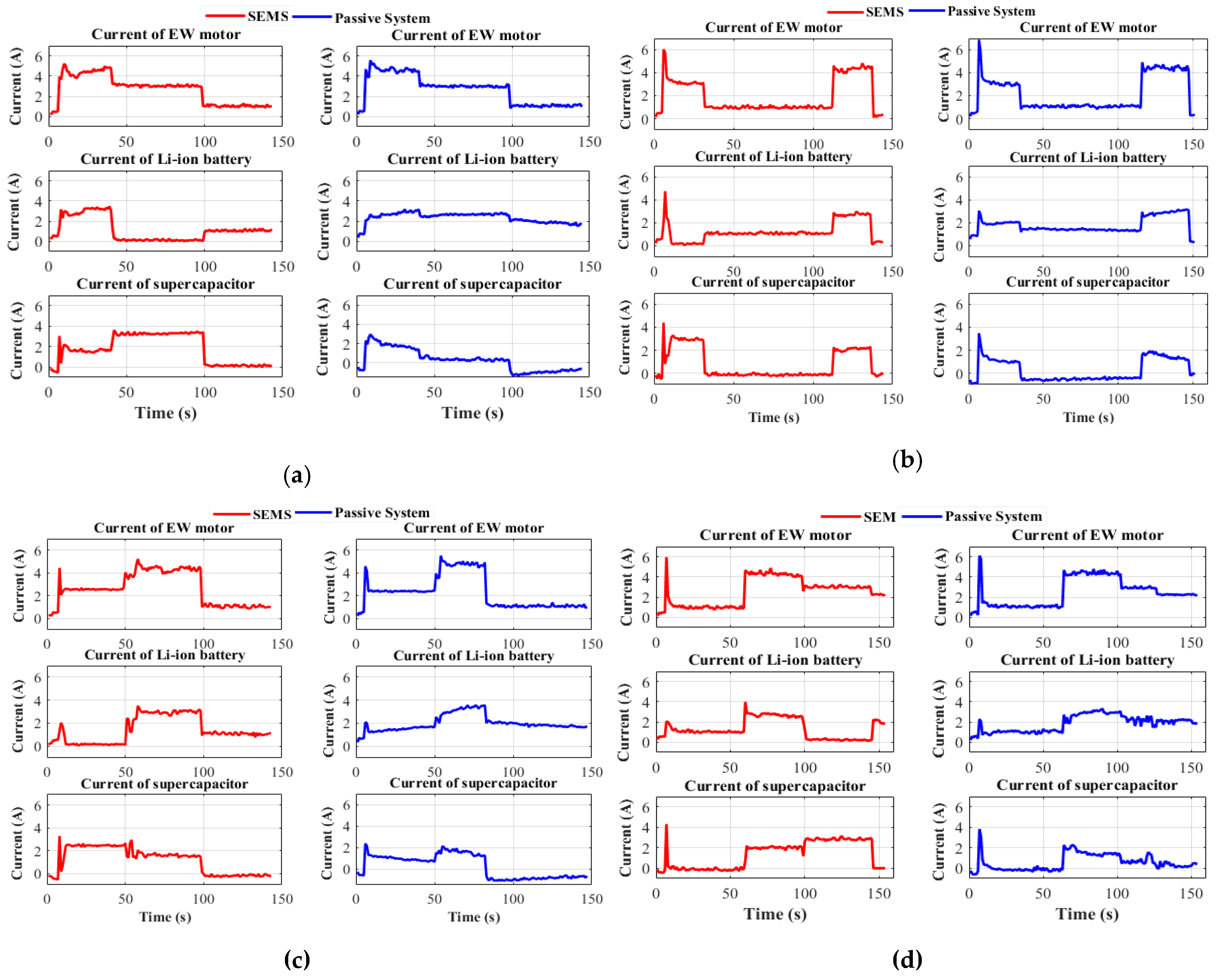
4.1.2. Discharging System Using SEMS

Two tracks were used to validate the SEMS methodology for SA-HESS, as shown in Figure 9. The EW needed a high current value to start, which was provided by the SC at the time (t) = 9 s. At t = 11 s, the EW started moving on a flat surface. On a normal surface, the EW motor required less current, which was supplied by the LIB at t = 11–50 s. At t = 51 s, the EW started to climb uphill. The EW drew more current, which was provided by the SC. Here, the stress on the LIB was reduced using the SC instead of the LIB. At t = 100 s, the EW reached the middle of the inclined surface and required more power to reach the top surface. In this case, both the LIB and SC supplied power to the load. These timeframes are discussed in detail below in the test cases considering the proposed algorithm, as described in Section 2.3.

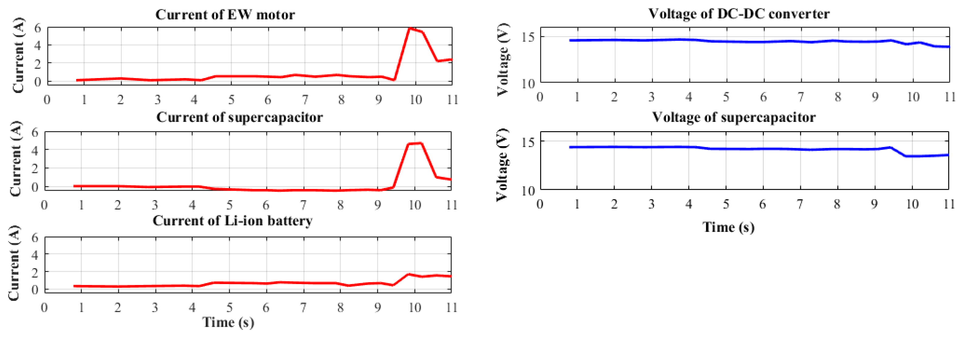
Case—EW Start (t = 0–11 s)

At the start, the EW motor required a high current for a small amount of time. The current profile in Figure 10 shows a spike at t = 10 s, indicating that the EW motor drew 6 A. The SC supplied this high pulse current. The voltage of the SC showed small variations (0.6 V), but the DC–DC converter maintained a constant voltage for smooth power transfer.

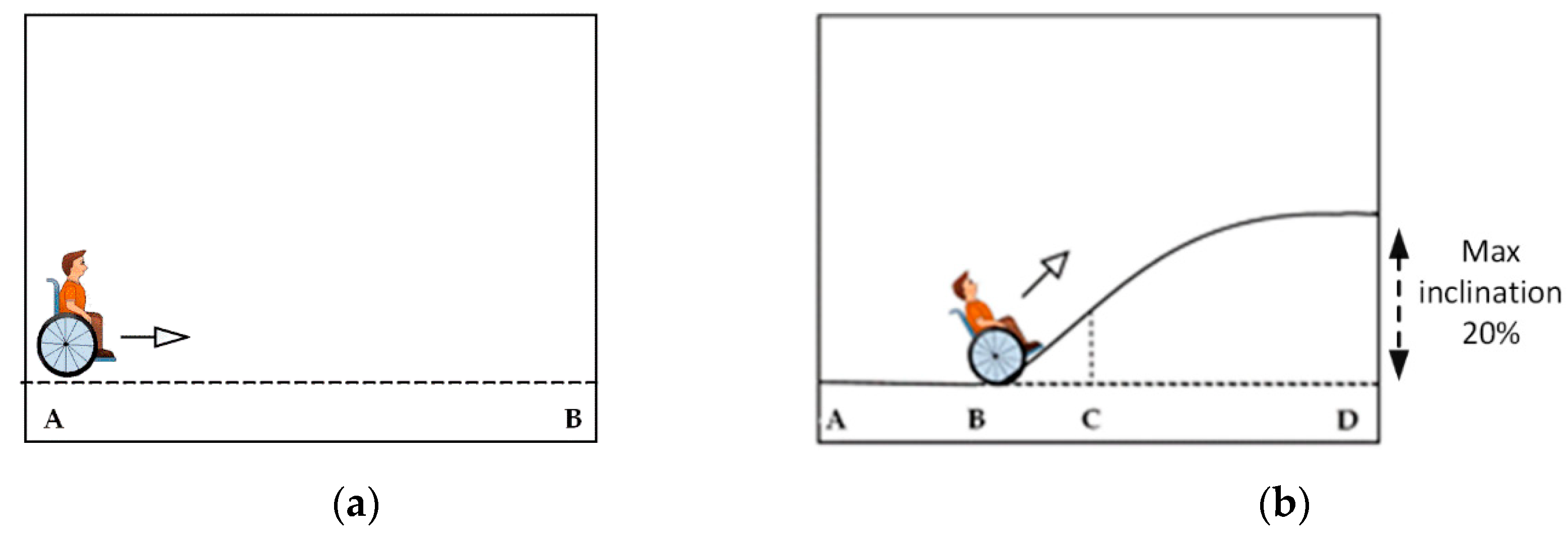
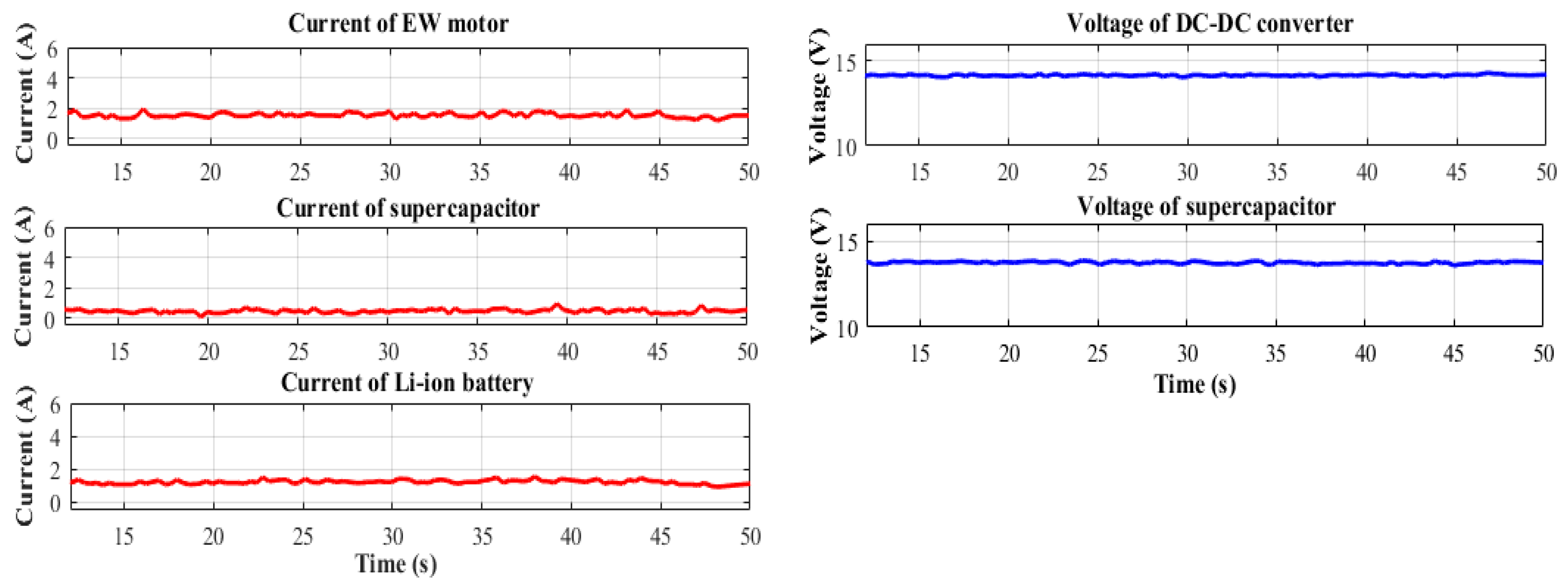
Case—Plain Track (t = 11–50 s)

From t = 11 to 50 s, the EW traveled on track-AB (from Figure 4a). The EW motor drew a 1.9-A current. SEMS enabled the LIB to supply this small amount of power to the load. The current profile in Figure 11 reveals the SC to have had an almost zero current, while the current of the LIB was 1.3 A. This confirms that only the LIB supplied a small amount of power to the load.

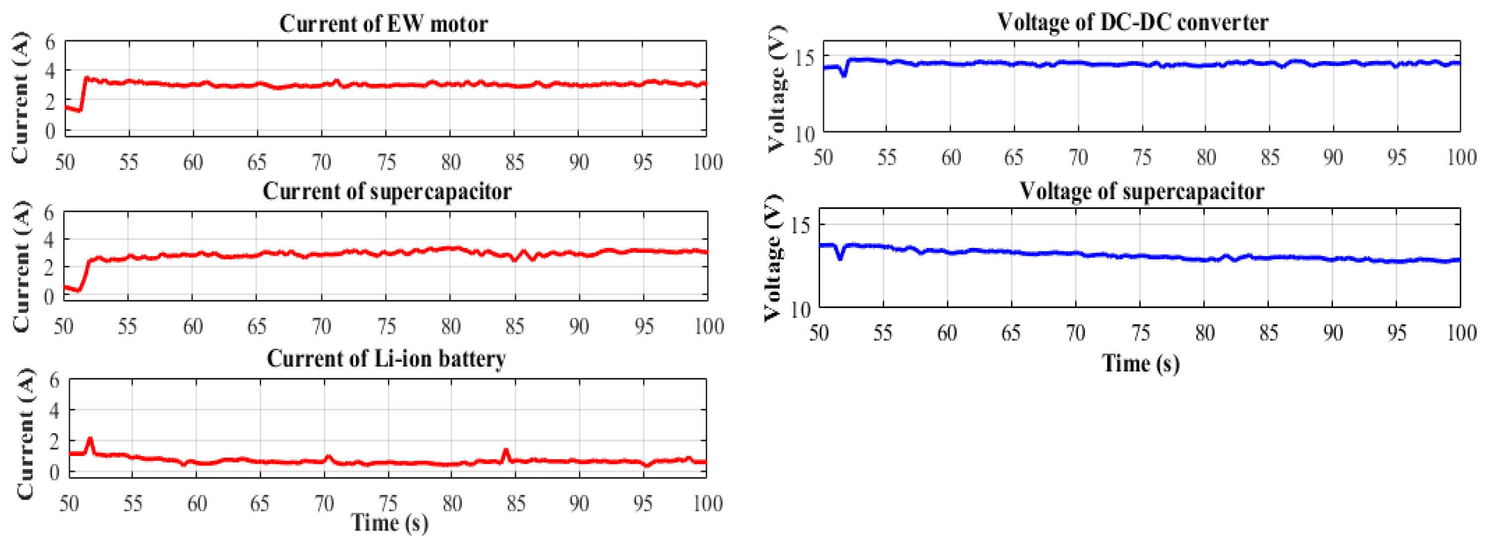
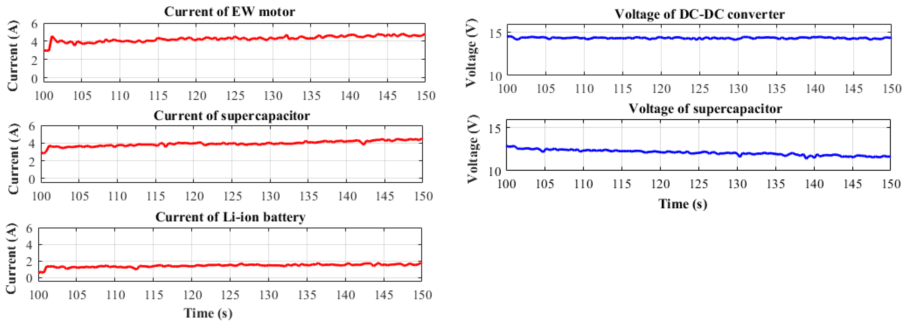
Case—Climbing Uphill (t = 51–150 s)

As shown in Figure 12, from t = 51 to 100 s, the EW traveled from points B to C (as described in Figure 4b). On this track, a 3-A current was drawn by the load. The proposed system enabled SC to supply a high power/current to the load. The SC current increased to 3 A to fulfill the power requirement of the load shown in the current of a supercapacitor in Figure 12. The voltage of the SC started decreasing, but the DC–DC converter maintained a constant voltage to fully utilize the SC. The current profile of the LIB confirmed that the LIB supplied an almost zero current, even at a high load current.
Figure 13 shows the current and voltage profile of the EW traveling from points C to D from t = 100 to 150 s. At the peak load, the proposed system supplied power from both sources. The experimental results showed that at point C, the LIB supplied approximately 1–1.7 A and the SC supplied 4 A, as shown in the current profile of the LIB and SC in Figure 13. The terminal voltage of the SC decreased from 12.9 to 11.9 V, but the DC–DC converter provided a constant voltage to the load. Regardless of acceleration, the proposed system supplied a constant LIB voltage to the load and less current, which improved the LIB lifecycle. This should also increase the traveling range of the EW.

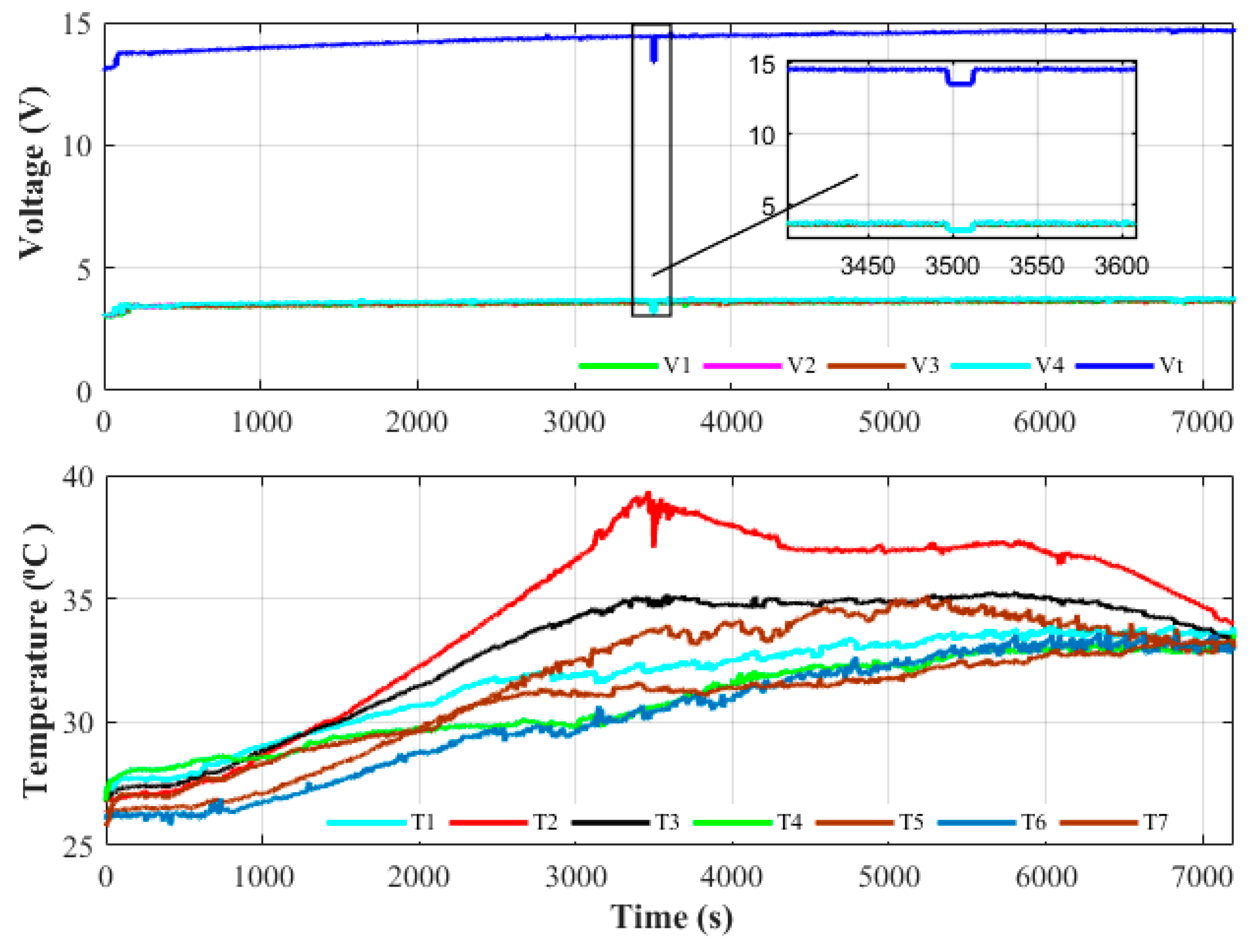
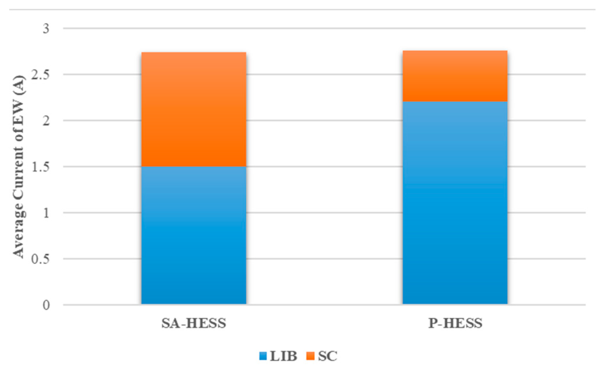
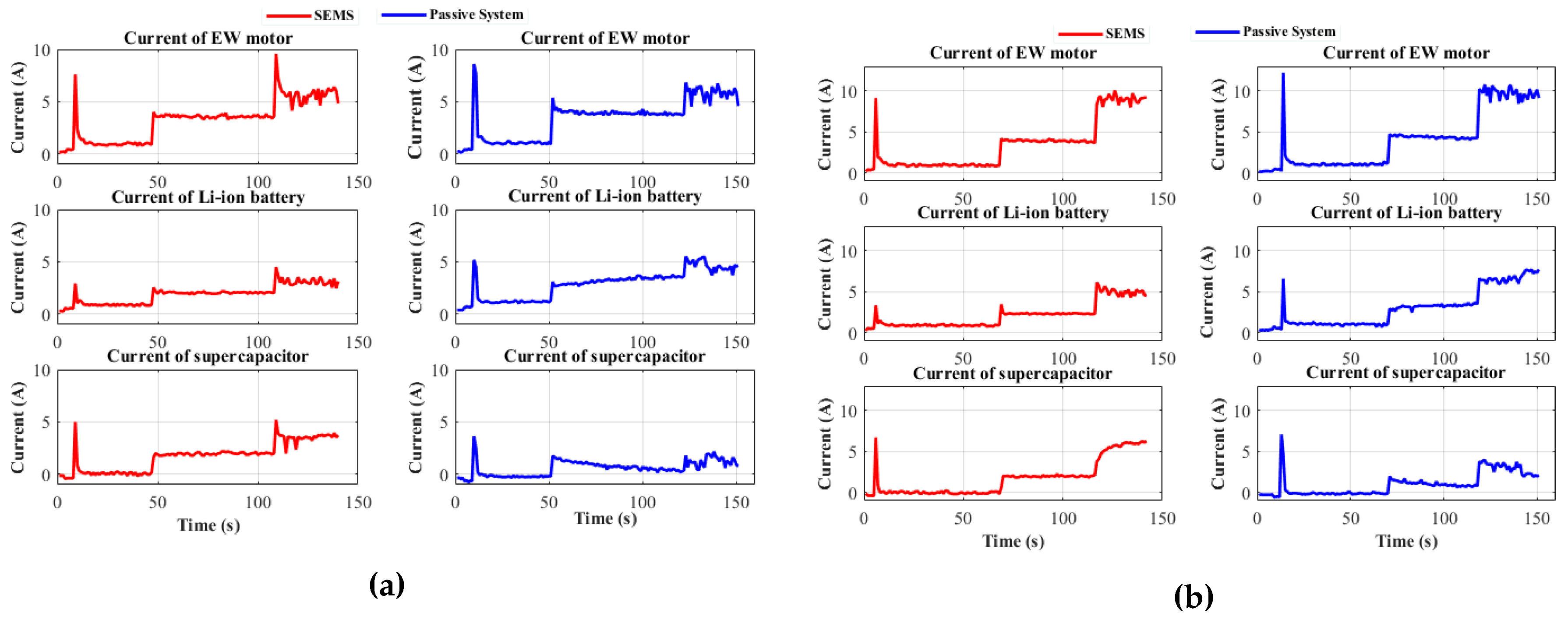
4.2. Performance Evaluation of P-HESS

The same tests were performed on a P-HESS for track-ABCD. Figure 14 shows the experimental results of the P-HESS. At t = 11 s, the EW motor started, and an approximately 3.5-A current was supplied by the LIB and 3.1 A was supplied by the SC, as shown in the current profiles of the LIB and SC, respectively, in Figure 14. From t = 12 to 50 s, the passive system traveled on a flat surface. The EW motor drew an average of 1.9 A, which was supplied by the LIB, whereas the SC current was almost zero. From t = 51 to 101 s, when it started traveling on an inclined surface, it drew 4.5 A. The LIB and SC supplied 3- and 1.5-A currents, respectively. Similarly, at t = 101–150 s, the passive system traveling on an inclined surface required more current, which was again supplied by the LIB. The current profile of the EW motor increased from 5 to 6 A. The LIB current also increased from 4 to 5 A. The SC supplied 1 A, as shown in the graph of the current of a supercapacitor (Figure 14).

5. Discussion

To validate the proposed technique, several experiments were performed to compare the result of SA-HESS and P-HESS under different conditions. The average current values of different track experiments are presented in Figure 15. It can be noted that by adopting the proposed technique, the stress of the LIB was reduced. In high-power-demanding conditions, the proposed technique effectively used the SC as compared with P-HESS to enhance the lifecycle of the LIB. Some of the results of real-time testing under different tracks are shown in Figure A1 of Appendix A.
The validation of the proposed system was also done under different load conditions. Figure 16 shows some of the experimental results of the proposed system and the P-HESS under different loading conditions. The superiority of the proposed algorithm under different loading conditions can be seen in Figure 16. The efficiency of the SA-HESS was 97.6% in the EW application. The proposed methodology does not have any significant effect on the cost of the system.
Renewable energy resources can be used to charge the HESS. The installation of a regenerative braking system in EWs is a good option to charge the SC during the downslope. The discharging efficiency of the HESS can be enhanced by using a smart controller such as an FLC.

6. Conclusions

This paper introduced a new hybrid energy management system for EWs. The SA-HESS was implemented using a smart energy management system algorithm. The proposed system ensured effective use of the SC and decreased the stress of the LIB to extend the battery life under demanding conditions. Five different tracks and two different loads were used to ensure the practicability of the proposed hybrid energy management system and to compare it with the passive system. The experimental results confirmed that the proposed system provided a more effective charging and discharging management system at high power demand compared with the conventional P-HESS.

Author Contributions

Conceptualization, S.H., M.U.A., and H.-J.K.; Formal analysis, S.H., S.H.N., and M.I.; Funding acquisition, H.-J.K.; Investigation, S.H.; Methodology, S.H. and M.U.A.; Software, M.U.A. and I.K.; Supervision, H.-J.K.; Validation, M.U.A., S.H.N., and M.I.; Writing—original draft, S.H., S.H.N., and I.K.; Writing—review & editing, H.-J.K.

Funding

This research was supported by Brain Korea 21 Center for Creative Human Resource Development Program for IT Convergence of Pusan National University.

Acknowledgments

This research was supported by Brain Korea 21 Center for Creative Human Resource Development Program for IT Convergence of Pusan National University.

Conflicts of Interest

The authors declare no conflict of interests.

Appendix A

Figure A1 shows the current profiles of the proposed system and P-HESS while traveling in different surface conditions.
Figure A1. Comparison of the proposed SEMS and P-HESS during different modes: (a) start–high climbing–low climbing–plain; (b) start–low climbing–plain–high climbing; (c) start–low climbing–high climbing–plain; (d) start–plain–high climbing–low climbing.
Electronics 08 00345 g0a1

References

  1. Tian, Z.; Xu, W. Electric wheelchair controller based on parameter self-adjusting fuzzy PID. In Proceedings of the International Conference on Computational Intelligence and Natural Computing, CINC’09, Wuhan, China, 6–7 June 2009; pp. 358–361. [Google Scholar]
  2. Yang, Y.-P.; Guan, R.-M.; Huang, Y.-M. Hybrid fuel cell powertrain for a powered wheelchair driven by rim motors. J. Power Sources 2012, 212, 192–204. [Google Scholar] [CrossRef]
  3. Khan, M.A.; Zeb, K.; Sathishkumar, P.; Ali, M.U.; Uddin, W.; Hussain, S.; Ishfaq, M.; Khan, I.; Cho, H.-G.; Kim, H.-J. A Novel Supercapacitor/Lithium-Ion Hybrid Energy System with a Fuzzy Logic-Controlled Fast Charging and Intelligent Energy Management System. Electronics 2018, 7, 63. [Google Scholar] [CrossRef]
  4. Cooper, R.A.; Cooper, R.; Boninger, M.L. Trends and issues in wheelchair technologies. Assist. Technol. 2008, 20, 61–72. [Google Scholar] [CrossRef] [PubMed]
  5. Cortés, U.; Annicchiarico, R.; Vázquez-Salceda, J.; Urdiales, C.; Cañamero, L.; López, M.; Sànchez-Marrè, M.; Caltagirone, C. Assistive technologies for the disabled and for the new generation of senior citizens: The e-Tools architecture. AI Commun. 2003, 16, 193–207. [Google Scholar]
  6. Cano, Z.P.; Banham, D.; Ye, S.; Hintennach, A.; Lu, J.; Fowler, M.; Chen, Z. Batteries and fuel cells for emerging electric vehicle markets. Nat. Energy 2018, 3, 279. [Google Scholar] [CrossRef]
  7. Ding, D.; Cooper, R.A. Electric powered wheelchairs. IEEE Control Syst. Mag. 2005, 25, 22–34. [Google Scholar]
  8. Ding, Y.; Cano, Z.P.; Yu, A.; Lu, J.; Chen, Z. Automotive Li-Ion Batteries: Current Status and Future Perspectives. Electrochem. Energy Rev. 2019, 2, 1–28. [Google Scholar] [CrossRef]
  9. Kim, T.; Song, W.; Son, D.-Y.; Ono, L.K.; Qi, Y. Lithium-ion batteries: Outlook on present, future, and hybridized technologies. J. Mater. Chem. A 2019, 7, 2942–2964. [Google Scholar] [CrossRef]
  10. Hussain Nengroo, S.; Ali, M.U.; Zafar, A.; Hussain, S.; Murtaza, T.; Junaid Alvi, M.; Raghavendra, K.V.G.; Jee Kim, H. An Optimized Methodology for a Hybrid Photo-Voltaic and Energy Storage System Connected to a Low-Voltage Grid. Electronics 2019, 8, 176. [Google Scholar] [CrossRef]
  11. Ren, G.; Ma, G.; Cong, N. Review of electrical energy storage system for vehicular applications. Renew. Sustain. Energy Rev. 2015, 41, 225–236. [Google Scholar] [CrossRef]
  12. Hussain Nengroo, S.; Kamran, M.; Ali, M.U.; Kim, D.-H.; Kim, M.-S.; Hussain, A.; Kim, H. Dual battery storage system: An optimized strategy for the utilization of renewable photovoltaic energy in the United Kingdom. Electronics 2018, 7, 177. [Google Scholar] [CrossRef]
  13. Masih-Tehrani, M.; Ha’iri-Yazdi, M.-R.; Esfahanian, V.; Safaei, A. Optimum sizing and optimum energy management of a hybrid energy storage system for lithium battery life improvement. J. Power Sources 2013, 244, 2–10. [Google Scholar] [CrossRef]
  14. Ralon, P.; Taylor, M.; Ilas, A.; Diaz-Bone, H.; Kairies, K. Electricity Storage and Renewables: Costs and Markets to 2030; International Renewable Energy Agency: Abu Dhabi, UAE, 2017. [Google Scholar]
  15. Ali, M.U.; Zafar, A.; Hussain Nengroo, S.; Hussain, S.; Alvi, M.J.; Kim, H.-J. Towards a Smarter Battery Management System for Electric Vehicle Applications: A Critical Review of Lithium-Ion Battery State of Charge Estimation. Energies 2019, 12, 446. [Google Scholar] [CrossRef]
  16. Gao, L.; Dougal, R.A.; Liu, S. Power enhancement of an actively controlled battery/ultracapacitor hybrid. Ieee Trans. Power Electron. 2005, 20, 236–243. [Google Scholar] [CrossRef]
  17. Di Napoli, A.; Ndokaj, A. Auxiliary power buffer based on ultracapacitors. In Proceedings of the 2012 International Symposium on Power Electronics, Electrical Drives, Automation and Motion (SPEEDAM), Sorrento, Italy, 20–22 June 2012; pp. 759–763. [Google Scholar]
  18. Yin, H.; Zhao, C.; Li, M.; Ma, C. Utility function-based real-time control of a battery ultracapacitor hybrid energy system. IEEE Trans. Ind. Inform. 2015, 11, 220–231. [Google Scholar] [CrossRef]
  19. Hochgraf, C.G.; Basco, J.K.; Bohn, T.P.; Bloom, I. Effect of ultracapacitor-modified PHEV protocol on performance degradation in lithium-ion cells. J. Power Sources 2014, 246, 965–969. [Google Scholar] [CrossRef]
  20. Zimmermann, T.; Keil, P.; Hofmann, M.; Horsche, M.F.; Pichlmaier, S.; Jossen, A. Review of system topologies for hybrid electrical energy storage systems. J. Energy Storage 2016, 8, 78–90. [Google Scholar] [CrossRef]
  21. Miller, J.M. Energy storage technology markets and application’s: Ultracapacitors in combination with lithium-ion. In Proceedings of the 7th Internatonal Conference on Power Electronics, ICPE’07, Daegu, Korea, 22–26 October 2007; pp. 16–22. [Google Scholar]
  22. Erdinc, O.; Vural, B.; Uzunoglu, M. A wavelet-fuzzy logic based energy management strategy for a fuel cell/battery/ultra-capacitor hybrid vehicular power system. J. Power Sources 2009, 194, 369–380. [Google Scholar] [CrossRef]
  23. Zhang, Q.; Deng, W. An Adaptive Energy Management System for Electric Vehicles Based on Driving Cycle Identification and Wavelet Transform. Energies 2016, 9, 341. [Google Scholar] [CrossRef]
  24. Xiong, R.; Chen, H.; Wang, C.; Sun, F. Towards a smarter hybrid energy storage system based on battery and ultracapacitor-A critical review on topology and energy management. J. Clean. Prod. 2018, 202, 1228–1240. [Google Scholar] [CrossRef]
  25. Kuperman, A.; Aharon, I. Battery–ultracapacitor hybrids for pulsed current loads: A review. Renew. Sustain. Energy Rev. 2011, 15, 981–992. [Google Scholar] [CrossRef]
  26. Dougal, R.A.; Liu, S.; White, R.E. Power and life extension of battery-ultracapacitor hybrids. IEEE Trans. Compon. Packag. Technol. 2002, 25, 120–131. [Google Scholar] [CrossRef]
  27. Chen, Z. High pulse power system through engineering battery-capacitor combination. In Proceedings of the (IECEC) 35th Intersociety Energy Conversion Engineering Conference and Exhibit, Las Vegas, NV, USA, 24–28 July 2000; pp. 752–755. [Google Scholar]
  28. Miller, J. Battery-capacitor power source for digital communication applications: Simulations using advanced electrochemical capacitors. Electrochem. Soc. Proc. 1995, 29–95, 246–254. [Google Scholar]
  29. Tie, S.F.; Tan, C.W. A review of energy sources and energy management system in electric vehicles. Renew. Sustain. Energy Rev. 2013, 20, 82–102. [Google Scholar] [CrossRef]
  30. Ju, F.; Zhang, Q.; Deng, W.; Li, J. Review of structures and control of battery-supercapacitor hybrid energy storage system for electric vehicles. In Proceedings of the 2014 IEEE International Conference on Automation Science and Engineering (CASE), Taipei, Taiwan, 18–22 August 2014; pp. 143–148. [Google Scholar]
  31. Song, Z.; Hofmann, H.; Li, J.; Han, X.; Zhang, X.; Ouyang, M. A comparison study of different semi-active hybrid energy storage system topologies for electric vehicles. J. Power Sources 2015, 274, 400–411. [Google Scholar] [CrossRef]
  32. Cope, R.C.; Podrazhansky, Y. The art of battery charging. In Proceedings of the Fourteenth Annual Battery Conference on Applications and Advances, Long Beach, CA, USA, 12–15 January 1999; pp. 233–235. [Google Scholar]
  33. Ali, M.U.; Kamran, M.; Kumar, P.; Hussain Nengroo, S.; Khan, M.; Hussain, A.; Kim, H.-J. An Online Data-Driven Model Identification and Adaptive State of Charge Estimation Approach for Lithium-ion-Batteries Using the Lagrange Multiplier Method. Energies 2018, 11, 2940. [Google Scholar] [CrossRef]
  34. Hussein, A.A.-H.; Batarseh, I. A review of charging algorithms for nickel and lithium battery chargers. IEEE Trans. Veh. Technol. 2011, 60, 830–838. [Google Scholar] [CrossRef]
  35. Tsang, K.; Chan, W. Current sensorless quick charger for lithium-ion batteries. Energy Convers. Manag. 2011, 52, 1593–1595. [Google Scholar] [CrossRef]
  36. Wei, Z.; Meng, S.; Xiong, B.; Ji, D.; Tseng, K.J. Enhanced online model identification and state of charge estimation for lithium-ion battery with a FBCRLS based observer. Appl. Energy 2016, 181, 332–341. [Google Scholar] [CrossRef]
  37. Wei, Z.; Zou, C.; Leng, F.; Soong, B.H.; Tseng, K.-J. Online model identification and state-of-charge estimate for lithium-ion battery with a recursive total least squares-based observer. IEEE Trans. Ind. Electron. 2018, 65, 1336–1346. [Google Scholar] [CrossRef]
  38. Wei, Z.; Zhao, J.; Ji, D.; Tseng, K.J. A multi-timescale estimator for battery state of charge and capacity dual estimation based on an online identified model. Appl. Energy 2017, 204, 1264–1274. [Google Scholar] [CrossRef]
  39. Pay, S.; Baghzouz, Y. Effectiveness of battery-supercapacitor combination in electric vehicles. In Proceedings of the 2003 IEEE Bologna Power Tech Conference Proceedings, Bologna, Italy, 23–26 June 2003; Volume 3, p. 6. [Google Scholar]
  40. Rashid, M. Power Electronics Circuits, Devices, and Application; Ptrentice-Hall International Inc.: London, UK, 1993. [Google Scholar]
  41. Huang, J.-W.; Liu, Y.-H.; Wang, S.-C.; Yang, Z.-Z. Fuzzy-control-based five-step Li-ion battery charger. In Proceedings of the International Conference on Power Electronics and Drive Systems (PEDS 2009), Taipei, Taiwan, 3–6 November 2009; pp. 1547–1551. [Google Scholar]
  42. Wangsupphaphol, A.; Idris, N.; Jusoh, A.; Muhamad, N.; Yao, L.W. The energy management control strategy for electric vehicle applications. In Proceedings of the 2014 International Conference and Utility Exhibition on Green Energy for Sustainable Development (ICUE), Pattaya City, Thailand, 19–21 March 2014; pp. 1–5. [Google Scholar]
  43. Ortúzar, M.; Moreno, J.; Dixon, J. Ultracapacitor-based auxiliary energy system for an electric vehicle: Implementation and evaluation. IEEE Trans. Ind. Electron. 2007, 54, 2147–2156. [Google Scholar] [CrossRef]
  44. Cui, X.; Shen, W.; Zhang, Y.; Hu, C. A Fast Multi-Switched Inductor Balancing System Based on a Fuzzy Logic Controller for Lithium-Ion Battery Packs in Electric Vehicles. Energies 2017, 10, 1034. [Google Scholar] [CrossRef]
  45. Ali, M.U.; Hussain Nengroo, S.; Adil Khan, M.; Zeb, K.; Ahmad Kamran, M.; Kim, H.-J. A real-time simulink interfaced fast-charging methodology of lithium-ion batteries under temperature feedback with fuzzy logic control. Energies 2018, 11, 1122. [Google Scholar]
  46. Azizi, I.; Radjeai, H. A new strategy for battery and supercapacitor energy management for an urban electric vehicle. Electr. Eng. 2018, 100, 667–676. [Google Scholar] [CrossRef]
  47. Hybrid Wheelchair. Available online: https://mafiadoc.com/hybrid-wheelchair_59c3e8f11723dd285cbc616e.html (accessed on 9 January 2019).
  48. Tammineedi, C. Modeling Battery-Ultracapacitor Hybrid Systems for Solar and Wind Applications. Master’s Dessertation, The Pennsylvania State University Graduate School, State College, PA, USA, 2011. [Google Scholar]
Figure 1. Comparison of different battery storage systems [14,15].
Electronics 08 00345 g001
Figure 2. Overview of the proposed methodology. Battery voltage (VBat), controlled current (Icontrolled), battery temperature (Tbat), lithium-ion battery (LIB), electric wheelchair (EW), pulse width modulation (PWM) and supercapacitor (SC).
Electronics 08 00345 g002
Figure 3. Flowchart for temperature control.
Electronics 08 00345 g003
Figure 4. The logic for the smart energy management system (SEMS): (a) normal plaint track-AB; (b) uphill climbing steep track-ABCD.
Electronics 08 00345 g004
Figure 5. Algorithm for the SEMS.
Electronics 08 00345 g005
Figure 6. Hardware implementation of the SEMS algorithm.
Electronics 08 00345 g006
Figure 7. Experimental setup of the prototype.
Electronics 08 00345 g007
Figure 8. Voltage and temperature profile of the Li-ion battery (LIB).
Electronics 08 00345 g008
Figure 9. Experimental results of the SEMS on the electric wheelchair (EW) motor.
Electronics 08 00345 g009
Figure 10. The experimental results at the start of the EW movement.
Electronics 08 00345 g010
Figure 11. Experimental results for track-AB.
Electronics 08 00345 g011
Figure 12. Experimental results for track-ABCD (points B–C).
Electronics 08 00345 g012
Figure 13. Experimental results for track-ABCD (points C–D).
Electronics 08 00345 g013
Figure 14. Experimental results of the passive hybrid energy storage system (P-HESS).
Electronics 08 00345 g014
Figure 15. Comparison of the proposed semiactive (SA)-HESS and P-HESS.
Electronics 08 00345 g015
Figure 16. Comparison of the proposed SA-HESS and P-HESS during different loads: (a) 35-W load; (b) 25-W load.
Electronics 08 00345 g016

