1. Introduction
Differential phase shifters (DPSs) are common components in many applications where a fixed phase difference is required between two points within a circuit. The applications include phase discriminators, beam forming networks, power dividers and phase array antennas. Typically, 90° or 180° DPSs are needed in most communication systems but, in general, any phase difference may be required for a specific application and therefore DPSs with arbitrary phase shifts and stringent performances are still of importance for microwave designers. Moreover, a parametric design procedure that enables one to obtain a full-band and high return loss DPS with minimum insertion loss for any phase difference, with respect to a reference line with the same physical length, is of great interest and provides improved flexibility in waveguide system architectures.
Many different technologies have been developed through the years for obtaining a differential phase shift within a circuit. This work deals with ridge waveguide-based DPSs because the structures based on planar circuits, such as microstrip technology [
1], despite having a compact size, exhibit noticeable insertion loss and low power handling capabilities that hinder their utilization in many antenna feed networks. Substrate integrated waveguide (SIW) technology has emerged as an option for combining advantages from planar technology, such as compactness and low cost, and waveguide technology, such as high quality factors and low insertion loss. Different DPS structures have been proposed in SIW technology in recent years [
2,
3] that attempt to conjugate all these advantages. However, hollow waveguide technology remains the best option for feed networks where the electrical requirements in terms of insertion loss, power handling capabilities, performance repeatability and mechanical rigidity, are of utmost importance. Achievement of the desired phase difference in a waveguide is generally obtained through variation of the waveguide propagation constant in the shift line. One way to do this is to modify the dielectric constant with the introduction of dielectric slabs [
4] or ferrite materials [
5,
6]. These structures can be easily designed to get any arbitrary phase shift, but their insertion loss is increased with the dielectric constant accordingly. An alternative procedure to change the propagation constant is to vary the waveguide physical dimension. Thus, in [
7], the inclusion of a series of E-plane stubs enables one to obtain a DPS with excellent phase performance in a 17% bandwidth. Unfortunately, this configuration requires a reference line with a different physical length, which may affect the circuit symmetry and integration. The use of waveguide corrugations [
8,
9,
10] has demonstrated good electrical results in designs with up to 30–35% bandwidth. The combination of high return loss, small shift errors and large bandwidths in these structures requires a large number of corrugations, thus affecting the compactness and easy-machining concepts. Finally, metallic ridges synthetized with fins or pins following stepped or continuous profiles have emerged as the best solution for their electrical performance [
10,
11,
12,
13]. However, among these last DPSs, those implemented with pins or smoothed profiles are more challenging during their design stages and show a noticeable increase in mechanical complexity, resulting in higher costs. In a previous work [
14], a ridge-based DPS was presented with full-band (40%) coverage in Ku-band and 25 dB of return loss showing ±2.5° and ±3.5° shift errors for a 90°-DPS and 180°-DPS respectively. Although this structure, as presented in [
14], can be easily scaled to other frequency bands, it cannot be straightforwardly modified to meet other phase difference values unless the design process is restarted. Therefore, a parametric design that provides fitting equations for any desired phase shift is of great interest for DPS designers.
Focusing on the concepts of minimum physical length and the same number of matching steps for all phase difference values, in this paper we present a parametric study of a ridge-based differential phase shifter resulting in fitting equations that enable a fast and accurate design process for obtaining a DPS with any arbitrary phase difference between the shift and reference lines with equal physical lengths. Furthermore, the electrical performance exhibits full-band coverage (40% relative bandwidth) with, at least, 25-dB return loss and minimum insertion loss. All these characteristics are combined with an easy mechanization that facilitates frequency scaling and provides robustness against mechanical tolerances.
Section 2 details the design of a generic differential phase shifter providing suitable fitting equations and parameter values for all phase differences. Experimental validation of the two exemplary DPSs is given in
Section 3. Finally,
Section 4 presents some conclusions.
2. Differential Phase Shifter Design
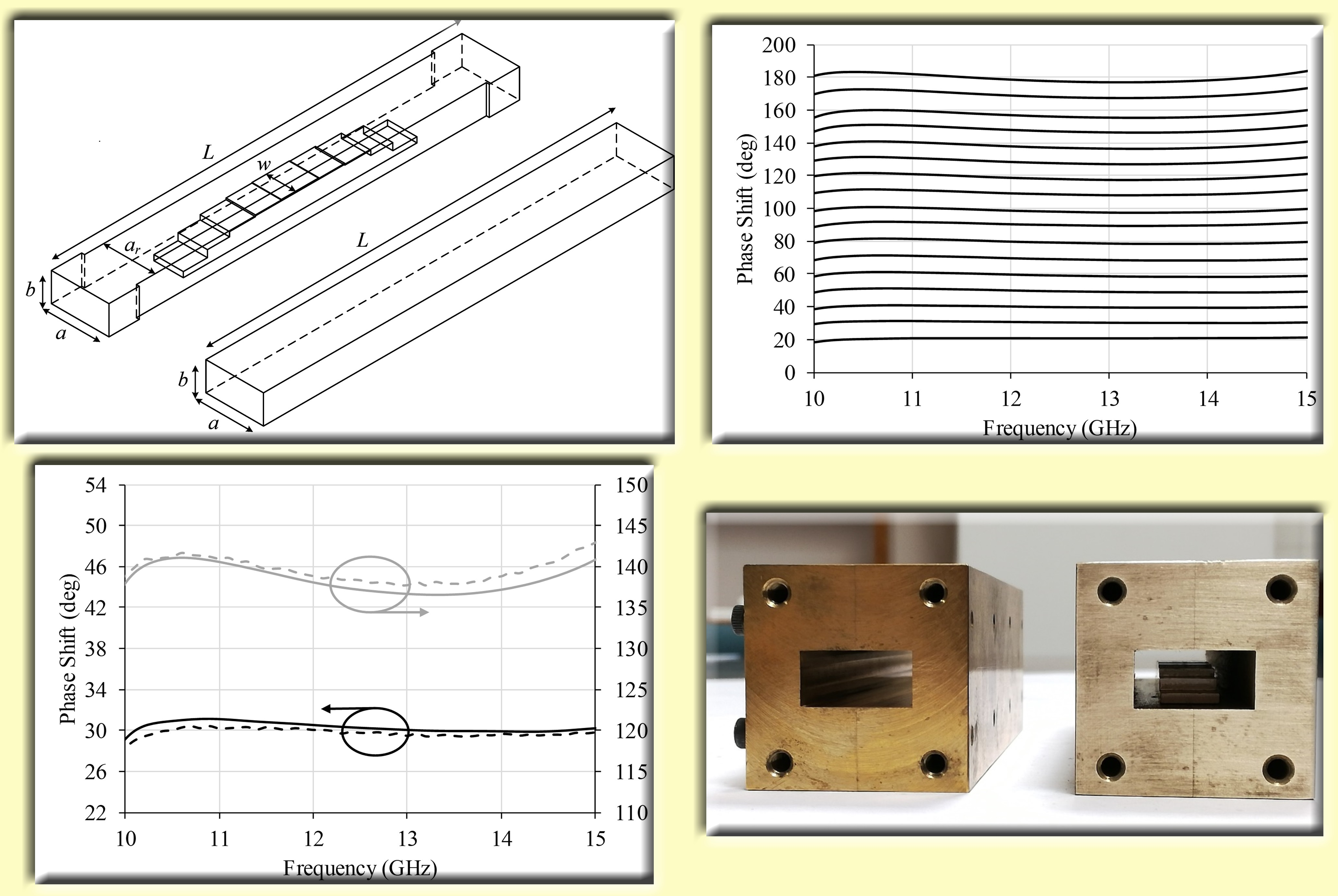
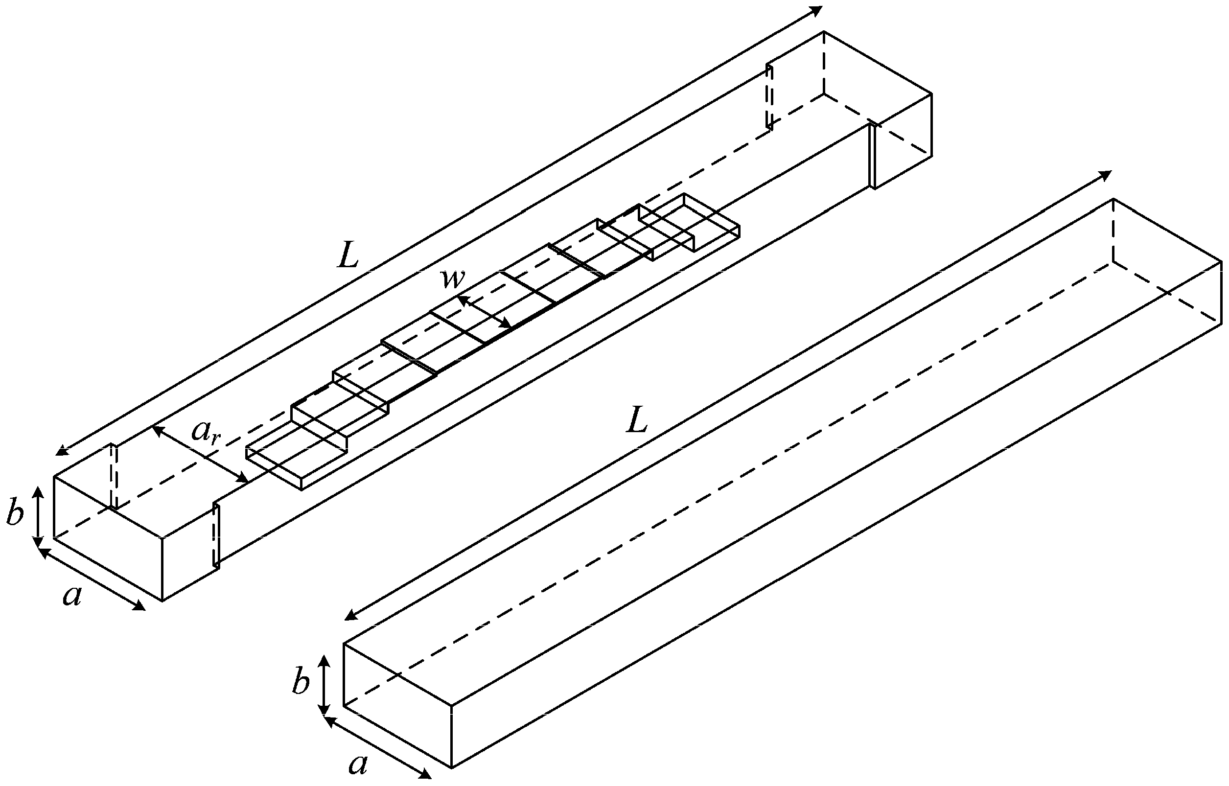
The ridge waveguide differential phase shifter used in the current parametric study follows the previously presented configuration in [
14], which is shown in
Figure 1 together with its reference line, an empty standard rectangular waveguide. As it is generally known, a ridge waveguide exhibits a wider mono-mode bandwidth than its empty waveguide counterpart due to the reduction of the fundamental mode cutoff frequency [
15]. On the other hand, the operational bandwidth of a DPS is commonly defined based on the acceptable phase shift deviation with respect to the desired phase difference. Depending on this shift accuracy, a DPS with the same electrical performance may show different bandwidths. Corrugation-based DPSs [
8,
9,
10] exhibit a quadratic-like phase difference curve that rapidly deviates from the desired phase value; however, ridge-based DPSs show a cubic-like curve, which widens the frequency range with controlled phase error. This feature, together with the aforementioned increased mono-mode bandwidth, clearly points at ridge DPS as the best solution for waveguide wideband applications.
Before starting the design process for a frequency range (40% relative bandwidth) defined by its lowest and upper frequencies (
f1 and
f2 respectively), some constraints have to be imposed on the structure, otherwise multiple sets of parameter values could be obtained for a determined electrical response, thus affecting the systematicity of this study. Firstly, in this work, the ridge thickness,
w in
Figure 1, has been fixed to the waveguide height value
b,
w =
b. Alternative and valid parameter values could be found, starting with another ridge thickness value. Secondly, the number of ridge matching steps has been set to
n = 4, whatever the phase difference desired value is. These matching steps perform two functions: on one side they introduce part of the final phase shift, and on the other side they act as impedance transformers that provide the DPS matching. The larger the number of matching steps the higher the return loss, at the expense of higher design and mechanization complexities. Finally, since the phase delay is a periodic function, the same phase shift can be achieved with different physical lengths, so therefore the design process is followed upon the premise of the minimum physical length of the DPS.
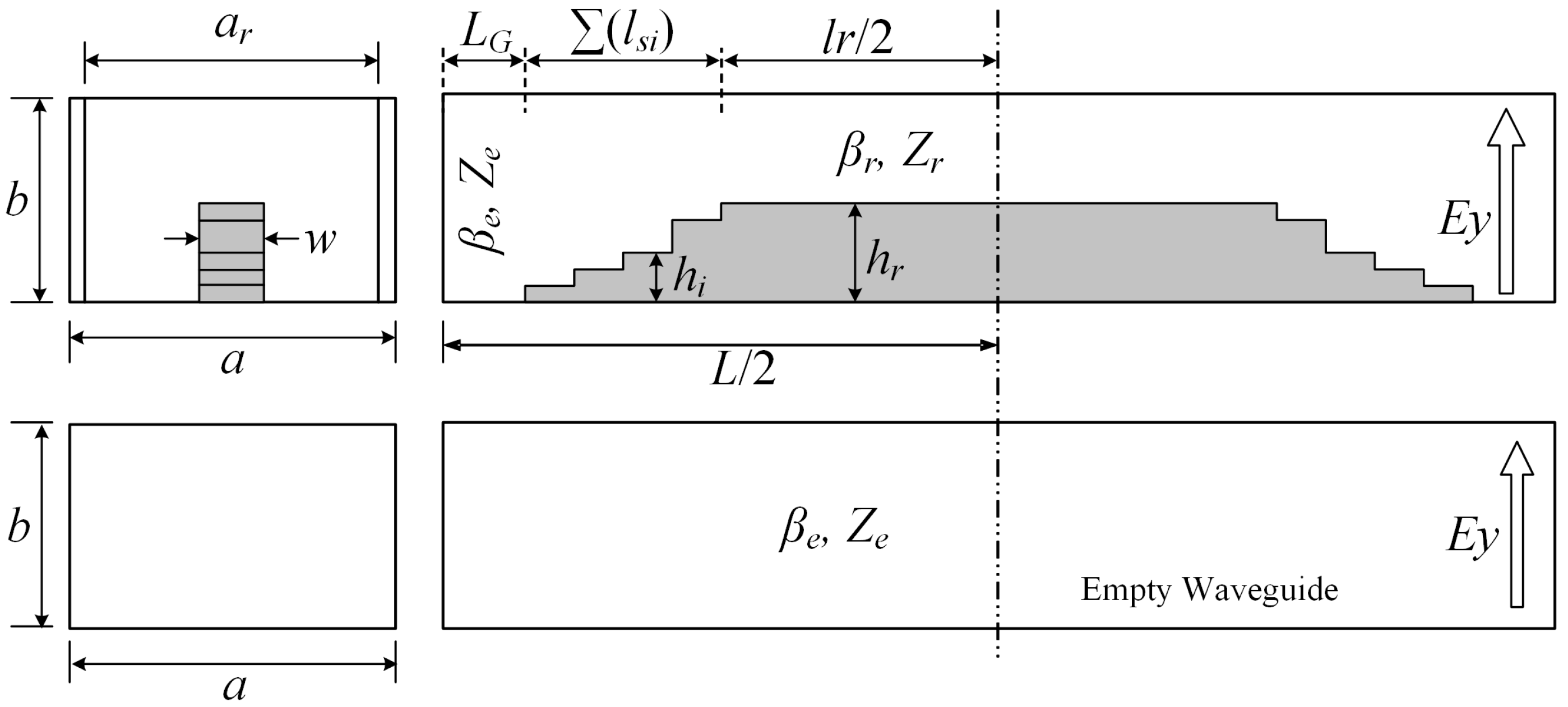
A simplified scheme of the DPS is shown in
Figure 2 together with the relevant physical and electrical parameters that are required for understanding the subsequent equations. The shift line is composed of two symmetric networks, each one made up of an initial empty section with dimensions
ar,
b and length
LG which is followed by
n = 4 matching steps, with dimensions
hi and
lsi,
i = 1 …
n, and finally, a ridge section with dimensions
hr and
lr/2. This structure is directly connected with the standard waveguide of dimensions
a and
b. The width step between
a and
ar is introduced to match the fundamental mode cutoff frequency between the empty and ridge waveguides.
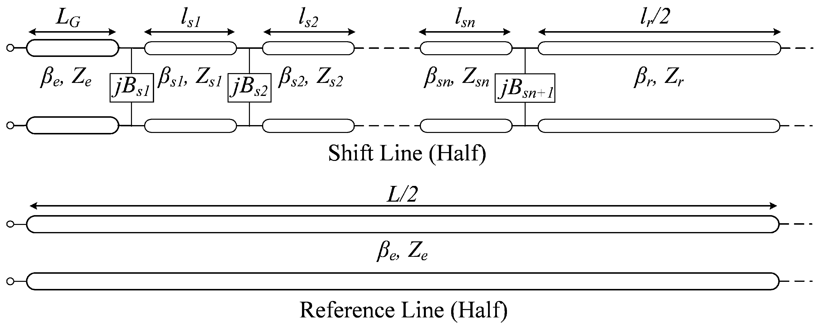
The previous scheme is modeled with an equivalent mono-mode circuit as shown in
Figure 3 (only one half). In this model, each step discontinuity corresponds to a shunt susceptance whose value is obtained from the generalized scattering matrix associated to this discontinuity by using the modal scattering analysis developed in [
11], and by extracting the values corresponding to the fundamental mode from the generalized scattering matrix. Additionally, rectangular and ridged waveguide sections can be modeled in the mono-mode approach by a simple dispersive transmission line where the characteristic admittances and propagation constants can be calculated from [
15]. In
Figure 3, the different step susceptances,
Bsi, propagation constants,
βsi and
βr, and waveguide impedances,
Zsi and
Zr, are the geometry-related design parameters with respect to an empty waveguide of the same length
L defined by
βe and
Ze.
With the parameters defined in
Figure 3, the ABCD matrix of half DPS can be established (1), and using this matrix it is feasible to obtain the overall input impedance (2) and voltage transfer ratio (3). From this last expression, the amplitude must be equal to the unity and the phase must be equal to the nominal phase shift value with respect to the reference waveguide, i.e., the desired phase difference between both waveguides. Once the different parameters have been calculated, these values are translated back to physical dimensions by using the mono-mode generalized scattering matrix method. Performing this procedure for selected phase difference values within the total range of possible phase shifts allows fitting curves for the physical parameters to be extracted in order to get useful tools that help in the design of DPSs with arbitrary phase shifts.
In order to perform a parametric study, in this work we calculated physical dimension values for phase shifts from 20° to 180° in 10° steps. Then, these values were fitted with 3rd-order polynomial equations as presented in (4), obtaining a fitting error of less than 2%. Coefficients of the fitting polynomials are given in
Table 1, where widths and heights are normalized to the standard waveguide dimensions
a and
b, respectively, and the lengths are normalized to
λg, where
λg is the empty waveguide wavelength at the center frequency,
f0 = (
f1 ×
f2)
1/2. Finally, the design parameters obtained from these equations are used as an initial guess for the mode-matching simulation tool µWave-Wizard from Mician GmbH. Minor optimization of the geometric dimensions in this tool is sufficient to meet the required specifications. The optimization process follows these guidelines: the desired bandwidth is firstly set, always aiming at a 40% relative bandwidth, and then all the mechanical dimensions are optimized trying to meet two main goals. These two goals are a return loss of 25 dB or better and achievement of the nominal phase shift with minimum phase error. Obviously, for each phase shift nominal value the phase error is different, increasing as the corresponding nominal value does.
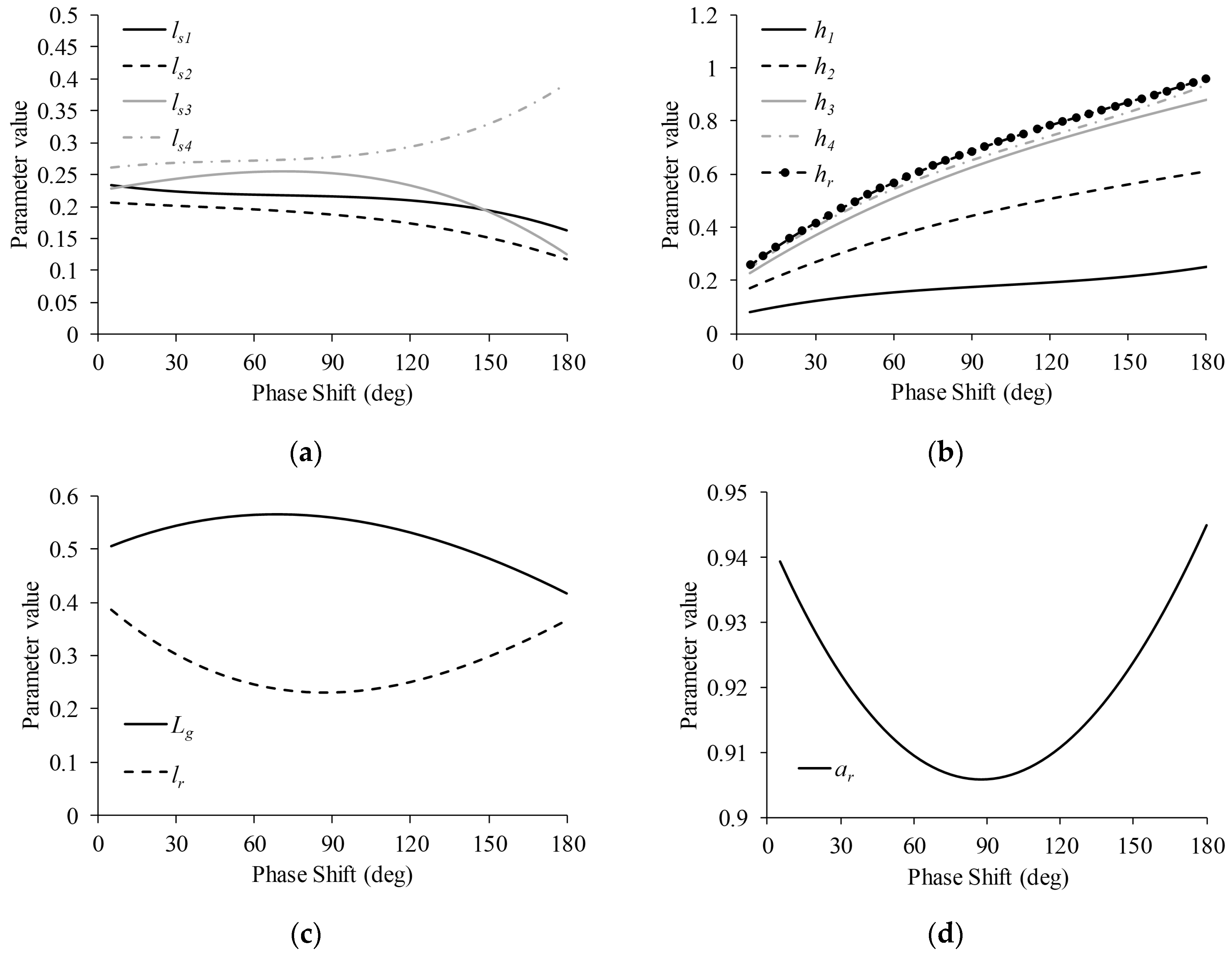
In (4), parameter
p stands for any DPS physical dimension as given in
Table 1 and
d is the desired broadband phase delay in degrees. Curves for all design parameters are plotted in
Figure 4.
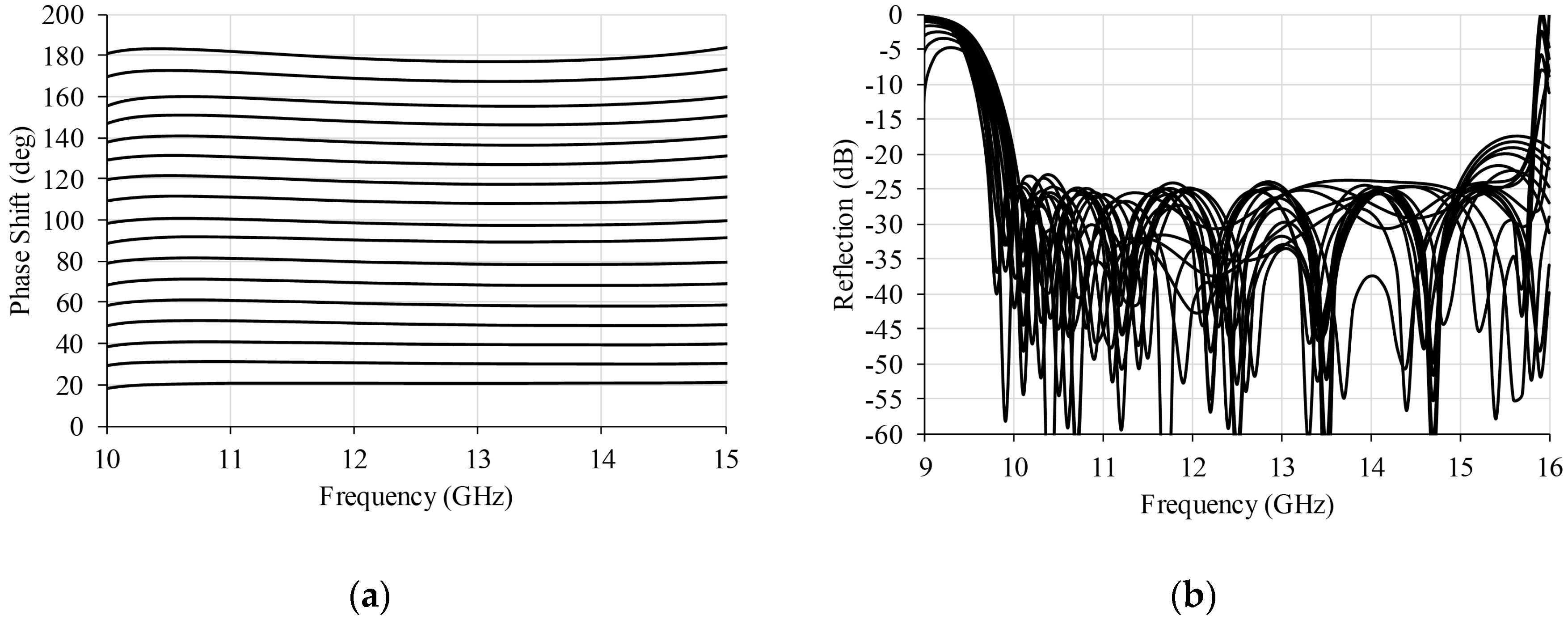
Following the previous equations, different DPSs for phase delays from 20° to 180° in 10° steps were designed in the 10–15 GHz frequency band. The corresponding electrical performances are presented in
Figure 5. As can be appreciated, all the designed DPSs have a return loss of 25 dB, whereas the phase errors range from ±0.5° for the 20°-DPS to ±3.1° for the 180°-DPS.
3. Experimental Verification
In order to experimentally validate the parametric design detailed in the previous section, two exemplary DPSs were designed and mechanized. From the available phase shift range, we selected the 30° and 140° units to provide two alternative configurations different from the classical 90°-DPS appearing in most published works. Notwithstanding the selected units, similar results could have been found with any other phase shift election as is demonstrated in
Figure 5. Final dimensions are given in
Table 2.
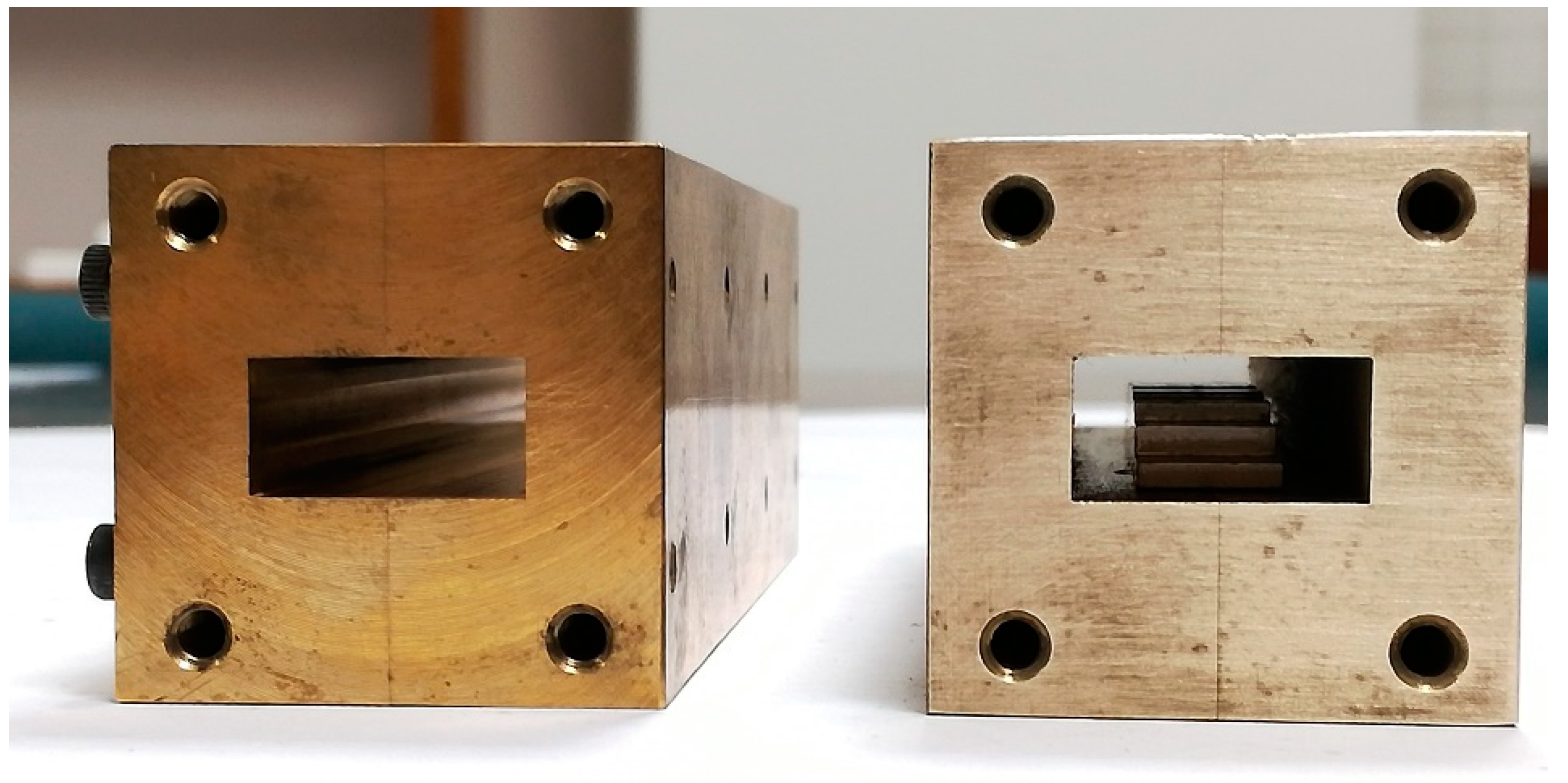
The DPSs were mechanized in two blocks of brass which are joined by the E-plane as shown in
Figure 6. Thus, insertion loss is minimized and rounds are avoided in the waveguide inner corners. The ridge is mechanized separately and then screwed on to the corresponding waveguide inner wall. This procedure, apart from facilitating its manufacture, enables one to implement small modifications to the ridge if necessary, and therefore to the DPS tuning.
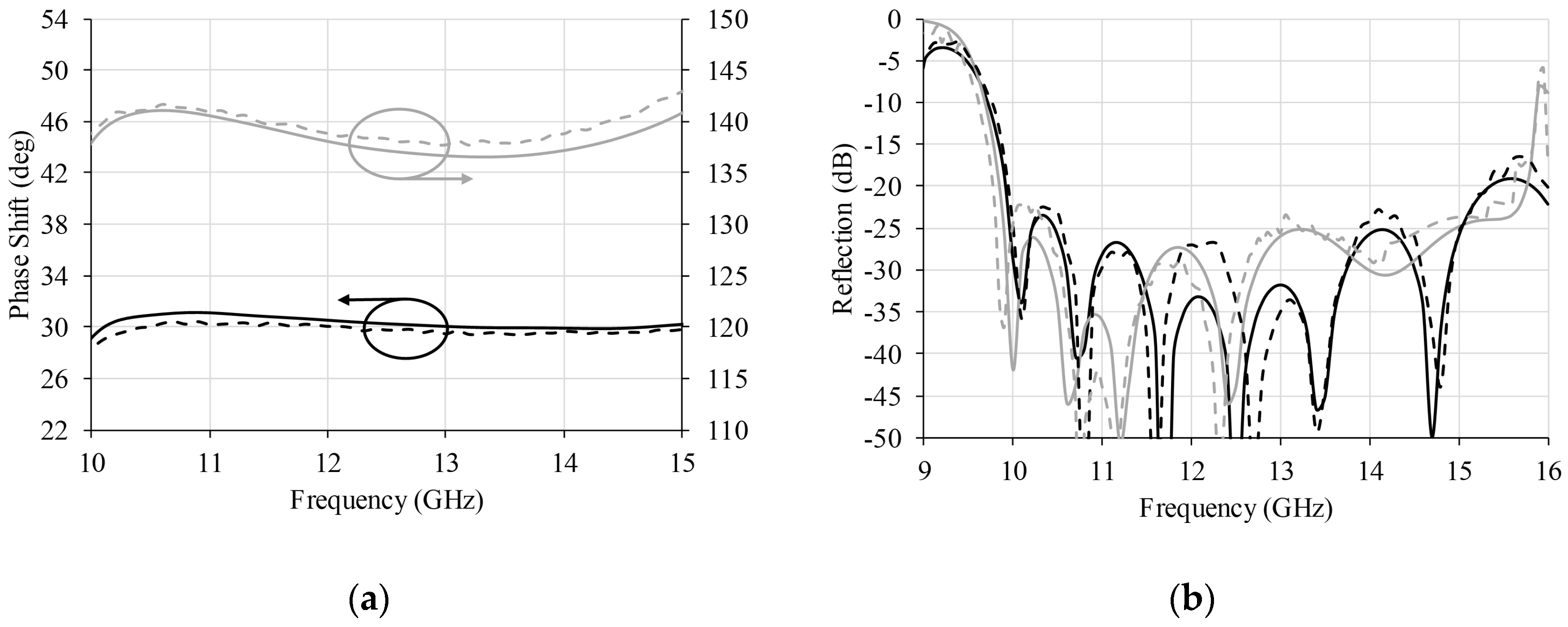
For the measurement, commercial coaxial-to-WR75 transitions are connected to the vector network analyzer (VNA) and the thru-reflect-line (TRL) calibration technique is applied at the WR75 ports. Therefore, the calibration plane is established at the DPSs ports and their performance is directly measured. For the phase shift measurement, the shift and reference lines are measured and the difference between the phases of their corresponding transmission coefficients is calculated. The obtained values are presented in
Figure 7 together with the simulated results for better comparison.
From plots in
Figure 7, a good agreement between simulation and theory can be appreciated, which validates the design procedure and the obtained fitting equations. Phase shift error is ±0.6° for the 30°-DPS and ±2.5° for the 140°-DPS, whereas the return loss is around 25 dB for both circuits in the 10–15 GHz frequency range. Small differences between simulated and measured results are attributed to mechanical tolerances.
Finally, results obtained in this work are compared in
Table 3 with other published waveguide DPSs following similar or alternative topologies in order to demonstrate its suitability. From these results, the advantage of ridge DPSs over corrugated DPSs is clear. Although these last structures are from square waveguide polarizers, corresponding DPSs could have been designed in rectangular waveguides. However, the length of these structures is noticeably greater than the ridge counterparts. On the other hand, stub loaded shifters tend to be shorter in length but in this case the shift line and its reference line are of different lengths, which produces symmetry issues during integration. Finally, ridge-based DPSs made with pins or smoothed-ridge profiles increase the mechanical complexity. The former show very limited electrical performance, whereas the latter achieve a very compact design at the expense of increasing the insertion loss. Differential phase shifters based on ferrites or dielectric slabs are omitted in
Table 3 due to its high losses.


