Review

Electrical Circuit Modelling of Double Layer Capacitors for Power Electronics and Energy Storage Applications: A Review

1
School of Electrical, Electronic and Computer Engineering, North-West University, Potchefstroom 2520, South Africa
2
Faculty of Engineering and Physical Sciences, Queen’s University Belfast, Belfast BT7 1NN, UK
*
Author to whom correspondence should be addressed.
Electronics 2018, 7(11), 268; https://doi.org/10.3390/electronics7110268
Submission received: 31 August 2018 / Revised: 18 October 2018 / Accepted: 19 October 2018 / Published: 23 October 2018
(This article belongs to the Special Issue Applications of Power Electronics)

Abstract

:
There has been increasing interests in the use of double layer capacitors (DLCs)—most commonly referred to as supercapacitors (SCs), ultra-capacitors (UCs), or hybrid capacitors (HCs)—in the field of power electronics. This increased interest in the hybridization of energy storages for automotive applications over the past few years is because of their advantage of high power density over traditional battery technologies. To facilitate accurate design and simulation of these systems, there is a need to make use of accurate and well validated models. Several models have been postulated in literature, however, these models have various limitations and strengths, ranging from the ease of use down to the complexity of characterization and parameter identification. The aim of this paper is to review and compare these models, specifically focusing on the models that predict the electrical characteristics of DLCs. The uniqueness of this review is that it focusses on the electrical circuit models of DLCs, highlighting the strengths and weaknesses of the different available models and the various areas for improvement.

1. Introduction

The effects and threats of global warming to the world have driven the increased development of high efficient and environmentally friendly alternative sources of energy for use. This has fueled the research into renewable energy sources for both domestic and industrial use [1,2,3,4,5,6,7,8,9]. Energy storage seems to be the biggest challenge in the advancement towards renewable energy solutions. Hybridization of energy storage has been the theme of many research studies in the field of power electronics and energy management [10,11,12,13,14,15,16,17,18,19,20,21,22,23], as it is considered to have great promise as an effective economic solution towards improving the performance of energy systems. Double layer capacitors (DLCs) have been proved to be very useful in hybridization of energy storages; this is due to their higher power density characteristics as compared to batteries [10,11,12,24].
DLCs are energy storage devices that use a double layer formed on a large surface of microporous material, such as activated carbon [25,26,27,28,29]. DLCs currently are of two major types, the supercapacitors (SCs) or ultra-capacitors (UCs) and the hybrid capacitors (HCs). The distinctive differences between the SCs and HCs is that the negative and positive electrode (anode and cathode, respectively) of the SCs are both made from activated carbon, whereas in the case of the HCs, the electrodes (either the cathode or anode, or both) are made from a lithium doped material—this results in the HCs having more energy density than the SCs [30,31]. This difference is illustrated in [32]; the HC’s chemistry exhibits a combination of the lithium-ion battery and a SC. However, in spite of the differences in their energy and power characteristics, it has been established that they both have the same electrical model and characterization method [30].
With the growing interest in the use of DLCs for power electronics and energy storage applications, power electronic designers and engineers are constantly faced with the vital task of accurately designing and selecting suitable DLCs for their applications. More often than not, the design process is carried out in a simulation environment using high fidelity computer software. However, in order to accurately simulate the electrical behavior of the components in a software environment, it is important to correctly use the electrical models of the components in order to get an accurate view of their electrical behavior in response to a load. Unfortunately, many models of DLCs exist in literature and choosing the right DLC model to use is an exhausting task. New designers in DLC design and selection for various applications will find the content of this paper very helpful, as it will bring them up to speed on the state of the art and what parameters are required for the use of any of the electrical models. This paper is unique because it focusses on the electrical applications and end use models rather than the models that focus on predicting chemical characteristics of the DLCs. Considering these factors, the timeliness and uniqueness of this review cannot be overemphasized. The goal of this paper is to review the many available electrical models of DLCs for power electronics applications in order to bring to light both their limitations and advantages, as well as the opportunities for further research into the subject of electrical modeling of DLCs. Additionally, this paper also seeks to raise awareness regarding the need for more research into the existing electrical models in order to address the limitations of these models, which are highlighted in this paper.
This paper is presented in the following order: the second section provides a brief history and an overview of the structure of DLCs, the third section reviews the modelling of conventional capacitors and presents the various double layer capacitor models, Section 3.8 compares all the models of the DLCs reviewed in order to bring to light their comparative advantages as well as their disadvantages. The conclusion and recommendations of this review paper are presented in the fourth section.

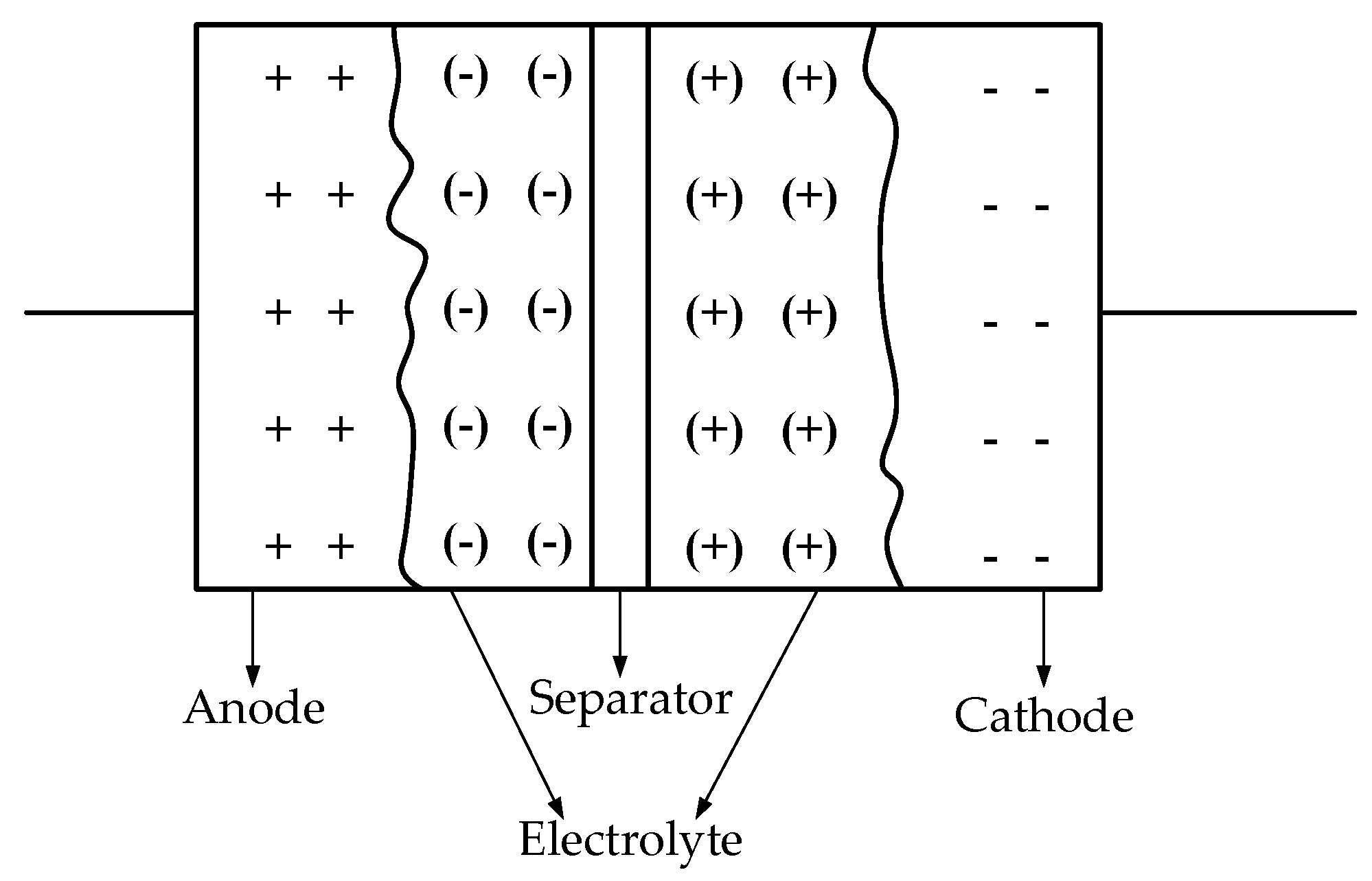
2. History and Structure of DLCs

The concept of double layer capacitance was first described by Hermann von Helmholtz, a German physicist, in 1853 [33]. One hundred and four years later, General Electric Company received the first patent of electrochemical capacitors based on the structure of double layer capacitance as described by Hermann von Helmholtz; their capacitor utilized porous carbon electrodes, using the double layer mechanism for charging [34]. In the same year, a Japanese company, Nippon Electric Company (NEC), received a license to use a technology that had been initially patented to Standard Oil; this technology was a device that stored energy in double layer interface. With this technology, the first market-ready electrochemical capacitors were produced for application in memory back-ups of computers in the same year, 1957 [35,36]. However, this was not a successful attempt until in 1971, when the same Japanese company, NEC, produced the SC, which then became the first commercially successful double layer capacitor [36,37]. Since then, the development of DLCs has been quite rapid. With improvements as the years went by, other companies, such as Maxwell technologies, Panasonic, Nesscap, AVX, Cap XX, Taiyo Yuden, Yunasko, etc., to mention just a few, have joined the race to push the frontiers of DLCs further.
The schematic construction of DLCs is shown in Figure 1. A DLC consists of three basic layers: the electrolyte, the separator, and the positive and negative electrodes. It exploits the double layer of charge formed when a voltage is applied to an electrode immersed in an electrolyte [38]; this is most likely where the name double layer capacitors originate.
The electrolyte and electrodes used in the construction of DLCs have to be selected interdependently, as these two largely directly affect the power and energy density of the capacitor cell. There are two types of electrolytes currently in use for DLCs and they are the aqueous and organic electrolytes. However, the organic electrolyte is most commonly used in commercial devices; this is because the organic electrolyte gives room for achieving higher voltages and very low self-discharge, and does not require chemical modification of the electrode [39]. There are various types of materials being used for the electrodes, such as metal-oxides, conducting polymer, and carbon, to mention just a few. However, carbon has been more commonly utilized because of its low cost and availability [36]. Different treatments of carbon are being researched for the improvements of the electrode, which has a direct impact on the power density of the cell [38,40]. The separator provides electrical isolation between the two electrodes; however, it is an ion-permeable membrane, giving room for ionic charge transfer between the two sections of the electrolyte. The materials used for the separator usually depend on the electrolyte used and they include polymer and paper for organic electrolytes and ceramic and glass fiber for aqueous electrolytes. More details on the structure and construction of DLCs can be found in Sharma and Bhatti [36], Signorelli et al. [38], and Yoshida et al. [40].
Currently, the two major DLCs are the electrochemical double layer capacitor (EDLC) and the HC. The EDLC, often referred to as a SC or UC, has both its positive and negative electrodes made from carbon. The most common HC is the lithium-ion capacitor (LiC); this is formed from the combination of the intercalation mechanism of a lithium ion battery with the cathode of an EDLC; the anode of the LiC is doped with a lithium ion, hence the name LiC. Other materials used for the electrodes of HCs include potassium-ion and other lithium-containing materials such as Li4Ti5O12, TiO2, LiMn2O4, and LiFePO4 [41]. The other type of DLC is the pseudo capacitor. Contrary to the EDLC and the HC, storage of charge is done faradically through the transfer of charge between the electrode and the electrolyte [42]. This faradic charge storage in pseudo-capacitors presents the potential for higher energy densities than the EDLCs. However, the low cycling stability and huge prohibitive costs have limited the successful adoption of pseudo-capacitors in the market [43].
The performance of energy storages in regards to their specific energy and power densities is usually compared using a graph called the Ragone plot. It consists of two axes, the energy density and power density axis. The different energy storage devices are then plotted on the graph according to their respective characteristics; with this, their performances can be easily compared at a glance. The Ragone plot presented in Figure 2 [44] shows the major differences between the LiC and the EDLC (also known as SC). The LiC has a much higher energy density than the SC, while the SC has a higher power density than the LiC.
The applications of DLCs are very wide and cannot be exhaustively discussed, as new applications are being introduced in research year in and year out. Their applications include, but are not limited to, the following: applications in memory backups of computing devices [45], energy storage hybridization in electric vehicles [46,47,48], applications in static synchronous compensators (STATCOMs) for improved power quality in power distribution systems [36,49,50].

3. Double Layer Capacitor Modelling

Before diving into the world of double layer capacitor modelling, it is important to briefly review some modelling methods of conventional capacitors. This will give a complete perspective when looking at the DLCs, since the basis for the double layer capacitor is the conventional capacitor.

3.1. Conventional Capacitor Modelling

Capacitors are usually modelled as lumped RLC (resistor-inductor-capacitor) networks, with the resistor representing the series resistance or ESR (equivalent series resistance) of the capacitor, the inductor representing the inductance of the capacitor leads and the current path through the capacitor, while the capacitor’s value is the rated capacitance of the capacitor being modelled. However, results from recent experiments indicate that the inductance or equivalent series inductance (ESL) in the lumped RLC models is quite inaccurate, and hence can be misleading [51].
Due to this fact, a more distributed model of capacitors is introduced by Sullivan et al. [51] in their research. This distributed model was derived in the form of a standard lumped transmission line model. Figure 3 describes the progression of the derivation of this distributed model from the standard lossless transmission line model in Figure 3a, through to the proposed distributed capacitor model. In the standard lossless lumped transmission line model, each individual capacitor plate pair is modelled as a discrete capacitor and then an inductance is added between these discrete capacitors. The inductance is calculated using Equation (1)
L =   μ o · ( x l w )
where µo is the permeability of free space, l is the length of the capacitor that is parallel to the current path, w is the width of the capacitor, and an assumption is made that w >> x, where x is the height.
However, although the standard lossless transmission line is the most basic distributed model of the capacitor, it does not match the behavior of actual capacitors in practical. This obviously is due to the fact that actual capacitors are not lossless. In Figure 3b, two resistors are introduced in the standard lossless transmission line model R’p, representing the leakage resistance, and R’s, which represents the vertical path along the end metallization of the capacitor. Both resistances are very small and are reported to have very little effect on matching the simulated results to the experimental results. The model is further tweaked in Figure 3c by introducing resistor R’D to model the dielectric losses and the metallization resistance on each plate. It is reported that this model gives a more closely related result in simulation to experiments when compared to the model in Figure 3b. A more improved model was developed and is as shown in Figure 3d. This model is obtained through comparison of the measured and simulated step-response results. In this model, inductor L’D is placed in parallel to resistor R’D. This was done to indicate a frequency dependence in the loss effects; this was based on the principle that losses in the ceramic dielectric increase rapidly with frequency.
In the same study, the authors introduced another capacitor model that was based on measurements of the dielectric characteristics in the frequency domain as opposed to just matching the overall step response of the system, as was done in the model presented in Figure 4. Although a great improvement was reportedly achieved by using both models proposed by the authors when compared with the lumped RLC model, the distributed models still show a significant difference between the simulated and experimental data. The authors suggest that a more comprehensive model of the eddy current losses could match the actual behavior of the capacitor. The authors report that their models fit better to experimental data when compared to the alternatives, although their models still need to be refined further to fully capture the actual behavior of capacitors. There are two major problems with the models proposed by the authors. Firstly, the models have only been validated for one type of capacitor. Secondly, there is no specific number of lumped sections that is satisfactory to obtain best results; this would make the research quite difficult to replicate in simulation.
In another study by Perisse et al. [52], two models were developed for electrolytic capacitors taking into account the temperature and aging of the capacitors. Their motivation was that since in many applications of the electrolytic capacitors, such as transport and aerospace engineering, the degrading characteristics and temperature variations become significant with time, a model taking these degrading characteristics into consideration is very important. Figure 5 presents the two models that were used. The parameter identification was carried out using a genetic algorithm integrated into Matlab®, and this was done also using the frequency data measurements. In Figure 5a, C1, represents the total capacitance between the anode and the cathode. Resistance Ra is a combination of a number of terms, which include the resistances of the terminals, the tabs, the foils, the impregnated electrolyte paper, the tunnel electrolyte, and the dielectric. Rc is the leakage current, which is dependent on the quality of the dielectric material. Rb was not stated to represent anything but was reported to be essential in obtaining a physical representation of the model, even though it did not have much influence in the range of measurement.
Capacitor C2 and resistors R2a and R2c were added in Figure 5b in order to factor in the effect of temperature reduction so as to obtain better results throughout the temperature range, especially for negative temperatures. The exact method of their parameter identification and characterization is detailed in the study by Perisse et al. [52]. It is important to state that although the results reported by the authors are positive, the models have been validated for only electrolytic capacitors, therefore they cannot be applied to other capacitor types unless further research is carried out to validate the model for other capacitor types.
Looking at these four capacitor models, it can be said that the lumped RLC circuit model is still the simplest and most basic model for conventional capacitors, since other more detailed models fall short in their validations and simulations. Now that we have established the background of conventional capacitors, the next few subsections will focus on modelling of DLCs.

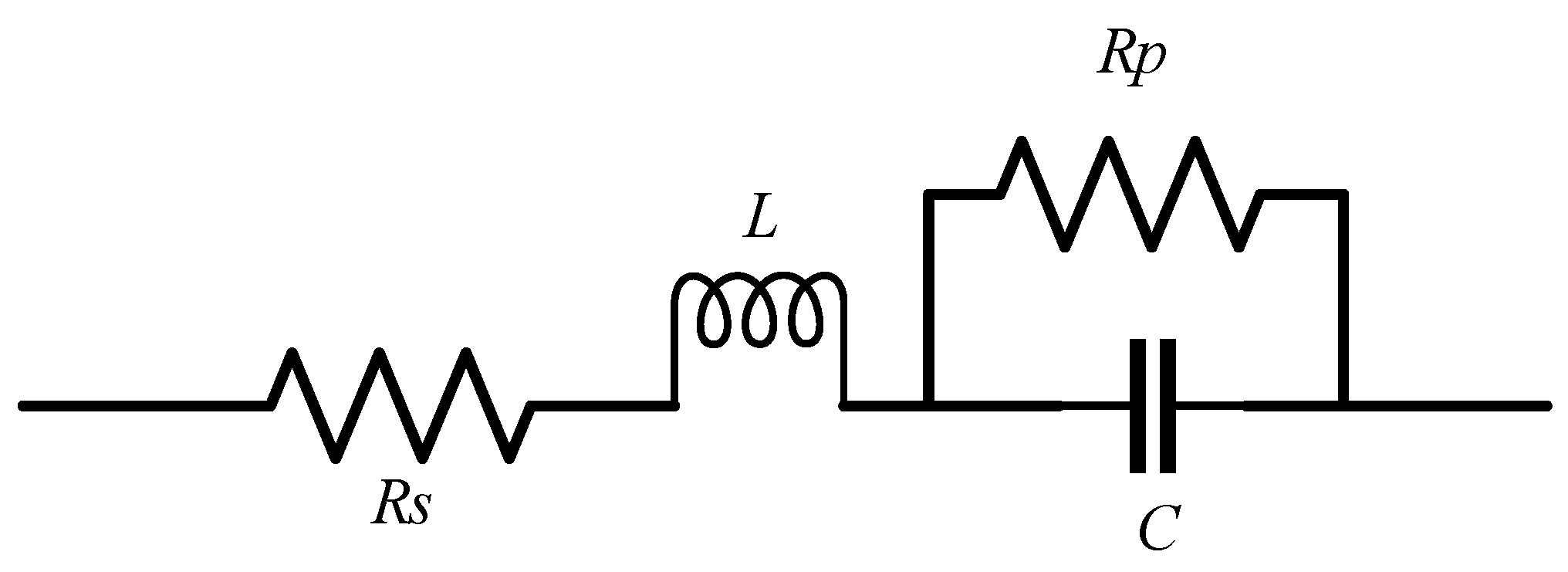
3.2. Classical Equivalent Circuit Model

The classical equivalent circuit model of DLCs is the most common, simplest, and probably the most basic model of a double layer capacitor [53]. This model is represented in Figure 6 [25]. It consists of just three parameters: a capacitor (C), a series resistance R, and a parallel resistance (Rp). The three circuit parameters can be obtained from the datasheet of the manufacturers of the devices. Ri is the equivalent series resistance, C is the rated capacitance of the device, and Rp is calculated by dividing the nominal voltage by the leakage current, which are both presented in the datasheets of the manufacturers.
The ease of parameter identification for the classical equivalent circuit model makes it very easy to implement in simulation. The classical equivalent model has been validated to have a closely relatable response to the actual response of a physical model [53,54]. However, in his research, Rodolfo [55] came to the conclusion that the classical equivalent circuit model does not perfectly match the behavior of DLCs as compared to other electrical models. Therefore, for basic simulation studies the classical equivalent circuit model can be used, especially in preliminary design calculations.
Cultura and Salameh [56] suggest that for short duration experiments, the classical equivalent circuit model can be further reduced by removing the leakage resistance, thereby reducing the model to just the equivalent series resistance and the capacitance of the DLC. This is because the leakage resistance is much larger than the series resistance, therefore it has no significant effect on the performance of the model for an analysis lasting for a short duration. Another derivation from the classical equivalent circuit model was done by Nakajo et al. [57]. The authors replaced the capacitance C in the classical equivalent circuit model with a variable capacitor. The capacitance was varied depending on the discharge current through a lookup table. The model was validated with a 200 F Lithium-ion capacitor and the results obtained were reported to be impressively above 98% correlation for both charging and discharging of the DLC.
A slight deviation from the classical equivalent circuit model is the first order circuit model, which is also a derivation of the lumped RLC model used for conventional capacitors. Figure 7 shows the schematic representation. The series inductor L is added to represent the equivalent series inductance (ESL) of the capacitor. The ESL is a representation of the inductance of the capacitor leads and the current paths through the capacitor just as it is in conventional capacitors.
Another variation of the classical equivalent circuit model is shown in Figure 8. Cultura and Salameh [56] claimed that this model can adequately describe the performance of capacitors in slow discharge applications. This model was used to determine the terminal behavior of a double layer capacitor. The total cell capacitance (Ccell) was calculated using (2), which is expressed as the sum of a constant capacitor (Co) and a variable capacitor (Vc) whose value changes linearly with the cell voltage.
C c e l l = C o + k V c
Just as it is in the classical equivalent circuit, Resr is the equivalent series resistance (ESR), which brings about the loss of energy during charging and discharging, Rp accounts for the capacitor self-discharge, and inductance (L) is a result of the capacitor construction, which is the inductance of the capacitor leads and parallel current paths. This model has been validated for a SC bank (more detail is reported in [56]).

3.3. Ladder Circuit Model

Nelms et al. [53] investigated the use of ladder circuits to model DLCs. This investigation was justified by the success achieved from modelling nickel fiber electrodes in electrochemical capacitors in previous research. The ladder circuit model is presented in Figure 9. Part of the ladder circuit looks like the circuit of the classical equivalent circuit model, but the circuit parameters of the ladder circuit were determined from alternating current (AC) impedance measurements and EQUIVCRT (a computer program developed at the University of Twente). This program uses the nonlinear least squares fitting technique as opposed to direct derivation from the datasheets, as is in the case of the classical equivalent circuit. More details of the AC impedance characterization and parameter identification technique used for the ladder circuit model are presented in the study by Nelms et al. [53].
The ladder circuit model was evaluated using two different applications: a pulse load and a slow discharge. The results obtained were further compared with the classical equivalent circuit model. It was discovered that the classical equivalent circuit model better predicted the capacitor voltage under slow discharge than the ladder circuit model. This might have been due to the number of rungs on the ladder circuit, since the authors proposed more resistor-capacitor (RC) branches on the ladder circuit to enhance the ability of the ladder circuit model to better predict the characteristics of the DLCs.
The use of ladder circuits to model DLCs looks promising from the reports in literature. However, there is no fixed number of RC branches that must be used to obtain accurate results in the prediction of the characteristics of DLCs; this makes the use of this model difficult, and secondly, the parameter identification technique is complex. More research is needed to determine the minimum number of RC branches required to accurately predict the electrical characteristics of DLCs.

3.4. Transmission Line Model

A transmission line model also exists for DLCs just as it does for conventional capacitors; this is because the capacitance of the layers shows a non-linear relationship with their surface area, as reported by Cultura and Salameh [56]. This non-linear relationship is primarily due to the porous materials forming the electrodes of the DLC, causing the resistance and capacitance to be distributed and not lumped. Hence the proposal that the theoretical model of a double layer capacitor be treated as a transmission line with voltage dependent distributed capacitance.
The schematic of the transmission line model of DLCs looks very similar to the ladder circuit model previously discussed. Figure 10 represents the theoretical transmission line model of DLCs. The parameter identification is unclear, but it most probably makes theoretical sense, since the conventional capacitors are also modelled using transmission line models.

3.5. Zubieta Model

The Zubieta model is named after Luis Zubieta, a Venezuelan researcher. He proposed what would become the Zubieta model for DLCs [58]. The Zubieta model consists of three RC branches and a parallel leakage resistance, to model its self-discharge property. The Zubieta model is illustrated in Figure 11 [59,60]. The three RC branches of the model represent three different time constants to model the charge and discharge of the DLC for up to 30 min.
The first RC branch is modelled as a voltage dependent differential capacitor consisting of a fixed capacitance (Ci0) and a voltage dependent capacitor (Ci1 * V). This first branch determines the behavior of the DLC in the initial time of operation lasting just a few seconds. The second RC branch, parameterized by Rd and Cd, is referred to as the delayed branch; this branch is responsible for the response of the DLC immediately after the initial time of operation of a few seconds up to 10 min. The third RC branch, with parameters (R1) and (C1), is responsible for the behavior of the model for times longer than 10 min.
The parameter identification process is carried out branch by branch starting with the immediate branch. The parameters of the immediate branch are determined by charging an uncharged DLC with a high constant current over a period of about 20 ms. This is under the assumption that all the charge over this period of time is stored in the immediate branch. After the first charging under constant high current for 20 ms, the terminal voltage is measured and Ri as described in Figure 3 is calculated by dividing the measured terminal voltage by the high current used to charge the DLC. To obtain the value of Ci0, the DLC is further charged under the same constant current until the terminal voltage increases by 50 mV. Ci0 is then calculated using (3). To determine Cil, the DLC is further charged until the terminal voltage is equal to its rated voltage, then the high constant current source is turned off, a fall time of 20 ms is allowed, and then the terminal voltage is measured and Cil is calculated using (4).
C i 0 = I c h Δ t Δ V
C i l = 2 ν 1 ( I c h * ( t 1 20   ms ) ν 1 ) C i 0
where I c h is the constant high current, Δ t is the time period it takes to increase the charge of the DLC by 50 mV, and Δ V is 50 mV. ν 1 is the terminal voltage at t1, while t1 is the time it takes the DLC to charge up to its rated voltage during charge plus a further 20 ms after the charging current has been isolated. It was assumed that when the DLC reaches full charge, a charge redistribution occurs and that this redistribution of charge goes into the delayed and the long-term branch, respectively, starting with the delayed branch. The whole parameter identification procedure is a rather complex process and it is outlined in detail by Zubieta and R. Bonert [59,60].
The model was validated for a number of 470 F and 1500 F DLCs to eliminate the probability of manufacturing defects affecting the characterization results. The results reported from the validation show a very close correlation of both simulation and experimental responses. The model was further validated by Negroiu et al. [58] in their research, and they also came to very similar conclusions. They further suggested that the Zubieta model be extended on multiple branches in order to be able to predict the operation for longer than 30 min. However, this would be unnecessary, since DLCs traditionally have enough charge in them to last just a few minutes, except for the simulation of very large DLC banks with massive energy storage abilities.
The Zubieta model has been further validated by Weddel et al. [61] and Diab et al. [62] in different independent studies for different applications and the results are all coherent. It has been introduced in some simulation packages as a DLC block, specifically the Matlab® Simulink® software [63], therefore it can be said that the Zubieta model is very suitable for electrical design simulations and it has come to stay. However, the characterization and parameter identification process of the model is very complex and cannot be carried out without having the physical DLC device handy. This is because of the measurements that need to be taken from the DLC and calculations that are done; these values cannot be found on the datasheets of the manufacturers, thus making it difficult to use the model for simulation.
Since the parameter identification for the Zubieta model can be very challenging, manufacturers of DLCs should be encouraged to carry out the characterization of their products and present the parameters in their datasheets to facilitate easy implementation of the Zubieta model in design and simulations.

3.6. Two-Branch Model

The two-branch model, as its name suggests, consists of two RC branches. This looks very similar to the first two RC branches of the Zubieta model. Figure 12 shows the two-branch model with its two RC branches arranged in parallel. Just like the Zubieta, the first RC branch consists of two different capacitors, but in this model the first branch is responsible for the main energy storage and the second RC branch is responsible for the medium- and long-term response of the DLC [64,65].
The parameter identification of the two-branch model can be done using two different methods as is described in detail in Faranda et al. [64] and Pucci et al. [65]. Although the structure of the two-branch model is very similar to the structure of the Zubieta model, it has very different parameter identification techniques. Faranda et al. [64] claim that the process of parameter identification is more precise, easier, and faster than other models, perhaps including the Zubieta model. This is probably because only five parameters are required as opposed to the seven parameters in the Zubieta model. This claim has yet to be verified.
Pucci et al. [65] used the least-squared method for parameter identification of the two-branch model (this identification method is prescribed in detail in [65]). The authors also claim that the employed parameter identification method is fast, easy, and robust to noise and measurement errors.
The two different research studies that examined the two-branch model sound very promising, but the two-branch model must be compared with the Zubieta model to verify the claims of the propagators of the two-branch method. Again, just like the Zubieta model, since the circuit parameters are determined experimentally this makes it difficult to use the model without having the physical device on hand in order to take the measurements and perform necessary calculations.

3.7. Unique Models

All the models discussed previously focus strictly on predicting the electrical characteristics of the DLCs, particularly the terminal voltage of the capacitor. There are some very complex models that look at other characteristics, such as thermal effects and life cycle characteristics [66,67,68,69,70]. Some of these complex models employ the use of high tech solutions like frequency impedance spectroscopy for their characterization and parameter identification (see, for example, [31,66,71]). These models are unique because most of them do not focus on the electrical characteristics but instead on other characteristics affecting DLCs.
In German et al. (2012) [68] and German et al. (2016) [72], the authors proposed the interpretation of DLC ageing using the multi-pore (MP) model. The focus of their research was strictly to monitor the ageing characteristic of the DLC. Of the two methods currently used to accelerate the ageing of an energy storage system (cycling and floating ageing), they used the multi-pore model to predict the floating ageing of the DLC. The authors also used the constant phase element (CPE) model developed by De Levie [73] to interpret the floating ageing of a DLC. They further validated their approach by comparing the MP model to the CPE model, thus validating their approach. They concluded that the ageing of DLCs is primarily a result of the redox reactions between the reactive parasitic elements present on the surface of the electrode and the electrolyte. In other studies Hwang et al. [74] and Uno and Kukita [75] used accelerated ageing and degradation tests to evaluate and estimate the cycle life of DLCs. Specifically in the study by Hwang et al. [74], the authors compared eight capacitors of the same capacitances but from different manufacturers. This was done to predict the failure time and life time under normal condition using the accelerated degradation test. Their research is particularly interesting because their method could be used in selecting the best alternative when comparing DLCs of the same capacitance across different manufacturers. In the study by Uno and Kukita [75], the authors applied the cycle life prediction model proposed in a study by Uno and Tanaka [76] to predict the cycle life of a DLC and evaluate its performance as an alternative to rechargeable batteries. The authors stated that the cycle life trends obtained in their research correlated effectively. However, no specific values were presented to tell how effective these correlation reports are.
The thermal modelling of DLCs has been presented in various previous literature [66,67,77,78,79,80]. In the thermal modelling of DLCs, AC impedance spectroscopy was used for the characterization analysis. In a paper by Funaki [80], the dependence of the voltage of DLCs on temperature during charge and discharge was evaluated, as well as their efficiency. An n-stage RC equivalent circuit was also proposed. The RC circuit looks quite similar to the ladder circuit model; the circuit parameter identification was also done using AC impedance measurements. It was concluded that the temperature dependency of the equivalent series resistance of the DLC can be expressed using a quadratic function of temperature. The number of stages required for the equivalent circuit was also determined to be three, since the frequency characteristics of the DLC were adequately represented with suppressed error. The authors in Guillemet et al. [67] proposed using compact thermal modelling to predict the thermal responses of the DLC under cycling. They further used finite-element method (FEM) simulations to further verify their proposal, and their results are reported to be that the temperature deviations did not exceed 8%. In Omar et al. [71], the characterization of DLCs is done with the hysteresis effect as a major factor. The parameter identification is also done using impedance spectroscopy, and more detail is presented in the literature. Another very interesting thermal model is the electro-thermal model proposed in Parvini et al. [81]. This model combined the classical equivalent circuit with the reversible and irreversible heat generation in the DLC cell. The parameter identification of the electrical characteristics was carried out using pulse-relaxation data obtained from experiments in the DLC cell. Although the authors report a high accuracy in their model (and the graphs presented suggest so), there are no specific values presented to give a good picture of the level of correlation.
In Akar et al. [23] and Omar et al. [31], the authors used AC impedance spectroscopy to model the DLC in the frequency domain. Firouz et al. [82] used the non-linear least square method with trust-region-reflective algorithm for the identification of parameters. An Nth order RC circuit was also proposed for the modelling in time domain. The authors propose combining both the frequency and time domains in the analysis and characterization of DLCs. Their proposal is hinged on the limitations of implementing the individual domains. Nelms et al. (2001) [83] also used AC impedance spectroscopy in combination with the parameter identification topology described in Nelms et al. 2003 [53] to predict the performance of a DLC. They proposed a model which was referred to as the Debye polarisation cell (DPC). They compared the performance of the DPC to that of the classical equivalent circuit model and found that although the results followed a similar trend, the classical equivalent circuit model better matched the measured data. The only advantage of the DPC over the lumped parameter models was that some of the elements of the DPC could be associated with the chemical reactions in the DLC. However, no correlation results are presented for either the equivalent circuit model or the DPC model, which makes it difficult to evaluate the accuracy of the models.

3.8. Comparison of Models Reviewed

Eight electrical models of DLCs have been reviewed in detail in this review paper, excluding the models for conventional capacitors and the other unique models. Table 1 is a brief comparison of these models. All of the eight models can be used for power electronics and energy storage applications, however, only the classical equivalent circuit and the Zubieta models have been reportedly used in literature.
The classical equivalent circuit model is the simplest model for DLCs, requiring only three parameters as compared to the number of parameters required in the other models reviewed in this paper. Its parameter identification technique is also very simple, since all the parameters required are all presented in the datasheet of the manufacturer, therefore it would be very useful for preliminary design calculations and simulations. However, for a more detailed prediction of the electrical responses of DLCs, a more detailed model is required. Two variations of the classical equivalent circuit models that would probably give a more detailed view of the DLC behavior were discussed, but the inductor value might be difficult to obtain from the datasheet in the case of the first order circuit model while the second variation, which introduced a variable capacitor, needs its parameters determined by experimentation, which can be cumbersome for end users, especially for calculations in conceptual designs.
The ladder circuit model uses a minimum of seven parameters and its characterization and parameter identification is carried out using impedance spectroscopy, which is quite complex. The RC ladder circuit model has not been applied in any project in literature. It is suggested in literature that the more rungs on the ladder circuit, the more accurate the prediction of the model, however, more work needs to be done to determine the minimum number of rungs required on the ladder to achieve perfect results in the simulations.
The transmission line model is a rather theoretical model, however, it makes sense to have a ladder circuit model for DLCs, since there is a ladder circuit model for conventional capacitors. The transmission line model looks a bit similar to the ladder circuit model, with very few differences. The parameter identification method is not so clear, but most likely AC impedance characterization is also applicable to the transmission line model, since it is used for the ladder circuit model. The transmission line model has not been applied in literature, but it might better describe the behavior of DLCs, since it takes into account the inductance of the leads and the current paths through the capacitor.
The Zubieta model is arguably the most common electrical model for DLCs, consisting of eight parameters, which are determined by a cumbersome experimental process. It has been applied in literature, validated several times, and even adopted by Matlab® Simulink® as block devices for DLCs for simulations; however, since the parameter identification process is experimental, it is difficult to utilize the model without having the physical limitation, which is a huge limitation.
The two-branch model is quite similar to the Zubieta model but consists of two fewer circuit parameters. The parameter identification is also experimental, just like the Zubieta model, but uses different techniques. There are two different identification techniques in literature for the parameters of the two-branch model. These techniques are both shorter than the technique used in the Zubieta model, perhaps because of the reduced number of parameters.
Summarily, looking at the comparison presented in Table 1, the only comparable metric aside from the number of parameters required and the complexity of their identification is the reported accuracy. However, only a few of the authors actually report specific values of accuracy or levels of correlation with the experimental data. Looking at the capacitance of the DLCs reportedly used for validation by the authors, they differ widely across the different models. These differences make it difficult to specifically highlight a DLC model as the best or most accurate for power electronics and energy storage applications. There is need for more research that would compare the electrical circuit models and validate them specifically for the same capacitance value so that the most accurate can be determined. At this stage, it would be improper to point out one of the models as the most effective in predicting the voltage of a DLC. However, it can be stated categorically that the classical equivalent circuit model remains the simplest DLC electrical circuit model, as its parameterization is easy.

4. Conclusions

The aim of this paper was to review the many available electrical models of DLCs for power electronics applications. This was done to bring to light their limitations and advantages and the opportunities for further research into the subject of electrical modeling of DLCs. The different prevalent electrical models of DLCs have been reviewed and their characteristic circuits have been presented. Their limitations and strengths have been discussed, which has allowed us to reach the following conclusions:
  • The classical equivalent circuit models can be used for basic preliminary design calculations, as the circuit parameters are presented in the manufacturers’ datasheet.
  • More research is needed to determine the minimum number of RC branches required to obtain accurate results and thereby validate the potency of the ladder circuit model.
  • The transmission line model has the potential to give better results than the ladder circuit model, however, it has not been tested. Therefore, researchers are encouraged to test the transmission line model and compare the results with the ladder circuit model in order to clear the air in this grey area.
  • The two-branch method must be further compared against the Zubieta model to verify the claims of its propagators.
  • Since the Zubieta model has been validated widely and is gaining ground in simulation software like Matlab® Simulink®, DLC manufacturers should be encouraged to characterize their products using the Zubieta model and present the parameters in their datasheets to facilitate easy and accurate design and simulation of the DLCs.
The focus of this paper is the electrical model for DLCs, therefore only the models that satisfy these criteria are reviewed in detail. However, the more complex models, which look at the thermal, ageing, and hysteresis characteristics, are highlighted but not reviewed in detail, since they fall out of the scope of this review. It is anticipated that the key issues raised in this review will stir up a chain of new research into resolving issues around the adoption of the electrical DLC models. Furthermore, this review is a call to action for all the stakeholders in the DLC industry like manufacturers, power electronic designers, engineers, and researchers.

Author Contributions

Conceptualization and Writing—original draft preparation: I.N.J.; Writing—Review and Editing and Supervision: N.G. and R.G.

Funding

This material is based on research/work supported wholly/in part by the National Research Foundation (NRF) of South Africa (Grant Numbers: 112236). The research findings are that of the authors and not that of the NRF.

Conflicts of Interest

The authors declare no conflict of interest.

References

  1. Pal, A.; Basu, K. A unidirectional soft-switched isolated three level inverter for grid integration of renewable energy sources. In Proceedings of the 2017 IEEE International Conference on Signal Processing, Informatics, Communication and Energy Systems (SPICES), Guangzhou, China, 12–15 December 2017; pp. 1–6. [Google Scholar]
  2. Anoop, S.; Ilango, K.; Nandagopal, J.L.; Nair, M.G. Load side management of an automated residential building powered by renewable energy sources. In Proceedings of the 2017 IEEE International Conference on Signal Processing, Informatics, Communication and Energy Systems (SPICES), Guangzhou, China, 12–15 December 2017; pp. 1–5. [Google Scholar]
  3. Wei, Q.; Shi, G.; Song, R.; Liu, Y. Adaptive Dynamic Programming-Based Optimal Control Scheme for Energy Storage Systems With Solar Renewable Energy. IEEE Trans. Ind. Electron. 2017, 64, 5468–5478. [Google Scholar] [CrossRef]
  4. Bose, B.K. Artificial Intelligence Techniques in Smart Grid and Renewable Energy Systems—Some Example Applications. Proc. IEEE 2017, 105, 2262–2273. [Google Scholar] [CrossRef]
  5. Huang, A.Q. Power semiconductor devices for smart grid and renewable energy systems. Proc. IEEE 2017, 105, 2019–2047. [Google Scholar] [CrossRef]
  6. Bose, B.K. Power Electronics, Smart Grid, and Renewable Energy Systems. Proc. IEEE 2017, 105, 2011–2018. [Google Scholar] [CrossRef]
  7. Gottwalt, S.; Garttner, J.; Schmeck, H.; Weinhardt, C. Modeling and Valuation of Residential Demand Flexibility for Renewable Energy Integration. IEEE Trans. Smart Grid 2017, 8, 2565–2574. [Google Scholar] [CrossRef]
  8. Wei, Q.; Lewis, F.L.; Shi, G.; Song, R. Error-Tolerant Iterative Adaptive Dynamic Programming for Optimal Renewable Home Energy Scheduling and Battery Management. IEEE Trans. Ind. Electron. 2017, 64, 9527–9537. [Google Scholar] [CrossRef]
  9. Wang, Z.; Chen, Y.; Mei, S.; Huang, S.; Xu, Y. Optimal expansion planning of isolated microgrid with renewable energy resources and controllable loads. IET Renew. Power Gener. 2017, 11, 931–940. [Google Scholar] [CrossRef]
  10. Setyawan, L.; Jianfang, X.; Peng, W.; Hoong, C.F. Hybridization of energy storages with different ramp rates in DC microgrids. In Proceedings of the 2015 IEEE International Conference on Industrial Technology (ICIT), Seville, Spain, 17–19 March 2015; pp. 1317–1322. [Google Scholar]
  11. Chotia, I.; Chowdhury, S. Battery storage and hybrid battery supercapacitor storage systems: A comparative critical review. In Proceedings of the 2015 IEEE Innovative Smart Grid Technologies—Asia (ISGT ASIA), Bangkok, Thailand, 3–6 November 2015; pp. 1–6. [Google Scholar]
  12. Akar, F.; Bulent, V. Battery/UC hybridization for electric vehicles via a novel double input DC/DC power converter. In Proceedings of the 3rd International Conference on Electric Power and Energy Conversion Systems (EPECS), Istanbul, Turkey, 2–4 October 2013; pp. 3–6. [Google Scholar]
  13. Abuaish, A.; Kazerani, M. Single-phase bidirectional integrated onboard battery charger for EVs featuring a battery-supercapacitor hybrid energy storage system. In Proceedings of the 2017 IEEE International Conference on Industrial Technology (ICIT), Toronto, ON, Canada, 22–25 March 2017; pp. 543–548. [Google Scholar]
  14. Gao, C.; Zhao, J.; Wu, J.; Hao, X. Optimal fuzzy logic based energy management strategy of battery/supercapacitor hybrid energy storage system for electric vehicles. In Proceedings of the 2016 12th World Congress on Intelligent Control and Automation (WCICA), Guilin, China, 12–15 June 2016; pp. 98–102. [Google Scholar]
  15. Keil, P.; Englberger, M.; Jossen, A. Hybrid Energy Storage Systems for Electric Vehicles: An Experimental Analysis of Performance Improvements at Subzero Temperatures. IEEE Trans. Veh. Technol. 2016, 65, 998–1006. [Google Scholar] [CrossRef]
  16. Lin, P.; Xu, Q.; Wang, P.; Xiao, J.; Li, H. Improved virtual capacitive droop control for hybridization of energy storages in DC microgrid. In Proceedings of the 2016 IEEE 2nd Annual Southern Power Electronics Conference (SPEC), Auckland, New Zealand, 5–8 December 2016; pp. 1–5. [Google Scholar]
  17. Xiao, J.; Wang, P.; Setyawan, L. Multilevel energy management system for hybridization of energy storages in DC microgrids. IEEE Trans. Smart Grid 2016, 7, 847–856. [Google Scholar] [CrossRef]
  18. Georgious, R.; Garcia, J. Hybridization of Energy Storage Systems for electric transportation by means of bidirectional Power Electronic Converters. In Proceedings of the 2015 6th International Conference on Power Electronics Systems and Applications (PESA), Hong Kong, China, 15–17 December 2015; pp. 1–6. [Google Scholar]
  19. Houari, A.; Abbes, D.; Labrunie, A.; Robyns, B. Hybridization of electrical energy storage for intelligent integration of photovoltaics in electric networks. In Proceedings of the 2015 17th European Conference on Power Electronics and Applications (EPE’15 ECCE-Europe), Geneva, Switzerland, 8–10 September 2015; pp. 1–10. [Google Scholar]
  20. Miller, J.M.; Bohn, T.; Dougherty, T.J.T.J.; Deshpande, U. Why hybridization of energy storage is essential for future hybrid, plug-in and battery electric vehicles. In Proceedings of the 2009 IEEE Energy Conversion Congress and Exposition, ECCE 2009, San Jose, CA, USA, 20–24 September 2009; pp. 2614–2620. [Google Scholar]
  21. Michalczuk, M.; Grzesiak, L.M.; Ufnalski, B. Experimental parameter identification of battery-ultracapacitor energy storage system. In Proceedings of the 2015 IEEE 24th International Symposium on Industrial Electronics (ISIE), Rio de Janeiro, Brazil, 3–5 June 2015; pp. 1260–1265. [Google Scholar]
  22. Kachhwaha, A.; Shah, V.A.; Shimin, V.V. Integration methodology of ultracapacitor-battery based hybrid energy storage system for electrical vehicle power management. In Proceedings of the 2016 IEEE 7th Power India International Conference (PIICON), Bikaner, India, 25–27 November 2016; pp. 1–6. [Google Scholar]
  23. Akar, F.; Tavlasoglu, Y.; Vural, B. An energy management strategy for a concept battery/ultracapacitor electric vehicle with improved battery life. IEEE Trans. Transp. Electrif. 2017, 3, 191–200. [Google Scholar] [CrossRef]
  24. Noorden, Z.A.; Hirabayashi, T.; Fujisaki, M.; Matsumoto, S. Preparation of new microporous carbon and its electrochemical performance for electric double-layer capacitors application. In Proceedings of the 2011 International Symposium on Electrical Insulating Materials (ISEIM 2011), Kyoto, Japan, 6–10 September 2011; pp. 409–412. [Google Scholar]
  25. Cahela, D.R.; Tatarchuk, B.J. Overview of electrochemical double layer capacitors. In Proceedings of the IECON’97 23rd International Conference on Industrial Electronics, Control, and Instrumentation (Cat. No.97CH36066), New Orleans, LA, USA, 14 November 1997; Volume 3, pp. 1068–1073. [Google Scholar]
  26. Abeysinghe, R.M.; Oguchi, H.; Hara, M.; Kuwano, H. Investigation of interface between Ge electrodes and ionic liquid electrolyte for development of electric double layer capacitors. In Proceedings of the 2016 IEEE 11th Annual International Conference on Nano/Micro Engineered and Molecular Systems (NEMS), Matsushima Bay and Sendai MEMS City, Japan, 17–20 April 2016; pp. 205–208. [Google Scholar]
  27. Dey, S.; Mohon, S.; Onori, S. Model-based sensor fault diagnostics of Double-Layer Capacitors. In Proceedings of the 2016 American Control Conference (ACC), Boston, MA, USA, 6–8 July 2016; pp. 1512–1517. [Google Scholar]
  28. Kumagai, S.; Mukaiyachi, K.; Sato, M.; Kamikuri, N.; Tashima, D. Roles of pore structure and type of electrolyte on the capacitive performance of activated carbons used in electrical double-layer capacitors. In Proceedings of the 2014 International Symposium on Electrical Insulating Materials, Niigata City, Japan, 1–5 June 2014; pp. 511–514. [Google Scholar]
  29. Lee, C.-H.; Hsu, S.-H. Prediction of Equivalent-Circuit Parameters for Double-Layer Capacitors Module. IEEE Trans. Energy Convers. 2013, 28, 913–920. [Google Scholar] [CrossRef]
  30. Gualous, H.; Alcicek, G.; Diab, Y.; Hammar, A.; Venet, P.; Adams, K. Lithium ion capacitor characterization and modelling. In Proceedings of the ESSCAP’08—3rd European Symposium on Supercapacitors and Applications, Roma, Italy, 6–7 November 2008; pp. 1–4. [Google Scholar]
  31. Omar, N.; Ronsmans, J.; Firozu, Y.; Monem, M.A.; Samba, A. Lithium-ion capacitor—Advanced technology for rechargeable energy storage systems. In Proceedings of the 2013 World Electric Vehicle Symposium and Exhibition (EVS27), Barcelona, Spain, 17–20 November 2013; Volume 6, pp. 1–11. [Google Scholar]
  32. Samhwa-Capacitor, New Product: Energy Storage Capacitor. News (New Product). Available online: http://www.samwha.com/capacitor/news/news_product5.aspx (accessed on 8 September 2018).
  33. Conway, B.E. Electrochemical capacitors: Their nature, function, and applications. In Electrochemistry Encyclopedia; The Electrochemical Society, Inc. (ECS): Pennington, NJ, USA, 2003; pp. 1–14. [Google Scholar]
  34. Becker, H.I. Low Voltage Electrolytic Capacitor. U.S. Patent 2800616 A, 23 July 1957. [Google Scholar]
  35. Rightmire, R.A. Electrical Energy Storage Apparatus. U.S. Patent 3288641 A, 29 November 1966. [Google Scholar]
  36. Sharma, P.; Bhatti, T.S. A review on electrochemical double-layer capacitors. Energy Convers. Manag. 2010, 51, 2901–2912. [Google Scholar] [CrossRef]
  37. Endo, M.; Takeda, T.; Kim, Y.J.; Koshiba, K.; Shii, K. High power electric double layer capacitor (EDLC); from operating principle to pore size control in advanced activated carbons. Carbon Sci. 2001, 1, 117–128. [Google Scholar]
  38. Signorelli, R.; Ku, D.C.; Kassakian, J.G.; Schindall, J.E. Electrochemical double layer capacitors using carbon nanotube electrode structures. Proc. IEEE 2009, 97, 1837–1847. [Google Scholar] [CrossRef]
  39. Rizoug, N.; Bartholomeus, P.; le Moigne, P. Using of aqueous or organic supercapacitor technology in hybrid and electric vehicle? In Proceedings of the 2013 15th European Conference on Power Electronics and Applications (EPE), Lille, France, 3–5 September 2013; pp. 1–18. [Google Scholar]
  40. Yoshida, A.; Tanahashi, I.; Takeuchi, Y.; Nishino, A. An electric double layer capacitor with activated carbon fiber electrodes. IEEE Trans. Compon. Hybrids Manuf. Technol. 1987, 10, 100–102. [Google Scholar] [CrossRef]
  41. Le Comte, A.; Reynier, Y.; Vincens, C.; Leys, C.; Azaïs, P. First prototypes of hybrid potassium-ion capacitor (KIC): An innovative, cost-effective energy storage technology for transportation applications. J. Power Sources 2017, 363, 34–43. [Google Scholar] [CrossRef]
  42. Bryan, A.M.; Santino, L.M.; Lu, Y.; Acharya, S.; D’Arcy, J.M. Conducting polymers for pseudocapacitive energy storage. Chem. Mater. 2016, 28, 5989–5998. [Google Scholar] [CrossRef]
  43. Halper, M.S.; Ellenbogen, J.C. Supercapacitors: A Brief Overview; MITRE: McLean, VA, USA, 2006. [Google Scholar]
  44. Aravindan, V.; Gnanaraj, J.; Lee, Y.S.; Madhavi, S. Insertion-type electrodes for nonaqueous Li-ion capacitors. Chem. Rev. 2014, 114, 11619–11635. [Google Scholar] [CrossRef] [PubMed]
  45. Lai, J.; Levy, S.; Rose, M.F. High Energy Density Double-Layer Capacitors for Energy Storage Applications. IEEE Aerosp. Electron. Syst. Mag. 1992, 7, 14–19. [Google Scholar] [CrossRef]
  46. Bisschoff, W.A.; Dobshanskyi, O.; Gouws, R. Integration of battery and super-capacitor banks into a single-power system for a hybrid electric vehicle. In Proceedings of the 2016 II International Young Scientists Forum on Applied Physics and Engineering (YSF), Kharkiv, Ukraine, 10–14 October 2016; pp. 10–13. [Google Scholar]
  47. Khaligh, A.; Li, Z. Battery, ultracapacitor, fuel cell, and hybrid energy storage systems for electric, hybrid electric, fuel cell, and plug-in hybrid electric vehicles: State of the art. IEEE Trans. Veh. Technol. 2010, 59, 2806–2814. [Google Scholar] [CrossRef]
  48. Jiya, I.N.; Gurusinghe, N.; Gouws, R. Hybridization of Battery, Supercapacitor and Hybrid Capacitor for Electric Vehicles. In Proceedings of the 2018 IEEE PES-IAS PowerAfrica Conference, Cape Town, South Africa, 26–29 June 2018; pp. 351–356. [Google Scholar]
  49. Hingorani, N.G. Introducing custom power. IEEE Spectr. 1995, 32, 41–48. [Google Scholar] [CrossRef]
  50. Halpin, S.M.; Spyker, R.L.; Nelms, R.M.; Burch, R.F. Application of double-layer capacitor technology to static condensers for distribution system voltage control. IEEE Trans. Power Syst. 1996, 11, 1899–1904. [Google Scholar] [CrossRef]
  51. Sullivan, C.R.; Sun, Y.; Kern, A.M. Improved distributed model for capacitors in high-performance packages. In Proceedings of the Conference Record-IAS Annual Meeting (IEEE Industry Applications Society), Pittsburgh, PA, USA, 13–18 October 2002; pp. 969–976. [Google Scholar]
  52. Perisse, F.; Venet, P.; Rojat, G.; Rétif, J.M. Simple model of an electrolytic capacitor taking into account the temperature and aging time. Electr. Eng. 2006, 88, 89–95. [Google Scholar] [CrossRef]
  53. Nelms, R.M.; Cahela, D.R.; Tatarchuk, B.J. Modeling double-layer capacitor behavior using ladder circuits. IEEE Trans. Aerosp. Electron. Syst. 2003, 39, 430–438. [Google Scholar] [CrossRef]
  54. Funaki, T.; Hikihara, T. Characterization and modeling of the voltage dependency of capacitance and impedance frequency characteristics of packed EDLCs. IEEE Trans. Power Electron. 2008, 23, 1518–1525. [Google Scholar] [CrossRef] [Green Version]
  55. Martin, R.; Quintana, J.J.; Ramos, A.; de la Nuez, I. Modeling electrochemical double layer capacitor, from classical to fractional impedance. In Proceedings of the Mediterranean Electrotechnical Conference- MELECON, Ajaccio, France, 5–7 May 2008; pp. 61–66. [Google Scholar]
  56. Cultura, A.B.; Salameh, Z.M. Modeling, Evaluation and Simulation of a Supercapacitor Module for Energy Storage Application. In Proceedings of the International Conference on Computer Information Systems and Industrial Applications, Bangkok, Thailand, 28–29 June 2015; pp. 876–882. [Google Scholar]
  57. Nakajo, K.; Aoki, S.; Yatsuda, T.; Takahashi, S.; Motegi, K. Modeling of a lithium-ion capacitor and its charging and discharging circuit in a model-based design. Circuits Syst. 2016, 7, 11–22. [Google Scholar] [CrossRef]
  58. Negroiu, R.; Svasta, P.; Vasile, A.; Ionescu, C.; Marghescu, C. Comparison between Zubieta model of supercapacitors and their real behavior. In Proceedings of the 2016 IEEE 22nd International Symposium for Design and Technology in Electronic Packaging, SIITME 2016, Oradea, Romania, 20–23 October 2016; pp. 196–199. [Google Scholar]
  59. Zubieta, L.; Bonert, R. Characterization of double-layer capacitors (DLCs) for power electronics applications. In Proceedings of the IEEE Industry Applications Conference on Thirty-Third IAS Annual Meeting, St. Louis, MI, USA, 12–15 October 1998; pp. 1149–1154. [Google Scholar]
  60. Zubieta, L.; Bonert, R. Characterization of double-layer capacitors for power electronics applications. IEEE Trans. Ind. Appl. 2000, 36, 199–205. [Google Scholar] [CrossRef] [Green Version]
  61. Weddell, A.S.; Merrett, G.V.; Kazmierski, T.J.; Al-Hashimi, B.M. Accurate supercapacitor modeling for energy harvesting wireless sensor nodes. IEEE Trans. Circuits Syst. II 2011, 58, 911–915. [Google Scholar] [CrossRef]
  62. Diab, Y.; Venet, P.; Gualous, H.; Rojat, G. Self-discharge characterization and modeling of electrochemical capacitor used for power electronics applications. IEEE Trans. Power Electron. 2009, 24, 510–517. [Google Scholar] [CrossRef] [Green Version]
  63. Represent an Electrochemical Double-Layer Capacitor—MATLAB. Supercapacitor Block Library Documentation. Available online: https://www.mathworks.com/help/physmod/sps/ref/supercapacitor.html?searchHighlight=Supercapacitor&s_tid=doc_srchtitle (accessed on 15 September 2018).
  64. Faranda, R.; Gallina, M.; Son, D.T. A new simplified model of double layer capacitors. In Proceedings of the 2007 International Conference on Clean Electrical Power, Capri, Italy, 21–23 May 2007; pp. 706–710. [Google Scholar]
  65. Pucci, M.; Vitale, G.; Cirrincione, G.; Cirrincione, M. Parameter identification of a double layer capacitor 2-branch model by a least-squares method. In Proceedings of the IECON Proceedings (Industrial Electronics Conference), Vienna, Austria, 10–13 November 2013; pp. 6770–6776. [Google Scholar]
  66. Gualous, H.; Louahlia, H.; Gallay, R. Supercapacitor characterization and thermal modelling with reversible and irreversible heat effect. IEEE Trans. Power Electron. 2011, 26, 3402–3409. [Google Scholar] [CrossRef]
  67. Guillemet, P.; Pascot, C.; Scudeller, Y. Compact thermal modeling of Electric Double-Layer-Capacitors. In Proceedings of the 2008 14th International Workshop on Thermal Investigation of ICs and Systems, Rome, Italy, 24–26 September 2008; pp. 118–122. [Google Scholar]
  68. German, R.; Venet, P.; Sari, A.; Briat, O.; Vinassa, J.M. Interpretation of electrochemical double layer capacitors (supercapacitors) floating ageing by multi-pore model. In Proceedings of the 10th International Power and Energy Conference, IPEC 2012, Ho Chi Minh City, Vietnam, 12–14 December 2012; pp. 218–223. [Google Scholar]
  69. Barcellona, S.; Ciccarelli, F.; Iannuzzi, D.; Piegari, L. Modeling and parameter identification of lithium-ion capacitor modules. IEEE Trans. Sustain. Energy 2014, 5, 785–794. [Google Scholar] [CrossRef]
  70. Brown, R.W. Distributed circuit modeling of multilayer capacitor parameters related to the metal film layer. IEEE Trans. Compon. Packag. Technol. 2007, 30, 764–773. [Google Scholar] [CrossRef]
  71. Omar, N.; Daowd, M.; Hegazy, O.; Al Sakka, M.; Coosemans, T.; van den Bossche, P.; van Mierloa, J. Assessment of lithium-ion capacitor for using in battery electric vehicle and hybrid electric vehicle applications. Electrochim. Acta 2012, 86, 305–315. [Google Scholar] [CrossRef]
  72. German, R.; Hammar, A.; Lallemand, R.; Sari, A.; Venet, P. Novel experimental identification method for a supercapacitor multipore model in order to monitor the state of health. IEEE Trans. Power Electron. 2016, 31, 548–559. [Google Scholar] [CrossRef]
  73. De Levie, R. Electrochemical response of porous and rough electrodes. Adv. Electrochem. Electrochem. Eng. 1967, 6, 329–397. [Google Scholar]
  74. Hwang, D.-H.; Park, J.-W.; Jung, J.-H. A study on the lifetime comparison for electric double layer capacitors using accelerated degradation test. In Proceedings of the 2011 International Conference on Quality, Reliability, Risk, Maintenance, and Safety Engineering, Xi’an, China, 17–19 June 2011; pp. 302–307. [Google Scholar]
  75. Uno, M.; Kukita, A. Cycle life evaluation based on accelerated aging testing for lithium-ion capacitors as alternative to rechargeable batteries. IEEE Trans. Ind. Electron. 2016, 63, 1607–1617. [Google Scholar] [CrossRef]
  76. Uno, M.; Tanaka, K. Accelerated charge–discharge cycling test and cycle life prediction model for supercapacitors in alternative battery applications. IEEE Trans. Ind. Electron. 2012, 59, 4704–4712. [Google Scholar] [CrossRef]
  77. Omar, N.; Al Sakka, M.; van Mierlo, J.; van den Bossche, P.; Gualous, H. Electric and thermal characterization of advanced hybrid Li-Ion capacitor rechargeable energy storage system. In Proceedings of the 4th International Conference on Power Engineering, Energy and Electrical Drives, Istanbul, Turkey, 13–17 May 2013; pp. 1574–1580. [Google Scholar]
  78. Smith, P.H.; Tran, T.N.; Jiang, T.L.; Chung, J. Lithium-ion capacitors: Electrochemical performance and thermal behavior. J. Power Sources 2013, 243, 982–992. [Google Scholar] [CrossRef]
  79. Barcellona, S.; Piegari, L. A lithium-ion capacitor model working on a wide temperature range. J. Power Sources 2017, 342, 241–251. [Google Scholar] [CrossRef]
  80. Funaki, T. Evaluating energy storage efficiency by modeling the voltage and temperature dependency in EDLC electrical characteristics. IEEE Trans. Power Electron. 2010, 25, 1231–1239. [Google Scholar] [CrossRef]
  81. Parvini, Y.; Siegel, J.B.; Stefanopoulou, A.G.; Vahidi, A. Supercapacitor electrical and thermal modeling, identification, and validation for a wide range of temperature and power applications. IEEE Trans. Ind. Electron. 2016, 63, 1574–1585. [Google Scholar] [CrossRef]
  82. Firouz, Y.; Omar, N.; Timmermans, J.; van den Bossche, P.; van Mierlo, J. Lithium-ion capacitor—Characterization and development of new electrical model. Energy 2015, 83, 597–613. [Google Scholar] [CrossRef]
  83. Nelms, R.M.; Cahela, D.R.; Tatarchuk, B.J. Using a debye polarization cell to predict double-layer capacitor performance. IEEE Trans. Ind. Appl. 2001, 37, 4–9. [Google Scholar] [CrossRef]
Figure 1. Basic structure of double layer capacitors (DLCs) showing the four main components of its construction.
Electronics 07 00268 g001
Figure 2. The Ragone plot of some energy storage devices showing their characteristics in regard to their energy and power densities (adapted from [44]).
Electronics 07 00268 g002
Figure 3. Schematic of (a) the standard transmission line model (b,c) improvements to the transmission line model, and (d) the distributed capacitor model formed on the basis of the standard transmission line model.
Electronics 07 00268 g003
Figure 4. Schematic of the distributed capacitor model based on frequency characterization of the dielectrics.
Electronics 07 00268 g004
Figure 5. Electrical model of electrolytic capacitors with parameter identification done by applying genetic algorithm on the frequency data. Note that (b) is an extended version of (a) with the extended circuit parameters allowing room to factor in the effects of temperature.
Electronics 07 00268 g005
Figure 6. Classical equivalent circuit of a double layer capacitor showing its three basic characteristics: the internal resistance (R), its capacitance (C), and its self-discharge resistance (Rp).
Electronics 07 00268 g006
Figure 7. First order circuit model of DLCs, which can be described as a variation of the classical equivalent circuit model, taking into account the inductance of the capacitor leads and the inductance of the current paths in the capacitor.
Electronics 07 00268 g007
Figure 8. Variation of the classical equivalent circuit model of DLCs taking into account the linear change in cell capacitance of the capacitor, represented by a variable capacitor.
Electronics 07 00268 g008
Figure 9. Ladder circuit model of a DLC.
Electronics 07 00268 g009
Figure 10. Transmission line model of DLCs.
Electronics 07 00268 g010
Figure 11. The Zubieta model of DLCs showing the three different RC branches.
Electronics 07 00268 g011
Figure 12. The two-branch model of DLCs showing the configuration of the two RC branches.
Electronics 07 00268 g012
Table 1. Comparisons of the different electrical DLC models considered.
DLC ModelParameters RequiredComplexity of Parameter IdentificationReported Accuracy (%)Validation Capacitance (F)
Classical equivalent circuit3Very easy (from datasheet)Not reported5 and 500
First order circuit model4Easy (from datasheet)Not reportedNot reported
Classical equivalent circuit II5Experimental measurements98200
Ladder circuit≥7AC ImpedanceNot reported50
Transmission line≥10Theoretical (AC characterization)Not reported140
Zubieta8Experimental data90470 and 1500
Two-branch6Experimental data97110, 200, 350, and 600

