Metamaterial-Based Highly Isolated MIMO Antenna for Portable Wireless Applications


Abstract
:1. Introduction
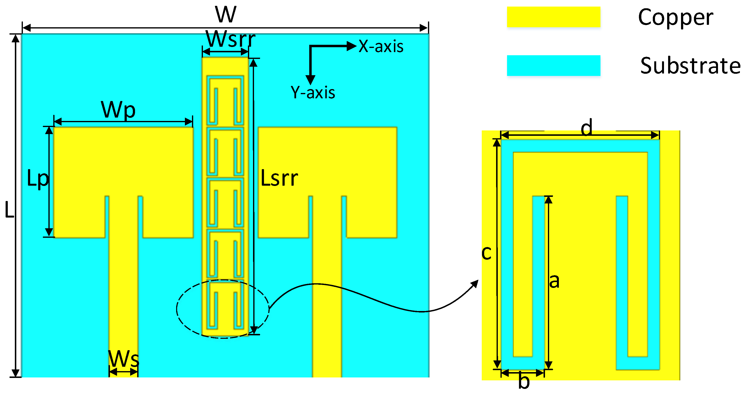
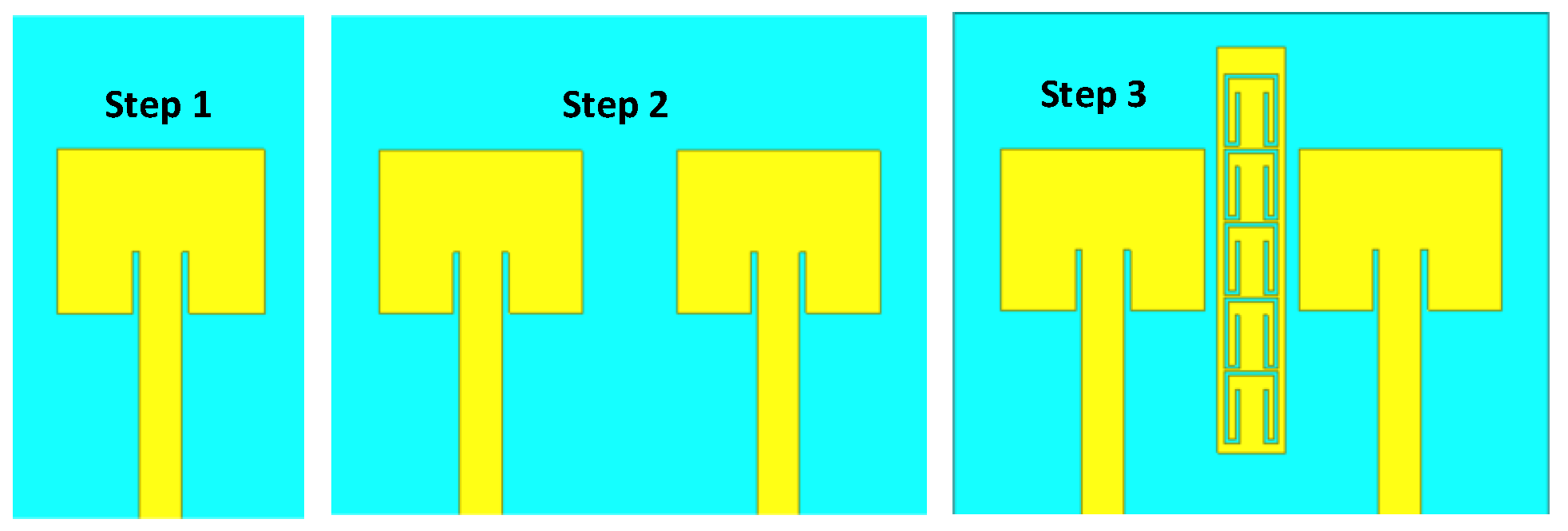
2. Antenna Characterization
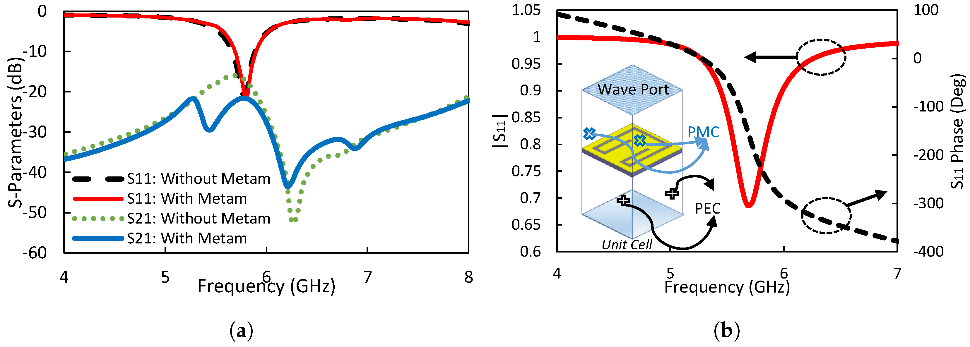
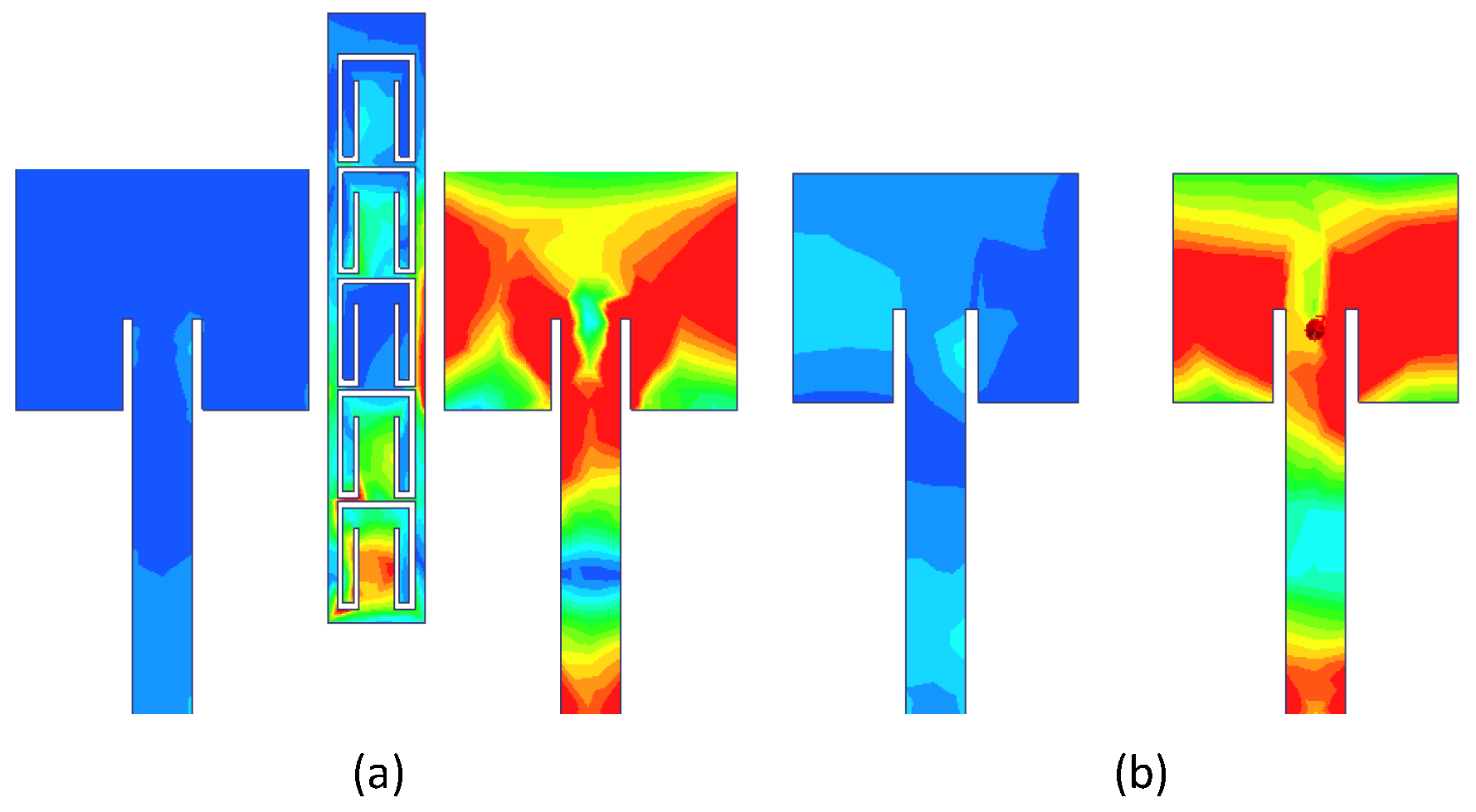
3. Results and Discussions
4. Conclusions
Author Contributions
Funding
Conflicts of Interest
Abbreviations
| DG | Diversity Gain |
| MIMO | Multiple Input Multiple Output |
| dB | Decibel |
| ECC | Envelop Correlation Coefficient |
| CCL | Channel Capacity Loss |
References
- Ludwig, A. Mutual coupling, gain and directivity of an array of two identical antennas. IEEE Trans. Antennas Propag. 1976, 24, 837–841. [Google Scholar] [CrossRef]
- Iqbal, A.; Saraereh, O.A.; Ahmad, A.W.; Bashir, S. Mutual Coupling Reduction Using F-Shaped Stubs in UWB-MIMO Antenna. IEEE Access 2018, 6, 2755–2759. [Google Scholar] [CrossRef]
- Su, S.W.; Lee, C.T.; Chang, F.S. Printed MIMO-antenna system using neutralization-line technique for wireless USB-dongle applications. IEEE Trans. Antennas Propag. 2012, 60, 456–463. [Google Scholar] [CrossRef]
- Ghosh, J.; Ghosal, S.; Mitra, D.; Bhadra Chaudhuri, S.R. Mutual coupling reduction between closely placed microstrip patch antenna using meander line resonator. Prog. Electromagn. Res. 2016, 59, 115–122. [Google Scholar] [CrossRef]
- Zhang, S.; Lau, B.K.; Sunesson, A.; He, S. Closely-packed UWB MIMO/diversity antenna with different patterns and polarizations for USB dongle applications. IEEE Trans. Antennas Propag. 2012, 60, 4372–4380. [Google Scholar] [CrossRef]
- Suntives, A.; Abhari, R. Miniaturization and isolation improvement of a multiple-patch antenna system using electromagnetic bandgap structures. Microw. Opt. Technol. Lett. 2013, 55, 1609–1612. [Google Scholar] [CrossRef]
- Yu, A.; Zhang, X. A novel method to improve the performance of microstrip antenna arrays using a dumbbell EBG structure. IEEE Antennas Wirel. Propag. Lett. 2003, 2, 170–172. [Google Scholar]
- Wu, W.; Yuan, B.; Wu, A. A Quad-Element UWB-MIMO Antenna with Band-Notch and Reduced Mutual Coupling Based on EBG Structures. Int. J. Antennas Propag. 2018, 2018, 8490740. [Google Scholar] [CrossRef]
- Farsi, S.; Aliakbarian, H.; Schreurs, D.; Nauwelaers, B.; Vandenbosch, G.A. Mutual coupling reduction between planar antennas by using a simple microstrip U-section. IEEE Antennas Wirel. Propag. Lett. 2012, 11, 1501–1503. [Google Scholar] [CrossRef]
- Zhu, F.G.; Xu, J.D.; Xu, Q. Reduction of mutual coupling between closely-packed antenna elements using defected ground structure. Electron. Lett. 2009, 45, 601–602. [Google Scholar] [CrossRef]
- Chandel, R.; Gautam, A.K.; Rambabu, K. Design and Packaging of an Eye-Shaped Multiple-Input–Multiple-Output Antenna With High Isolation for Wireless UWB Applications. IEEE Trans. Compon. Packag. Manuf. Technol. 2018, 8, 635–642. [Google Scholar] [CrossRef]
- Zhu, J.; Li, S.; Liao, S.; Xue, Q. Wideband Low-Profile Highly Isolated MIMO Antenna With Artificial Magnetic Conductor. IEEE Antennas Wirel. Propag. Lett. 2018, 17, 458–462. [Google Scholar] [CrossRef]
- Liu, P.; Sun, D.; Wang, P.; Gao, P. Design of a Dual-Band MIMO Antenna with High Isolation for WLAN Applications. Prog. Electromag. Res. 2018, 74, 23–30. [Google Scholar] [CrossRef]
- Sharawi, M.S. Printed MIMO Antenna Engineering; Artech House: Norwood, MA, USA, 2014. [Google Scholar]
- Choukiker, Y.K.; Sharma, S.K.; Behera, S.K. Hybrid fractal shape planar monopole antenna covering multiband wireless communications with MIMO implementation for handheld mobile devices. IEEE Trans. Antennas Propag. 2014, 62, 1483–1488. [Google Scholar] [CrossRef]


| Parameters | Dimension (mm) | Parameters | Dimension (mm) | Parameters | Dimension (mm) |
|---|---|---|---|---|---|
| L | 37 | W | 44 | Ws | 3 |
| a | 4 | b | 1.1 | Lssr | 30 |
| Wp | 15 | c | 5.3 | d | 4 |
| Lp | 13 | Wssr | 5 | - | - |
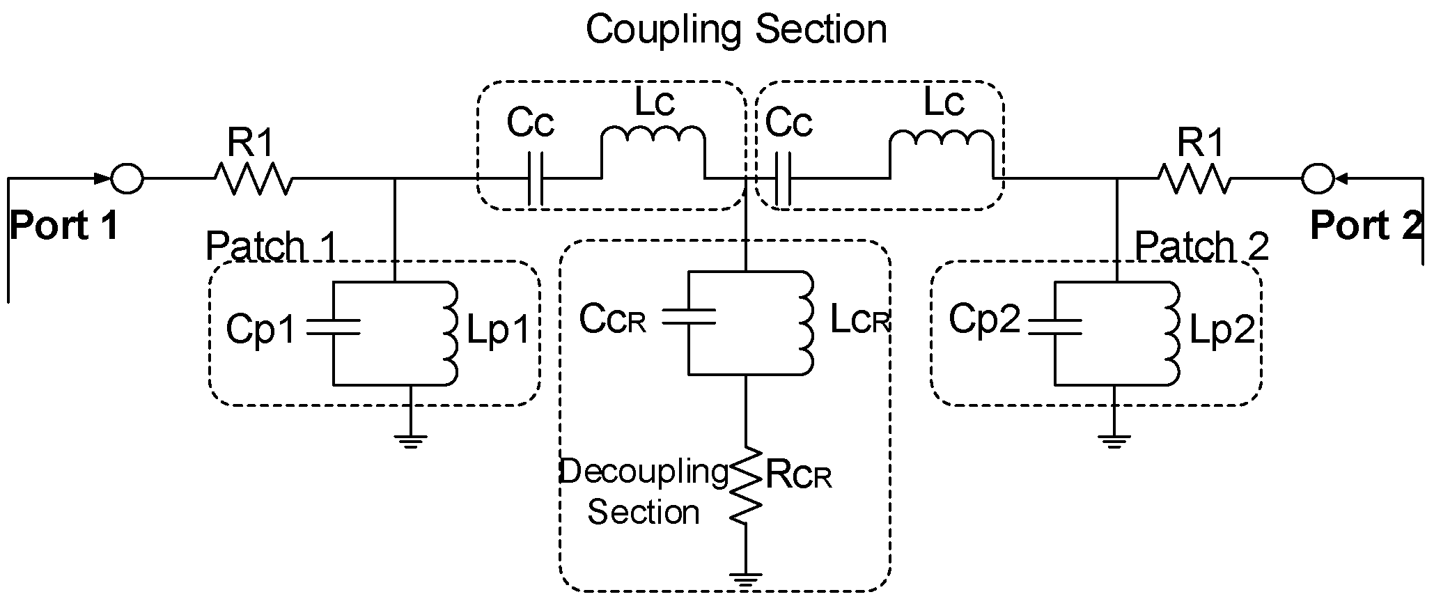
| R1 () | Cc (pF) | Lc (nH) | Lp1/Lp2 (nH) | Cp1/Cp2 (pF) | CcR (pF) | LcR (nH) | RcR () |
|---|---|---|---|---|---|---|---|
| 466.75 | 1.2 | 2.15 | 0.83 | 1.31 | 0.01 | 0.64 | 0.01 |
© 2018 by the authors. Licensee MDPI, Basel, Switzerland. This article is an open access article distributed under the terms and conditions of the Creative Commons Attribution (CC BY) license (http://creativecommons.org/licenses/by/4.0/).
Share and Cite
Iqbal, A.; A Saraereh, O.; Bouazizi, A.; Basir, A. Metamaterial-Based Highly Isolated MIMO Antenna for Portable Wireless Applications. Electronics 2018, 7, 267. https://doi.org/10.3390/electronics7100267
Iqbal A, A Saraereh O, Bouazizi A, Basir A. Metamaterial-Based Highly Isolated MIMO Antenna for Portable Wireless Applications. Electronics. 2018; 7(10):267. https://doi.org/10.3390/electronics7100267
Chicago/Turabian StyleIqbal, Amjad, Omar A Saraereh, Amal Bouazizi, and Abdul Basir. 2018. "Metamaterial-Based Highly Isolated MIMO Antenna for Portable Wireless Applications" Electronics 7, no. 10: 267. https://doi.org/10.3390/electronics7100267