1. Introduction
Permanent magnet synchronous motors (PMSM) have a lot of merits such as high reliability, high efficiency, simple construction, and good control performance, and thus, it has been applied in various control systems including electrical drives, industrial applications, and medical devices in recent years [
1,
2,
3,
4,
5,
6,
7]. Direct torque control (DTC) and field-oriented control (FOC) are two widely applied high-performance control strategies for the PMSM. Different from the decoupled-analyzing method in FOC, torque and flux linkage are controlled directly in DTC, and therefore, the quickest dynamic response can be obtained in the PMSM driven by DTC. However, as only six active vectors can be selected to compensate the errors of flux linkage and torque in conventional DTC (CDTC), the PMSM suffers from some drawbacks, such as large torque and flux linkage ripples. To improve the steady-state performance of the PMSM, many researchers have attempted to reduce these ripples by adding the amount of the active vectors through different methods.
With more appropriate active vectors selected in each control period, a novel DTC-fed PMSM system is proposed on the basis of a three-level inverter [
8,
9], and thus, the ripples of torque and flux linkage in PMSM can be suppressed effectively. In References [
10,
11], a novel DTC strategy using a matrix converter is proposed. Four enhanced switching tables are designed for the selection of switching states, and therefore, the ripples of the PMSM can be reduced effectively. Despite the fact that multiple active vectors can be supplied by three-level inverter or matrix converter, the cost of the DTC system is inevitably increased.
In fact, torque error and flux linkage error are tiny in most cases, and therefore, these errors will be over-compensated if the selected vector is applied over the whole control period. To solve these problems, duty ratio modulation strategy is introduced into the DTC-fed PMSM. Different duty ratio modulation methods for DTC (DDTC) are studied in References [
12,
13,
14,
15,
16], and the ripples of torque and flux linkage can be reduced effectively without degrading the fast dynamic response in CDTC. In Reference [
17], a new suboptimal control algorithm applying dynamic programming and a ramp trajectory method is proposed to DB-DTFC. In DB-DTFC, the maximum torque changes in one inverter switching period are used to determine the number of quantized stages for the minimum-time ramp trajectory method. It can be found that, the error compensational effects are considered in DB-DTFC, and therefore, torque and flux linkage command trajectories can be developed in different shapes according to the desired objectives, and fast dynamic responses can be achieved easily.
The stator flux linkage currents are decoupled in
d-
q axes and controlled independently in FOC, and thus, the outstanding operating performance of the PMSM can be obtained easily. The decoupled-analysis method is adopted in the novel DTC based on a space vector modulation (SVM) strategy with simple proportional-integral (PI) regulator or sliding mode observer [
18,
19,
20,
21,
22,
23,
24,
25]. With the independent control of torque and flux linkage in SVM-DTC, the amplitude and the phase of the wanted active vector can be determined accurately, and the errors of torque and flux linkage can be compensated precisely. However, the introduced PI regulator or sliding mode observer will degrade the dynamic response of the system.
To improve the operation performance of PMSM effectively, a novel DTC scheme utilizing composite active vectors modulation (CVM) strategy is presented in this paper. The compensational effects of torque error and flux linkage error in the PMSM driven by different control strategies are analyzed. Subsequently, the precondition of the accurate error compensation is obtained, and then, the precondition is adopted to determine the applied control strategy for the PMSM in different operation conditions, which is ignored in SVM-DTC and CDTC.
It should be noted that the most complicated control process is the transient-state. The large error component should be compensated fully, and the low error component should not be over-compensated; therefore, the duty ratio direct torque control strategy which, considering the active angles and the impact angles in Reference [
1], can be used. The effectiveness of the proposed CVM-DTC scheme is validated through the experimental results. It should be noted that the steady-state performance and the dynamic response of the PMSM driven by CDTC, DDTC, and SVM-DTC are also studied in this paper.
The rest of this paper comprises the following sections. The principles of the conventional DTC are analyzed in
Section 2. The compensational effects of torque error and flux linkage error in the SVM-DTC system are also illustrated in
Section 2. The dividing process of the PMSM operation conditions and the error compensational effect supplied by different vectors in different operation conditions are described in
Section 3 and the precondition of the accurate error compensations are also analyzed in
Section 3. The description of experimental setup and discussions on experimental results are given in
Section 4. The conclusion is analyzed in
Section 5.
3. Analysis of Error Compensations
The ripples of torque and flux linkage in the PMSM driven by SVM-DTC are relatively minor while the PMSM is operated in the steady-state condition. On the other hand, the dynamic performance will be affected by the complicated calculations of the synthesis voltage vector and the over-modulation process while the PMSM is operated in the dynamic response condition. This is the main reason that the fast dynamic performance of permanent magnet synchronous motor driven by SVM-DTC is degraded.
To improve the steady-state performance of PMSM, and maintain the fast dynamic response at the same time, appropriate control strategy should be selected and applied to the system according to the operation conditions, including CDTC, DDTC, and SVM-DTC. Therefore, the differences of the error compensational effects provided by the synthesis voltage vector and single active vector under different operation conditions should be analyzed firstly.
3.1. Operation Conditions
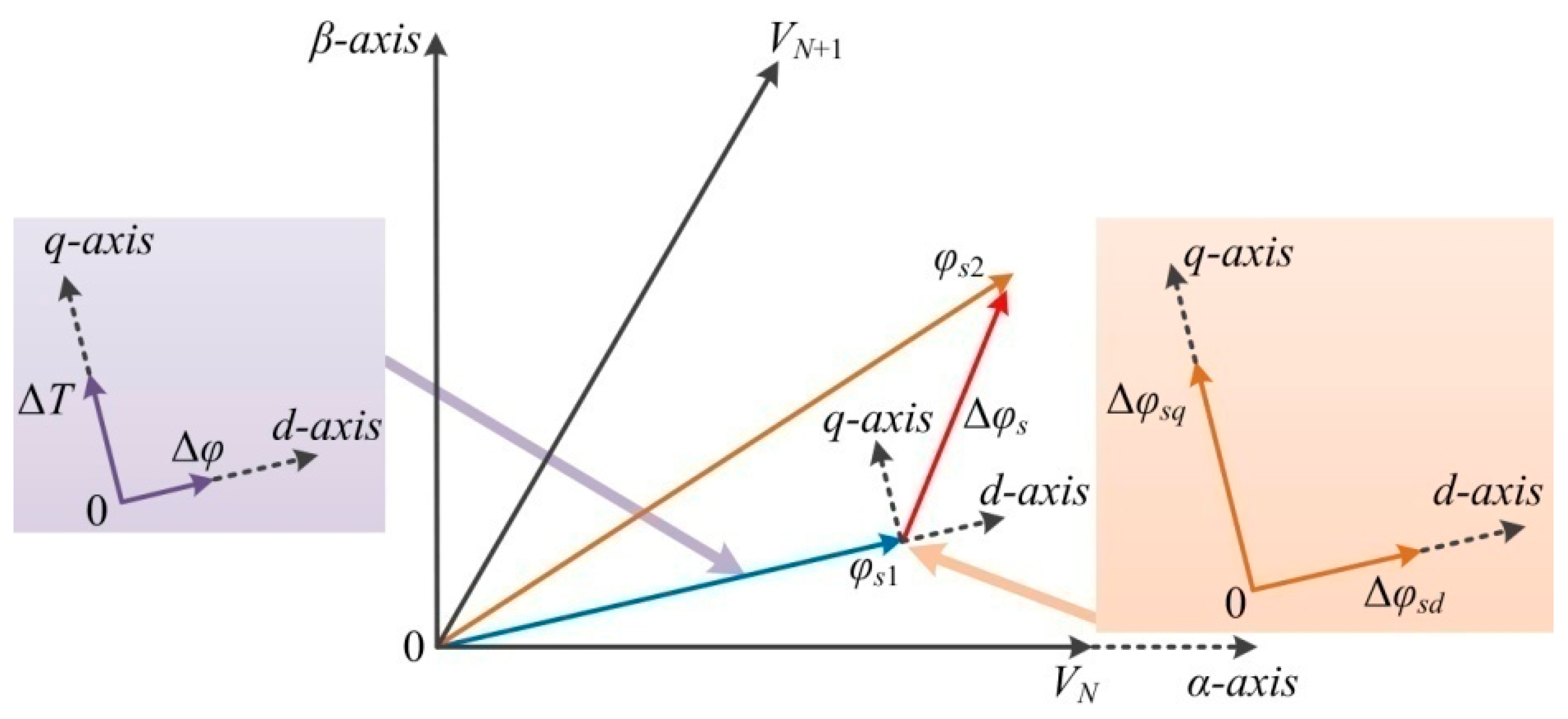
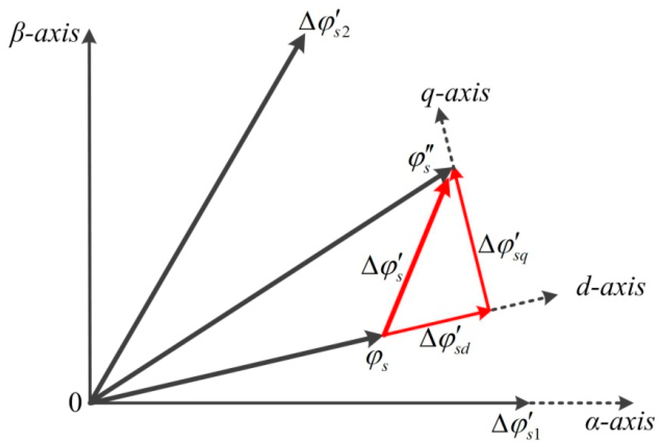
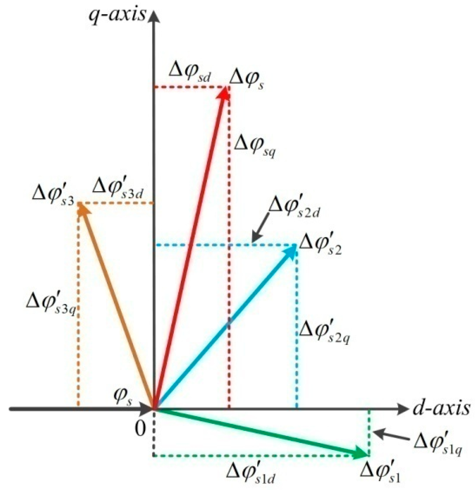
The stator flux linkage
φs changes from
φs1 to
φs2 during one control period and the variation of the stator flux linkage
φs is Δ
φs, which can be decoupled into Δ
φsd and Δ
φsq in the
d-q axis. In this control period, the errors of torque and flux linkage are Δ
T and Δ
φ, respectively. Hence, the torque component variation of the stator flux linkage is Δ
φsq, and the amplitude component variation of the stator flux linkage is Δ
φsd, as shown in
Figure 4.
The torque component variation and the amplitude component variation of the stator flux linkage can be expressed as
where
Ls is the stator inductance,
p is the number of pole pairs, and
φf is the permanent magnet flux linkage.
The compensational effect of the stator flux linkage supplied by single active vector
VN and synthesis voltage vector
us are
and
, respectively, as shown in
Figure 5.
The torque component compensation of the stator flux linkage supplied by synthesis voltage vector us is , and the amplitude component compensation of the stator flux linkage provided by synthesis voltage vector us is . It is obvious that the parameters of , , and are fixed during each control period in the system. While the torque error ΔT and the flux linkage error Δφ will vary with the variation of the stator flux linkage location in different control period. Therefore, the real values of Δφsq and Δφsd are also different.
The relationships between the real error compensations of the stator flux linkage and the errors can be described in the following way.
First item, the actual compensations are greater than the errors:
Second item, the actual compensations are less than the errors:
Third item, the actual compensation of the amplitude component is less than the error while the actual compensation of torque component is greater than the error:
Fourth item, the actual compensation of the amplitude component is greater than the error while the actual compensation of torque component is less than the error:
The operation conditions of the PMSM can be divided into three items in accordance with the errors and the actual compensations, as shown in
Table 2.
3.2. Error Compensation Analysis in Steady-State Case
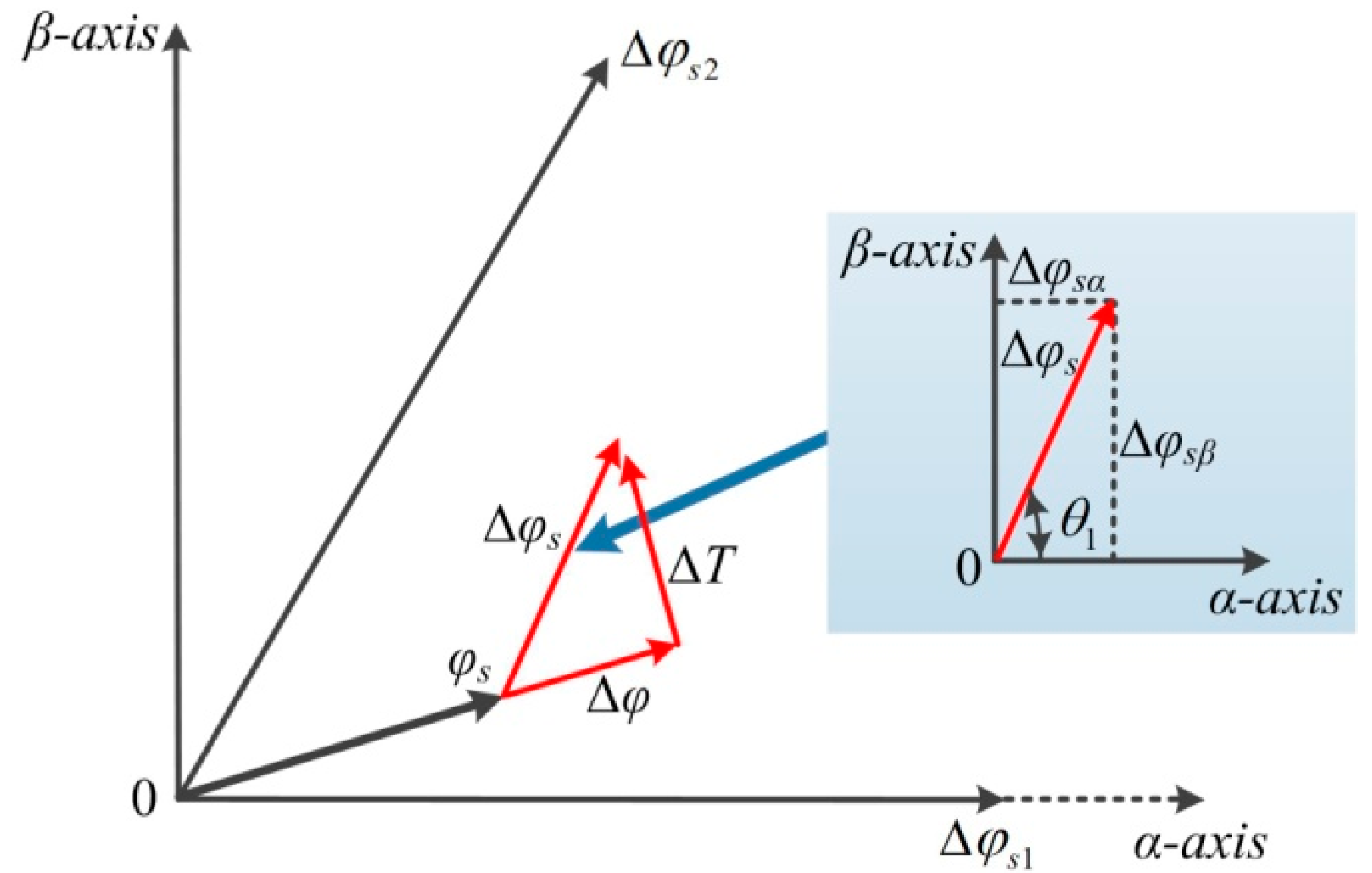
The values of torque error Δ
T and flux linkage error Δ
φs are relatively low in steady-state case [
6]. The angle between the stator flux linkage
φs and the active vector
VN is
θ1, as shown in
Figure 6. It is also shown in
Figure 6 that both the compensations of Δ
T and Δ
φs are bigger than the errors. Consequently, the errors will be over-compensated if the active vector or the synthesized voltage vector is applied during the entire control period.
In DDTC-fed PMSM, the applied time of the active vector is modulated by duty ratio modulation strategy. As a result, the over-compensation of the errors can be avoided; nevertheless, the fixed active vectors limit the compensational effects.
In the PMSM driven by SVM-DTC, the adjacent active vectors
VN and
VN+1 are selected as the benchmark vectors to obtain the synthesized voltage vector
us. Furthermore, the applied time of
VN and
VN+1 are
T1 and
T2, respectively. The error compensations can be evaluated by
The modulation process of the active vectors can be expressed as
where
T0 is the zero voltage vector applied time.
From the aforementioned analyses, it can be found that the errors of torque and flux linkage can be compensated accurately through SVM strategy while the PMSM is operated in steady-state.
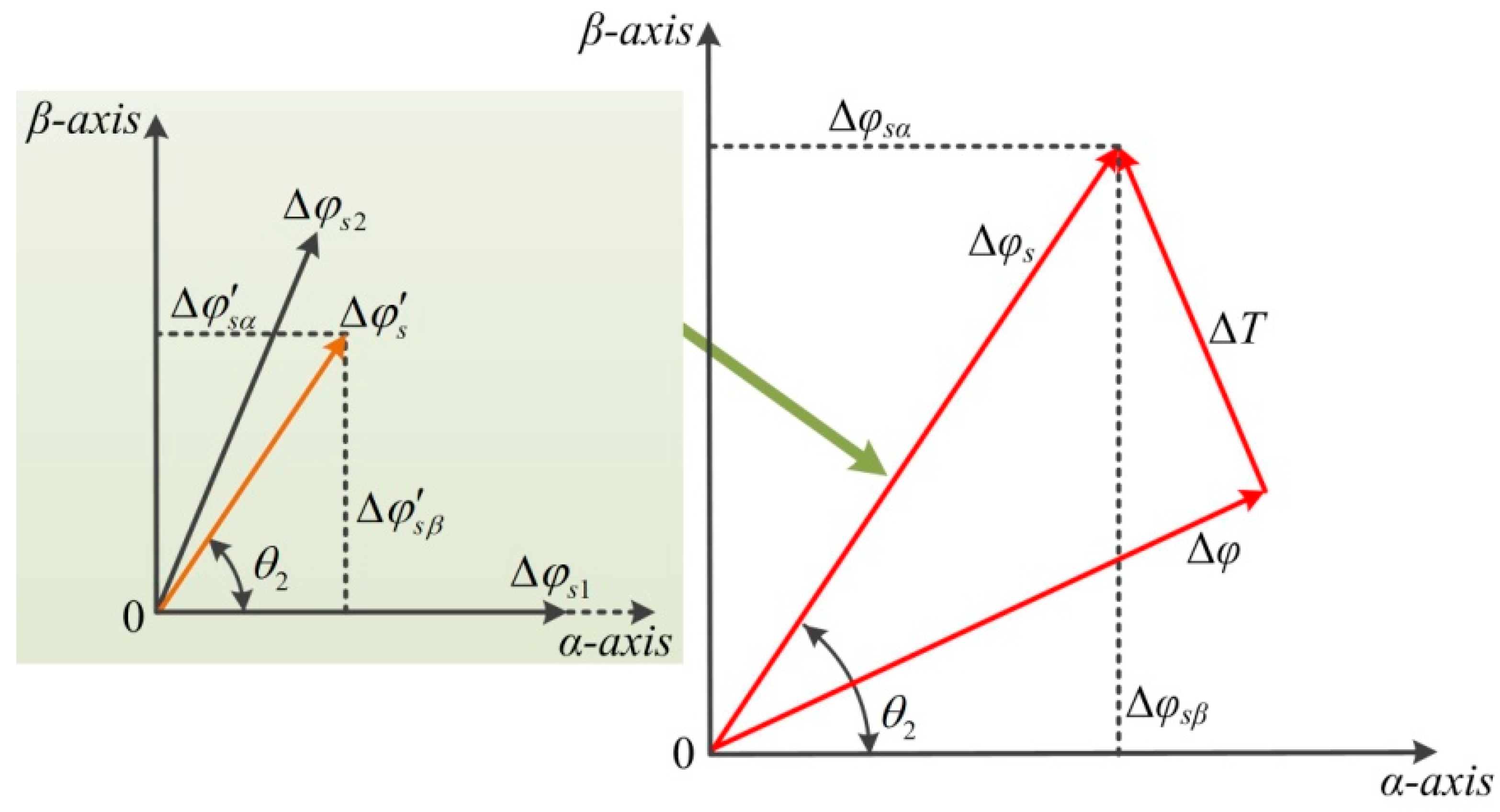
3.3. Error Compensation Analysis in Dynamic-State Case
The errors of torque or flux linkage may become greater in the dynamic-state while the speed or the torque changes. As shown in
Figure 7, the stator flux linkage error is Δ
φs; the angle between the stator flux linkage error Δ
φs and the active vector
VN is
θ2. It can be found that the torque error and the flux linkage error are greater than the error compensations.
It can be found that the torque error ΔT and the flux linkage error Δφ cannot be compensated fully by any single active vector or the synthesized voltage vector in the next control period. The differences of the error compensation effect supplied by the single active vector or the synthesized voltage vector are described in following parts.
3.3.1. Synthetic Voltage Vector
The adjacent active vectors
VN and
VN+1 are selected as the benchmark vectors. The applied time of
VN and
VN+1 are
T1 and
T2, respectively. Therefore, the error compensations can be calculated as
Since the actual compensations are smaller than the errors, therefore
The applied time of the applied active vectors can be over-modulated as
The applied time of the applied active vectors can be rewritten as
where
k1 and
k2 are the duty ratio values of applied time of
VN and
VN+1, respectively.
Therefore, the actual compensation of the stator flux linkage in one control period is
which can be simplified as
Therefore, the compensation of the stator flux linkage supplied by synthesized voltage vector
us can be given as
3.3.2. Single Active Vector
The compensations of the stator flux linkage supplied by adjacent vectors
VN and
VN+1 during the whole control period are
Therefore, the compensations of the stator flux linkage provided by the single active vector can be expressed as
The comparison result of the stator flux linkage compensations supplied by the different vectors can be described as
From the aforementioned analyses, it can be observed that the compensational effects of the stator flux linkage supplied by the synthesized voltage vector is weaker than the single active vector. Therefore, the SVM strategy is not required to compensate the errors of torque and flux linkage while the PMSM is operated in the dynamic state. To simplify the calculations of the system, the appropriate active vector can be selected from a conventional switching table and be used in the system over the entire control period.
In short, CDTC strategy should be used to reduce the ripples of torque and flux linkage in the PMSM when the PMSM is operated in a dynamic state. Hence, the delayed dynamic response caused by the PI controller can be eliminated, and the ripples’ depressing effects of the PMSM driven by CDTC are the same as that driven by SVM-DTC.
3.4. Error Compensation Analysis in Transient-State Case
The operation condition of the PMSM may deviate the steady-state due to external disturbance. Therefore, the PMSM may operate in a transient-state if one parameter of torque error and flux linkage error is large while another parameter is relatively low.
The torque error Δ
T is high and the flux linkage error Δ
φ is relatively low as shown in
Figure 8. The variation of the stator flux linkage is Δ
φs.
The differences of the error compensation effect supplied by single active vector or synthesized voltage vector are described in the following section.
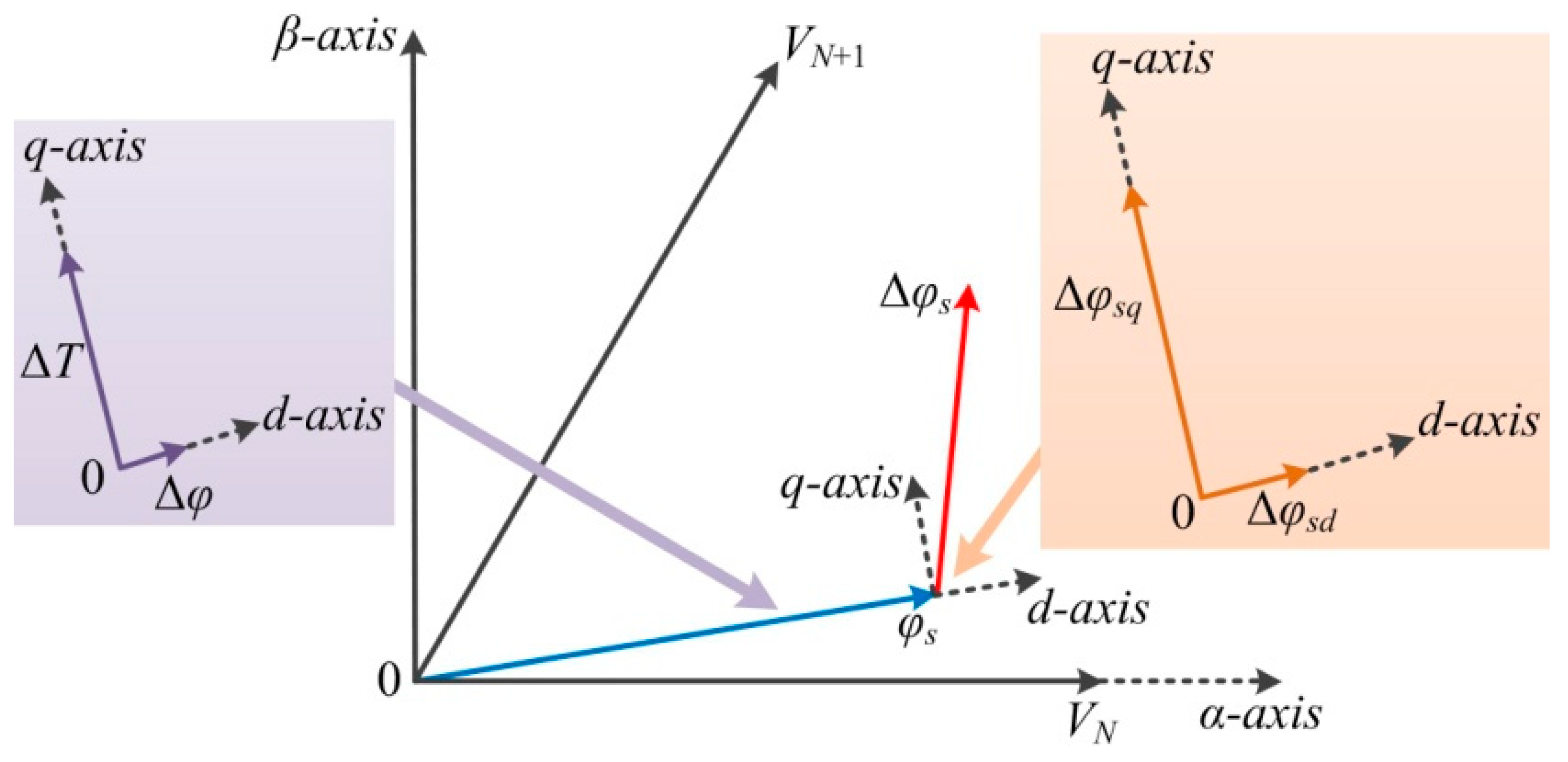
3.4.1. Synthetic Voltage Vector
Figure 9 shows the error compensational effects provided by different active vectors.
As shown in
Figure 9, the adjacent active vectors
VN+1 and
VN+2 are selected as the benchmark vectors. The applied time of
VN+1 and
VN+2 are
T1 and
T2, respectively. Therefore, the error compensations can be evaluated by
3.4.2. Single Active Vector Vn
The stator flux linkage error Δ
φs is located in the middle of error compensations
and
, as shown in
Figure 9. To compensate the error Δ
φsq effectively and avoid the over-compensation of the error Δ
φsd at the same time, the adjacent vectors
VN+1 and
VN+2 can be selected and applied to half of the control period.
From the above analysis, it can be found that the torque error can be compensated fully supplied by a single active vector while the PMSM is operated in the transient-state; however, the flux linkage error cannot be compensated fully. Despite the fact that the torque error and the flux linkage error can be compensated fully by synthetic voltage vector, the calculations of the system are inevitably increased. It should be noted that the novel DDTC strategy based on the active angle in Reference [
1] has solved the problem while one parameter is large and another parameter is relatively small. Therefore, the DDTC strategy can be used to improve the performance of the system while the PMSM is operated in a transient-state.
3.5. Novel Composite Active Vectors Modulation Strategy
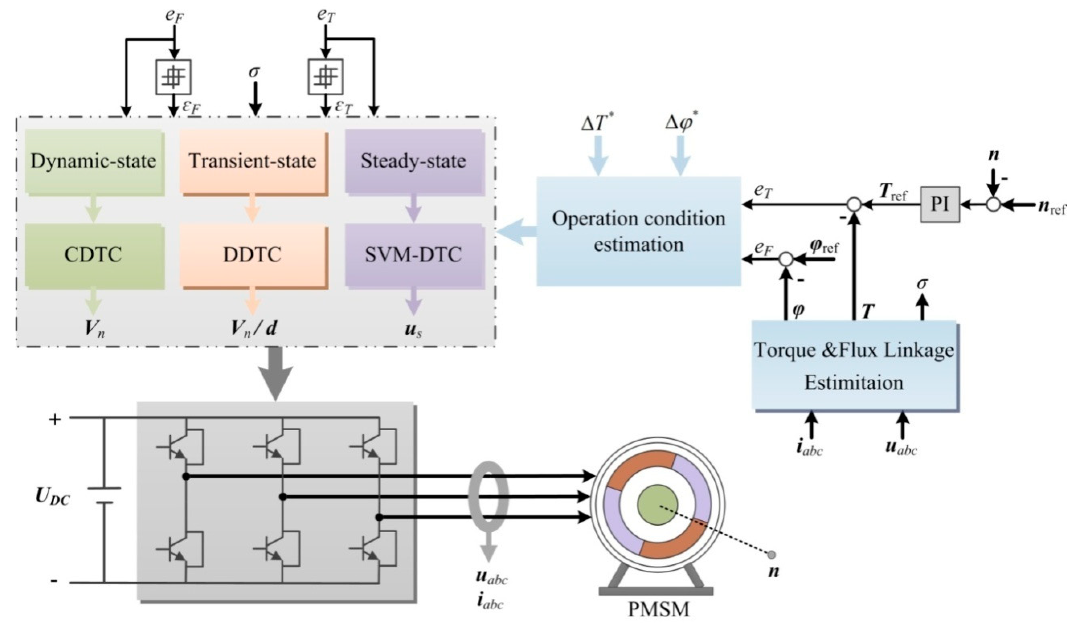
To improve the operation performance of the PMSM effectively, a novel composite active vectors modulation DTC (CVM-DTC) strategy considering the precondition of the accurate errors compensations is presented in this section. The schematic diagram of the presented CVM-DTC system is shown in
Figure 10. The parameters in CVM-DTC are defined by:
uabc: Stator voltage;
iabc: Stator currents;
UDC: DC bus voltage;
n: Actual rotor speed;
nref: Reference rotor speed;
σ: Rotor position;
Tref: Reference torque;
φref: Reference flux linkage;
ΔT: *Reference torque compensation;
Δφ: *Reference flux linkage compensation;
Vn: Single active vector;
d: Duty ratio value of applied time;
us: Synthetic voltage vector.
In order to maintain the fast dynamic response in CDTC and obtain the minimum ripples of the system, the applied control strategy should adjust according to the operation conditions of the PMSM.
The precondition of the accurate compensations of torque error and flux linkage error is that the torque error and the flux linkage error can be compensated and fully supplied by the applied active vector in the whole control period. However, this precondition is ignored in the SVM-DTC system. Therefore, the torque error and the flux linkage error will be analyzed through decoupled calculations through PI controllers, while the compensational effects of the stator flux linkage in SVM-DTC and CDTC when the PMSM is operated in non-steady-state are nearly the same. As a result, the error compensational effects are not satisfied and the dynamic response will be affected without considering the operation conditions of the PMSM.
3.6. Determining of the Operation Condition through Effect Factors
The relationship between the active vector
Vn and the stator flux linkage variation Δ
φs in each control period is
During the whole control period, the max compensations of Δ
φsq and Δ
φsd can be expressed as
The max compensation of the torque is
And the max compensation of the flux linkage is
Defining the reference values of torque variation and flux linkage variation are Δ
T* and Δ
φ*, respectively, which can be expressed as
The effect factors of torque and flux linkage are
kT and
kφ, respectively, which can be given as
The introduced effect factors can be obtained through the errors and the reference values of the variation in any control period. The operation conditions of the PMSM can be classified into three cases: steady-state, transient-state, and dynamic-state. The relationships between the effect factors and the operation conditions are shown in
Table 3.
4. Experimental Analysis
4.1. Experimental System Setup
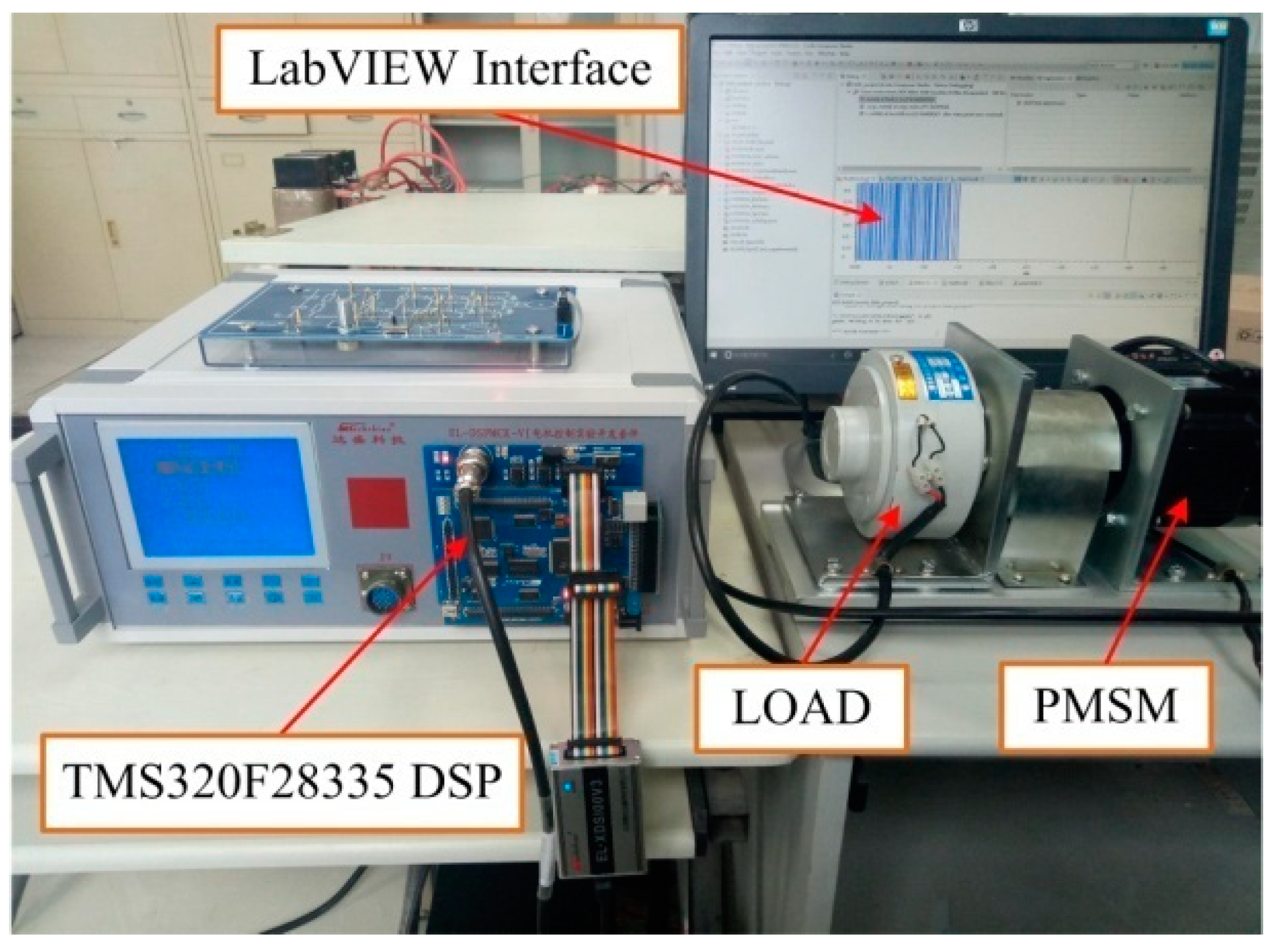
Experimental studies are carried out on a 100-W PMSM drive system to validate the feasibility and effectiveness of the proposed CVM-DTC strategy. The experimental hardware setup is illustrated in
Figure 11. The parameters of the PMSM are given as follows:
Rs = 0.76 Ω;
Ls = 0.00182 H; the number of pole pairs
p = 4. The DC voltage is 36 V. This study compares the steady-state and the dynamic response performance of CDTC, DDTC, SVM-DTC, and CVM-DTC. The experiments are implemented in a TMS320F28335 DSP control system with a sampling period of 100 μs.
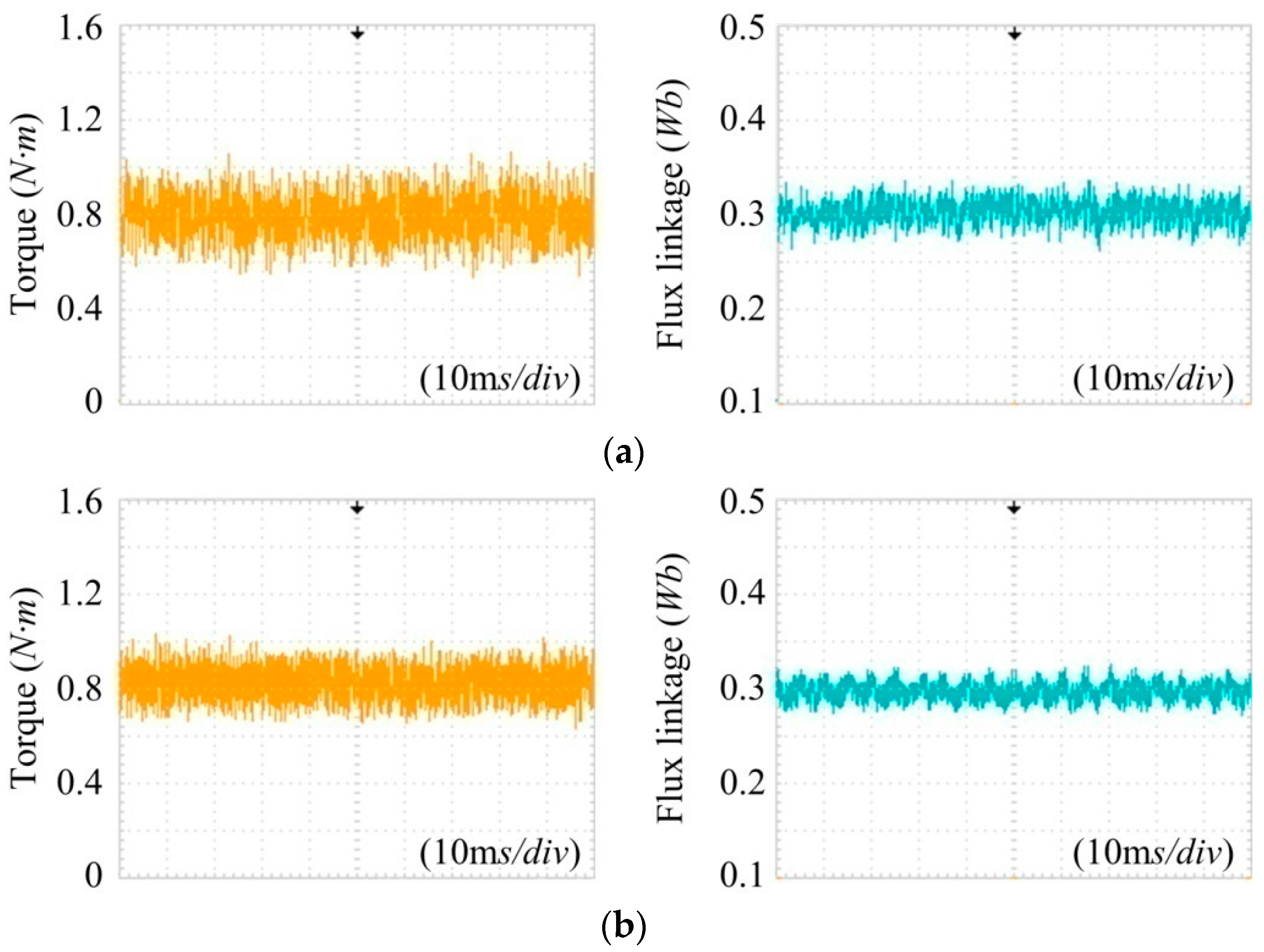
4.2. Steady-State Performance
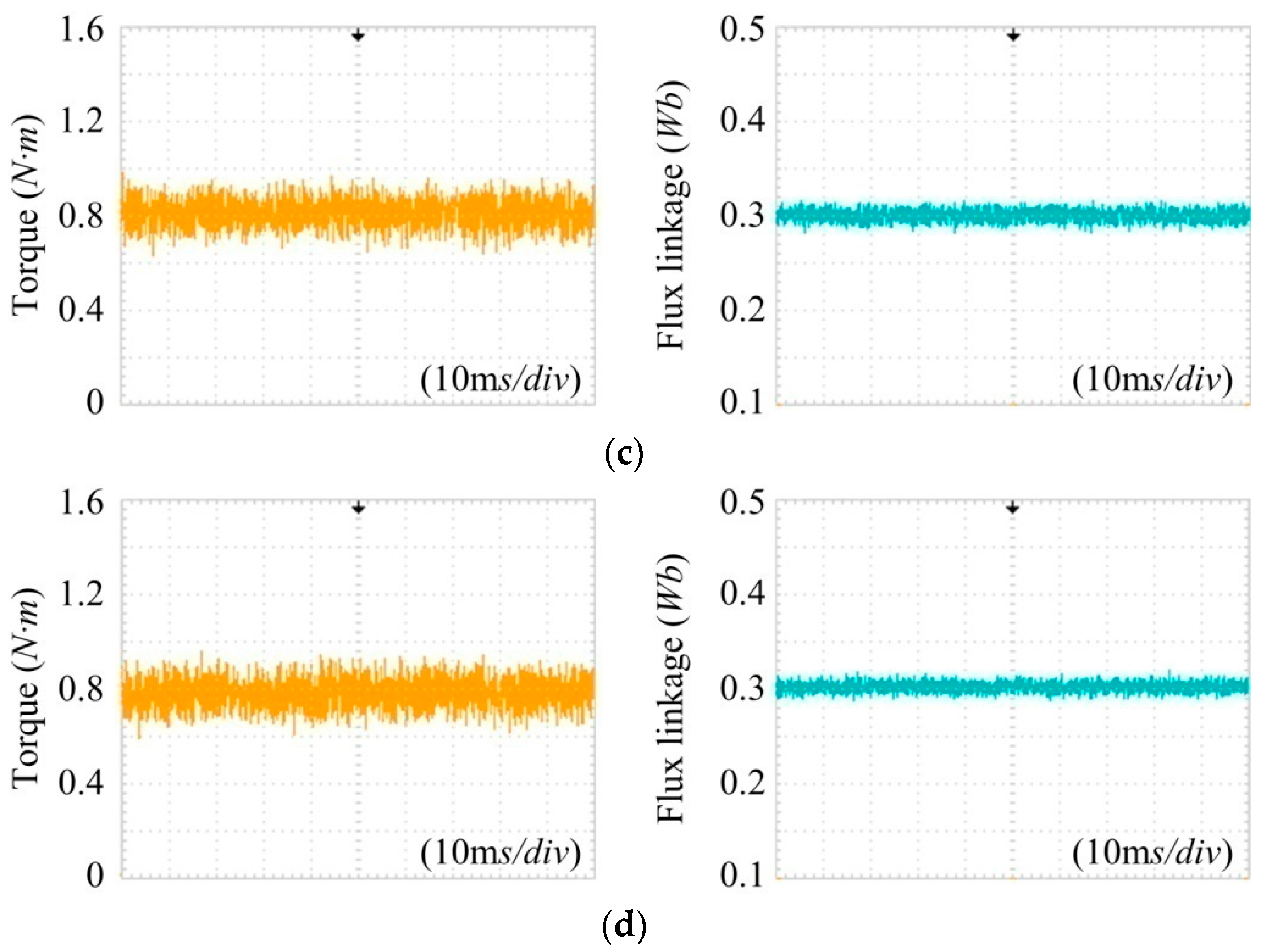
The steady-state performances of CDTC, DDTC, SVM-DTC, and CVM-DTC are compared under the same operating conditions. The PMSM is operated at 500 rpm and the reference values of torque and flux linkage are 0.8 N·m and 0.3 Wb, respectively. The torque and flux linkage waveforms of the PMSM are driven by different control strategies as shown in
Figure 12.
From these experimental results, it can be found that the torque ripples of CDTC, SV-DDTC, SVM-DTC, and CVM-DTC are 0.56, 0.4, 0.32, and 0.34 N·m, respectively, and the flux linkage ripples of the four control system are 0.08, 0.06, 0.04, and 0.038 Wb, respectively. Therefore, compared with CDTC, DDTC and SVM-DTC can reduce the torque ripple by at least 28% and 42%, respectively, and reduce the flux linkage ripple at least 25% and 50%, respectively. While the steady-state performances of the PMSM driven by CVM-DTC in the setting operation conditions are nearly the same as SVM-DTC. The experimental results show that the errors of torque and flux should be compensated through SVM-DTC strategy, which indicates that the applied control strategy in CVM-DTC in the steady-state condition is appropriate.
4.3. Dynamic Performance
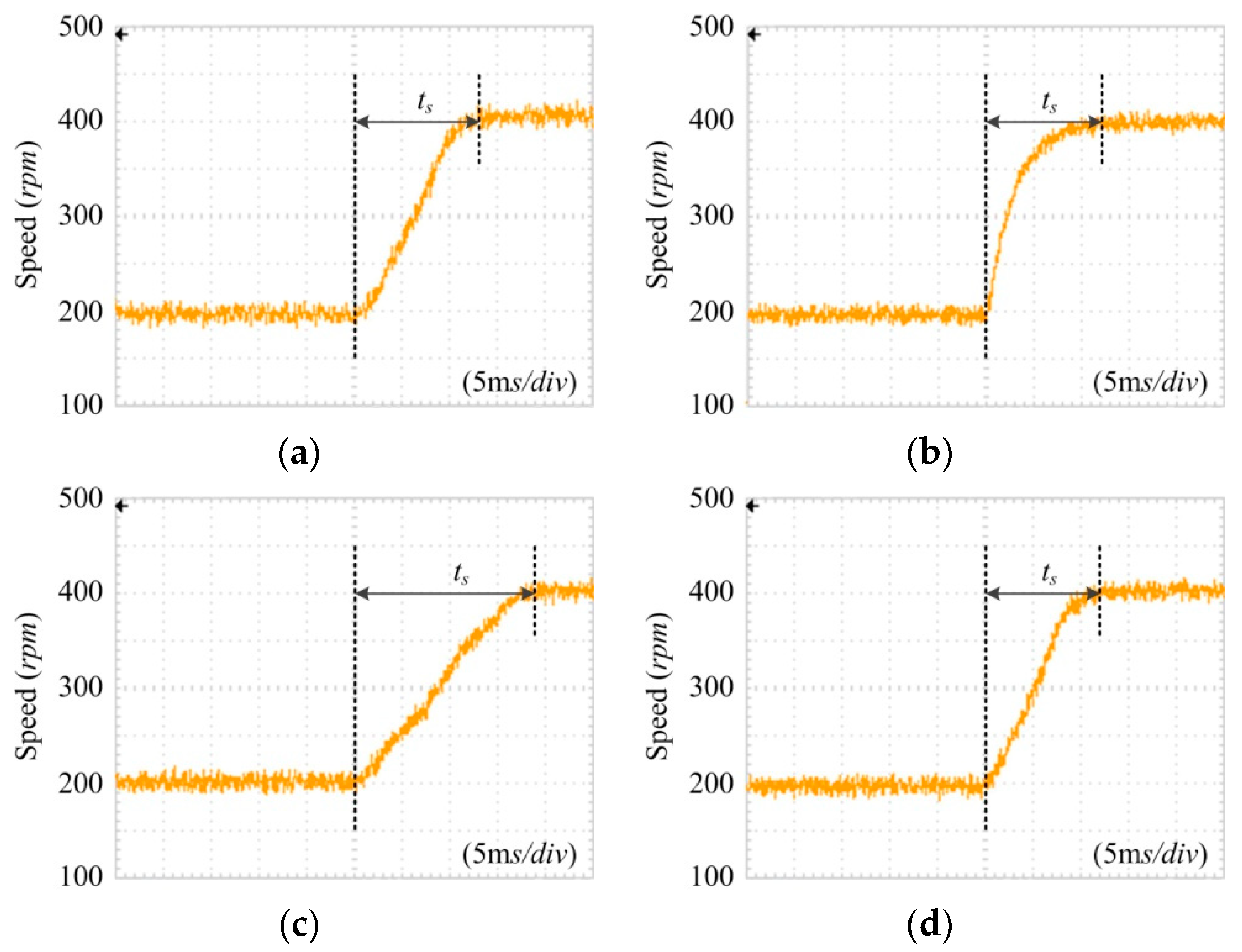
To validate the fast dynamic response of the proposed novel CVM-DTC, the speed responses of the PMSM driven by the four control strategies are tested when the torque is set as 0.5 N·m. In these tests, a step change from 200 to 400 rpm is applied on the speed reference, as shown in
Figure 13.
It can be seen that the ripple of the rotor speed is 35 rpm when using CDTC, while the speed ripples of the PMSM can be reduced to 30, 25, and 24 rpm with the use of DDTC, SVM-DTC, and CVM-DTC. Moreover, the settling times of the rotor speed using the four different control strategies are 0.013, 0.012, 0.019, and 0.012 s.
Therefore, the main advantage of CDTC, i.e., the fast dynamic response, is maintained in CVM-DTC. The experimental results show that dynamic response has a higher priority than ripples in dynamic-state condition, hence, DDTC or SVM-DTC should be abandoned. In short, the applied control strategy in CVM-DTC in the dynamic-state condition is appropriate.
5. Conclusions
The precondition of the accurate compensations of torque error and flux linkage error is considered in the proposed novel CVM-DTC scheme in this paper, which is ignored in CDTC and SVM-DTC. Therefore, the compensational effects of torque error and flux linkage error provided by the single active vector or synthetic voltage vector in different operation conditions are analyzed firstly, and then, the operating conditions of the PMSM are divided into three cases according to the compensational effects (effect factors). To improve the performance of the PMSM effectively, the applied control strategy for the PMSM in different sampling periods will vary on the basis of the introduced effect factors.
Experimental results clearly indicate that the novel CVM-DTC scheme exhibits excellent control of torque and flux linkage with lower steady-state ripples when compared to CDTC and DDTC, and faster transient response performances when compared to SVM-DTC.


