
Research on the Car Searching System in the Multi-Storey Garage with the RSSI Indoor Locating Based on Neural Network

Abstract
:1. Introduction
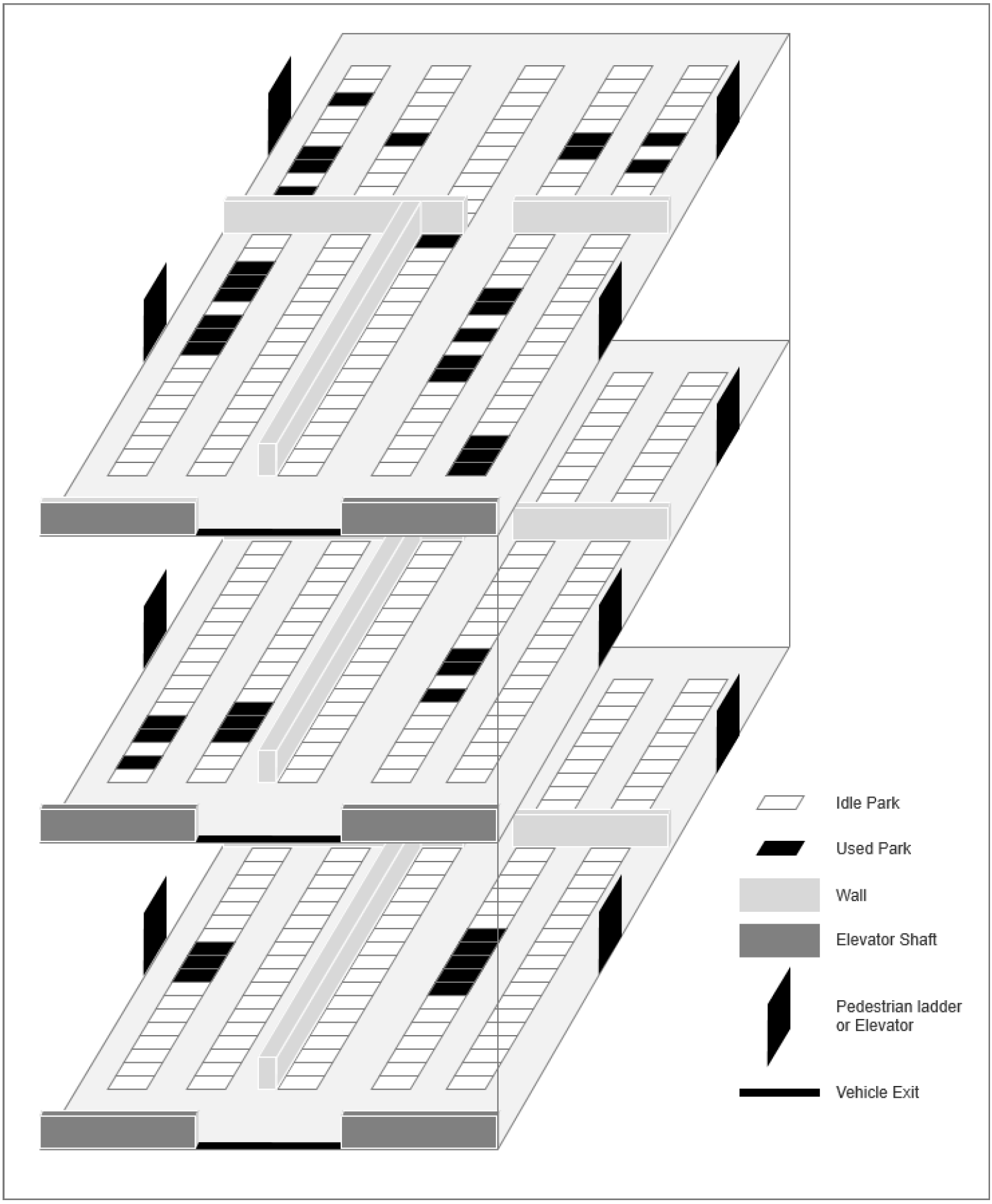
2. Scheme Design
3. Method Research
3.1. Parking Vehicle Detection and Identification Module
3.1.1. YOLOv5 Network
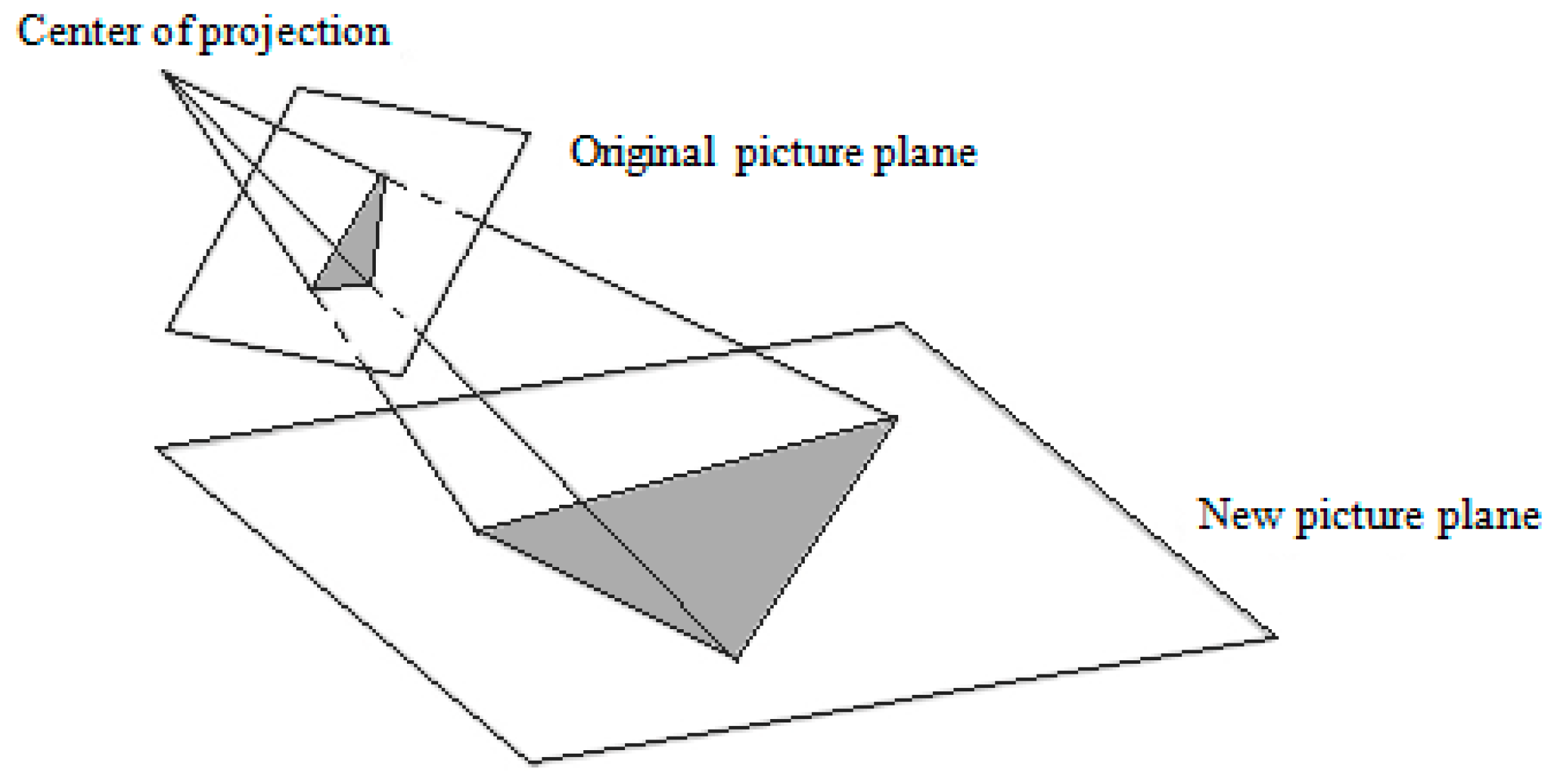
3.1.2. License Plate Correction Module Design
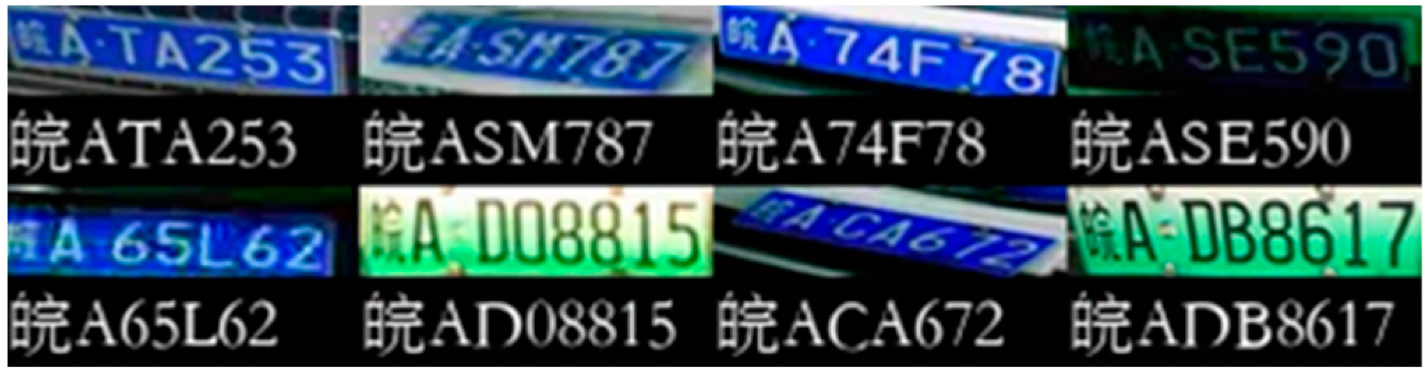
3.1.3. Design of License Plate Recognition Module
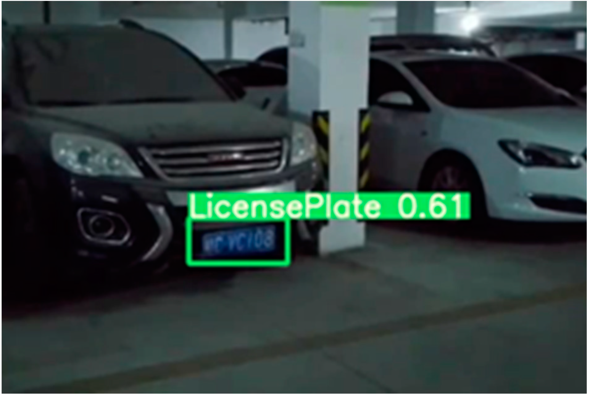
3.1.4. Model Results and Analysis
3.2. Indoor Positioning Service Module
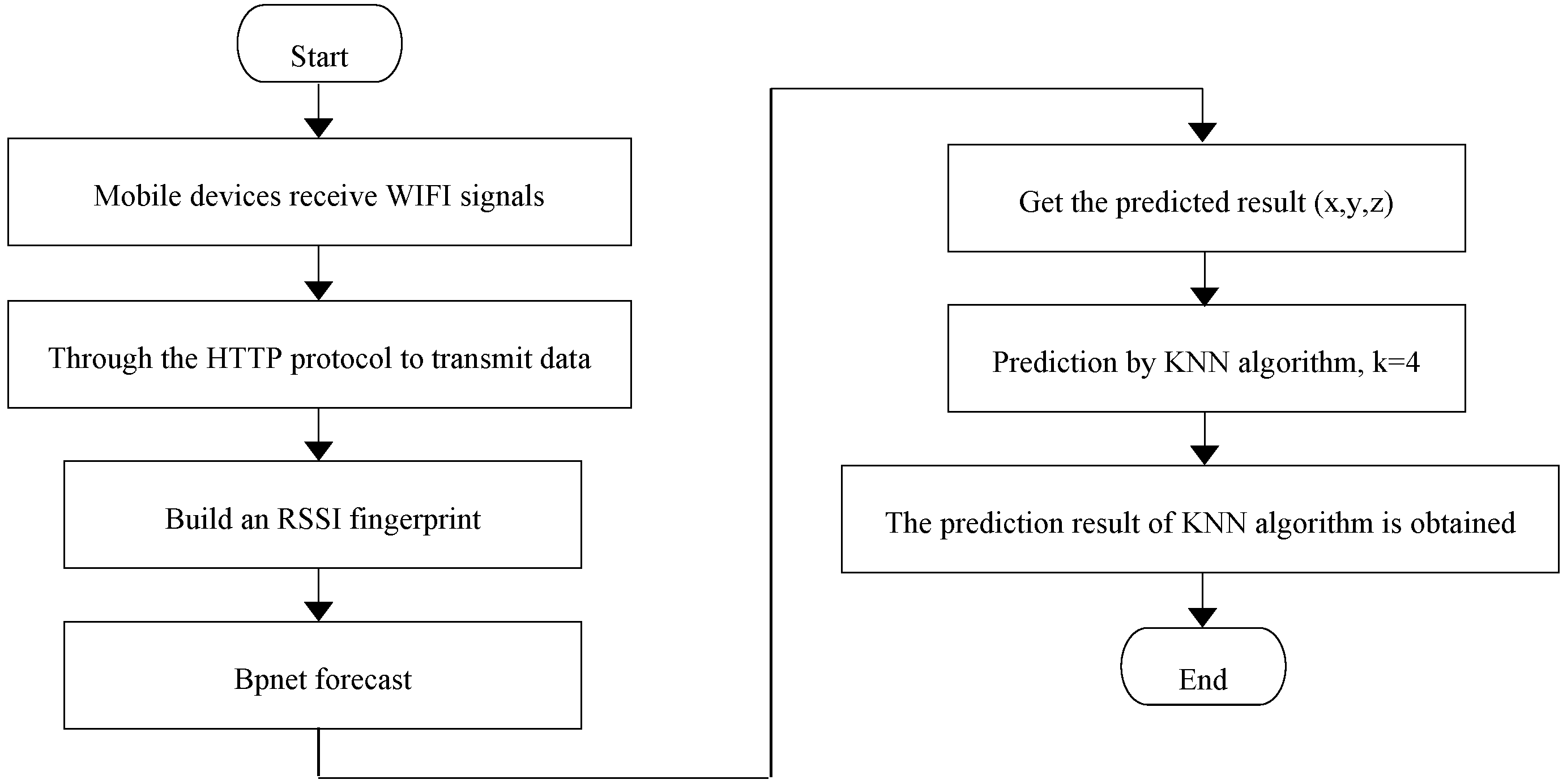
3.2.1. WIFI Fingerprint Database Positioning Technology
- (1)
- Off-line phase
- (2)
- On-line phase
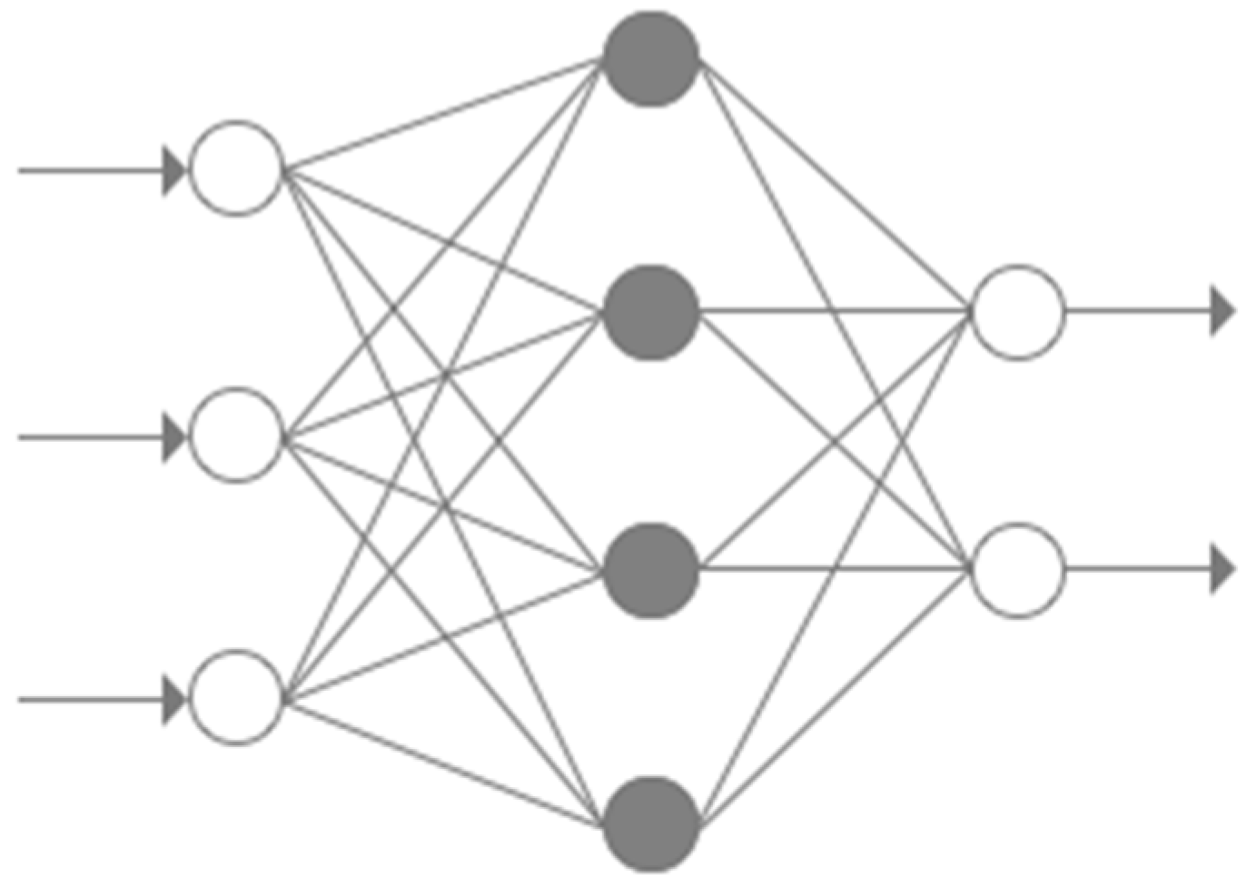
3.2.2. BP Neural Network
- (1)
- Network structure and principle
- (2)
- Model hyperparameters
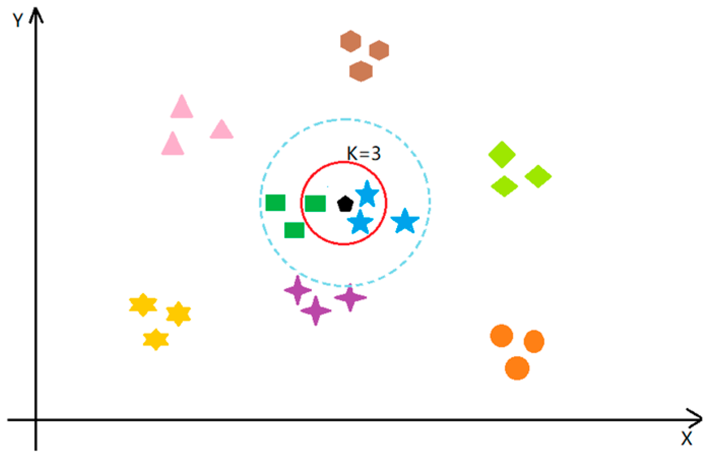
3.2.3. KNN Algorithm
3.2.4. Simulation Map Generation
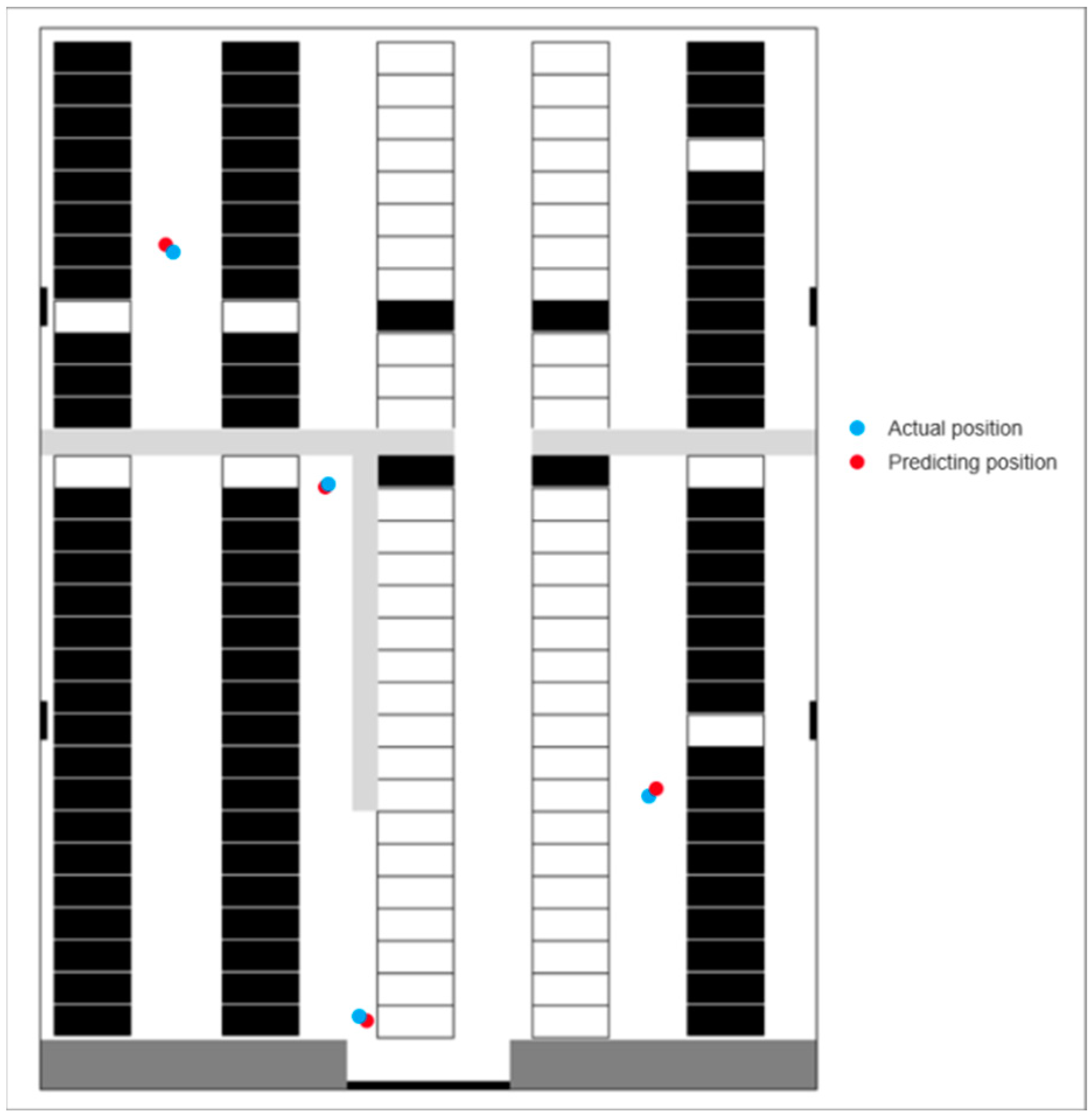
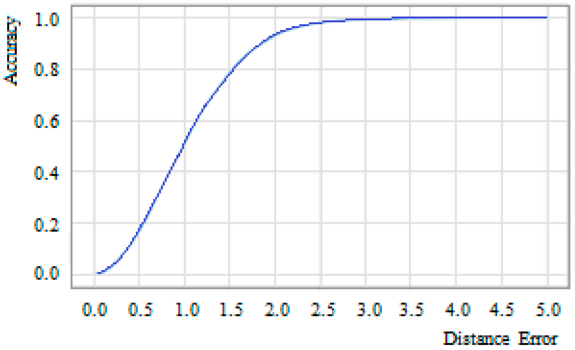
3.2.5. Simulation Result and Analysis
3.3. Path Planning Service Module
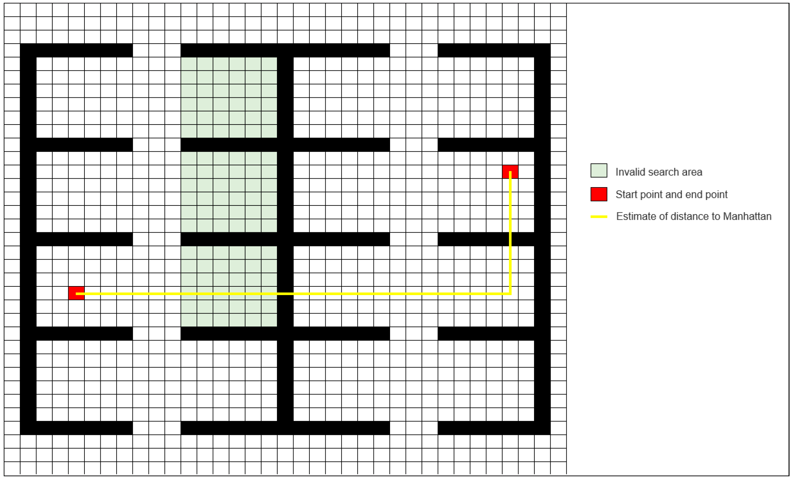
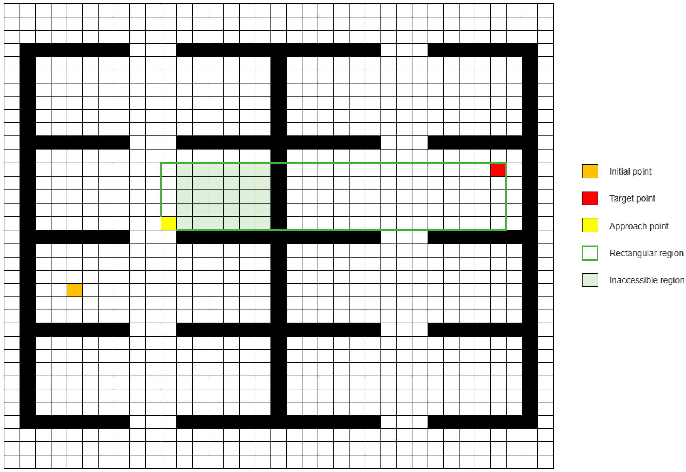
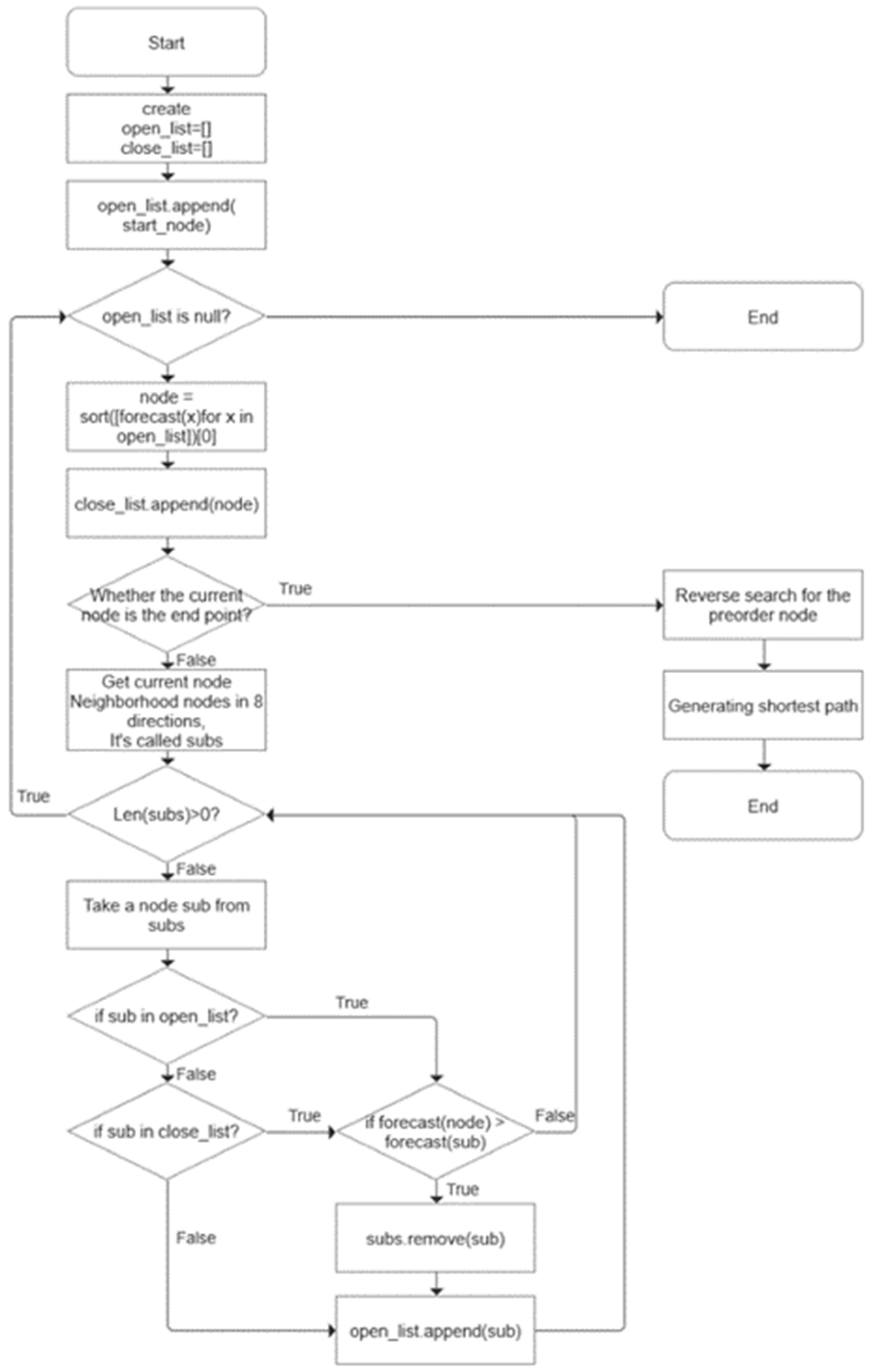
3.3.1. Improved A* Algorithm
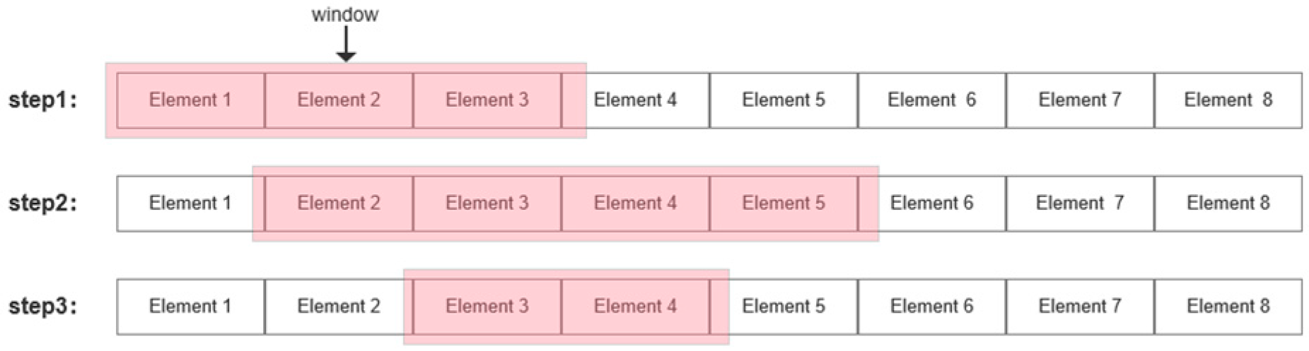
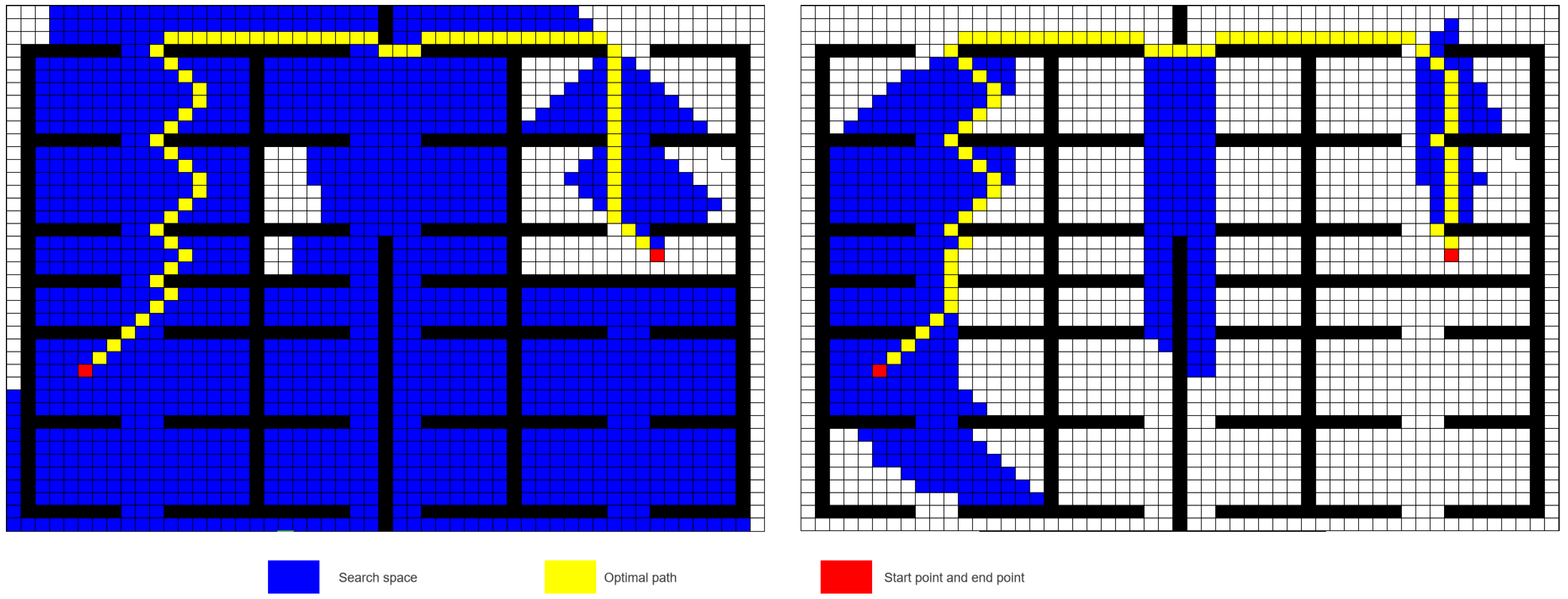
3.3.2. The Correction of Path
- Initialize the window with length 1 and contain only the first node in the A* result path.
- In the current window, whether there is an element with the same horizontal and vertical coordinates as the first element in the window.
- If so, whether the nodes between two nodes with equal horizontal and vertical coordinates are all reachable.
- (1)
- If all can be reached, update the result path in the window according to the straight line on the left of the horizontal and vertical, move the position of the window, and take the rightmost position of the current window as the starting position of the next window
- (2)
- If an unreachable point exists, maintain the original path and go to Step 4.
- If no, expand the window backward and repeat steps 2 and 3.
- When the starting node of the sliding window is the end point of the A* algorithm, the algorithm is cut off and the path update is completed.
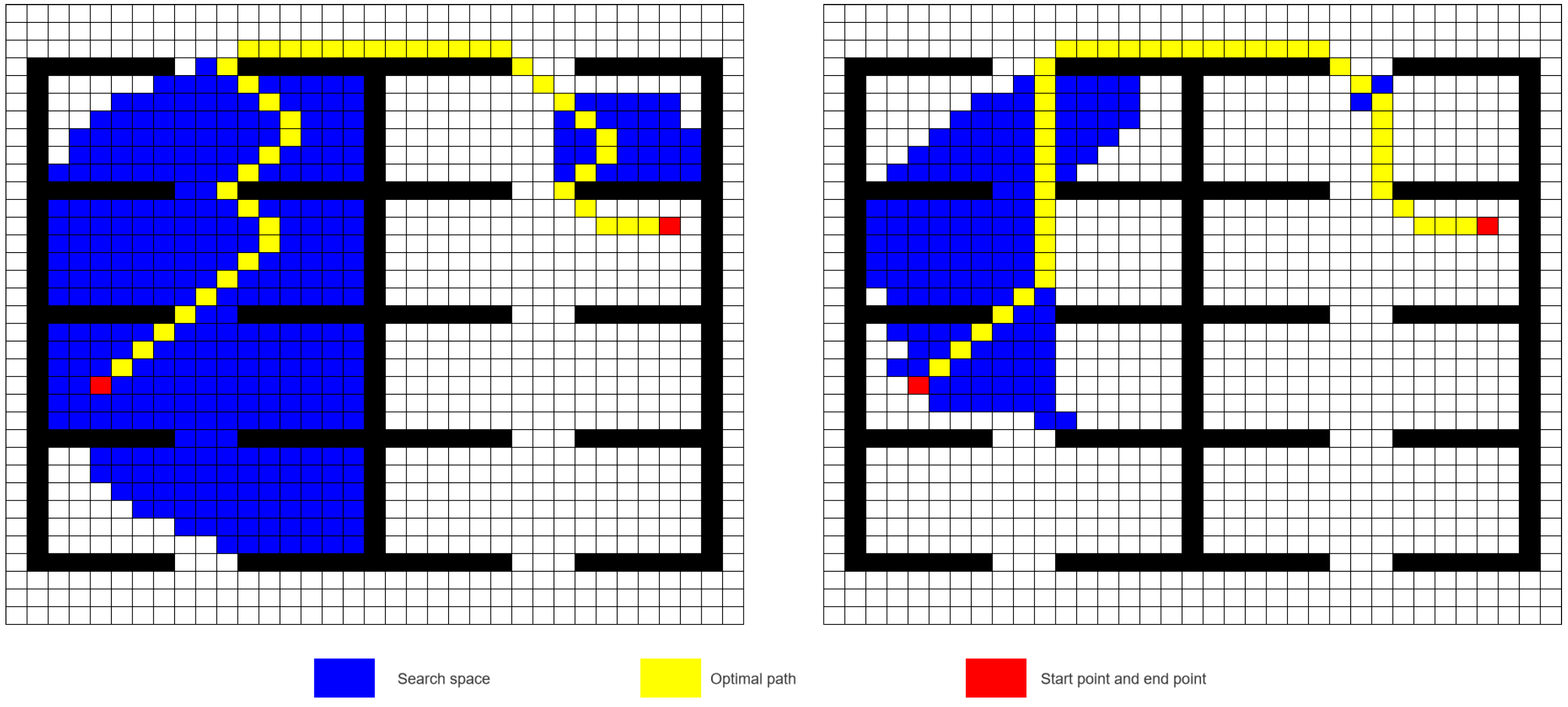
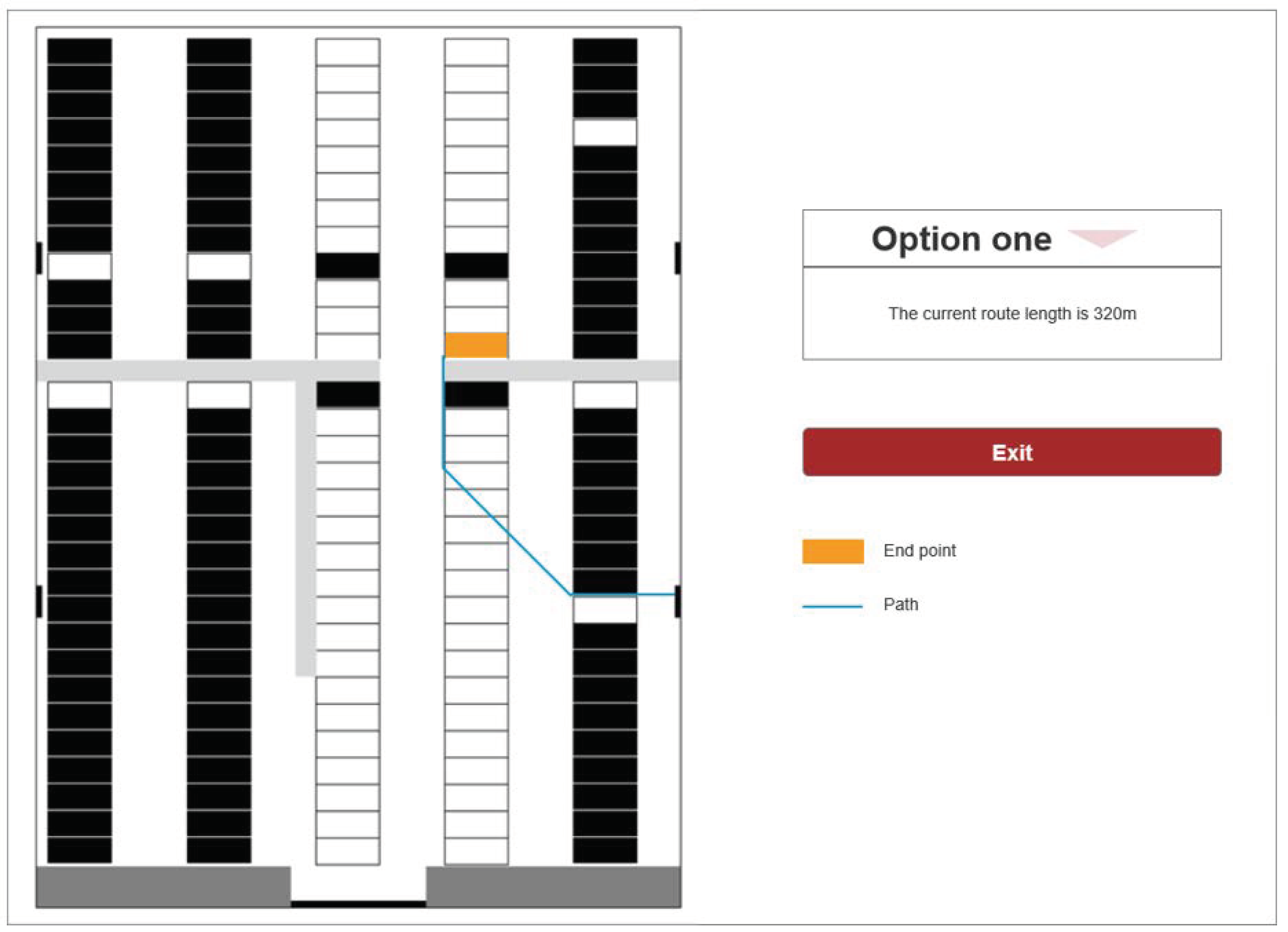
3.3.3. Simulation Results
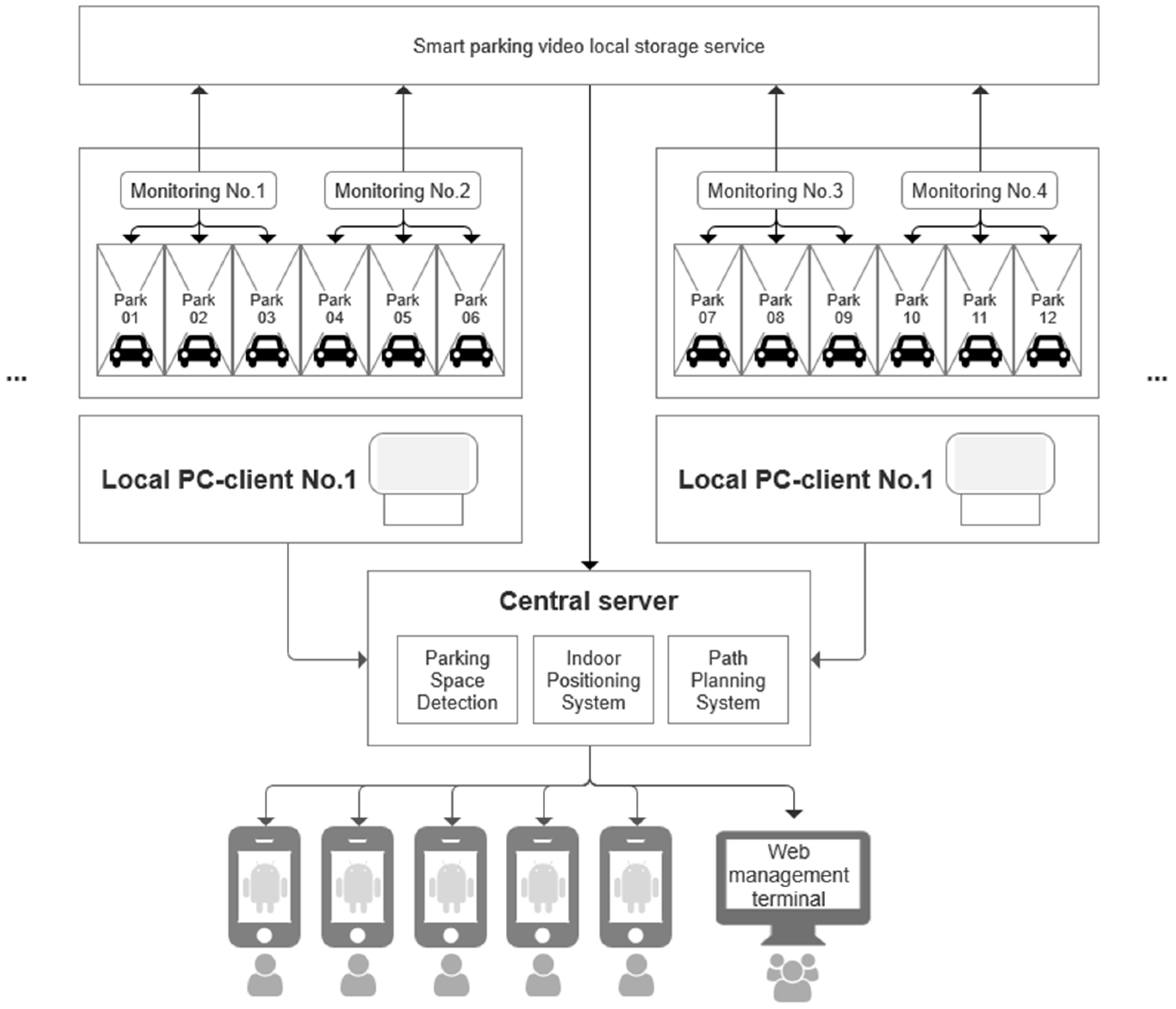
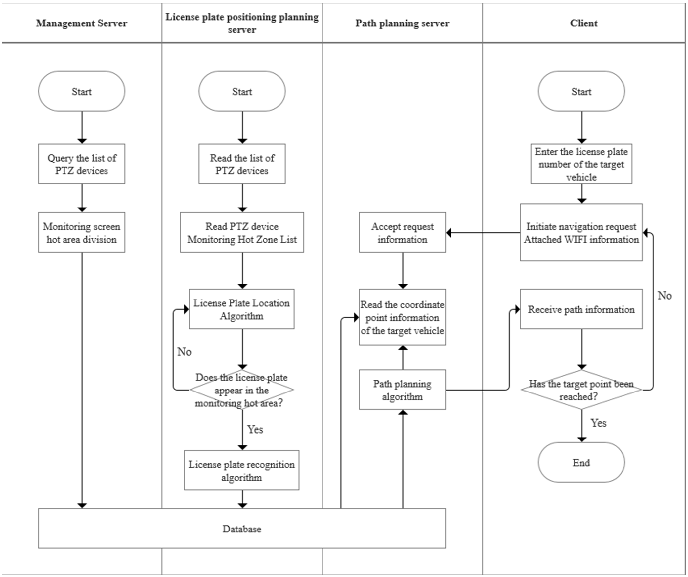
4. System Design
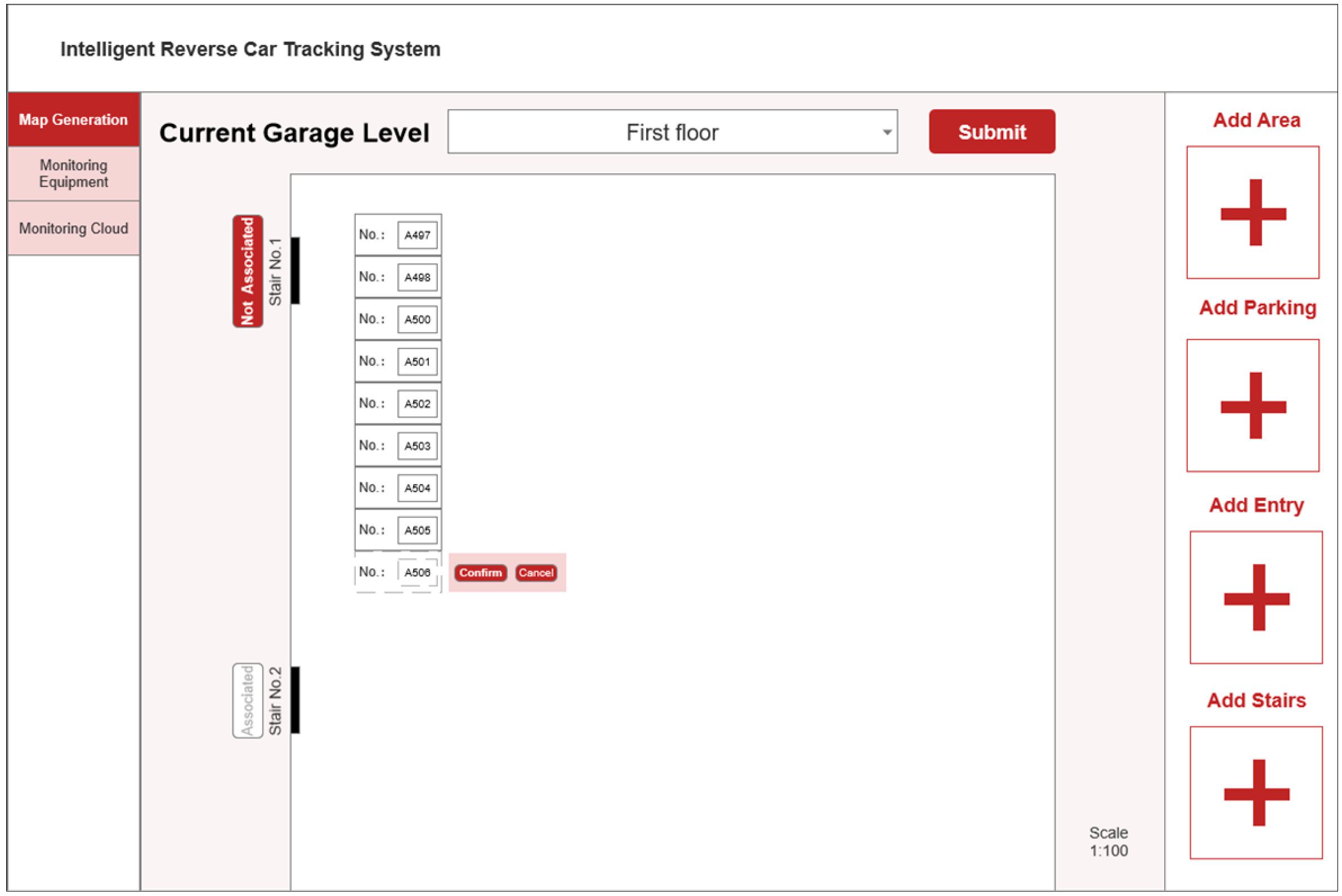
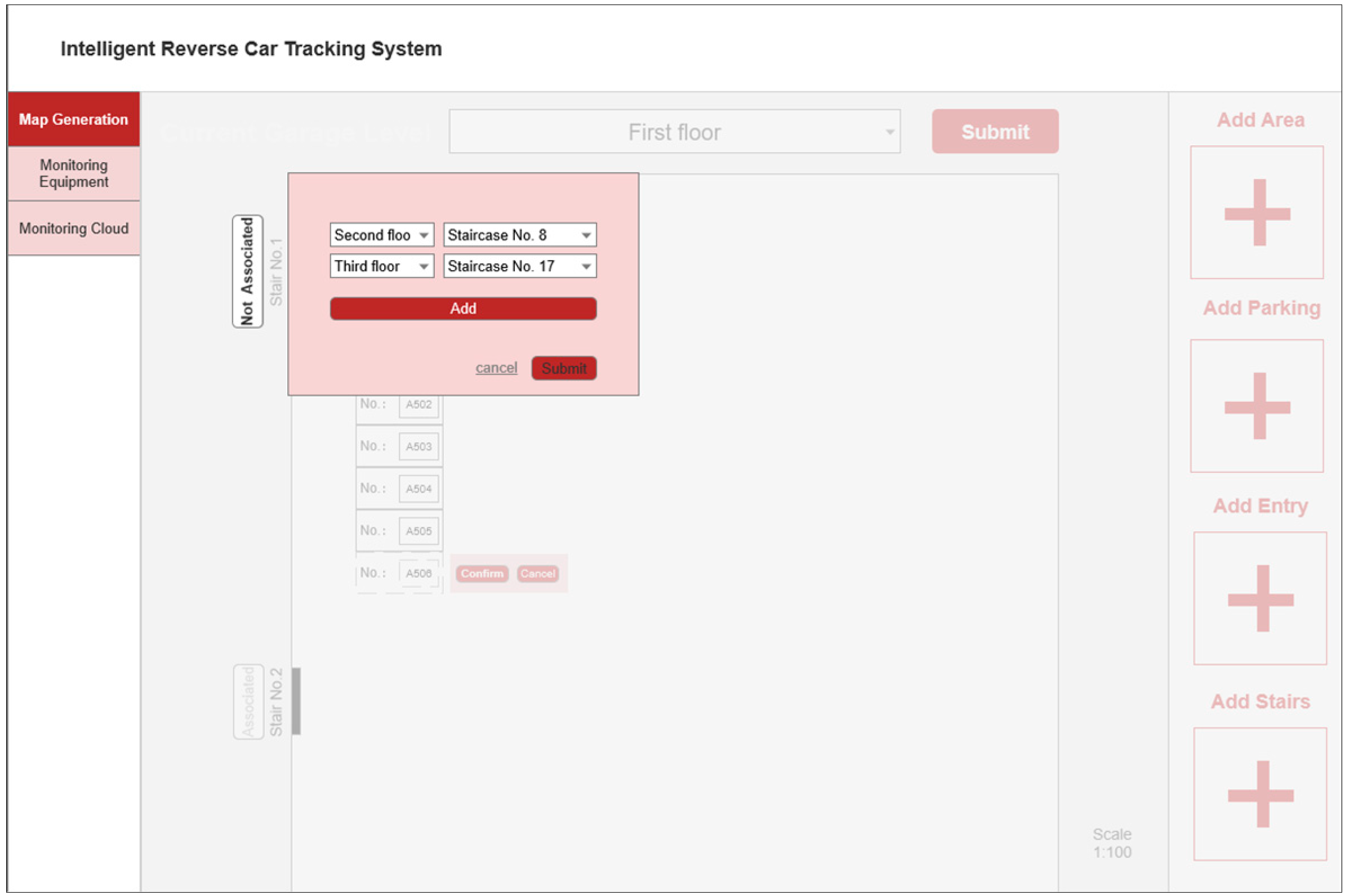
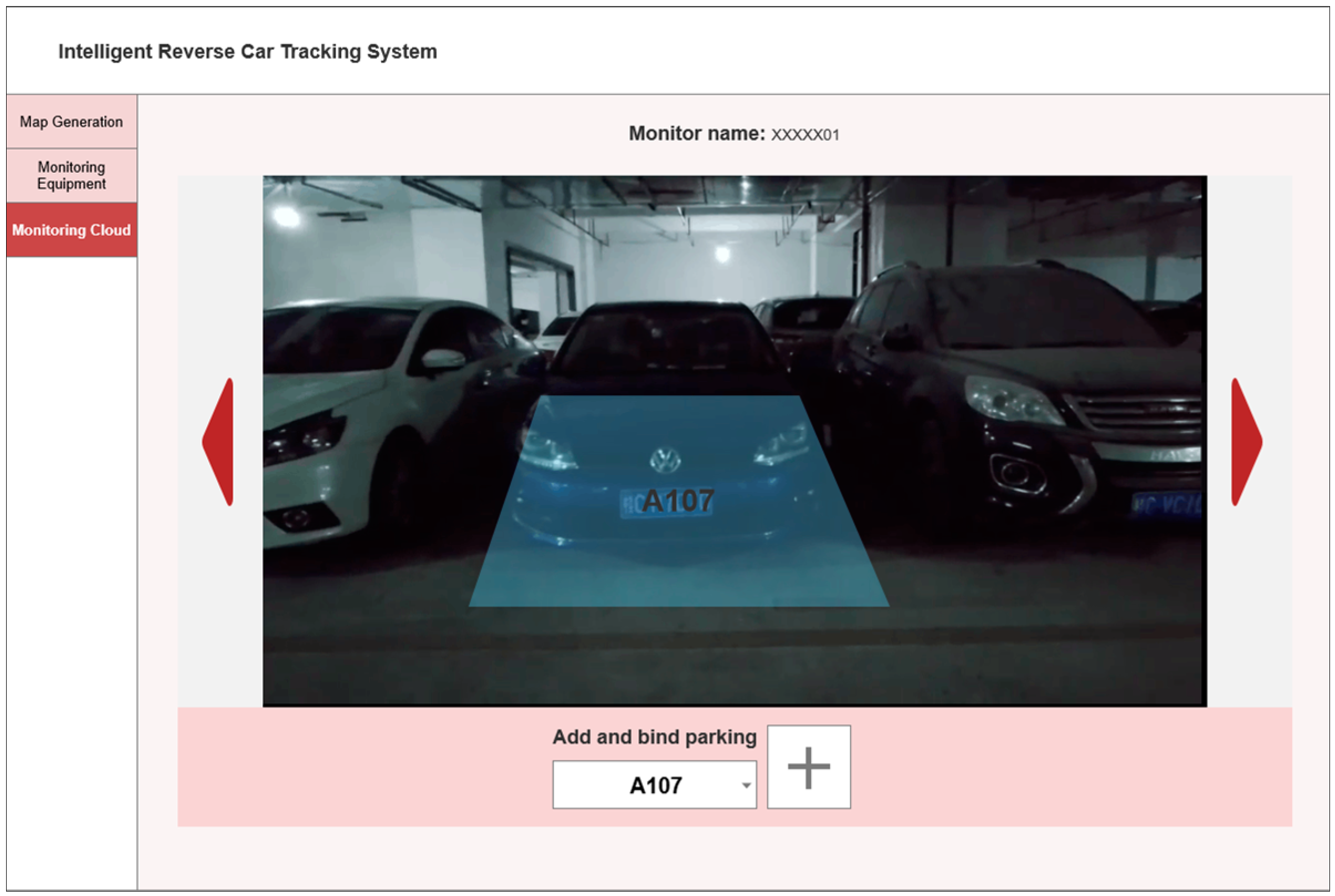
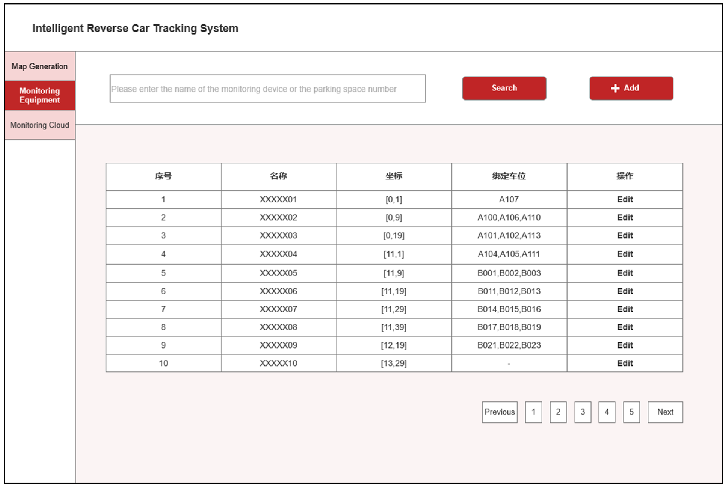
4.1. Management Side Design
4.2. Client Side Design
4.2.1. PC-Client Design
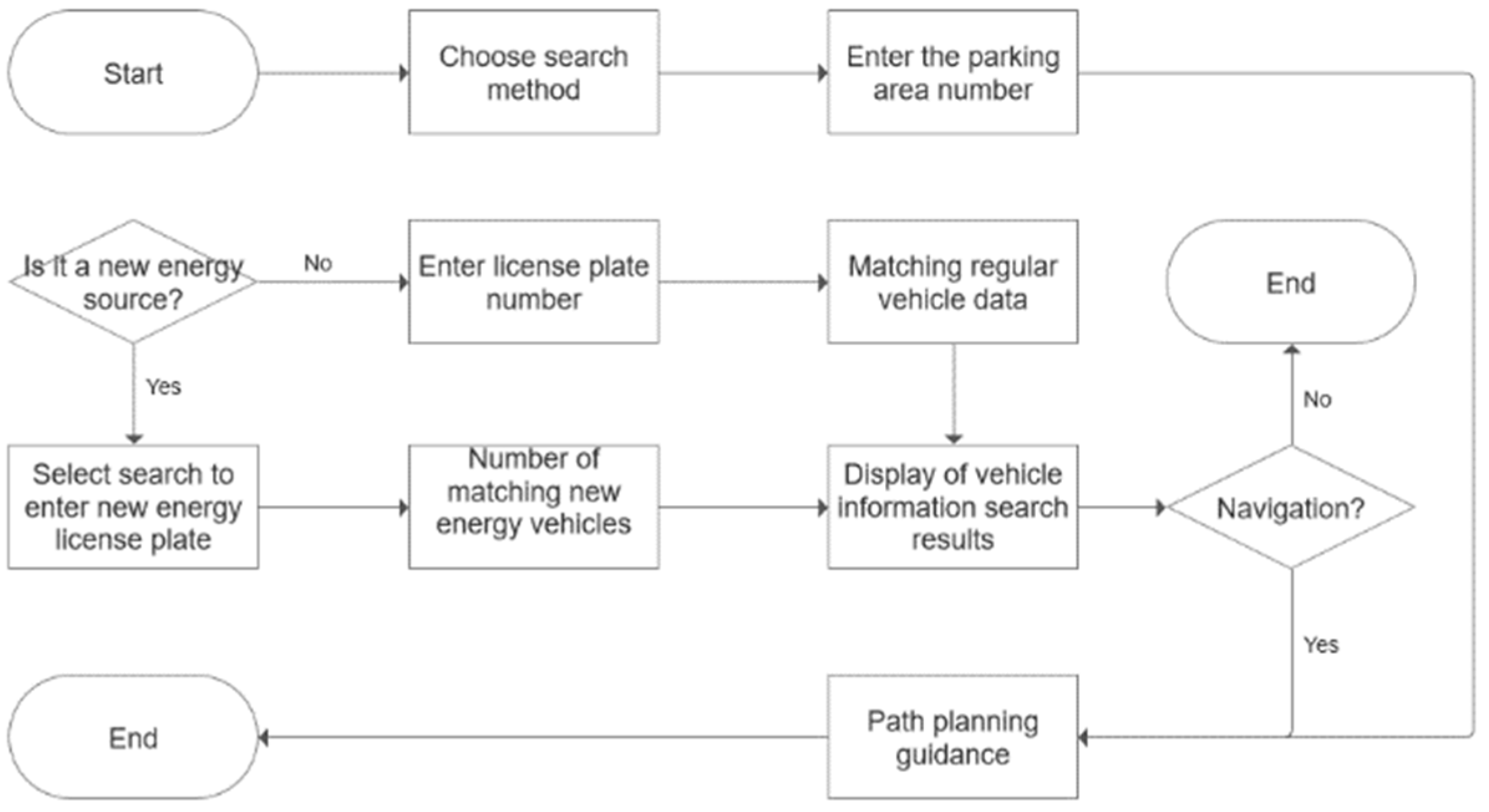
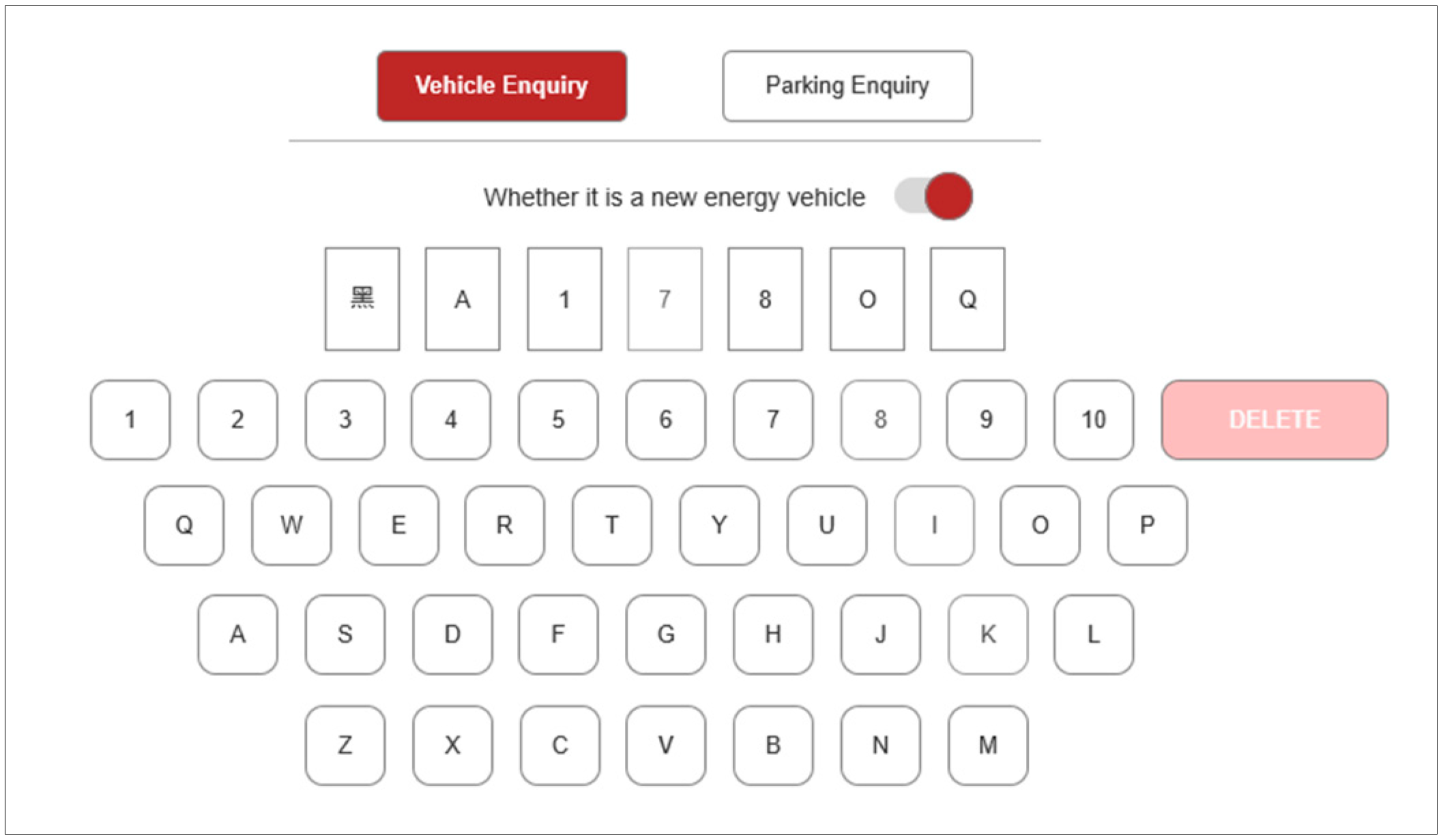
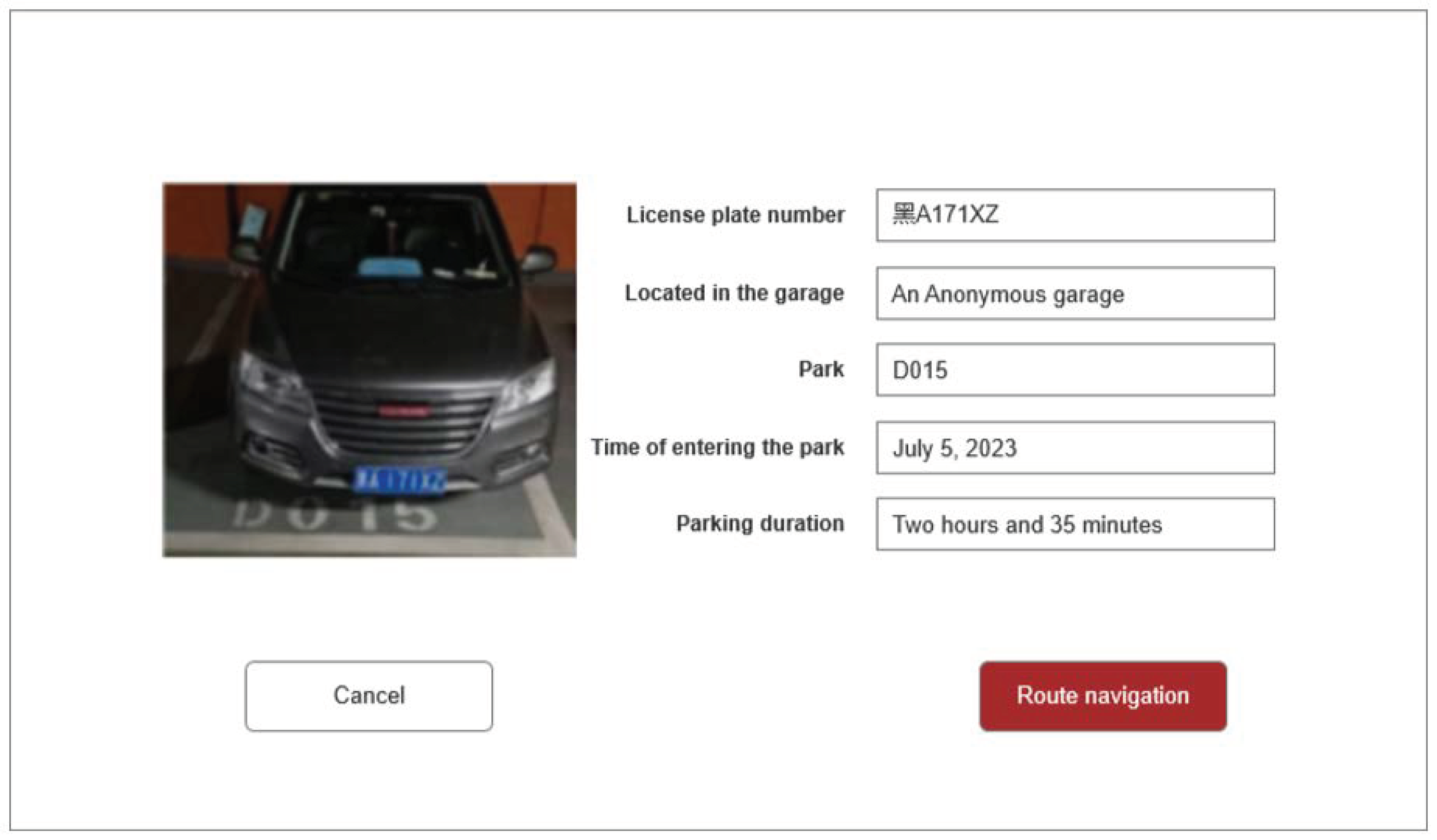
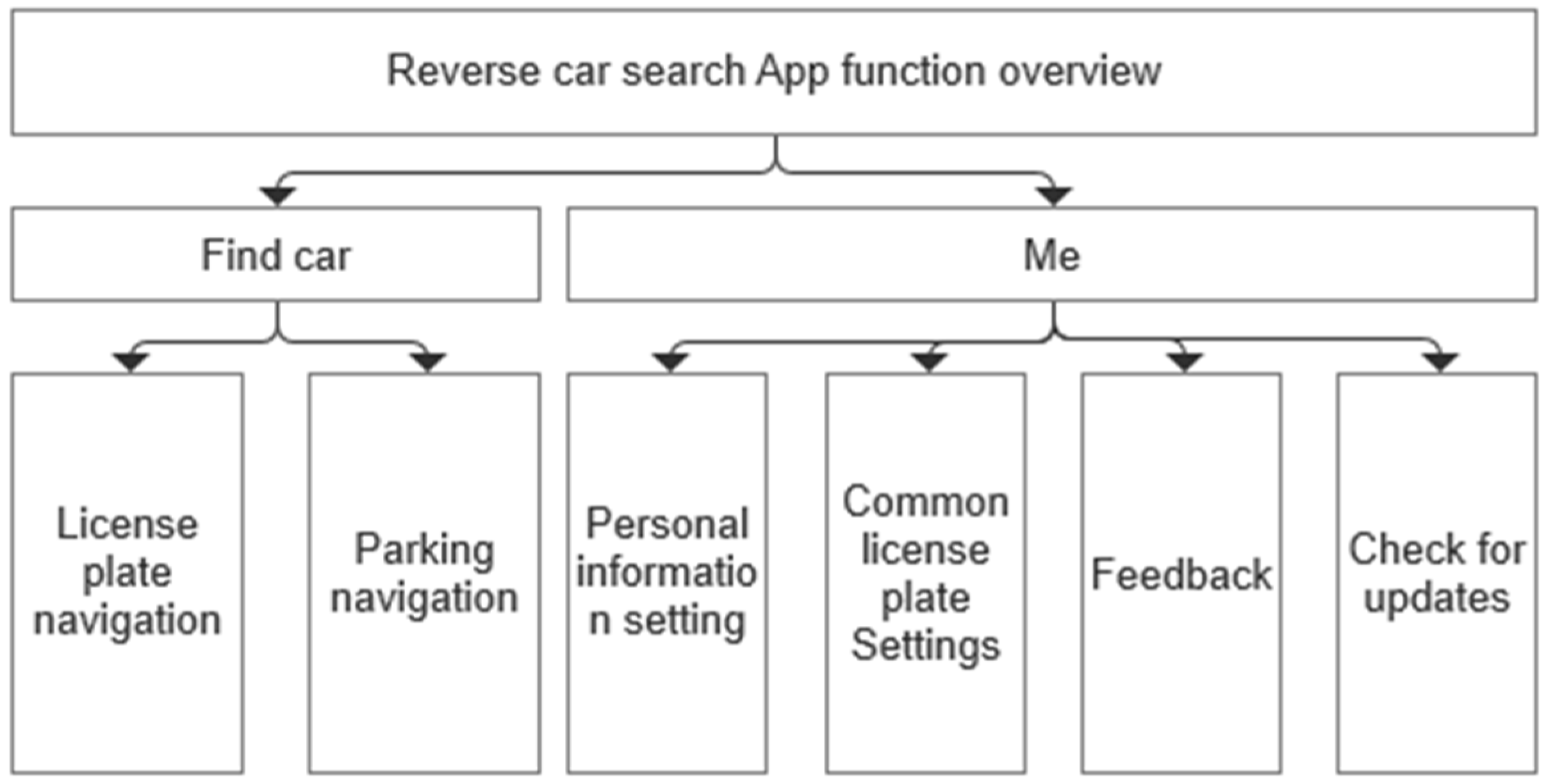
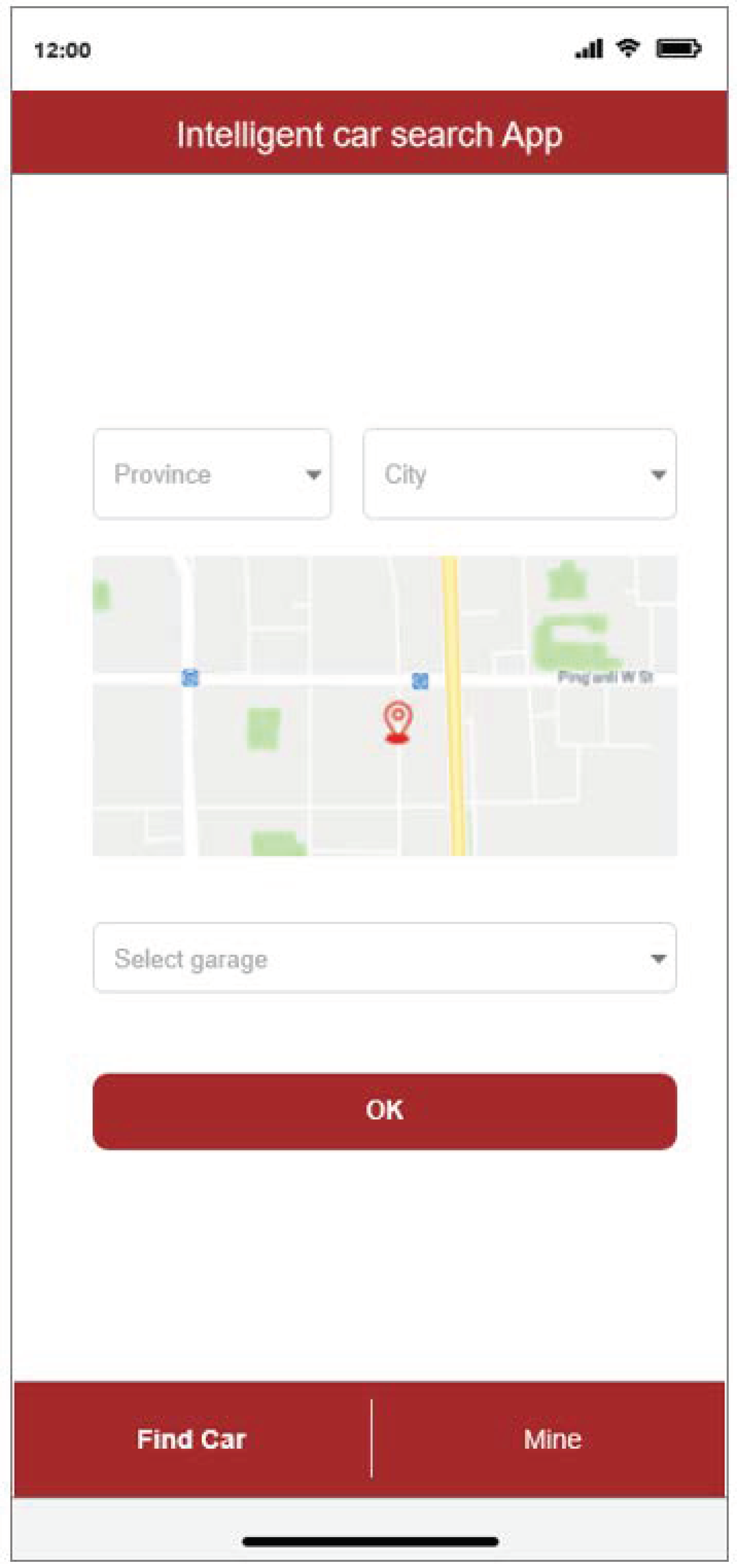
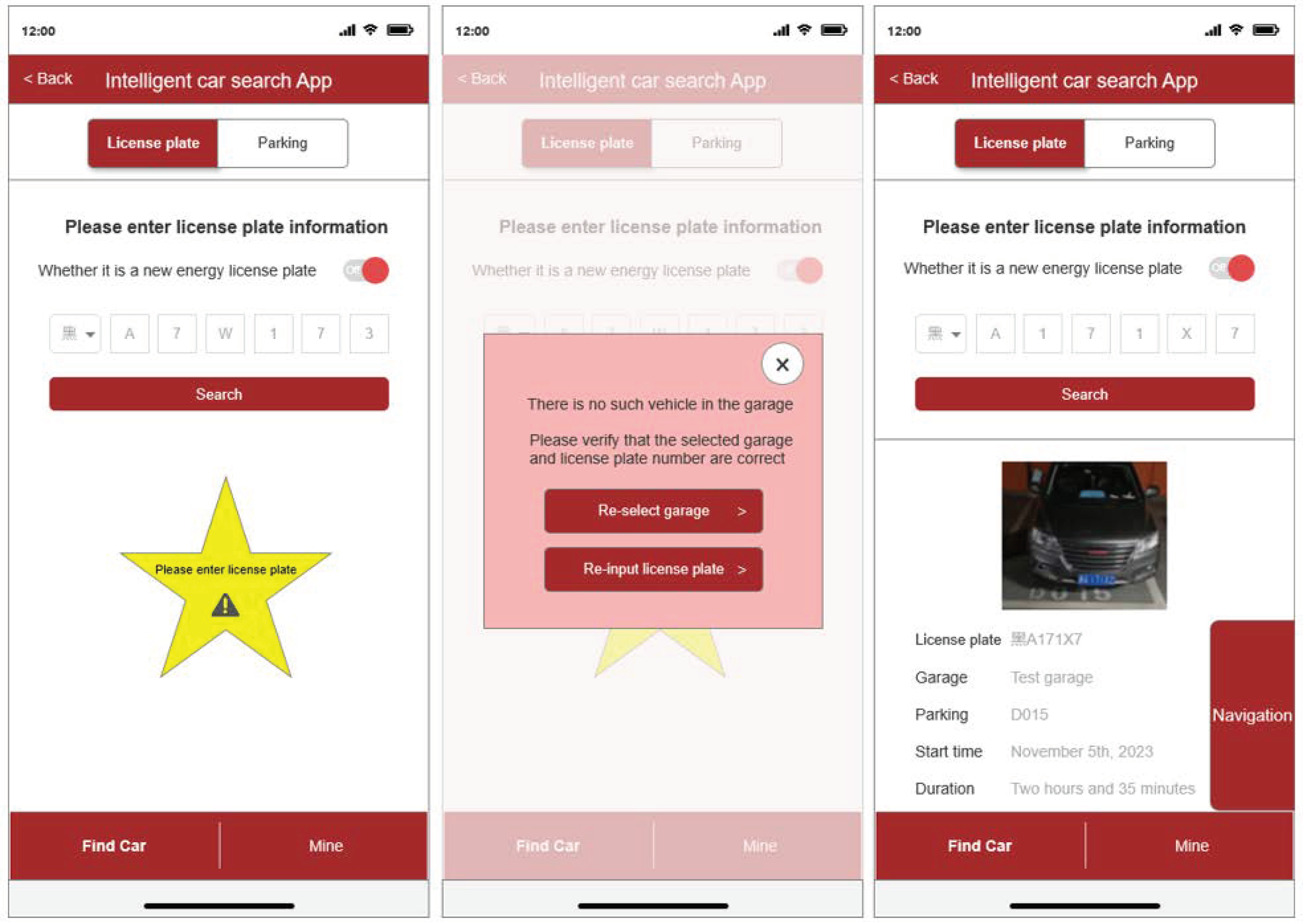
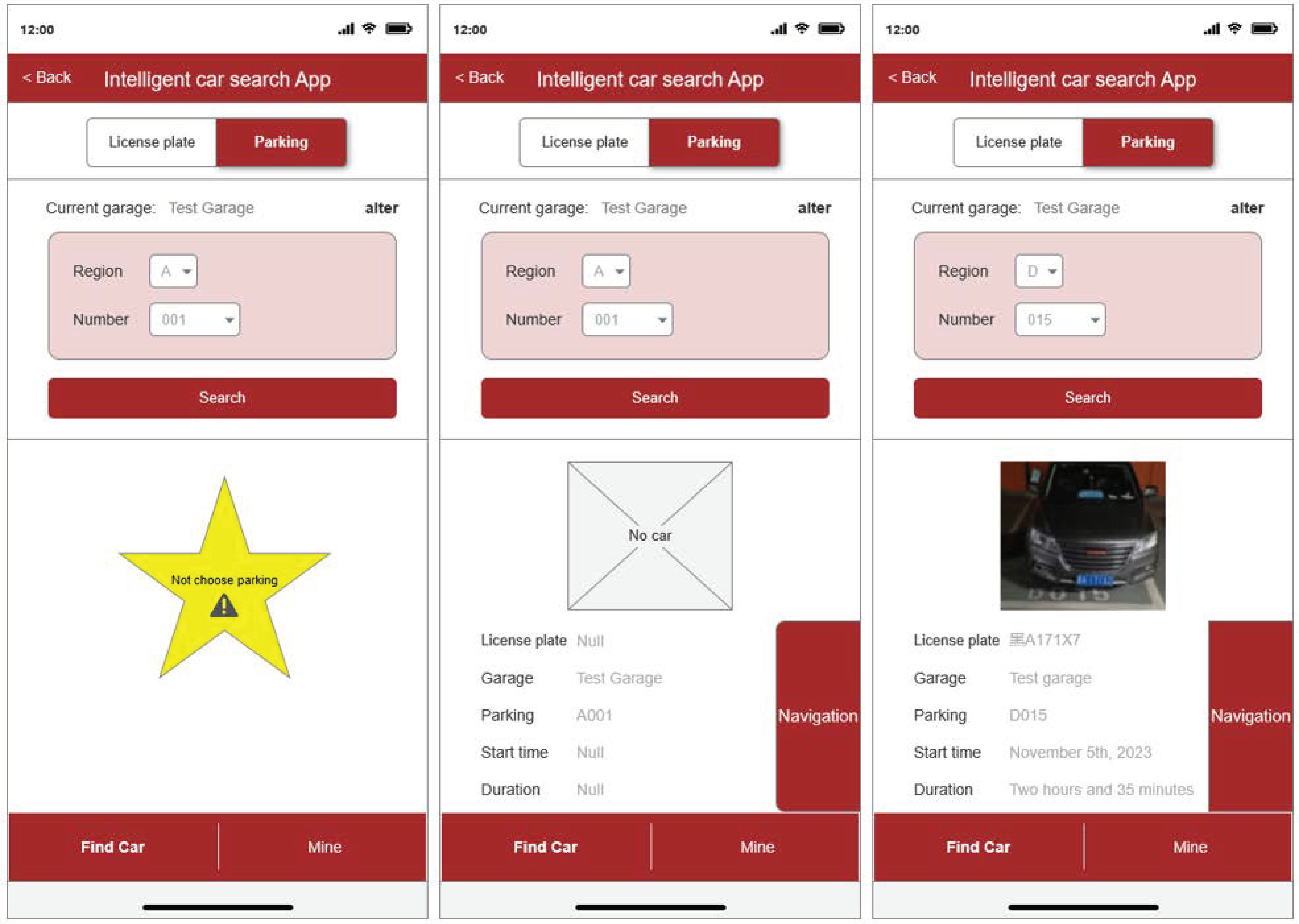
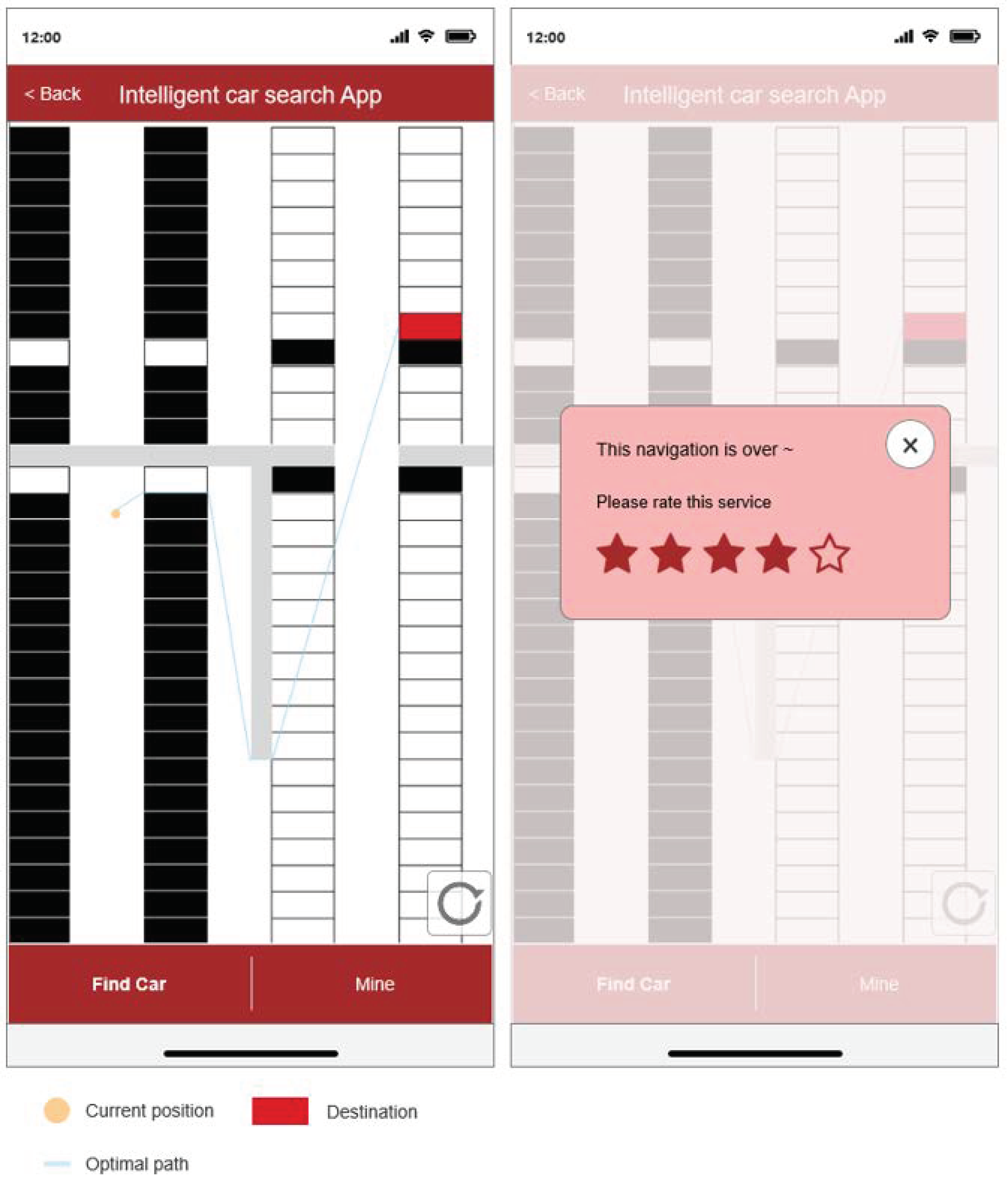
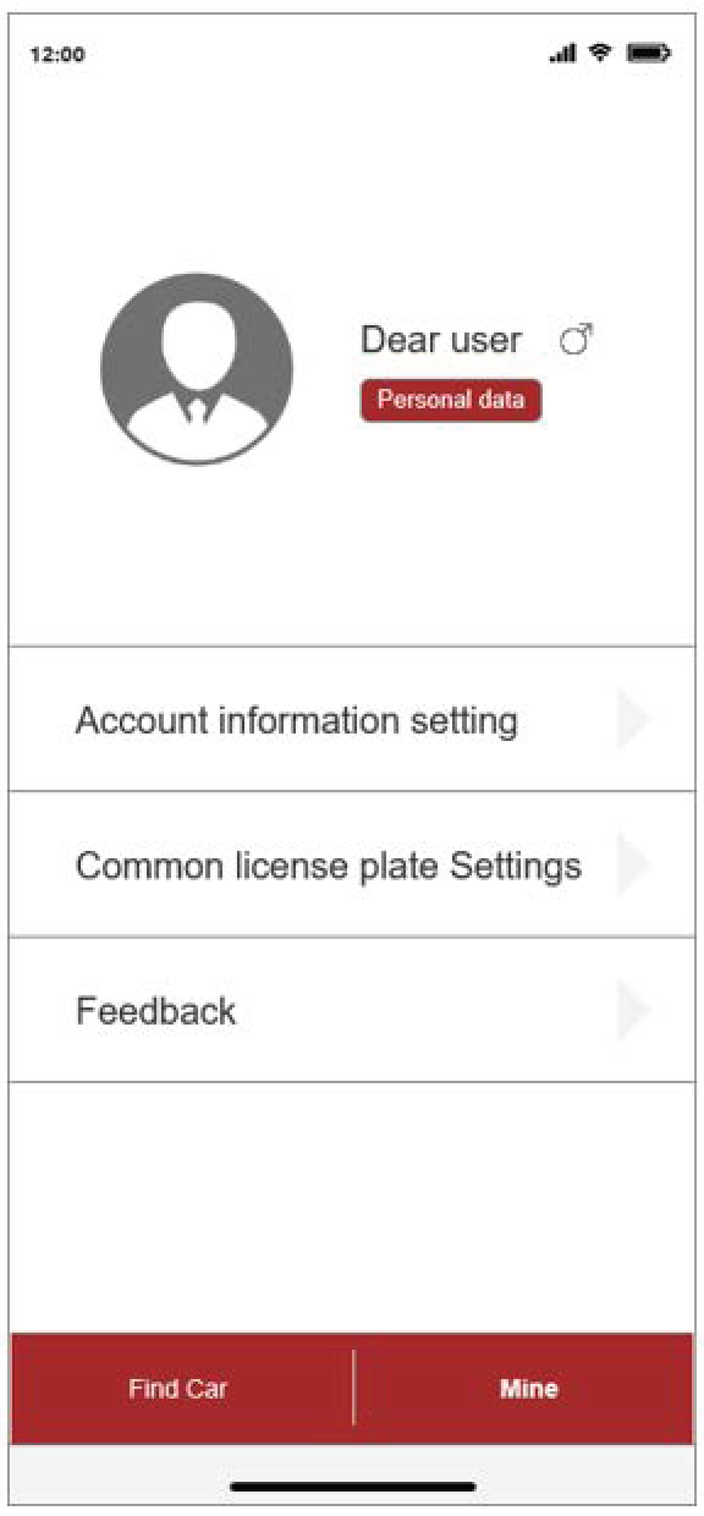
4.2.2. Mobile Design
5. Conclusions
Author Contributions
Funding
Data Availability Statement
Conflicts of Interest
References
- Ge, Y.; Yu, B. Coordinated Development of 5G Connected Vehicles and Intelligent Transportation. Constr. Sci. Technol. 2022, 1, 67–70+76. [Google Scholar] [CrossRef]
- Wang, Q.; Li, D. Development and future trend analysis of digital transformation for using of vehicles in life. Auto Maint. Repair 2023, 13, 1–8. [Google Scholar] [CrossRef]
- Jiao, J.; Yan, C.; Gou, Q.; Shi, W.; He, B.; Shang, Z. Reverse car searching system for large and medium sized parking with mode of internet and smart model. New Technol. New Prod. China 2022, 23, 22–24+35. [Google Scholar] [CrossRef]
- Sun, K.; Wang, H. Design of parking guidance system for large underground parking. Agric. Equip. Veh. Eng. 2021, 59, 144–147. [Google Scholar] [CrossRef]
- Wang, C. Talking about development of history and product technology of parking lot. China Public Secur. 2017, 1, 138–141. [Google Scholar]
- Zhao, H.; Ma, S.; Li, J.; Li, Y.; Xue, W. Parking guidance system and reversed car locating intelligent system in large parking lots. Mod. Archit. Electr. 2016, 7, 43–47. [Google Scholar] [CrossRef]
- Chen, T. Vehicle Positioning Based on Vehicle Re-Identification and Pedestrian Navigation for Reverse Vehicle Searching Systems. Master’s Thesis, Huazhong University of Science and Technology, Wuhan, China, 2022. [Google Scholar]
- Wang, J. Vehicle location system for indoor parking lot based on LoRa. J. Guangxi Minzu Univ. (Nat. Sci. Ed.) 2023, 29, 97–101. [Google Scholar]
- Yan, X. Study on Localization and Semantic Mapping Technology of Vehicle in the Indoor Parking Lot. Master’s Thesis, Chongqing University, Chongqing, China, 2021. [Google Scholar]
- Mao, G.; Zhang, Y.; Zhao, H. An optimal parking path planning and design for a parking lot. Value Eng. 2024, 43, 997–999. [Google Scholar]
- Yang, P. Car searching technology of parking lot. China Secur. Prot. 2013, 3, 46–50. [Google Scholar]
- Zhang, H.; Yang, B.; Dai, C.; Tian, Y.; Zhang, Y. Design and research of city-level intelligent parking management system. Intell. Build. Smart City 2024, 1, 170–172. [Google Scholar] [CrossRef]
- Jie, H.; Liu, K.; Zhang, H.; Xie, R.; Wu, W.; Guo, S. AODC: Automatic offline database construction for indoor localization in a hybrid UWB/Wi-Fi environment. In Proceedings of the 2020 IEEE/CIC International Conference on Communications in China (ICCC), Chongqing, China, 9–11 August 2020. [Google Scholar]
- Chen, W.; Ji, Z.; Xiao, H.; Wang, H. Analysis of motor vehicle ownership in China. Environ. Prot. 2017, 45, 33–34. [Google Scholar]
- Yin, H.; Xu, C. Design of logistics parking lot guidance system based on image recognition. China Storage Transp. 2024, 1, 182. [Google Scholar] [CrossRef]
- Li, X. Analysis of application strategy of automatic car finding technology in automotive intelligent network connection system. Auto Time 2023, 5, 19–21. [Google Scholar]
- Lin, B.; Bai, J.; Zeng, P.; Guo, K.; Zhang, T. Intelligent and benefit parking platform design based on 5G and AR technology for Fuzhou urban. Light Ind. Sci. Technol. 2023, 39, 97–100+132. [Google Scholar]
- Fang, Z.; Wang, J.; He, Y. Discussion on the implementation of parking and car researing guidance system. Green Constr. Intell. Build. 2014, 4, 40–46. [Google Scholar]
- Shin, J.-H.; Jun, H.-B.; Kim, J.-G. Dynamic control of intelligent parking guidance using neural network predictive control. J. Comput. Ind. Eng. 2018, 120, 15–30. [Google Scholar] [CrossRef]
- Wang, T.; Zhu, Y.; Jin, L.; Luo, C.; Chen, X.; Wu, Y.; Wang, Q.; Cai, M. Decoupled attention network for text recognition. In Proceedings of the AAAI 2020-34th AAAI Conference on Artificial Intelligence, New York, NY, USA, 7–12 February 2020. [Google Scholar]
- Tokuyoshi, Y.; Iwasaki, S. Development and psychometric evaluation of a Japanese version of the Personal Growth Initiative Scale-II. Jpn. J. Psychol. 2014, 85, 178–187. [Google Scholar] [CrossRef]
- Zhao, Y. Design of Reserve Car-Searching System and Research on Path Planning Algorithm for Large Underground Parking Lots. Master’s Thesis, Harbin University of Science and Technology, Harbin, China, 2022. [Google Scholar] [CrossRef]
- Biswas, D.; Barai, S.; Sau, B. New RSSI-fingerprinting-based smartphone localization system for indoor environments. Wirel. Netw. 2023, 29, 1281–1297. [Google Scholar] [CrossRef]
- Arigye, W.; Pu, Q.; Zhou, M.; Khalid, W.; Tahir, M.J. RSSI fingerprint height based empirical model prediction for smart indoor localization. Sensors 2022, 22, 9054. [Google Scholar] [CrossRef] [PubMed]
- Wang, R.; Lu, Z.; Jin, Y.; Liang, C. Application of A* algorithm in intelligent vehicle path planning. Math. Models Eng. 2022, 8, 82–90. [Google Scholar] [CrossRef]
- Li, Z.; Shi, R.; Zhang, Z. A new path planning method based on sparse A* algorithm with map segmentation. Trans. Inst. Meas. Control 2022, 44, 916–925. [Google Scholar]
- Li, X.; Meng, L.; Wang, J.; Xue, Z. Design of parking space management system of multistory parking area based on ZigBee. Comput. Digit. Eng. 2022, 50, 1624–1629. [Google Scholar] [CrossRef]
- Laroca, R.; Severo, E.; Zanlorensi, L.A.; Oliveira, L.S.; Gonçalves, G.R.; Schwartz, W.R.; Menotti, D. A robust real-time automatic license plate recognition based on the YOLO detector. In Proceedings of the 2018 International Joint Conference on Neural Networks (IJCNN 2018), Rio de Janeiro, Brazil, 8–13 July 2018. [Google Scholar]
- Chen, R.C. Automatic license plate recognition via sliding-window darknet-YOLO deep learning. Image Vis. Comput. 2019, 87, 47–56. [Google Scholar] [CrossRef]
- Li, H.; Wang, P.; Shen, C. Toward End-to-End car license plate detection and recognition with deep neural networks. IEEE Trans. Intell. Transp. Syst. 2019, 20, 1126–1136. [Google Scholar] [CrossRef]
- Zheng, A.; Qin, N. Indoor localization algorithm with dual refinement of spacial fingerprint measurement features. Chin. J. Sci. Instrum. 2023, 44, 80–89. [Google Scholar]
- Ghaffarian, H. Reducing search area in indoor localization applications. Wirel. Pers. Commun. 2021, 117, 1243–1258. [Google Scholar] [CrossRef]
- Guo, X.; Li, L.; Ansari, N.; Liao, B. Accurate WiFi localization by fusing a group of fingerprints via a global fusion profile. IEEE Trans. Veh. Technol. 2018, 67, 7314–7325. [Google Scholar] [CrossRef]
- Rempel, P.; Borisov, A. Local system of positioning using a WiFi network. In Proceedings of the 8th International Scientific and Practical Conference on Information and Measuring Equipment and Technologies, IME and T 2017, Tomsk, Russia, 22–25 November 2017. [Google Scholar] [CrossRef]
- Altahan, M.F.; Nower, M. AutoGIS processing for site selection for solar pond development as efficient water treatment plants in Egypt. Sci. Rep. 2023, 13, 17009. [Google Scholar] [CrossRef] [PubMed]
- Ye, X.; Zhong, H.; Deng, K. A path planning method of indoor navigation based on improved A-Star algorithm. Comput. Technol. Dev. 2022, 32, 202–206. [Google Scholar]
- Wang, J.; Su, Y.; Yao, J.; Liu, M.; Du, Y.; Wu, X.; Huang, L.; Zhao, M. Apple rapid recognition and processing method based on an improved version of YOLOv5. Ecol. Inform. 2023, 77, 102196. [Google Scholar] [CrossRef]
- Duan, Y.; Qiu, S.; Jin, W.; Lu, T.; Li, X. High-Speed rail tunnel panoramic inspection image recognition technology based on improved YOLOv5. Sensors 2023, 23, 5986. [Google Scholar] [CrossRef]
- Wang, Z.; Jiang, Y.; Liu, J.; Gong, S.; Yao, J.; Jiang, F. Research and implementation of Fast-LPRNet algorithm for license plate recognition. J. Electr. Comput. Eng. 2021, 2021, 8592216. [Google Scholar] [CrossRef]
- Shi, Y.-T.; Zhang, H.; Tao, Z.; Guo, W. License plate recognition based on YOLOv5-LPRNet. In Proceedings of the 2022 4th International Conference on Intelligent Information Processing (IIP), Guangzhou, China, 14–16 October 2022. [Google Scholar] [CrossRef]
- Xiao, X.; Chang, H.; Tang, K.; Zou, J.; Cai, Y. Research on license plate recognition algorithm based on YOLOv5 and LPRNet. In Proceedings of the 2023 IEEE 3rd International Conference on Software Engineering and Artificial Intelligence (SEAI), Xiamen, China, 16–18 June 2023. [Google Scholar] [CrossRef]
- Huang, G.; Hu, Z.; Cai, H. Wi-fi and vision integrated localization for reverse vehicle-searching in underground parking lot. In Proceedings of the 2017 4th International Conference on Transportation Information and Safety (ICTIS 2017), Banff, AB, Canada, 8–10 August 2017. [Google Scholar] [CrossRef]
- Tang, S.L.; Tang, H.; Guo, H. Stability evaluation of empty mine goaf based on BP neural network. J. Xi’an Univ. Sci. Technol. 2012, 32, 234–238+258. [Google Scholar]
- Pustokhina, I.V.; Pustokhin, D.A.; Rodrigues, J.J.; Gupta, D.; Khanna, A.; Shankar, K.; Seo, C.; Joshi, G.P. Automatic vehicle license plate recognition using optimal K-means with convolutional neural network for intelligent transportation systems. IEEE Access 2020, 8, 92907–92917. [Google Scholar] [CrossRef]
- Li, Y.; He, H.; Hou, F. Crowd-sourced optical indoor positioning updated by WiFi fingerprint localization. In Proceedings of the Fifteenth International Conference on Machine Vision, Rome, Italy, 18–20 November 2022. [Google Scholar] [CrossRef]
- Dong, Y.; Arslan, T.; Yang, Y.; Ma, Y. A WiFi fingerprint augmentation method for 3-D crowd sourced indoor positioning systems. In Proceedings of the 2022 IEEE 12th International Conference on Indoor Positioning and Indoor Navigation (IPIN), Beijing, China, 5–7 September 2022. [Google Scholar] [CrossRef]
- Magsino, E.; Barrameda JM, C.; Puno, A.; Ong, S.; Siapco, C.; Vibal, J. Determining commercial parking vacancies employing multiple WiFi RSSI fingerprinting method. J. Sens. Actuator Netw. 2023, 12, 22. [Google Scholar] [CrossRef]
- Zheng, Y.; Lv, X.; Qian, L.; Liu, X. An optimal BP neural network track prediction method based on a GA–ACO hybrid algorithm. J. Mar. Sci. Eng. 2022, 10, 1399. [Google Scholar] [CrossRef]
- Chen, J.; Liu, Z.; Yin, Z.; Liu, X.; Li, X.; Yin, L.; Zheng, W. Predict the effect of meteorological factors on haze using BP neural network. Urban Clim. 2023, 51, 101630. [Google Scholar] [CrossRef]
- Park, K.; Oh, C.; Yi, Y. BPNet: Branch-pruned Conditional Neural Network for Systematic Time-accuracy Tradeoff. In Proceedings of the 2020 57th ACM/IEEE Design Automation Conference (DAC), San Francisco, CA, USA, 20–24 July 2020. [Google Scholar] [CrossRef]
- Zhu, X. Indoor localization based on optimized KNN. Netw. Commun. Technol. 2020, 5, 34–39. [Google Scholar] [CrossRef]
- Mac, T.T.; Copot, C.; Tran, D.T.; De Keyser, R. Heuristic approaches in robot path planning: A survey. Robot. Auton. Syst. 2016, 86, 13–28. [Google Scholar] [CrossRef]
- Shen, K.; You, Z.; Liu, Y. A multi-scene adaptive A* algorithm based on fitting-first search. Comput. Eng. Sci. 2024, 46, 142–149. [Google Scholar]


| Key | Value |
|---|---|
| img_size | [94, 24] |
| max_epoch | 200 |
| dropout_rate | 0.5 |
| UnFreeze_Epoch | 300 |
| learning_rate | 0.001 |
| lpr_max_len | 8 |
| train_batch_size | 64 |
| test_batch_size | 64 |
| weight_decay | |
| lr_schedule | [20, 40, 60, 80, 100] |
| Parameter | Settings |
|---|---|
| Batch | 64 |
| Epochs | 8000 |
| Optimizer | Adam |
| Initial Learning rate | 0.01 |
| Learning Rate Decreasing Step Size | 0.01 |
| Weight decay | 0.0005 |
| Old | New | Increase Rate | |
|---|---|---|---|
| Length of the shortest path | 45 | 45 | 0% |
| The size of the search space | 387 | 174 | 55.0% |
| Running time | 0.07 s | 0.05 s | 28.5% |
| Old | New | Increase Rate | |
|---|---|---|---|
| Length of the shortest path | 74 | 74 | 0% |
| The size of the search space | 1526 | 493 | 67.0% |
| Running time | 0.93 s | 0.70 s | 24.5% |
Disclaimer/Publisher’s Note: The statements, opinions and data contained in all publications are solely those of the individual author(s) and contributor(s) and not of MDPI and/or the editor(s). MDPI and/or the editor(s) disclaim responsibility for any injury to people or property resulting from any ideas, methods, instructions or products referred to in the content. |
© 2024 by the authors. Licensee MDPI, Basel, Switzerland. This article is an open access article distributed under the terms and conditions of the Creative Commons Attribution (CC BY) license (https://creativecommons.org/licenses/by/4.0/).
Share and Cite
Ma, J.; Wang, L.; Zhu, X.; Li, Z.; Lu, X. Research on the Car Searching System in the Multi-Storey Garage with the RSSI Indoor Locating Based on Neural Network. Electronics 2024, 13, 907. https://doi.org/10.3390/electronics13050907
Ma J, Wang L, Zhu X, Li Z, Lu X. Research on the Car Searching System in the Multi-Storey Garage with the RSSI Indoor Locating Based on Neural Network. Electronics. 2024; 13(5):907. https://doi.org/10.3390/electronics13050907
Chicago/Turabian StyleMa, Jihui, Lijie Wang, Xianwen Zhu, Ziyi Li, and Xinyu Lu. 2024. "Research on the Car Searching System in the Multi-Storey Garage with the RSSI Indoor Locating Based on Neural Network" Electronics 13, no. 5: 907. https://doi.org/10.3390/electronics13050907