Article

A Circularly Polarized Millimeter Wave Radar for Wind Turbine Sensing

1
School of Communication and Information Engineering, Shanghai University, Shanghai 200444, China
2
CGN Digital Technology Co., Ltd., Shanghai 200444, China
3
Suzhou Dufeng Technology Co., Ltd., Suzhou 215000, China
*
Author to whom correspondence should be addressed.
Electronics 2024, 13(2), 462; https://doi.org/10.3390/electronics13020462
Submission received: 7 December 2023 / Revised: 19 January 2024 / Accepted: 20 January 2024 / Published: 22 January 2024
(This article belongs to the Special Issue Feature Papers in Microwave and Wireless Communications Section)

Abstract

:
Wind power is a crucial direction for new energy transition technology in response to the challenges of global warming. However, the potential for collisions between the blades and the tower barrel remains a significant concern. To address this issue, a large number of sensors, such as lasers and cameras, are attached to the structure, but they struggle to operate in complex weather and at night. This paper presents a method of employing a 79 GHz FMCW (frequency-modulated continuous wave) mmWave (millimeter-wave) radar with circularly polarization on the top of the tower. During the design, two main considerations are raised: (1) Since the small-RCS (radar cross-section) blade experiences an oblique incidence from more than 70 m away, the channel SNR (signal-to-noise ratio) is low, so high-gain antennas and SIMO (single-input multiple-output) radar configurations are designed to increase the Pt (transmitting power). (2) Wind turbines are often located in offshore or mountainous areas with a high level of weather interference, so a pair of circularly polarized antenna is used to reduce the interference of meteorological particles to the radar. Finally, test results from a practical wind turbine in different weather conditions prove its practicality. During tests, the wind turbine operates at a rotor speed of 6 to 12 rounds per minute, and the clearance range has an obvious inverse relationship with it, ranging from 6 to 12 m. This technology enhances safety, maximizes efficiency, and enables optimal length and weight determination during design for improved power generation.

1. Introduction

Wind energy is a promising alternative for solving the challenges posed by fossil fuels and environmental contamination. To maximize the generation of energy, wind turbines are manufactured with higher towers and longer blades. However, as shown in Figure 1, the shape of thick blade roots and narrow tips causes inconsistent deformation under stress when the turbine rotates at high speed, which leads to the blade tip bending inward, increasing the risk of collision with the tower. To prevent collisions, sensors can be installed to detect the clearance between the blade tip and the tower accurately. When the clearance is too small to operate safely, the wind turbine’s control system can respond by pitching or shutting down the turbine as necessary for safety.
The wind turbine industry currently employs several methods for detecting blade clearance, including laser, camera, and millimeter-wave radar (mmWave radar) sensors. One study [1] uses a laser sensor installed in the middle of the tower to monitor blade clearance with high accuracy, but this method requires damaging the tower barrel, which could compromise the turbine’s reliability. Another study [2] uses a ground-mounted camera sensor to measure clearance, but this technique is not effective for measuring blade-tip clearance in all yaw azimuths when the blades are rotating day and night under the wind turbine’s yaw control. More importantly, both LiDAR and camera sensors struggle to perform in challenging weather conditions (such as cloudy, overcast, light rain, and thundershower days, etc.) due to poor data quality. Millimeter-wave radar (mmWave radar) overcomes these drawbacks with its strong anti-interference capability and all-weather operability. According to a recent report [3], the installation of up to eight mmWave radars in the center of a tower presents significant challenges in terms of power supply and is prohibitively expensive. In this paper, only one mmWave radar is required to be installed on the top of the tower regardless of turbine direction. However, there is a tradeoff in terms of a low SNR caused by a small-RCS (radar cross-section) target obliquely incident from a distance of 70 m, so high-gain antennas and SIMO radar configuration are designed to increase the Pt (transmitting power) of the RF link.
In addition, antennas of mmWave radar are typically linearly polarized, but circularly polarization antennas offer numerous advantages over linearly polarization antennas, such as minimizing polarization losses caused by any misalignment between transmitting and receiving antennas, reducing interference between direct and reflected signal due to multipath propagation [4,5,6]. More importantly, wind turbines are usually located in areas with abundant wind resources, such as offshore or mountainous areas. There is more water vapor in the ocean area, and the mountains are more conducive to the formation of rain and fog, thus they inevitably attenuate electromagnetic signals. The circularly polarized radar array has circle orthogonality, which can reduce the influence of rain and fog in the environment, and thus improve the signal-to-noise ratio of the link [7,8,9], making it feasible to work in severe weather conditions such as cloudy, overcast, light rain, and thundershower. [10,11,12,13,14,15].
In conclusion, this paper presents a method of employing a 79 GHz FMCW mmWave (millimeter-wave) radar with circularly polarization on the top of the tower to monitor the blade clearance in harsh weather conditions. To mitigate the low channel SNR (signal-to-noise ratio) caused by a small-RCS (radar cross-section) blade obliquely incident from more than 70 m and a high level of weather interference from unfriendly environments, several methods are adopted: (1) high-gain antennas and SIMO radar configuration are designed to increase the transmitting power (Pt) of the link; (2) a pair of circularly polarized antenna is used to reduce the interference of meteorological particles to the radar effectively.
The paper is arranged as follows: the radar architecture design is presented in Section 2. Section 3 describes the simulation and measurement results of the circularly polarized antenna. The radar waveform configurations are discussed in Section 4. Section 5 offers a comprehensive analysis of the radar’s performance in measurements. Finally, the conclusions are presented in Section 6.

2. Radar Architecture Design

2.1. Wind Turbine Scene

An overview of the system is presented in Figure 2, which shows a radar installed on top of a 100 m wind turbine tower. When wind turbines are in the out-of-service status, the blade clearance is around 25 m, the blue area is the radar beam coverage, E is its electric field direction. However, when the turbines are in service, the blades clearance varies according to different bending degrees caused by the changing wind speeds. Consequently, the clearance drops to less than 10 m, increasing the risk of collision between the blade and the tower. Additionally, Table 1 outlines the parameters of the proposed dynamic target detection radar system, which are derived from a practical wind turbine scenario.

2.2. Frequency Spectrum Selection

In the design of FMCW radar systems, the selection of operating frequency band is the basis of radar device selection and antenna design. The primary concern is the electromagnetic waves attenuation in the atmosphere. For millimeter-wave, electromagnetic waves attenuation is mainly caused by water vapor and oxygen. Current scientific studies reveal that to ensure optimal performance, it is advisable to avoid atmospheric window frequencies such as 22.4 GHz, 60 GHz, 118 GHz, and 184 GHz [16,17]. The other consideration is the performance of the frequency band. The advantages and disadvantages of each are listed in the following Table 2. Among the main frequencies, high-band radar sensors (W-band radar) can achieve a range resolution of 3.75 cm (compared to 60 cm for K-band radar) with 3 times better velocity resolution and antenna size than K-band radar. The higher resolution allows better separation of objects, which improves environmental modeling and object classification and helps sensors achieve better distance detection. Based on the scenario parameters given in Section 2.1, the W-band millimeter wave radar is better for blade clearance measurement systems due to its lower atmospheric attenuation and better balanced performance in terms of accuracy and system size.

2.3. Link Budget Analysis

The clearance radar presented in this paper utilizes the AWR2243 Texas Instruments as its foundation [18]. This chip boasts many benefits, including a wide frequency range of 76–81 GHz, a high transmitting signal power of 13 dBm, and a low noise figure of 12 dB. Additionally, it features a 3 × 4 MIMO (multiple-input multiple-output) radar configuration and allows for flexibility in combining all three transmitting channels into a single path to realize a 1 × 4 SIMO (single-input multiple-output) radar configuration. Combining three transmitting channels into one path via a combiner can enhance the SNR of a weak return signal, which means the transmitting signal power is 13 + 4.7 = 17.7 dBm. The radar system’s block diagram is included in Figure 3. The stm32 generates the control RF signal, and the RF circuit transmits the electromagnetic wave through the transmitting antenna. After the four receiving antennas receive the signal, the electromagnetic wave is sent to the FPGA by the RF link for processing.
For the link budget analysis, receiver sensitivity Simin is the minimum signal strength required for a receiver to detect and process a signal. The target can only be detected when the received power Pr is higher than the sensitivity [19]. At room temperature, receiver sensitivity consists mainly of ambient thermal noise, noise figure NF, receiver echo signal bandwidth B, and demodulation threshold SNR. The formula is as follows.
S i m i n = 174 + N F + 10 l g B + S N R
In addition, the intensity of the echo signal Pr is given by the following formula as
P r = P t G t G r λ 2 σ ( 4 π ) 3 R 4
where Pt is the transmitter output power of 17.7 dBm, Gt and Gr represent transmitting and receiving antenna gain, σ is the radar cross section, and R is the radar range. Since the blade tip is a weakly reflected signal with a cross-sectional area of about −12.5 dBsm, this point should be seriously considered when designing the radar architecture. The transceiver antenna gains Gt and Gr increase as the number of units increases. After carefully considering the radar system’s need and available space, the optimal transmitting and receiving antenna arrays are determined to be 8 × 14 and 3 × 14 cells, respectively. These arrays have an antenna gain of approximately 20 dBi.

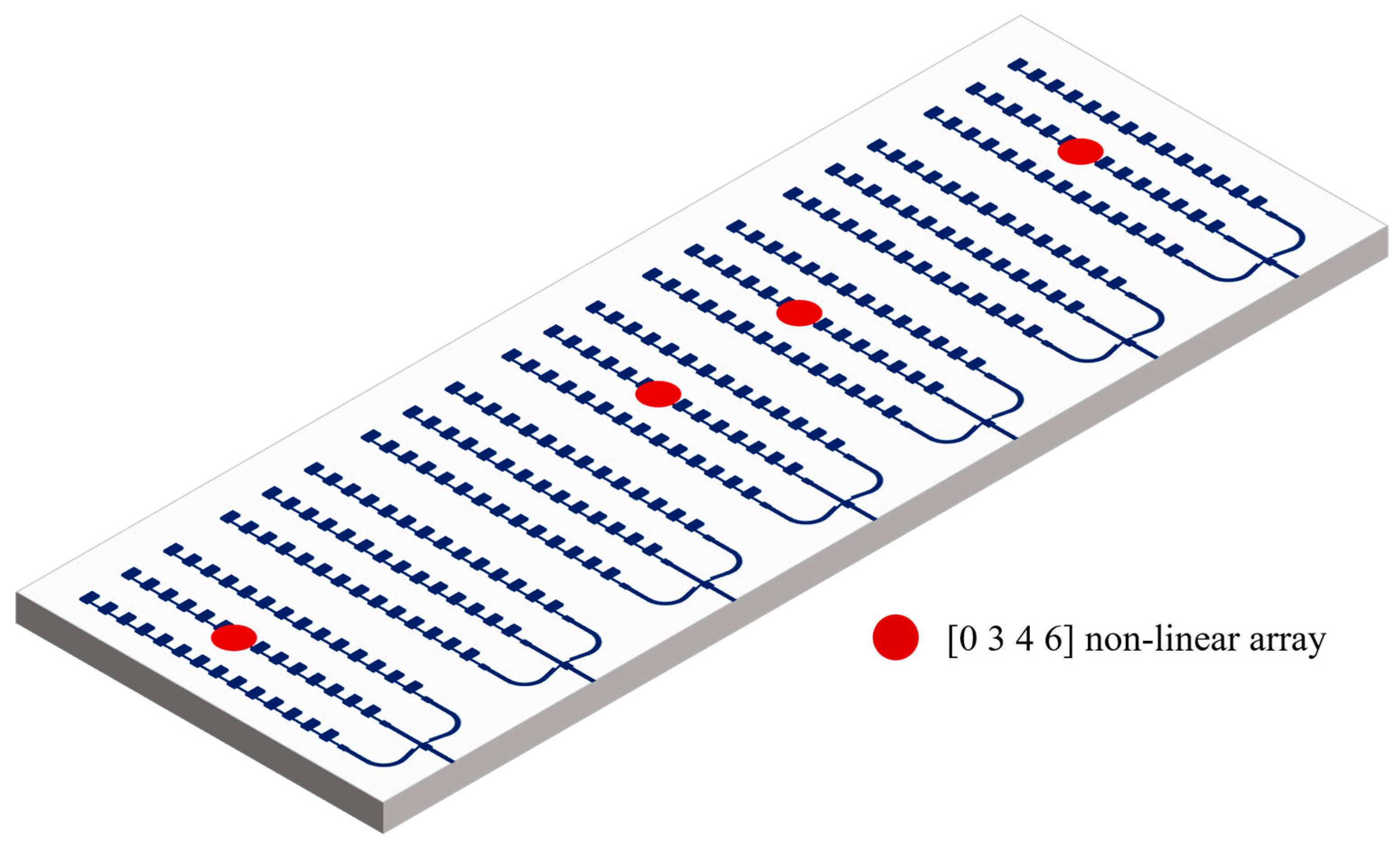
2.4. SIMO Antenna Layout Design

The radar’s field of view (FOV) θmax = arcsin(λ/2d) and angular resolution Δθ = λ/Dcos(θ) depend on the antenna spacing d and the total array length D. To facilitate clearance coverage and radar miniaturization, an FOV range of ±15° with an antenna spacing of 7.5 mm is an optimal configuration. Because of the weak SNR caused by the small-RCS blade oblique incidence from more than 70 m, blade clearance detection requires a high-Pt radar configuration rather than MIMO with a higher azimuth resolution. Therefore, combining three transmitting channels into one, namely SIMO configuration, is a good choice to acquire high Pt. To compensate for the lower angular resolution caused by fewer antenna channels, as shown in Figure 4, the linear array antenna can be altered to a [0 3 4 6] non-linear array to expand the total array length D, and the rest of the antennas are grounded. Figure 5 describes the normalized directional diagram of the antenna beam synthesis for linear and [0 3 4 6] non-linear arrays at the same spacing d. In the form of a non-uniform array layout, the receiving antenna aperture of the radar is increased, and the 3 dB beam width is improved from 4.7° to 3°, indicating that the angular resolution of the radar has been improved by 1.7°.

3. Antenna Design and Experimental Test

3.1. Antenna Design and Structure

Due to the trend of radar miniaturization and high integration, microstrip array antenna is the preferred choice for mmWave radar antenna [20]. This paper designs a pair of tangential circularly polarized antenna. Figure 6 demonstrate the stack structure and linear array of the proposed antenna. The antennas are simulated with CST Studio Suite 2019, a three-dimension electromagnetic simulation software. The linear antenna array includes 14 radiating elements fabricated on a substrate made of 3003 Roger material, which is 0.127 mm thick and has a permittivity and a loss tangent of 3 and 0.005, respectively. By adjusting the feed position and cutting angle, the amplitude ratio of the orthogonal electric field is controlled until two orthogonal modes with equal amplitude are excited. Among them, the length and width of the circularly polarized patch unit meet p = W∙L, q = W/L, and the relevant parameters of the final circularly polarized antenna unit are L = 1.07 mm, m = 0.04 mm, and W = 1.06 mm. The length of the circularly polarized patch unit is about half of the waveguide wavelength, and to ensure the same radiation of each unit, the spacing between the circularly polarized patch units is generally about one wavelength. Finally, after optimization simulation, the specific parameters are determined as follows: d = 2.62 mm, L = 1.12 mm, h=0.127 mm, Lmatch = 0.9 mm, m = 0.03 mm, W = 1.06 mm, and Wmatch = 0.39 mm.
In order to ensure that most of the transmitted electromagnetic waves are received back to the radar after scattering by the target, the beam width of the receiving antenna array is generally wider than that of the transmitting antenna array. This is reflected in the fact that the number of cells of the transmitting antenna is more than that of the receiving antenna [20]. By cascading the designed circularly polarized line array and the transmitting and receiving power splitter together, fine-tuning and optimization can obtain the transmitting 8 × 14 and receiving 3 × 14 circularly polarized surface array, as shown in Figure 7a,b.

3.2. The Experimental Test of Proposed Antenna

According to the antenna simulation model in Section 3.1, the fabricated physical diagrams of the circularly polarized transmitting and receiving antennas are shown in Figure 8, with dimensions of 43 × 18 mm2 (11.4 λ₀ × 4.8 λ₀) and 43 × 6 mm2 (11.4 λ₀ × 1.6 λ₀), respectively. Figure 9a,b present the simulated and measured radiation patterns of the circularly polarized transmitting and receiving antenna arrays. The peak gain of the measured circularly polarized transmitting antenna array is 21.4 dBi, with a sidelobe level of approximately −18.3 dB. The beam widths of the y’o’z’ and x’o’y’ planes are 11° and 6°, respectively. For the circularly polarized receiving antenna array, the peak gain is 18.4 dBi, with sidelobe levels lower than −20.0 dB. The beam widths of the y’o’z’ and x’o’y’ planes are 30° and 6°, respectively. Despite the inherent deflection angle of the antenna’s main lobe, the mechanical down-dip angle of the radar can effectively eliminate any beam shift in the antenna.
The simulated and measured bandwidths of the circularly polarized transmitting and receiving antennas are illustrated in Figure 10. The simulated and measured S-parameter results are shown in Figure 10a. The measured impedance bandwidths of the circularly polarized transmitting and receiving antennas cover 76–81 GHz, exceeding the 5 GHz bandwidth. In Figure 10b, the measured axial ratio bandwidths of the antennas are 78.5–80.3 GHz and 78–81 GHz, respectively. Within this frequency range, the circularly polarized antenna array exhibits good characteristics of circularly polarization for both transmission and reception.

4. RF Waveform Configuration

The chirp signal duration consists of 128 linear frequency-modulated chirps, each of which can mainly be characterized by a 240 us chirp cycle time and bandwidth B of 1.024 GHz. The frequency of the signal varies over time between the minimum frequency fmin and the maximum frequency fmax, as shown in Figure 11. The configuration of the RF chirp and frame affects the performance of the radar [21], and the RF waveform configuration needs to consider the following factors. First, based on the farthest detection distance and the chip sampling frequency limit formula Rmax = IFmaxC/2S, it can be determined that the maximum FMCW slope does not exceed 10 MHz/us. The range resolution of radar ΔR = C/2B means ΔR only depends on the frequency modulation bandwidth B of the transmitted waveform, and the frequency modulation bandwidth can be determined to be 1.024 GHz according to the requirements of range resolution. Second, the maximum speed Vmax = λ/4Tc is related to the chirp period. According to the requirements of the speed range and considering that the chirp period also needs to meet the conditions of data sampling, transmission time, and fumeless ranging, the final chirp period is determined to be 240 us. At the same time, the speed resolution only depends on the effective transmission period of the frame, according to the speed resolution ΔV = λ/2NTc, the frame period is finally determined to be 35 ms. A detailed listing of AWR2243’s RF bandwidth, chirp slope, sampling rate, and ADC sampling performance is shown in the Table 3 below.

5. Radar Experiments

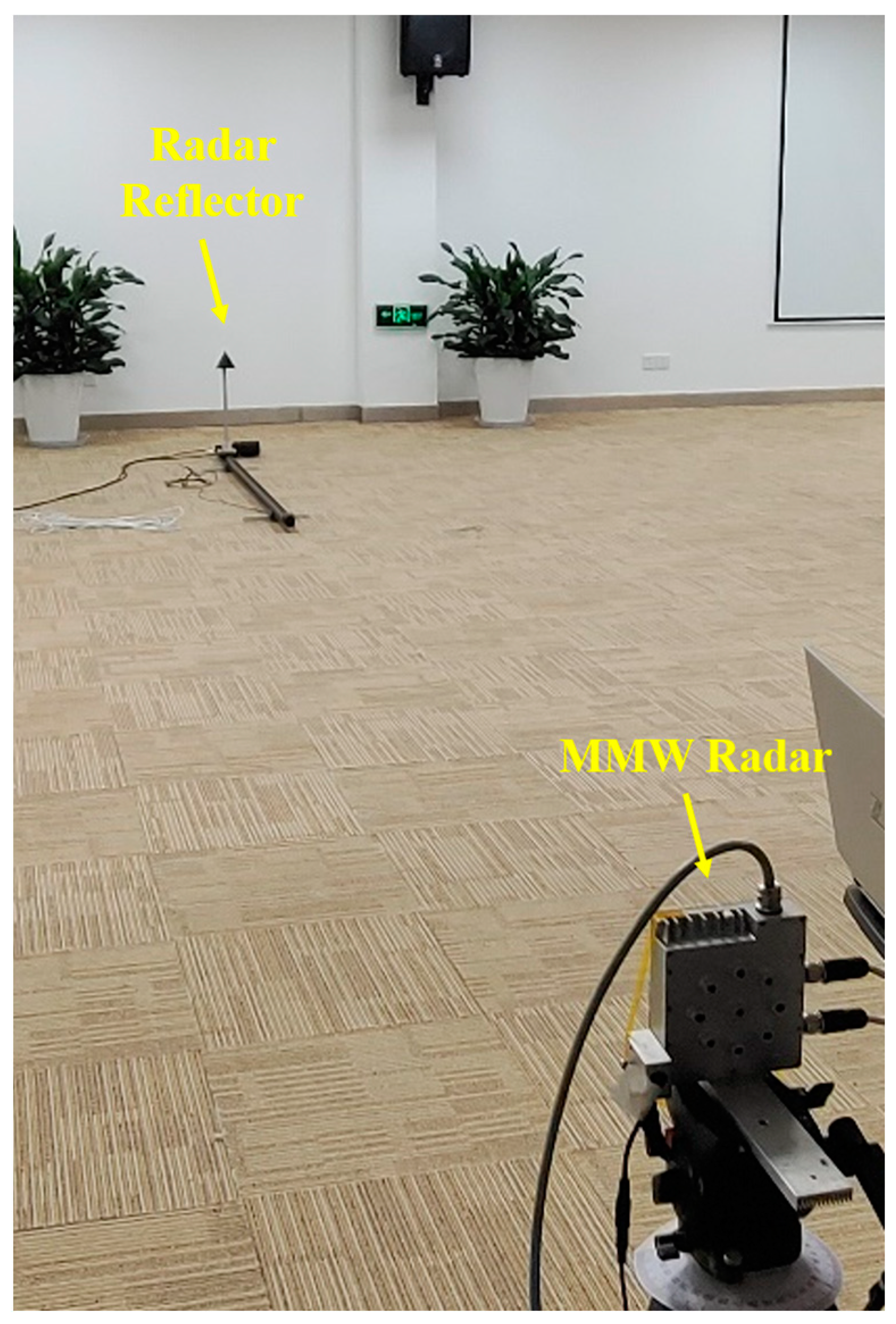
5.1. Radar Performance Test

In Figure 12, the circularly polarized radar used to monitor wind turbine blades is composed of a structural shell, a RF board, and a baseband signal processing board. The latter two boards are connected by a flexible wire.
Before the radar was installed on the wind turbine, radar performance experiment is implemented to evaluate the measurement accuracy of the proposed mmWave radar. As shown in Figure 13, the radar is set up on the ground through a tripod, and the 1.2 m guide rail is placed longitudinally at the mechanical zero point of the radar coordinate system. The radar reflector moves longitudinally and reciprocally on the guide rail. By measuring the distance, velocity angle of the target moving on the guide rail, the three-dimensional information of the target measured by radar is compared and calibrated.
Figure 14 shows the test results. The nearest and the farthest end of the guide rail is 2.9 m and 5.1 m with a measured distance of 2.92 m and 5.11 m, the corresponding speeds are 2.75 m/s and −2.5 m/s in forward and reverse direction, respectively. Angle is also calibrated to 0°, the measured maximum and minimum angle are 0.125° and 0.125°, with a tolerance less than 0.125°. The results show that the radar measured distance, velocity, and angle distribution is consistent with the actual movement of the target on the rail, indicating that the radar achieves a high degree of accuracy in terms of performance and can be used for field clearance detection.

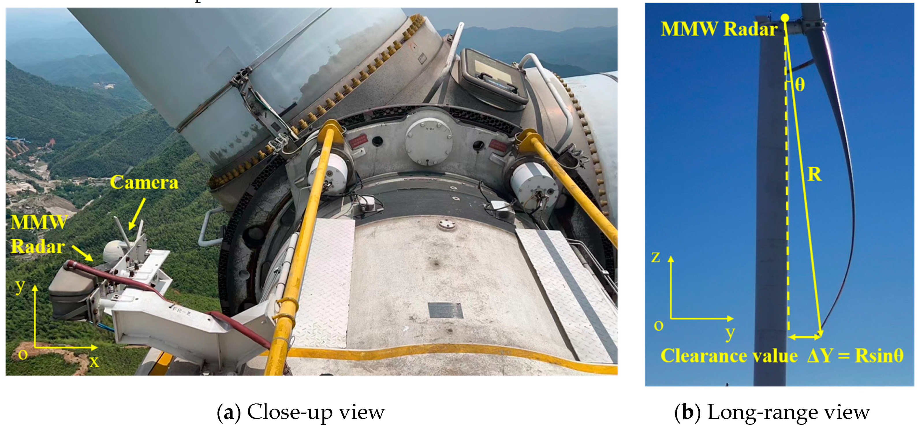
5.2. Radar Experiments on a Practical Wind Turbine

Practical experiments are performed in a wind turbine using an mmWave radar sensor to verify the proposed method and to analyze the performance of the blade tip clearance detection. The circularly polarized radar is installed on the top of the wind turbine through a bracket, as shown in Figure 15a. The radar is initially vertically oriented towards the ground and then rotated at a specific angle towards the blade tip, such that the radar is pointed toward the center of the clearance area.
The mmWave FMCW radar uses high frequency chirp signals to scan the scene. As the chirp signal encounters a blade tip target, the signal is reflected and picked up by the receiving antenna. The RF-integrated chip in the antenna extracts the echo, which contains valuable target information. The W-band RF signal obtained is then fed into a mixer to obtain the intermediate frequency (IF) signal, which is further processed for signal analysis. The signal processing techniques utilize the analog-to-digital converter (ADC) data to generate range-Doppler (RD) maps by executing a 2D-FFT in every discrete frame to calculate the distance R and speed V of the target. Subsequently, the constant false alarm rate algorithm (CFAR) computes the noise level in the RD matrix and extracts the blade tip signal. Afterward, we use the direction of arrival (DOA) algorithm to determine the income wave direction θ. Ultimately, the target’s three-dimensional information (R,V,θ) is translated into the clearance value by the formula clearance value ΔY = Rsinθ shown in Figure 15b. To analyze the turbine’s performance, the range-Doppler spectrum after CFAR of the radar is extracted and displayed in Figure 16. When the turbine is functioning properly, the blade tip bends inward, and both the radar root and tip area are visible. At a distance of 73.4 m, the blade tip moves at around 1.8 m per second. The background and signal intensity are 27 dB and 34 dB, respectively, resulting in an SNR of 7 dB.
The radar system used in the wind turbine can operate continuously and capture the blade tip target to record the clearance curve and rotor speed curve accurately. The clearance value is calculated by filtering out the tip point of the blade, and the real-time rotational speed of the turbine is calculated based on the time difference between two adjacent clearance data. The collected data, presented in Figure 17, displays the blade clearance values and the wind turbine rotor speed curves of the target detection radar, represented by black and red lines, respectively. During testing, the wind turbine operates at a speed range of 6 to 12 rounds per minute (RPM), with a clearance range of 6 to 12 m. As clearance measurement is a relatively new concept with limited reference standards, it is imperative to ascertain the reliability of the clearance value. This paper proposes two ways of checking the accuracy of the results. In the first place, to calibrate the maximum and minimum clearance value accurately, manual measurement can be obtained at these limit positions. Table 4 provides the calibration values for maximum and minimum rotor speeds. At a minimum wind turbine rotor speed of 6 RPM, the manual calibration value is 12 m, and the clearance value measured by radar is 11.534 m. Similarly, at a maximum rotor speed of 12 RPM, the manual calibration value is 5.5 m, and the clearance value measured by radar is 5.85 m. The deviation of ±0.5 m between the two measurement methods demonstrates the high accuracy of the proposed scheme at 0.5 m. Secondly, the inverse relationship between rotor speed and clearance also reflects the accuracy of the results. This is because when the blade rotor speed is higher, there is a greater wind speed and pressure on the wind blade, which results in a smaller blade-tip clearance to the tower. Conversely, lower wind rotor speeds result in larger tip clearance to the tower.
Through careful analysis and comparison of the data, it is evident that with increased wind speed and rotor speed, the blades bend inward and the clearance value decreases. The curve of the clearance value and the wind speed clearly shows the inverse trend. Nevertheless, there are certain abrupt points in the measured clearance value, and these can be attributed to inconsistencies in the degree of deformation of the three blades and sudden changes in instantaneous wind speed. Notably, the results of the mmWave circularly polarized radar test, conducted under various weather conditions including sunny, cloudy, overcast, light rain, and thunderstorm, demonstrate its accurate detection of target objects and provision of reliable data. These findings confirm the high interference resistance and adaptability to different weather conditions of the proposed mmWave circularly polarized radar.
Table 5 compares the proposed mmWave radar with other works, highlighting a longer detection range and the all-weather operation. In contrast to the laser method in [1], the radar in this paper is installed top of the tower, with a longer detection distance and a wider coverage area. In the literature [2], the ground camera sensor is placed 30–40 m away from the wind turbine, which cannot effectively measure the blade-tip clearance under different yaw azimuth. In reference [3], mmWave radars are positioned in the middle of the tower, with a detection range of 5 to 20 m. Furthermore, the installation of up to eight mmWave radars is expensive. In particular, this paper for the first time presents the experiments in various weather conditions including sunny, cloudy, overcast, light rain, and thunderstorm, which are not mentioned in the literature [1,2,3].

6. Conclusions

This paper presents a 79 GHz mmWave radar system installed on the top of the tower with a pair of circularly polarized antenna to monitor the distance between wind turbine blades and the tower. To mitigate the low channel SNR caused by a small-RCS blade obliquely incident from more than 70 m, high-gain antennas and SIMO radar configurations are designed to increase the Pt of the link. In addition, a pair of circularly polarized antenna is used to reduce the high level of weather interference from an unfriendly environment. In this paper, the radar architecture design is introduced, and the circularly polarized antenna is simulated and measured. Finally, the experimental results demonstrate the performance of the circularly polarized mmWave radar in various weather conditions, including sunny, cloudy, overcast, light rain, and thundershower, proving the feasibility of the circularly polarized mmWave radar in detecting blade clearance with good performance.

Author Contributions

Conceptualization, J.C., B.G., Y.J. and Y.L.; validation, J.C., Y.J., and Z.B.; writing—original draft preparation, J.C.; writing—review and editing, Y.L.; project administration, Y.L., L.W., S.W. and R.W. funding acquisition, G.Y. All authors have read and agreed to the published version of the manuscript.

Funding

This work is supported by Suzhou Dufeng Technology Co., Ltd. under Grant No. D71-0107-19-115.

Data Availability Statement

The data presented in this study are private, and it comes from the school of Communication and Information Engineering, Shanghai University, and Suzhou Dufeng Technology Co. Ltd.

Conflicts of Interest

The Author Bin Guo was employed by the CGN Digital Technology Co., Ltd. Authors Lijun Wang, Siye Wang and Guangli Yang was employed by the Suzhou Dufeng Technology Co., Ltd. The remaining authors declare that the research was conducted in the absence of any commercial or financial relationships that could be construed as a potential conflict of interest. The funders had no role in the design of the study; in the collection, analyses, or interpretation of data; in the writing of the manuscript; or in the decision to publish the results.

References

  1. Lee, J.R.; Kim, H.C. Feasibility of in situ blade deflection monitoring of a wind turbine using a laser displacement sensor within the tower. Smart Mater. Struct. 2012, 22, 027002. [Google Scholar] [CrossRef]
  2. Guan, B.; Su, Z.; Yu, Q.; Li, Z.; Feng, W.; Yang, D.; Zhang, D. Monitoring the blades of a wind turbine by using videogrammetry. Opt. Lasers Eng. 2022, 152, 106901. [Google Scholar] [CrossRef]
  3. Zhang, L.; Wei, J. Measurement and control method of clearance between wind turbine tower and blade-tip based on millimeter-wave radar sensor. Mech. Syst. Signal Process. 2021, 149, 107319. [Google Scholar] [CrossRef]
  4. Banerjee, U.; Karmakar, A.; Saha, A. A review on circularly polarized antennas, trends, and advances. Int. J. Microw. Wirel. Technol. 2020, 12, 922–943. [Google Scholar] [CrossRef]
  5. Schneider, D.A.; Rosch, M.; Tessmann, A.; Zwick, T. A LowLoss W-Band Frequency-Scanning Antenna for Wideband Multichannel Radar Applications. IEEE Antennas Wirel. Propag. Lett. 2019, 18, 806–810. [Google Scholar] [CrossRef]
  6. Asaadi, M.; Sebak, A. High-Gain Low-Profile Circularly Polarized Slotted SIW Cavity Antenna for MMW Applications. IEEE Antennas Wirel. Propag. Lett. 2017, 16, 752–755. [Google Scholar]
  7. McFee, R.; Maher, T. Effect of surface reflections on rain cancellation of circularly polarized radars. IRE Trans. Antennas Propag. 1959, 7, 199–201. [Google Scholar] [CrossRef]
  8. Semplak, R.A. Simultaneous measurements of depolarization by rain using linear and circular polarizations at 18 Ghz. Bell Syst. Tech. J. 1974, 53, 400–404. [Google Scholar] [CrossRef]
  9. Zhu, Q.; Ng, K.B.; Chan, C.H. Printed circularly polarized spiral antenna array for miilimeter wave applications. IEEE Trans. Antennas Propag. 2017, 65, 636–642. [Google Scholar] [CrossRef]
  10. Zhang, J.; Huang, Y.; Li, Z. Analysis of polarization matching and transmitting/receiving pattern reciprocity of antenna. In Proceedings of the 2014 3rd Asia-Pacific Conference on Antennas and Propagation, Harbin, China, 26–29 July 2014; pp. 248–251. [Google Scholar]
  11. Gyasi, K.O.; Wen, G.; Inserra, D.; Huang, Y.; Li, J.; Ampoma, A.E. A compact broadband cross-shaped circularly polarized planar monopole antenna with a ground plane extension. IEEE Antennas Wirel. Propag. Lett. 2018, 17, 335–338. [Google Scholar] [CrossRef]
  12. Tong, C.; Kremer, H.I.; Yang, N.; Leung, K.W. Compact wideband ircularly polarized dielectric resonator antenna with dielectric vias. IEEE Antennas Wirel. Propag. Lett. 2022, 21, 1100–1104. [Google Scholar] [CrossRef]
  13. Xu, Y.; Zhu, L.; Liu, N. Design approach for a dual-band circularly polarized slot antenna with flexible frequency ratio and similar in-band gain. IEEE Antennas Wirel. Propag. Lett. 2022, 21, 1037–1041. [Google Scholar] [CrossRef]
  14. Wu, J.; Yang, W.; Gu, L.; Xue, Q.; Che, W. Low-profile widebanddual-circularly polarized metasurface antenna based on traveling-wave sequential feeding mechanism. IEEE Antennas Wirel. Propag. Lett. 2022, 21, 1085–1089. [Google Scholar] [CrossRef]
  15. Dey, K.C.; Mishra, A.; Chowdhury, M. Potential of intelligent transportation systems in mitigating adverse weather impacts on road mobility: A review. IEEE Trans. Intell. Transp. Syst. 2015, 16, 1107–1119. [Google Scholar] [CrossRef]
  16. Skolnik, M.I. Introduction to Radar Systems, 2nd ed.; McGraw-Hill, Inc.: New York, NY, USA, 1981. [Google Scholar]
  17. Chen, C.C. Attenuation of Electromagnetic Radiation by Haze, Fog, Clouds, and Rain; The Rand Corporation: Santa Monica, CA, USA, 1975. [Google Scholar]
  18. Texas Instrument xWR2243 Evaluation Module (xWR2243BOOST). Available online: https://www.ti.com/tool/AWR2243BOOST (accessed on 7 December 2023).
  19. Levanon, N. Radar Principles, 1st ed.; John Wiley and Sons: New York, NY, USA, 1988. [Google Scholar]
  20. Wong, K.L.; Ke, S.Y. Cylindrical-rectangular Microstrip Patch Antenna for Circular Polarization. IEEE Trans. Antennas Propag. 1993, 41, 246–249. [Google Scholar] [CrossRef]
  21. The Fundamentals of MMW Radar Sensors. Available online: https://www.ti.com/lit/wp/spyy005a/spyy005a.pdf (accessed on 7 December 2023).
Figure 1. Wind turbine blade bending.
Electronics 13 00462 g001
Figure 2. Radar installation diagram.
Electronics 13 00462 g002
Figure 3. System block diagram.
Electronics 13 00462 g003
Figure 4. [0 3 4 6] Non-linear antenna array.
Electronics 13 00462 g004
Figure 5. Schematic diagram of the normalized direction of the receiving array.
Electronics 13 00462 g005
Figure 6. Antenna line array configuration.
Electronics 13 00462 g006
Figure 7. Configuration of (a) transmitting and (b) receiving antenna.
Electronics 13 00462 g007
Figure 8. Antennas physical diagrams.
Electronics 13 00462 g008
Figure 9. Simulated and measured radiation patterns.
Electronics 13 00462 g009
Figure 10. Simulated and measured impedance and axis ratio bandwidth.
Electronics 13 00462 g010
Figure 11. Chirp and frame geometry of AWR2243.
Electronics 13 00462 g011
Figure 12. Radar system physical picture.
Electronics 13 00462 g012
Figure 13. Photograph of mmWave radar performance test.
Electronics 13 00462 g013
Figure 14. Measurement data of millimeter wave radar.
Electronics 13 00462 g014
Figure 15. Radar installation position.
Electronics 13 00462 g015
Figure 16. Range-Doppler spectrum.
Electronics 13 00462 g016
Figure 17. Test results under different weather conditions.
Electronics 13 00462 g017aElectronics 13 00462 g017b
Table 1. Scenario parameters.
IDIndex NameValue
1Maximum detection range Rmax150 m
2Range resolution ΔR0.15 m
3Maximum speed range Vmax±4 m/s
4Velocity resolution ΔR0.0625 m/s
5Field Angle range θmax±15°
6Angular resolution Δθ
Table 2. Parameter comparison of millimeter-wave radars.
IDIndex NameK-Band RadarW-Band Radar
1Frequency range24~24.25 GHz76~81 GHz
2Bandwidth250 MHz5 GHz
3Range resolutionMinimum 60 cmMinimum 3.75 cm
4Velocity resolutionLowThree times the former
5Antenna sizeLargeA third of the former
Table 3. RF waveform configuration.
IDIndex NameValue
1Numbers of ADC samples N1024
2Numbers of Doppler samples M128
3Chirp slope k10 MHz/μs
4Frequency modulation bandwidth B1.024 GHz
5Chirp period T c 240 μs
6Frame period T f 35 ms
Table 4. Comparison between the manual and radar measurements at minimum and maximum rotor speed.
Manual MeasurementRadar Measurement
Minimum rotor speed
(6 RPM)
12 m11.534 m
Maximum rotor speed
(12 RPM)
5.5 m5.85 m
Table 5. Performance comparison of other published literature.
IDMethodDetection RangeWeather
[1]one laser5 to 20 m
(middle of the tower to the blade tip)
N/A
[2]one camera30 to 40 m
(ground to the blade tip)
N/A
[3]eight 24 GHz mmWave radar5 to 20 m
(middle of the tower to the blade tip)
N/A
This workone 79 GHz mmWave radar70 to 80 m
(top of the tower to the blade tip)
sunny, cloudy, overcast, light rain, thunderstorm
Disclaimer/Publisher’s Note: The statements, opinions and data contained in all publications are solely those of the individual author(s) and contributor(s) and not of MDPI and/or the editor(s). MDPI and/or the editor(s) disclaim responsibility for any injury to people or property resulting from any ideas, methods, instructions or products referred to in the content.

