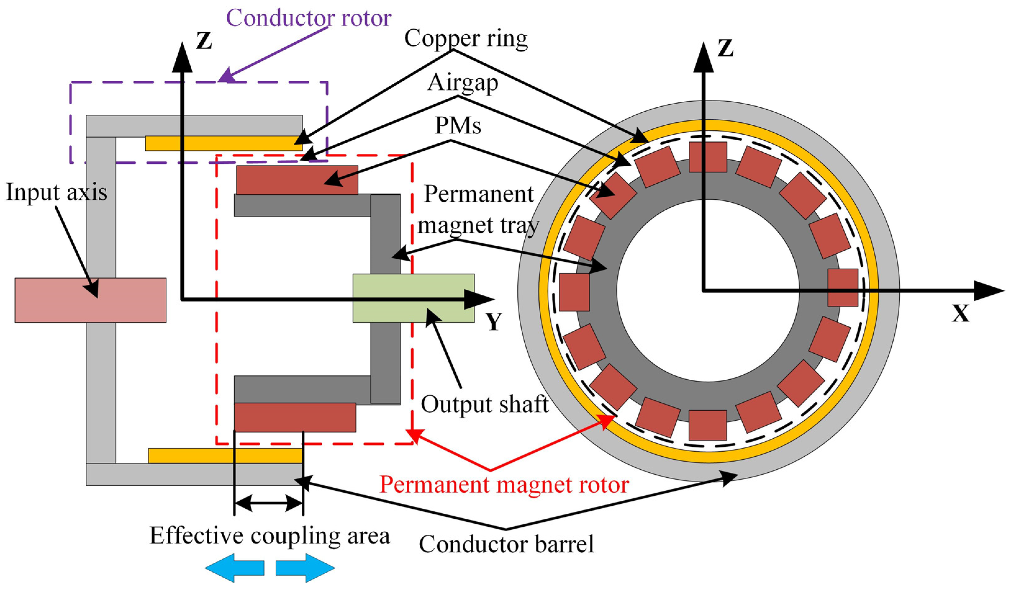
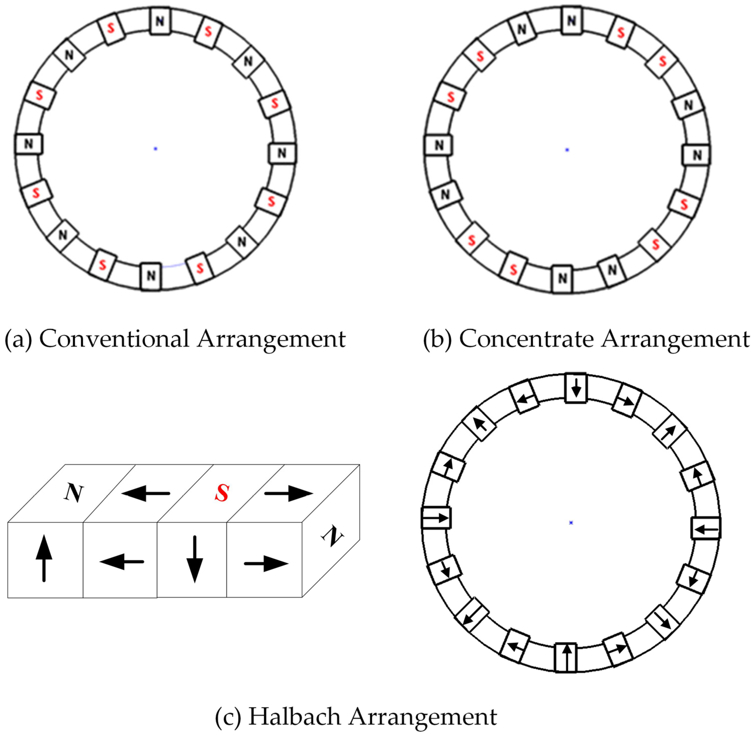
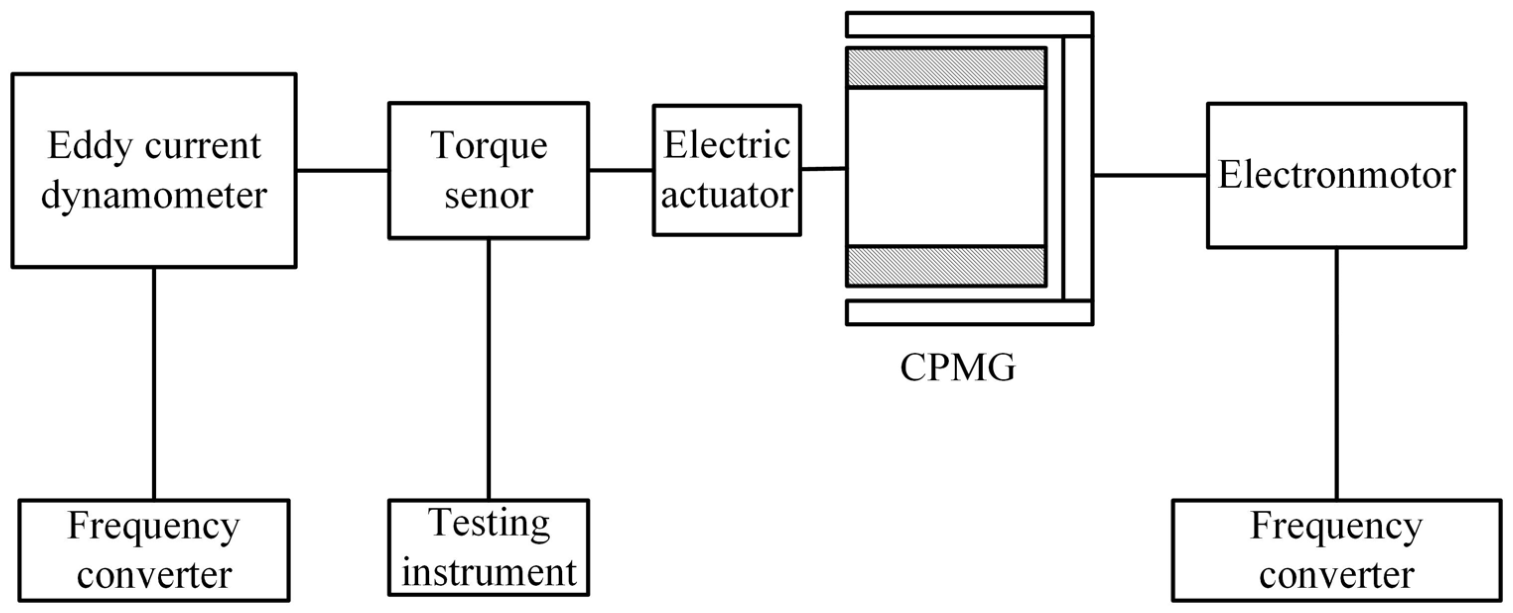
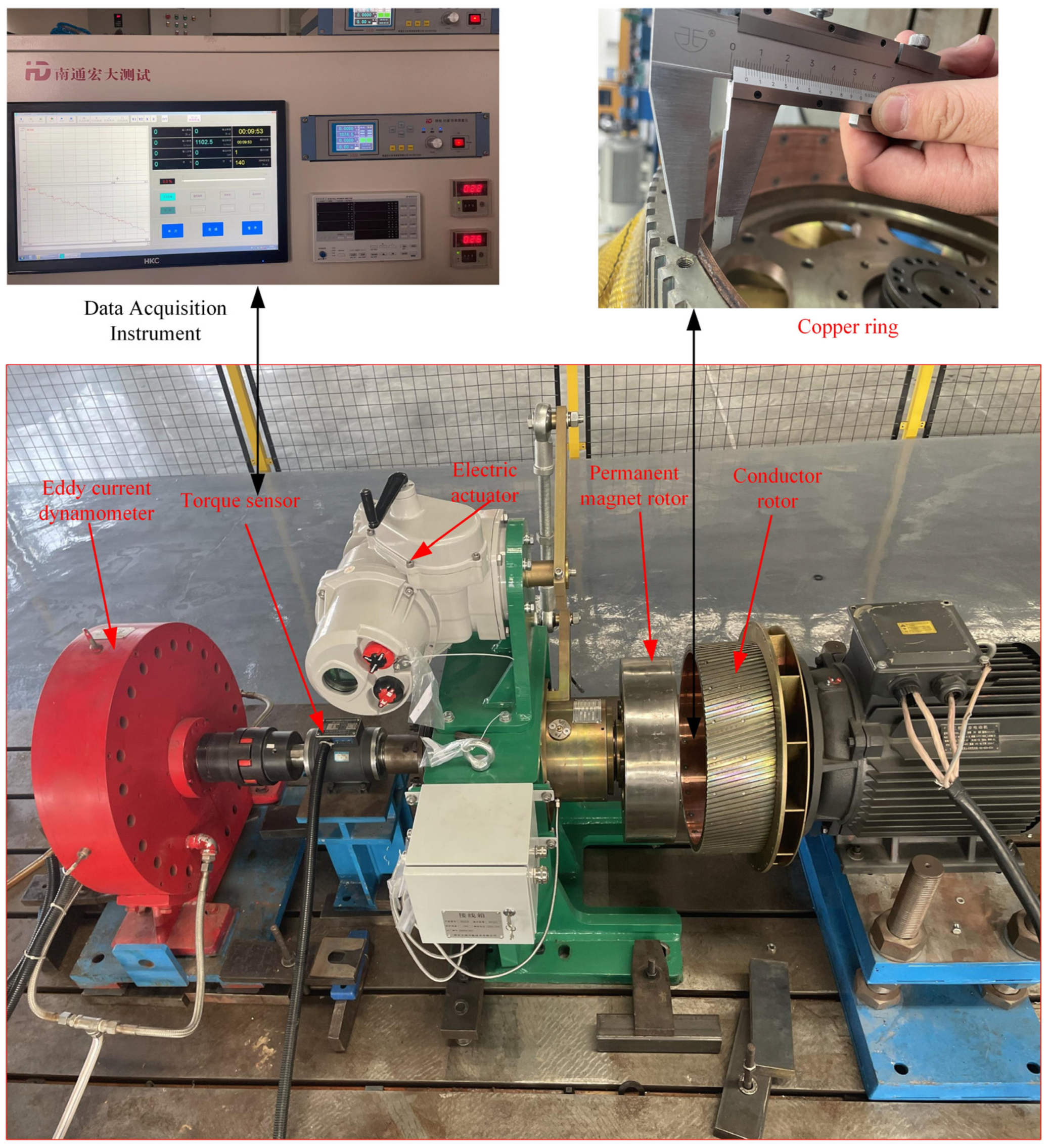
2.1. Cylindrical Permanent Magnet Governor with Halbach Magnet Array
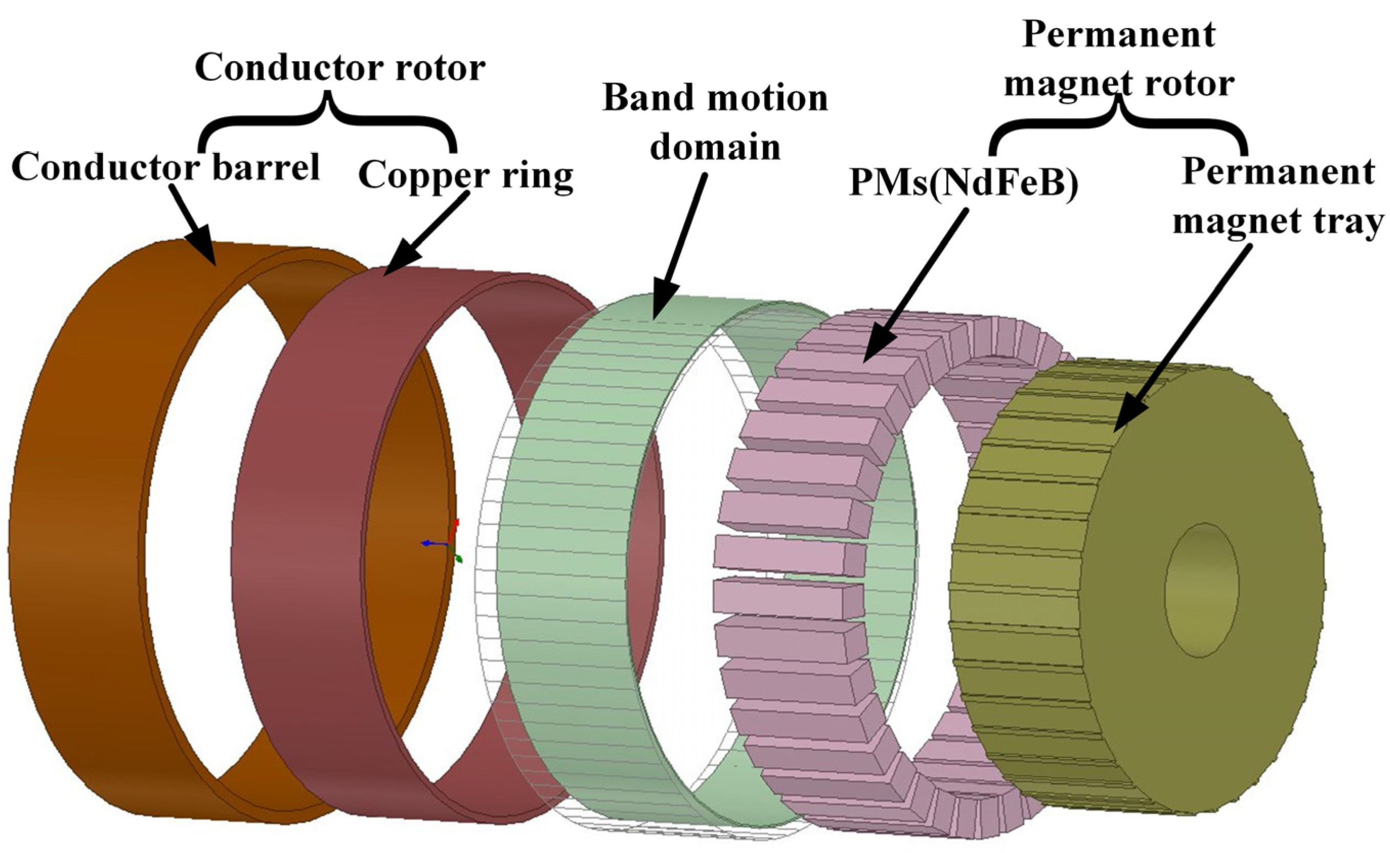
CPMG is composed of the conductor rotor, which is mainly composed of a conductor barrel, a copper ring and the permanent magnet rotor. The permanent magnet rotor contains a permanent magnet tray and PMs, where the PMs are embedded in the permanent magnet tray. As shown in
Figure 1, the conductor rotor is connected to the motor shaft, and the output axis is connected to the permanent magnet rotor. There is no contact between the conductor and the permanent magnet rotor, which allows a certain alignment error during installation.
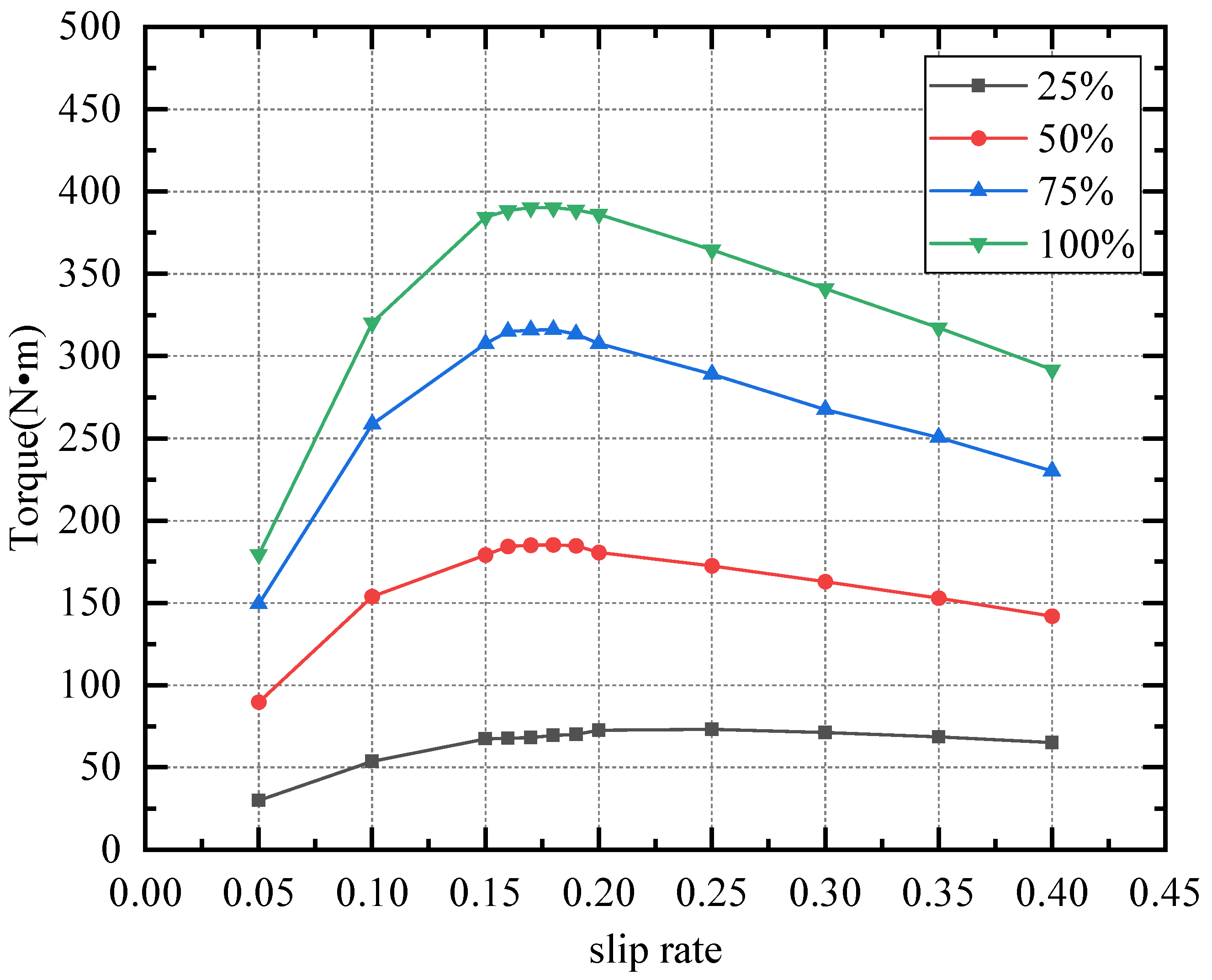
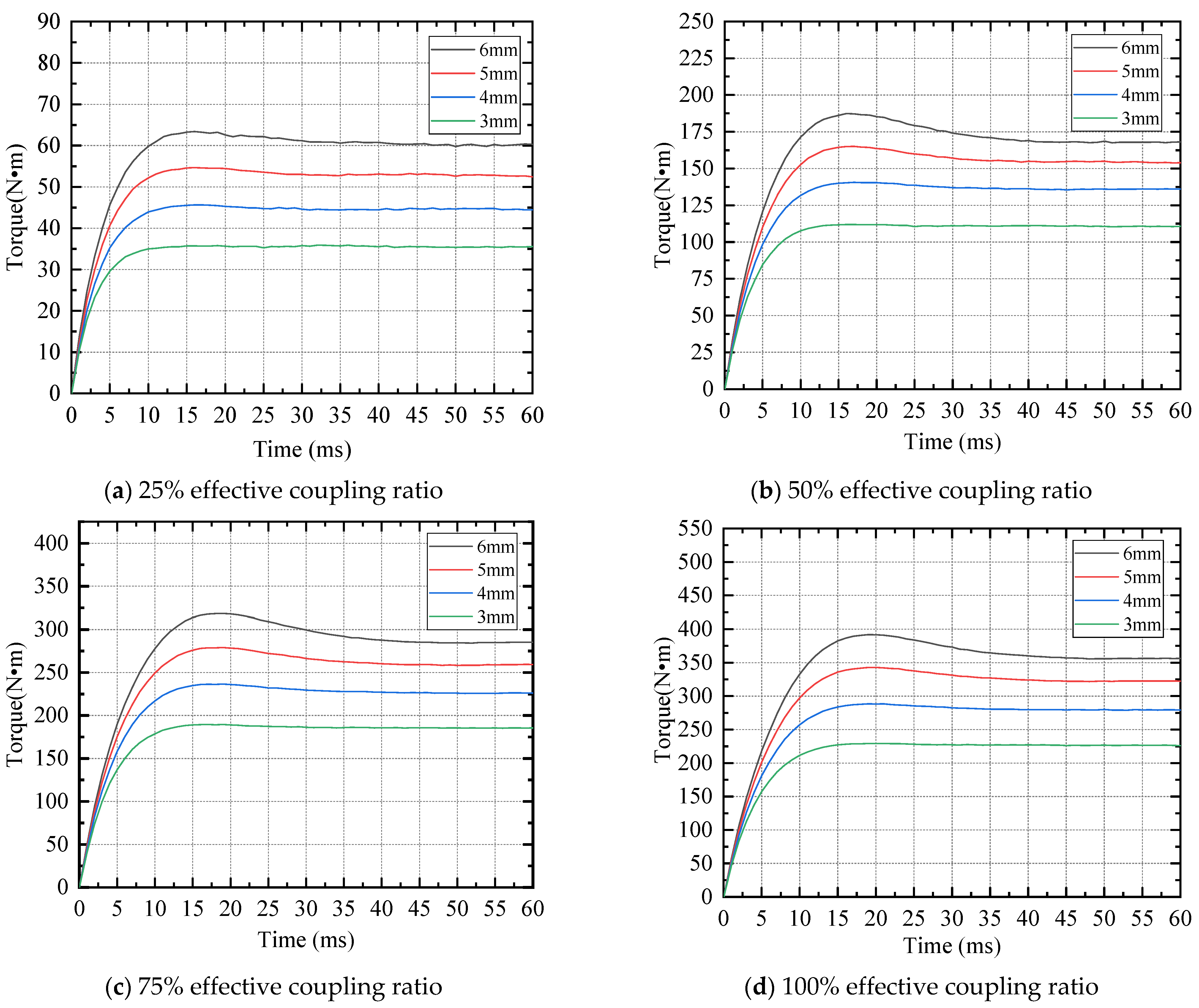
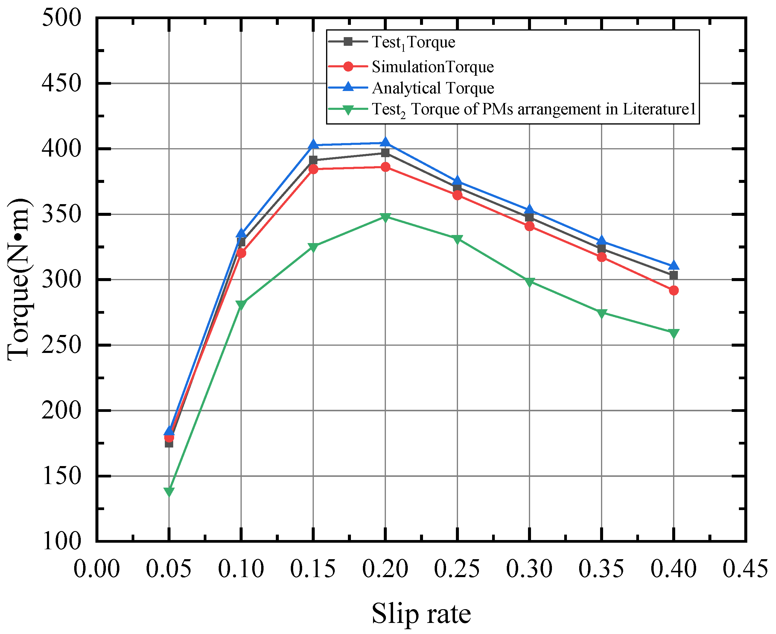
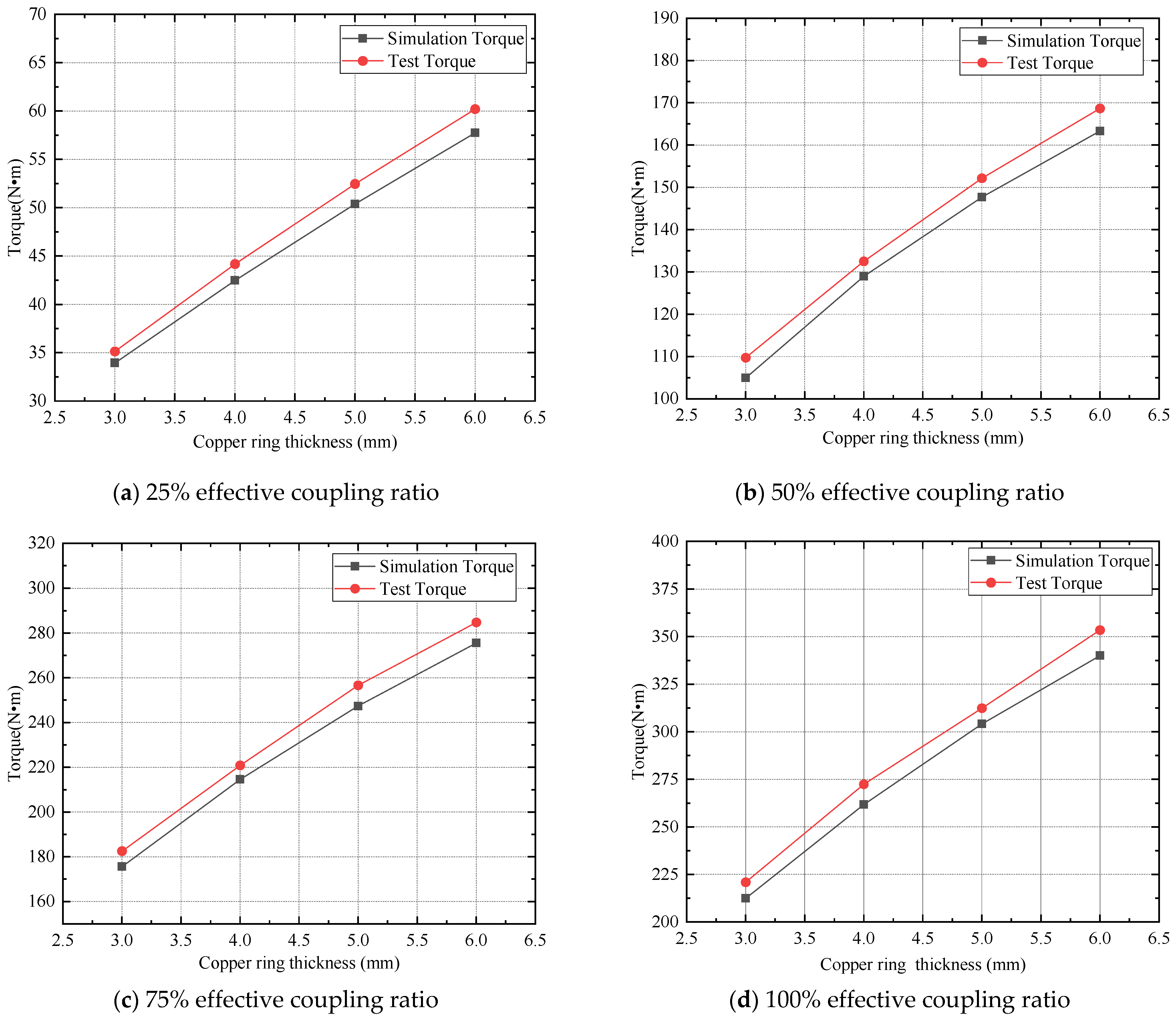
When the motor is in operation, the conductor barrel connected to the motor shaft is rotating, which cuts the magnetic field generated by the permanent magnet array. An induced current is generated in the copper ring. A Lorentz force is applied to the copper ring, which generates a torque to drive the permanent magnet array. There is always a rotation speed difference between the conductor and permanent magnet array in order to ensure the presence of output torque. The rotation speed of the output shaft and output torque can be adjusted by regulation of the effective coupling area between the conductor and the permanent magnet array.
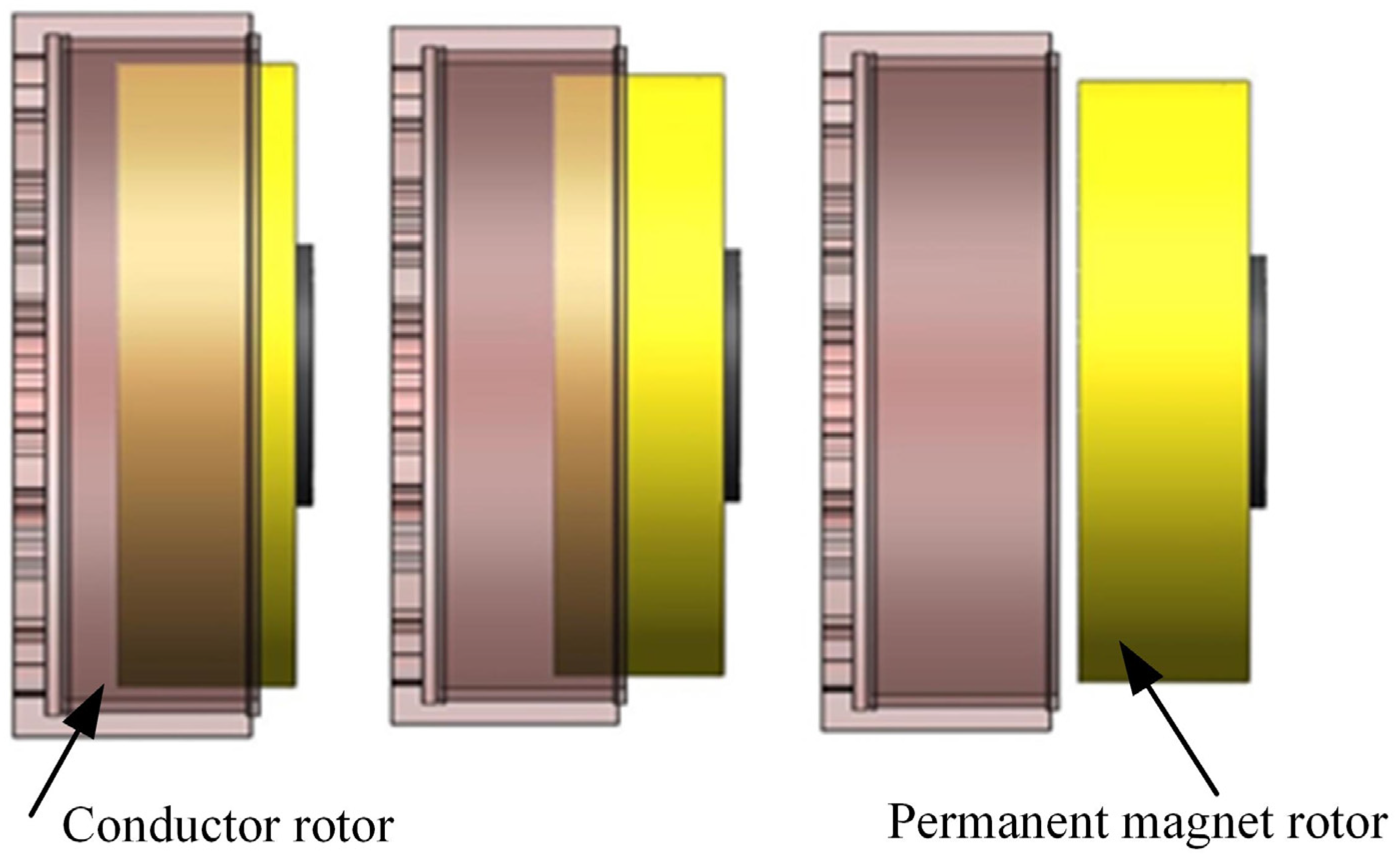
The schematic diagram of the specific speed regulation principle is shown in
Figure 2. The output torque and rotation speed can be tuned through the adjustment of the effective coupling ratio (the ratio of the actual coincidence area between the conductor and the permanent magnet to the full coincidence area). The maximum output torque can be realized when the permanent rotor is fully coupled to the rotor of conductors (100% effective coupling ratio).
2.2. Equivalent Magnetic Circuit of Halbach Permanent Magnet Cell and Simulation Model
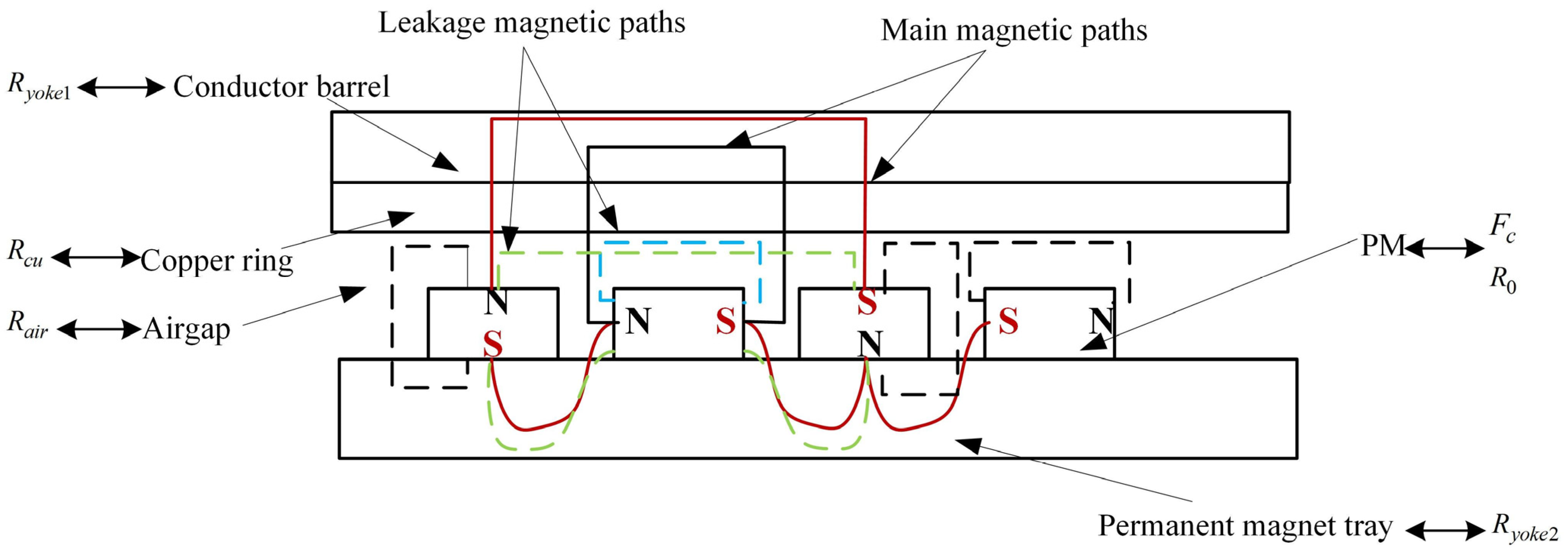
In order to simplify the process for analysis, the main components of CPMG were unfolded radially into a 2D model. The magnetic field distribution was assumed to be linear in CPMG without consideration of leakage. The equivalent model of a Halbach cell is shown in
Figure 3. The permanent magnet’s geometry was considered to be rectangular shaped, which can be equalized to the magnetomotive. The main flux paths (solid line) were where it passes through PMs, airgap, copper ring, conductor barrel and permanent magnet tray. The leakage flux paths (dashed line) were mainly generated between adjacent permanent magnets.
On the basic, before-mentioned Equivalent magnetic model of a Halbach permanent magnet cell analysis, the permanent magnet’s geometry is considered to be rectangular shaped, which is equalized to be magnetomotive. The Conductor barrel is regarded as
, the permanent magnet tray is regarded as
, the copper ring is regarded as
, and the space in between the adjacent permanent magnets is regarded as
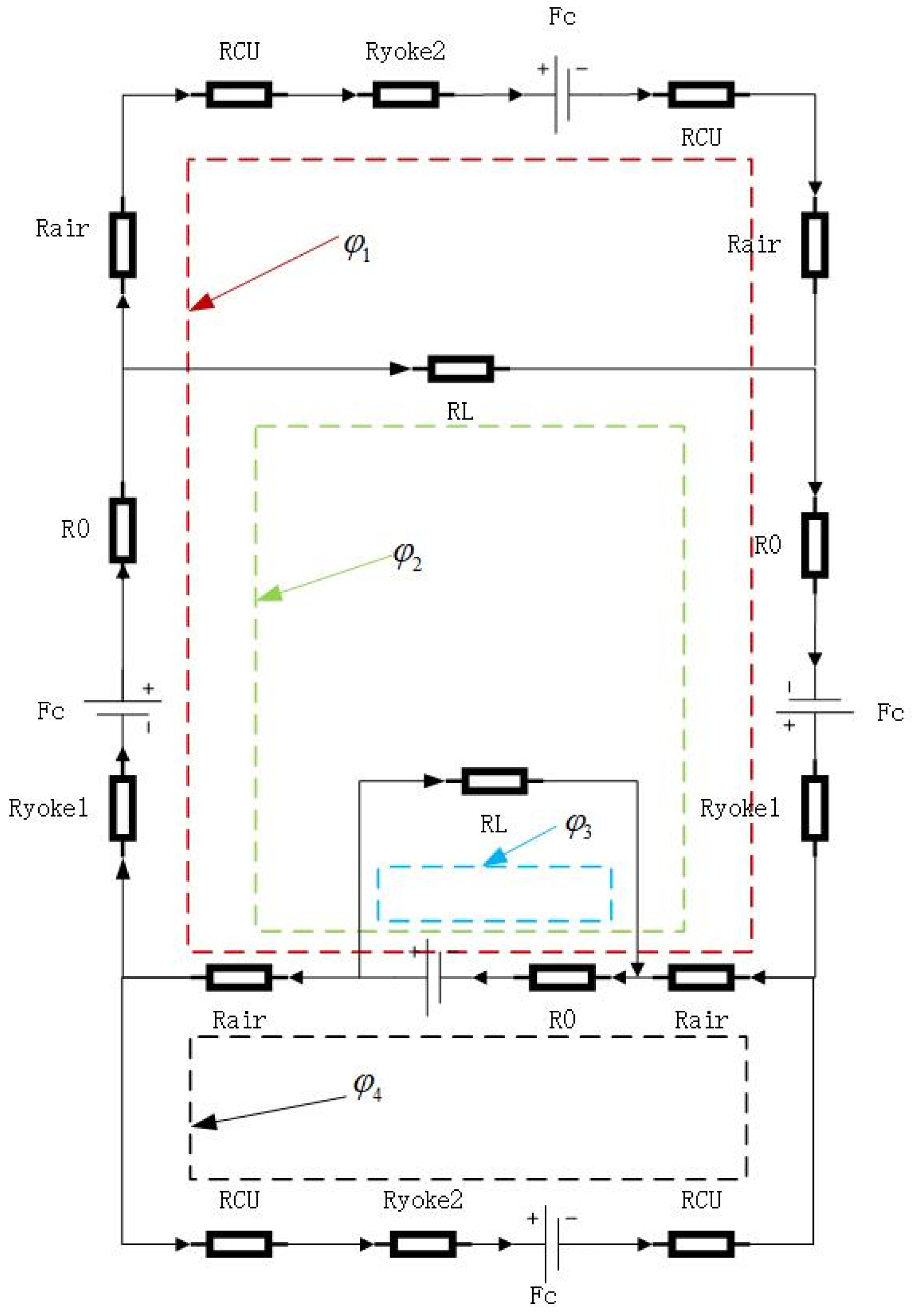
. Therefore, the magnetic reluctance circuit of the Halbach permanent magnet cell is presented in
Figure 4, where only a pair of Halbach array magnets is considered on account of the symmetry of the magnetic circuit.
According to the principles of equal magnetic circuits, a magnetic circuit was studied under a pair of magnetic poles, and a permanent magnet was regarded as the magnetomotive force
, in series with the internal reluctance
of the permanent magnet, to form the magnetomotive force source.
where
Hc is the coercive force of the permanent magnet, and
hmp is the magnetization direction length of the permanent magnet. When the permanent magnet governor is operating, the induced electromotive force in the copper ring during the cutting of the magnetic field generated by the permanent magnet array is created by the eddy current, which increases the armature magnetomotive force
Fa.
The magnetic reluctance in the circuit is calculated below:
where
L represents the length and
S represents the cross-section of the magnet circuit, and
represents the magnetic permeability.
According to the current KCL law, the magnetic circuit equations of the Halbach magnet cell are built as below:
In Equation (3), , , and represent the flux of air between the four magnets.
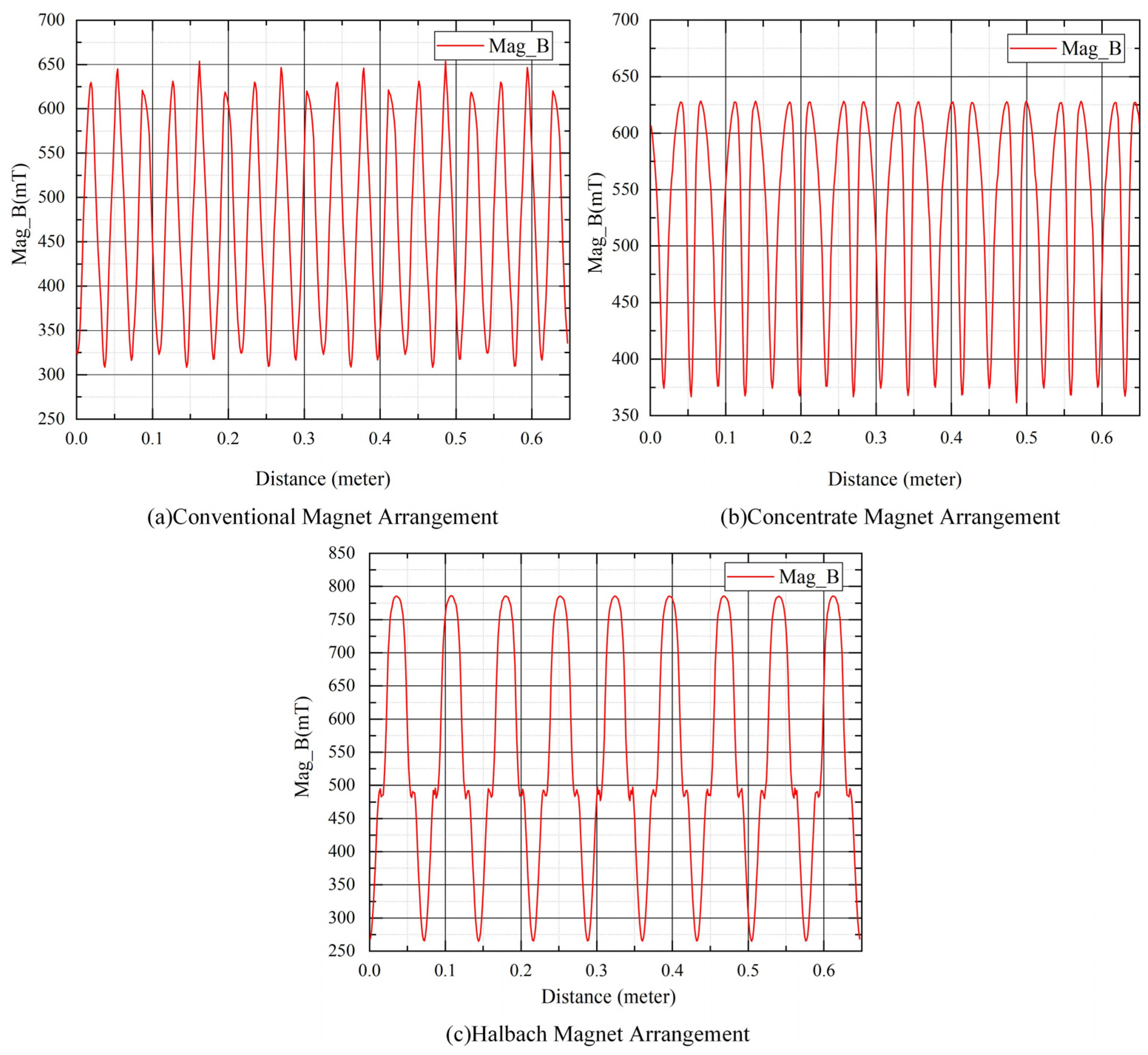
Magnetic induction strength in the air gap
where
is the average magnetic flux of the pair of polar poles and
is a cross-sectional area that corresponds with the air gap.
The average electromotive force is calculated as follows:
The induced current inhibits the penetration of magnetic fields in the ring of copper, and it only allows magnetic fields to penetrate at a specific depth, which is called the skin effect. Due to the skin effect, the inducing currents are concentrated at the surface of the copper ring. The current decays rapidly beyond the depth of penetration. The penetration is decreased with the rotation frequency. The penetration depth expression is as follows
In Equation (6), is a radial frequency, is copper conductivity, and represents the relative permeability of copper rings. In Equation (7), is the speed difference and is the number of pole pairs.
The induced eddy current region is generated by a single permanent magnet on the copper ring, which is equivalent to a circular region with a diameter of
d. Therefore, the reluctance of the ring of the eddy current is shown below:
The area of the eddy current region is as follows:
The instantaneous eddy current obtained from the above equation is:
The eddy current loss generated by the permanent magnet corresponding to the copper ring is
where
n is the number of permanent magnet blocks.
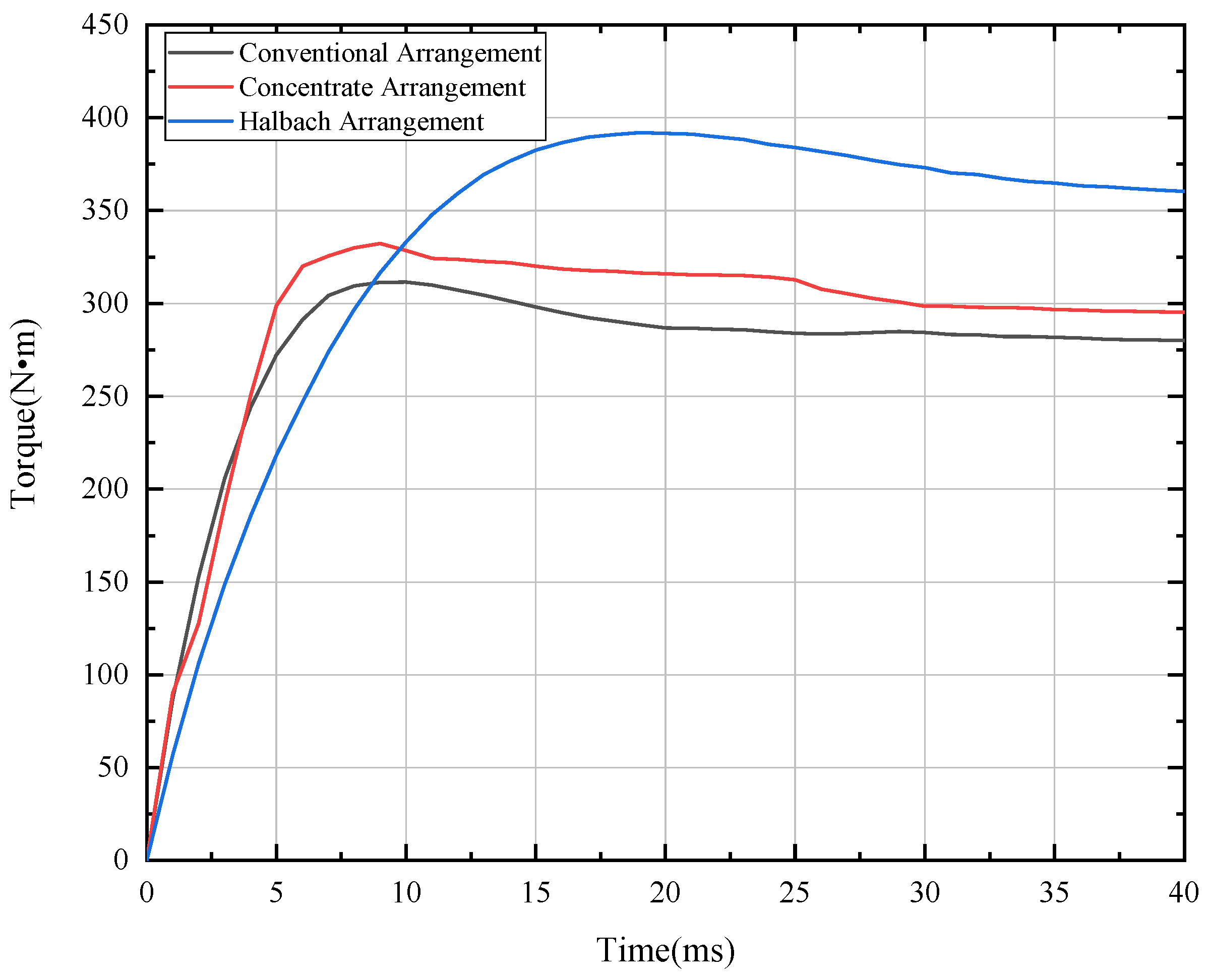
Since the permanent magnet governor is connected to a constant torque load, according to the energy conservation law, which can be obtained:
Simulation Model
The simulation model of the CPMG is built by using Maxwell Software, as shown in
Figure 5. It is mainly composed of a conductor rotor and a permanent magnet rotor, and a band motion domain. The conductor rotor contains a conductor barrel and a copper ring, where the copper ring is welded to the inner wall of the conductor barrel. The permanent magnet rotor contains a permanent magnet tray and PMs (NdFeB), where the permanent magnets are embedded in the permanent magnet array tray by means of a Halbach array. The number of PMs is 36. In addition, The band motion domain is a finite element mesh restriction and not an actual structure.
The material of the CPMG parts is given, of which the material of the conductor rotor and the permanent magnet rotor is Steel_1008, and the permanent magnet is selected N48H.
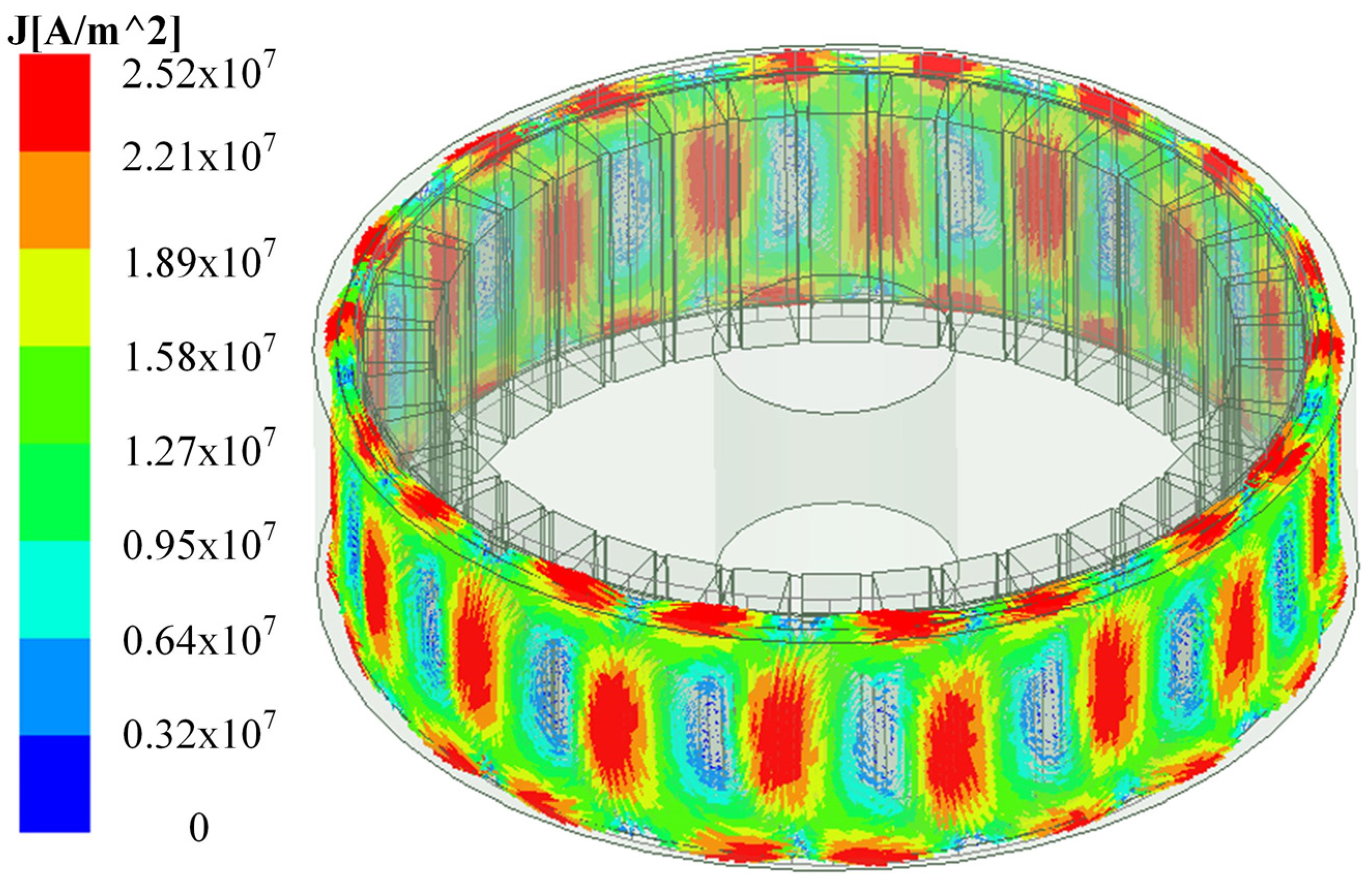
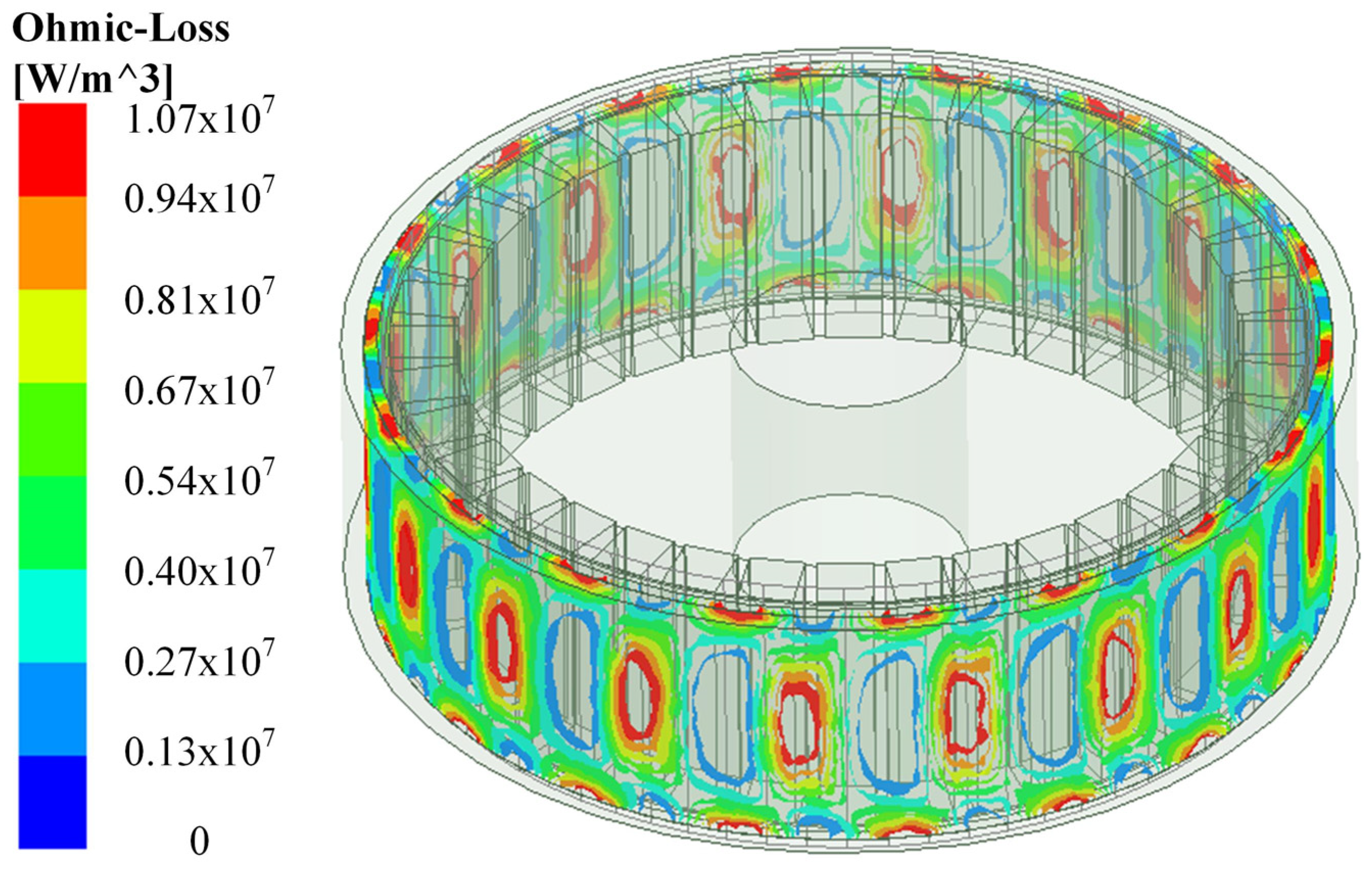
Due to the components of the copper ring, the induced currents in the copper ring are crucial for the transfer of the output torque to the CPMG. Therefore, it is particularly important to pay attention to the meshing subdivision of permanent magnets and the copper ring in the 3D FEM, as shown in
Figure 6. In order for the higher precision results to be obtained, the quality of meshing of CPMG should be above 0.3. Moreover, it should be noted that 3D FEM results with stabilization and convergence are taken as valid data, the residual error of which is less than the set value (
).


