1. Introduction
Analog IC design still relies on largely manual design entry and manual design iterations. Despite a variety of automation attempts that have been demonstrated, only a few have found their way into the broadly accepted industrial design environments. Simulation and schematic-level optimization is mainstream. Procedural generators automate device-level layouts and layout tools support designers interactively during manual design entry, e.g., by schematic-driven design or on-line design rule checking. All these tools, however, do not automate actual design or help with reusing circuitry but rather accelerate individual design steps. The lack of comprehensive automation, such as in the digital domain, still sets analog design productivity far behind.
In order to overcome this shortcoming, we propose a new method that enables analog design engineers to create procedural generators on their own and, thus, ease IP reuse. The method is based on procedural automation that utilizes generators at hierarchy levels far above device level. In addition, we overcome the need for programming generator code by means of automatic code generation. This enables designers to get a flexible generator in a matter of minutes. This way, parametric layout automation is made available without the former need to wait for expert generator programmers. We believe that this approach will significantly lower the entry barrier for utilizing analog generators by diminishing the former hurdle of initial generator programming. As a result, analog design engineers are enabled to leverage themselves and their individual analog designs.
1.1. Context of the Presented Work
Analog IC design can be broken down into many separate design steps that, however, are closely linked with each other. Much research has been conducted across these levels that would exceed the scope of this paper. Thus, we first clarify this work’s scope.
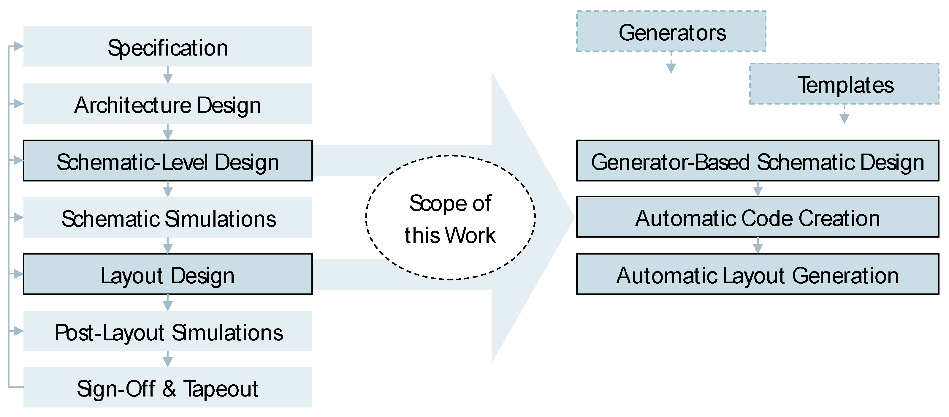
Figure 1 shows the simplified analog design flow and depicts this work’s focus on both schematic-level design entry and layout design. The automation approach is generator-based and, thus, is to be distinguished from synthesis methods (see below). While synthesis requires a sophisticated and complete set of constraints, generators must initially be programmed by EDA experts. Both constraints management and dedicated generator programming are significant entry barriers to the respective automation method. As an example, complex constraint management becomes adherent to enable synthesis methods [
1,
2,
3], while generator development requires significant development time. The latter was even considered a “paradigm shift” by the Berkeley Analog Generator (BAG) working group [
4].
We believe that a combined approach of both synthesis methods and procedural automation will pave the way towards full analog automation—in accordance with [
5]. As a step towards this goal, we address automatic code generation of procedural generators that automate layouts (plus schematic and symbol views) in a user-driven way, based on existing designs. In addition, we support various PDKs through abstraction of technology data [
6].
1.2. Our Contribution
We pursue increased flexibility of otherwise structurally relatively static analog layout generators. Former generators can only be adapted to new requirements by time-consuming programming. This work combines several recent advances in generator-based layout automation and implements a user-driven method that allows automatic generator creation in a matter of seconds. The new method utilizes the following recent advances:
Generator-based schematic design entry and cellview generation of building blocks that include the views symbol, schematic, and layout [
7],
Template-based extensions of generators in a matrix style [
8],
Template-based extensions of generators in a “street” style [
9],
Automatic generator code creation with a schematic as the input that allows immediate generation of non-hierarchical matrix-style layouts [
10].
Based on the previous advances mentioned above, the key contributions of this work are the following:
The new method creates generator code from an input schematic and automatically links layout instances to a variety of templates in order to control them.
Via a parameter mask, placement patterns, instance rotation, and routing channels can be defined by the user through adapting (template) parameters.
The new method creates hierarchical generators, each of which incorporates the aforementioned templates to ease layout flexibility through hierarchical composition.
As a result, our presented method allows the translation of a hierarchical schematic into an executable and hierarchical generator, which immediately provides several place and route options among a set of pre-defined place and route templates.
This way, early layout extraction can be carried out in order to analyze layout behavior very early in the design flow and accelerate design. Further manual rework of the generated layouts is fully supported, as the approach creates persistent cells and views in the design library.
2. State of the Art
This chapter presents a brief overview of the state of the art in the automation of analog IC design. A distinction is made between optimization-based
top-down and procedural generator-based
bottom-up approaches [
5] (We adopted the notations
top-down and
bottom-up from [
5], as this summarizes the methods’ natures in a concise form. However, it should be noted that these terms address the major nature while either of the methods might still utilize elements of the respective other approach.). We believe that templates are promising because they combine both methodologies (
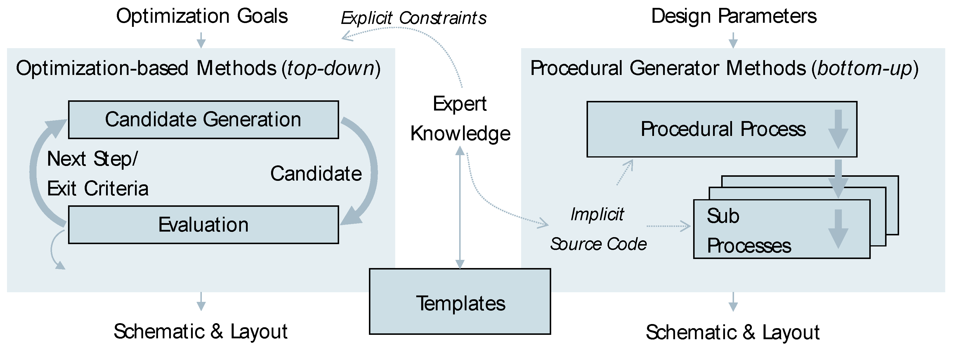
Figure 2). The respective advantages and disadvantages are discussed in the following subchapters.
2.1. Optimization
Optimization-based approaches are already available in commercial design environments for schematic sizing. Major design software vendors such as Cadence
® (San Jose, CA, USA), Synopsys
® (Mountain View, CA, USA), and Siemens EDA (Munich, Germany, former Mentor Graphics
®) offer tools that specifically “try” sizing variants of manually designed circuit topologies and, thus, automatically optimize them. In addition, companies such as MunEDA (Unterhaching, Germany) [
11] and Intento Design (Paris, France) [
12] have specialized in circuit optimization and analysis, respectively. In practice, optimization methods tend to be applied to smaller building blocks and components (e.g., standard cells or operational amplifiers), since larger circuits such as converters require too much computation time when optimized. Approaches to more systematic and multi-disciplinary design approaches are, therefore, the subject of further research [
5,
13,
14,
15].
In the area of optimization-based layout automation, there is still mostly academic work. In some cases, these are part of larger frameworks and, thus, also consider parasitic layout effects during circuit sizing (often called “layout-aware sizing”). Such approaches use so-called templates (see next subsection) [
16,
17,
18,
19], explore templates during runtime [
20,
21], or even synthesize layouts without the help of templates [
3]. In refs. [
22,
23], SWARM is presented which is an iterative method of self-organization for layout placement and wiring based on explicit and implicit specifications. With the recent rapid development of machine learning (ML), there are also ML-based optimization methods that can provide better results than previous optimization-based algorithms even at fewer iterations [
24]. Pulsic Animate™ (Bristol, UK) [
25] is a commercial tool for (partial) automatic layout synthesis based on a given hierarchical schematic. The typical circuit complexity is mostly in the spectrum of components, such as operational amplifiers or smaller building blocks.
2.2. Templates
Template-based layout methods are often used in the optimization-based approaches mentioned above. Templates restrict the solution space of the optimization problem. They are a special kind of constraint for specifying the floorplan and sometimes the routing of analog blocks in a knowledge-based way. The underlying method of template description, its implementation, and solving strategy (e.g., by evolutionary approaches) is the subject of research [
26,
27,
28,
29,
30]. As an example, the framework AIDA [
13] utilizes templates and combines many academic works, from optimization algorithms to layout automation used for various designs. Commercially, templates are used both by Jedat Inc. (Tokyo, Japan) for the automation of analog component layouts and basic building blocks [
31] and by Synopsys
® in their “Visually-Assisted Automation (VAA)” [
32].
Across the literature, however, the template methods differ. Therefore, [
33] first explicitly distinguished
symbolic and
geometrical templates. Symbolic templates are explicit geometric constraints, whereas geometric templates correspond to a parameterizable procedure (or “procedural generator”). According to the definition of our work, the geometric templates correspond to procedural generators. In ref. [
16], for example, the term “template” is used for a complex PCell with a pre-defined (programmed) arrangement. There, the template is merely the (graphical) representation of the layout arrangement implicitly programmed by an expert into the procedural generator code. Thus, we would classify it as a procedural generator that implements a static template.
2.3. Procedural Generators
In contrast to optimization-based approaches, the expert knowledge contained in procedural generators is not available explicitly (i.e., it is not machine-readable), e.g., in the form of constraints. The expert knowledge is
implicitly “hidden” in the procedural source code (
Figure 2). Procedural generators are, therefore, interpretable and executable, but the (implicit) decision paths they contain—the expert knowledge—are executed directly without being interpreted by the machine. The procedural generator, thus, does not “understand” the intention of the source code. With this implicit way of implementing generators, it is hardly possible to identify the described structure other than by analyzing the generator source code with a “keen eye”. If not using a dedicated API such as in refs. [
6,
7], there is no possibility to automatically extract abstract information of the layout arrangement from the procedural source code (e.g., as a return value of a method).
Furthermore, the (many) parameters used are very diverse and allow flexibility only according to the pre-programmed sequence, e.g., with respect to topology variants, sizing, or layout specifications. The complexity of the source code required for such flexibility quickly leads to high development efforts and costs, while such generators are difficult to maintain. For this reason, several methods were proposed that would diminish this shortcoming. On the schematic level, PCDS [
34] reduces the number of code lines that lead to the intended schematic creation results. For optimization, LAYGEN II improves device-level generation [
26]. With the Berkeley Analog Generator (BAG) [
4], a first open-source attempt covering a variety of target PDKs was presented. A second version of the BAG followed [
35], and new layout engines such as MESH [
8] for regular array-style layouts or LAYGO [
36] to especially support gridded FinFET layout styles were proposed.
The underlying trend we observe is that the level of abstraction increases through additional layers of ever more high-level layout description. This way, details are encapsulated, and rather the “what” than the “how” is implemented, i.e., we see a transition from implicit procedural approaches toward more explicit declarative approaches. We believe that in the long run, this is the pathway to combine procedural generators with optimization towards comprehensive synthesis methods.
3. Materials and Methods
Some of the underlying materials and methods used are covered by NDAs with semiconductor manufacturers. This includes details such as layout design rules, detailed layout information, or device parameters. In addition, the generator tool presented is proprietary. However, it can be made available upon request, for example, together with the technology setup available for the GPDK45 from the Cadence
® support website [
37].
Following, we describe the materials and methods used. For further detail,
Figure A1 in
Appendix A shows an excerpt of the automatically created generator code.
3.1. Generator Approach
3.1.1. Generator Framework
Details of the generator framework used are covered in ref. [
7]. The underlying concept is that persistent DRC-clean and LVS-clean cells are automatically generated from a single source generator through parametric and procedural code. Thus, a generator creates at least schematic, symbol, and layout for any given (building) block.
Key extensions towards (matrix-style) templates have been presented in refs. [
8,
10], of which the latter also creates generator code automatically for non-hierarchical matrix-style blocks. These extensions have been further developed in the presented work and now support both hierarchical blocks and further template styles.
3.1.2. Building Block Generators
The building block generators used are still implemented in an entirely procedural fashion. This means they do not yet rely on template-based generator code and are, thus, based on comprehensive source code developed by expert generator developers. Our library of building blocks especially contains blocks for (1) transistor arrangements, (2) capacitor arrangements, and (3) resistor arrangements. Examples of generated transistor building blocks for both a current mirror and a differential pair are shown in
Figure 3. All generators can be parameterized not only regarding device sizing but also regarding both topology variants (e.g., differential pair vs. current mirror) and layout arrangement (e.g., number of rows, placement pattern, routing options, or dummy devices) in a relatively flexible way. As the generators cover all relevant views (schematic, symbol, and layout), schematic-level design entry using generators already provides parameterized building block layouts.
3.2. Generator-Embedded Templates
Our new approach embeds templates into generators, especially at higher hierarchy levels. In this paper, template stands for the
machine-readable and
symbolic representation of a layout, independent of the concrete (computational) representation. A template, thus, does not exactly replicate the actual layout but specifies the constraints for its design. So, templates are abstract specifications for layout and, thus, independent of a specific technology.
Figure 4 shows an example of a template represented by both a floorplan and a slicing tree, which have already been used in “template”-based analog layout synthesis [
16]. Slicing trees model slicing floorplans using binary trees. These trees are graphs that fan out from the “root” towards the “leaves”, as often used in EDA [
38].
Specifically, we propose two major templates, which we believe can cover a majority of layout arrangements when utilized hierarchically. They represent layout arrangements in a matrix style as well as in a street style. While the matrix style represents arrangements using mathematical matrices, the street style implements an upper instance row and a lower instance row connected via a central routing bus. The latter is represented by tuples of instance identifiers as well as net names.
Besides such regular templates, non-regular (more flexible) templates can be defined. They can be categorized into slicing floor plans and non-slicing floor plans [
38,
39,
40]. However, either of them is not considered in the design methodology presented in this paper. The reason is that by using regular templates, we can (1) implement the templates straightforwardly using object-oriented source code without the need of a solver, as in ref. [
30], and (2) we can easily include routing channels represented as placeable pseudo instances in an object-oriented way that allows flexible adaptation of their size through hierarchical composition using the composite design pattern. The template styles are depicted in
Figure 5.
3.3. Generator Code Creation
Designing generators is time-consuming and can, depending on the circuit size, easily require weeks to months of programming. Thus, we developed automatic creation of generator code with the schematic and symbol as the input. As output, a generator (i.e., its source code) is automatically created that parametrically (re-)creates the input views. In addition, it also creates a layout view. Thereby, the layout creation process is controlled by the template system which is embedded into the generator code.
3.3.1. The Generator Programming Interface (API)
The generator programming interface implements generators in a common way that inherits from a generator parent class. Each generator follows the same structure and implements the following methods (see an excerpt of the generated code for a high-pass filter (HPF) example in
Appendix A which contains the following methods and instance identifiers):
The procedure param_check() is used to define all parameters shown in the user interface. For this purpose, initial instances of objects might also be defined, including default settings for parameters. Each parameter has constraints attached, including choice constraints or range constraints.
The checking of parameters in the context of others happens in method param_check(). Here, callbacks are defined that run at any parameter change in order to, e.g., derive parameter values from each other, (de)activate parameter entry, or raise error messages to send hints to the user interface so that users can react.
In order to unify the parameters across the views, method prepare() collects view-overarching information such as instances, nets, or terminals (pins). This way, subsequent procedures can use the pre-defined information via methods which systematically reduces the likelihood of LVS issues.
The actual view definitions of the cell to be generated are provided in methods with the respective view name. Thus, schematic, symbol, and layout are implemented in individual methods. They might be deselected by the user in order to exclude them from the generator run if not required.
Please note that the integration of the templates is implemented via the object instance
self.tpl (see
Figure A1 in
Appendix A) already defined in the method
param_check(). This allows for user-driven interaction and immediate feedback (e.g., matching patterns or error messages). Once the parameters are defined and the user runs the generator, the template responses to the instance details that are available after instance generation. This way, the template adapts and executes placement and routing of the subblocks.
3.3.2. The Generator Creator Flow
The Generator Creator translates a given hierarchical schematic-level design into a hierarchical template-based generator which also generates the layout view. The flow with its major steps is shown in
Figure 6. From a user’s perspective, a separate tool is run, whose default settings are set in such a way that the behavior presented in this paper is immediately executed. Further options, for example, allow instances to be handled as they are (i.e., they are not converted into a sub generator).
3.4. Result Quantification Approach
A major challenge in comparing analog EDA approaches is the lack of benchmarks. To the best of our knowledge, there is no common quantification measure defined that allows for comparing our method against other methods. Therefore, we combine quantitative measures, including the number of code lines, generator run time, and the number of circuit instances with qualitative measures, such as the nature of the method, properties of the method, and usability aspects. Despite not being optimal, we believe that this is the best attempt to treat the lack of benchmarks (as well as the heavily NDA-restricted environment). Future work should elaborate further on the aforementioned limitations.
4. The Method and Results
4.1. The Example Circuit
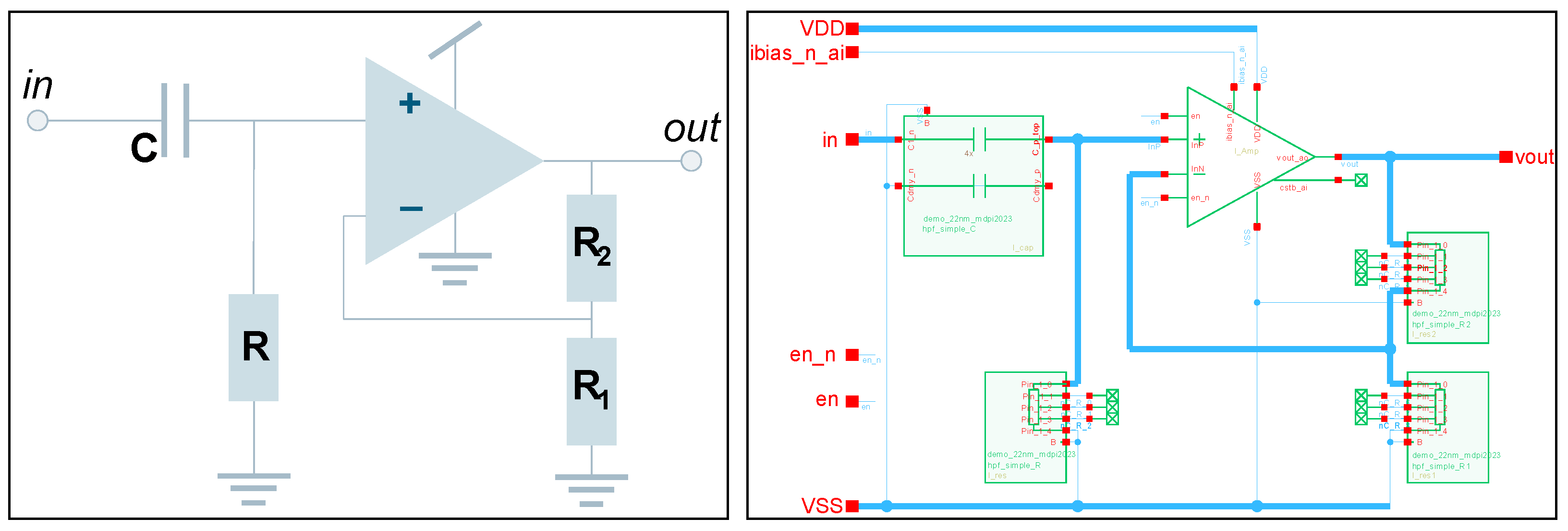
In order to demonstrate the method, we selected a simple high-pass filter (HPF) as the input schematic. As the filter behavior depends on the parameters of the passive devices, this is likely a good example of a recurrent and parametric design task. Other relevant circuits could be blocks such as LDOs for various loads, different pipeline stages for data converters, or operational amplifiers.
The example circuit consists of a simple first-order RC high-pass followed by an amplifier with resistive feedback. It is implemented with the building block generator approach mentioned in
Section 3.1, resulting in the schematic given in
Figure 7 (with a block diagram given, too). The amplifier in the HPF is also implemented using generators. As all building block generators create the corresponding layouts (besides schematic and symbol), the respective building block layouts are already immediately available during the schematic design entry. At this stage, they are still unconnected when changing to the layout view (
Figure 8). Nevertheless, the generators encapsulate device-level details such as matching placement patterns, routing layers, wire sizes, and substrate connections.
4.2. The Generator Creation Process
Given the generator-based hierarchical schematic with automated building blocks described in
Section 4.1, the Generator Creator flow is executed. It creates a new top-level generator based on the schematic input. In addition, this generator embeds the template method described in
Section 3.2. As a result, a new generator is available which not only parametrically (re-)generates the input schematic but also generates an LVS-clean layout according to user inputs regarding placement pattern (within the limits of the template selected) and routing parameters (i.e., layers, widths, and spacings). This flow from schematic to new generator is fully automated and does not require any programming. The steps of the generator-creator flow are depicted in
Figure 9 (which refines
Figure 1). In order to reach a LVS-clean result, a few generator runs might be required in order to fine-tune the parameters of both the building block generators and the top-level placement. The steps of the whole process are as follows:
First, the schematic entry is completed in a manual design fashion, starting with an empty schematic. Generators are used to encapsulate basic building blocks that also allow defining details of the building blocks mainly including device sizing. In addition, it also includes proper parameterization of the layout generation process such that the shapes of the building blocks, their rotation with respect to instance pins as well routing options are prepared for block assembly on the level above.
Second, the actual code creation step is executed via a user interface that is accessible in the design environment (here: Cadence® (San Jose, CA, USA), Virtuoso® (San Jose, CA, USA)). The code creation step automatically runs the following steps:
Thid, in order to create the layout, the automatically created generator can be run immediately to use it in a similar way as the building block generators before:
The new generator inherits the parameters of the sub-generators and, thus, provides full parametric control across the hierarchy.
Each hierarchy level incorporates templates for placement and routing options in order to flexibly define placement patterns, e.g., the order of wires in the routing channel.
The actual layout, including schematic and symbol, is (re)generated according to the user’s inputs.
4.3. User Interface and Generator Parameterization of the Placement Pattern
When running the automatically created generator, various parameters across the generator hierarchy can be defined. Besides device-level details such as sizing, placement, and routing, these can be controlled through the user interface. The basis for this is the flexibility of the respective template that was selected (here: street).
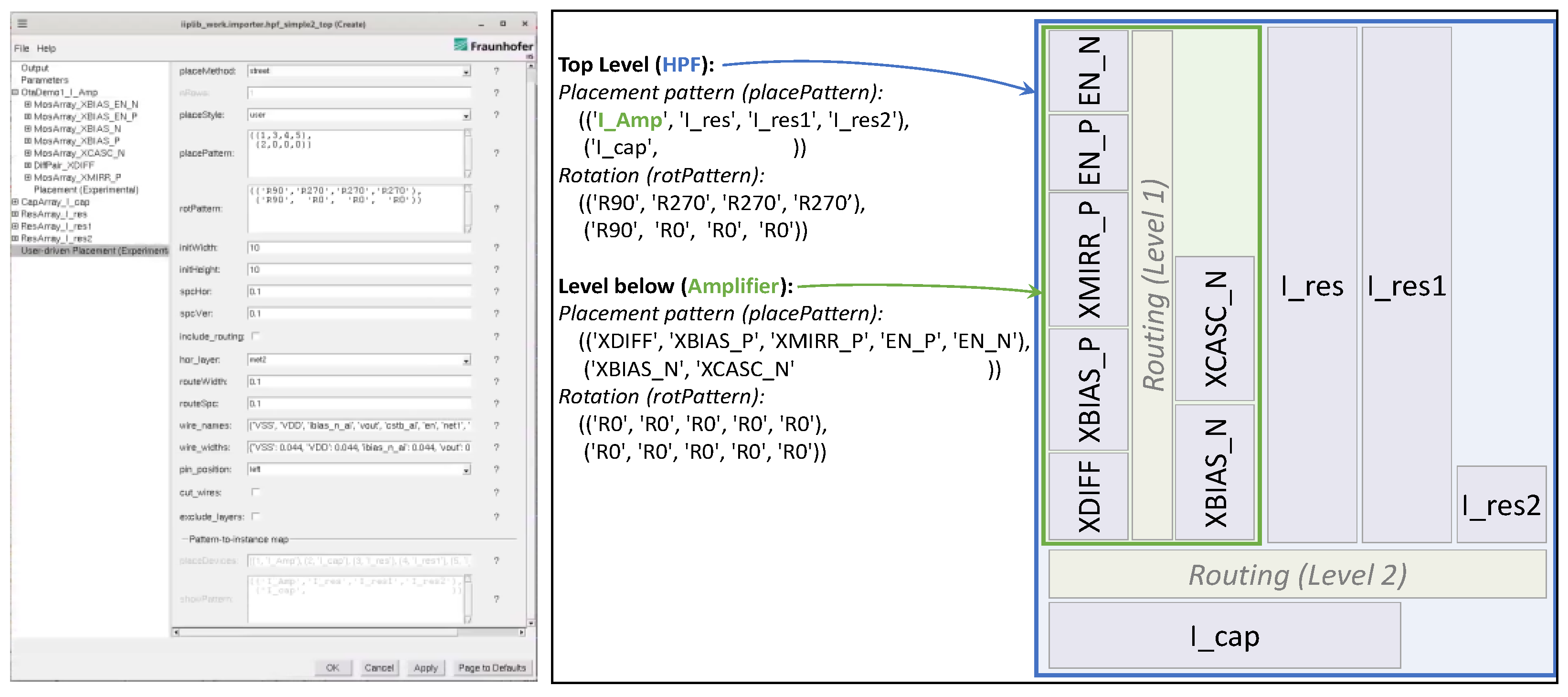
The relation between parameters, template, and user interface is illustrated in
Figure 10. The hierarchies of both amplifier “I_Amp” and high-pass filter (HPF) (both indicated by colors) can be edited through the top-level GUI. For example, the lower hierarchy level of the amplifier can be adjusted regarding the placement pattern by providing another tuple of lists for both placement rows in the street template. Similarly, the top-level pattern can be edited while the amplifier generates a hierarchy level below. In addition, various details of all building blocks can be changed (see
Section 3.1.2).
4.4. Layout Variant Generation and Simulation
Using the automatically created generator, we generated different layout variants of the amplifier and a simple HPF that includes these amplifiers. The HPF placement is defined according to the abstract arrangement given in
Section 4.3. All placement variants are intended to test both the layout-level flexibility and the hierarchy support of the method. Additionally, it is to identify the runtime as well as the limitations of both the building block generators (that do not yet utilize the presented template method but full procedural programming) and the automated generator.
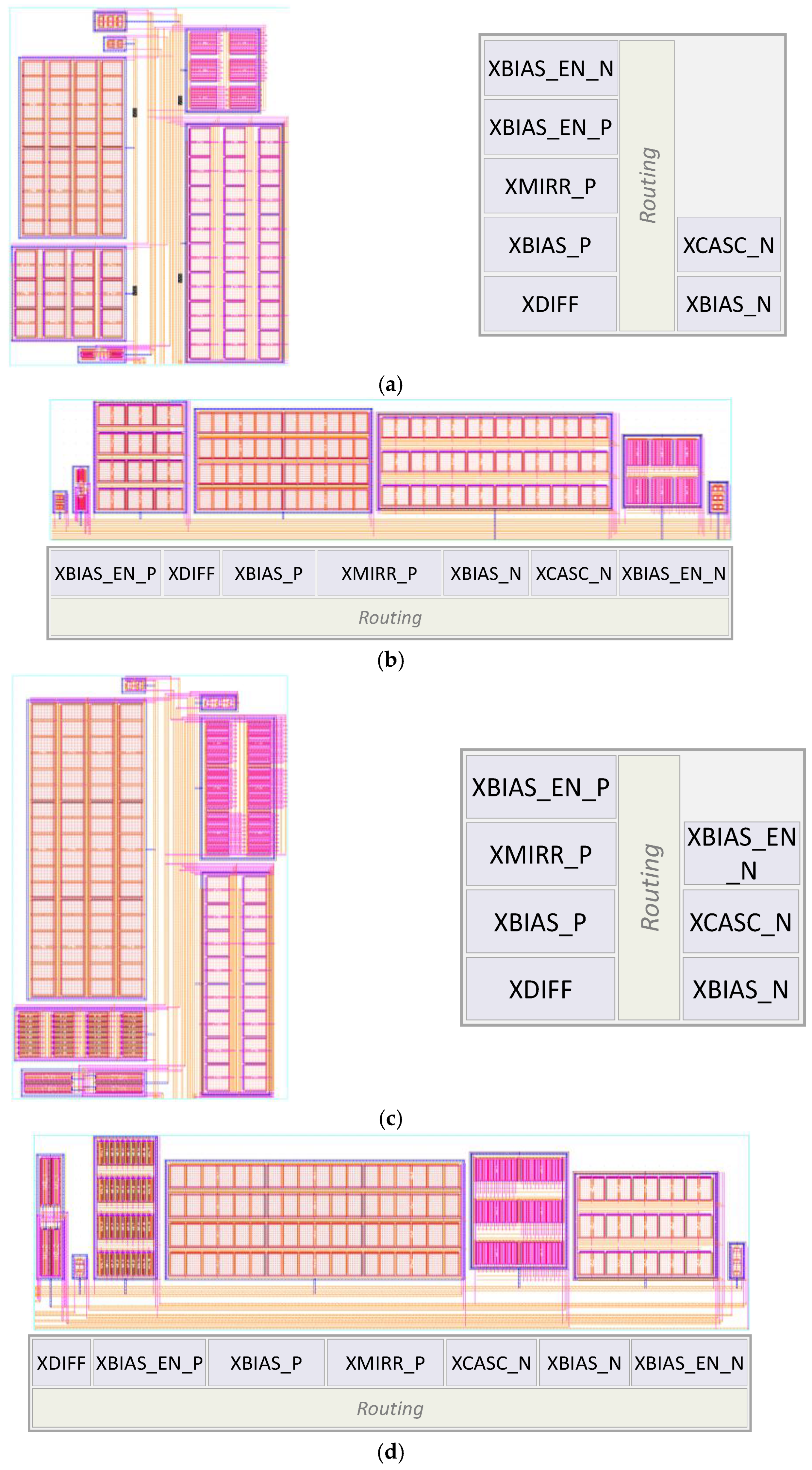
The amplifier variants implemented are based on two different parameter sets: low power, “LP”, and higher bandwidth, “Speed”. Layout details of the amplifiers are shown in
Appendix B. There, it can be seen that both the sizing and arrangement patterns of the building blocks as well as the overall arrangement can be controlled by the generator in a flexible way (trough adapting the template). While
Figure A2a,c show the street arrangement with two rows (note that in these cases the arrangement is rotated by 90°, thus, the rows of the templates appear as columns),
Figure A2b,d show each of them with one row.
Even though this paper does not focus on the particular circuit but on the EDA method, simulations were run in order to help evaluate the method. The generated amplifier layouts were simulated post-layout and compared with the schematic level.
Table 1 lists these simulation results and shows the deviations of the layout variants related to the respective schematic. However, it is not possible to derive generalized statements from it, as analog circuit performances largely depend on the context in which they are used.
In order to further evaluate the hierarchical approach, both generated sizing variants of the amplifier were applied to the aforementioned HPF example from
Section 4.1. Using the abstract placement pattern from
Section 4.3, two layout variants were generated with the automatically created generator. The resulting layouts are shown in
Figure 11. One can see both the different amplifiers at the upper left of the layouts as well as differences in the sizing of the capacitance arrays at the bottom, which is intended to get a more rectangular overall shape.
Both layouts were simulated. The frequency behavior is given in
Figure 12, and further performances are listed and compared in
Table 2.
4.5. Quantitative and Qualitative Measures of the EDA Method
As mentioned in
Section 3.4, comparing analog EDA methods is very limited. To the best of our knowledge, there are no benchmarks available for analog EDA. Thus, we evaluate the following aspects of the method: type of the generator, flexibility of the generator, lines of generator code, time to generator code, and cumulative generator runtime. The evaluation results are given in
Table 3. All investigated runtimes were carried out on a server with a Xeon E5-2637v3 CPU.
While creating the test circuits, the parametrization of generators allows to both resize the building blocks and adapt their aspect ratios in a matter of seconds. On the level of the amplifier, this accounts for about 40 s, and the whole HPF takes about 120 s.
Running and adapting the generators works well when changing the placement pattern or sizing values. Limitations, however, occur if topology parameters are changed during the generation process (e.g., number of branches of a current mirror block). The reason for this is the change of the netlist, which is not yet flexible in the generator after automatic code creation. Therefore, the user cannot edit the netlist via parameters and, thus, either has to adapt the generator code or—more user-friendly—has to rerun the Generator Creator so that an updated generator is available with a new topology and netlist.
4.6. Comparison with other EDA Methods
Comparing analog EDA methods is challenging, as, to the best of our knowledge, there are no benchmarks available yet (which would be a valuable contribution). Thus, we compare our method qualitatively with other existing analog EDA methods in order to get a picture of its features.
Procedural approach: Our method is a procedural generator-based approach comparable to the Berkeley Analog Generator (BAG) [
4,
35] when considering building block generators. Our method also allows the development of more complex generators [
7], but the initial effort of generator development turned out to be critically large for large designs.
Template approach: Our method also incorporates the template approach in order to diminish the limitations of pure procedural approaches. Thus, the definition of the arrangement is comparable to the placement definition in AIDA [
18] or the Layout Description Script LDS [
28]. However, in contrast to AIDA and LDS, we do not utilize optimization to find a placement solution but rather heavily constrain the placement by the template. The template patterns “street” and the matrix style MESH [
8] are implemented by the object-oriented composite design pattern such that all abstract positions can be directly addressed and instances attached. Depending on the instance sizes, the template elements are adapted, which aggregate along rows and columns from lower hierarchy levels to upper levels. Thus, all placements are inherently legalized, and routing is enabled by the pre-defined and also flexible routing channel. The hierarchical approach effectively forms a slicing tree.
Optimization: The presented method does not apply optimization. It is rather intended to be controlled by the user. Optimizers, such as WiCkeD™ from MunEDA (Unterhaching, Germany) [
11], or sizing exploration, such as from Intento Design [
12], could, however, be utilized by the user. Users can setup their individual optimization flows with scripts that parameterize the generator via the command line (which is another mode besides the GUI mode).
5. Discussion
The problem class: The presented work addressed the problem of the initial efforts required to set up analog integrated design automation. From the major analog EDA directions, namely synthesis and procedural generators, the latter was investigated in order to reduce the initial programming efforts.
The solution concept: The presented approach combines several existing methods into a novel user-driven flow. This differentiates our method from work that solely focusses on programming schemes or algorithms as support for EDA programmers. We attempt to solve the problem by using automatic code creation constrained by pre-defined templates.
The scalability: The templates can be selected flexibly via the user interface, which is automatically generated. In addition, they are implemented in a separate template system. This way, extensions in functionality do not require changes in the generator but only centralized updates in the template system. When utilized across a variety of generators, all (new) template functionalities (e.g., new template styles or algorithms for P&R) are automatically available across these generators. The code for typical layout design tasks is, therefore, well reusable, and maintenance is significantly eased by means of proper separation of data and procedure.
The potential EDA community effect: Through the separation of data and procedures, it is possible to provide the template interface definitions and related algorithms as open-source code. If adopted by the community, a (quasi) standard can evolve through a variety of individual contributions. This way, a library of templates can evolve, and benchmarks could be defined in a machine-readable way across EDA tools.
The potential in analog IC design: A major limitation of former analog layout generators is their initial development time. This often leads to the economically driven decision not to adapt them for productive design projects. To the best of our knowledge, our presented approach is the first to propose a fully user-driven way of creating hierarchical and flexible generators to overcome the need for programming generator code (which is sometimes also realized in a graphical way such as in ref. [
42]). This sets the entry barrier for utilizing procedural generators significantly lower: in an iterative process, design engineers can design schematics using building block generators, parameterize them, and then run the Generator Creator to get a hierarchical generator immediately. By parameterizing the new generator’s layout pattern, rapid layout prototyping is enabled, and early parasitic extraction will help design engineers taking decisions fast.
The limitation to analog IC design: So far, the approach cannot provide every possible placement or routing pattern, as it is limited to the capabilities the templates provide. Thus, specific requests of designers might not be covered yet, and manual edits based on the generated results will still be necessary. In order to improve the quality of the generated layout, the library of templates must be extended, ideally using a community effect. We strongly suggest to establish an analog EDA community for sharing automation attempts and actual code in order to join efforts on common ground that allows broader re-usability and adoption.
The next steps: Future research should refine the approach regarding the following aspects:
The proposed method works best with schematics that, ideally, include generated building blocks. This, however, is in contrast with the “flat” schematic level design approach. Thus, user-driven conversion of flat designs into ones with generated building blocks instead should be considered.
A source design might already contain a layout (e.g., when whole IPs are migrated). Therefore, algorithms should be investigated that translate static input layouts into abstract template representations. These templates would then guide the hierarchical layout generator automatically.
The given set of templates is still limited and should be extended to include further styles. In order to ease the creation of a template library, an open approach should be provided, e.g., by providing an open-accessible API description.
The presented routing scheme follows a straight-forward row-based pattern with a list of net names as the input. Algorithms that allow automatic and analog-aware routing are, thus, desirable and, ideally, open-access.
6. Conclusions and Outlook
This work presents a novel approach to combining procedural generators, flexible templates, and automatic generator code creation in a hierarchical way. As a prerequisite, a template-based approach for the explicit and flexible top-down description of generators was developed. Currently, two basic template styles are available, and further ones will be the topic of future work. The template approach increases the flexibility of otherwise relatively structure-static procedural generators, as respective strengths are supplemented and the weaknesses compensated. While procedural generators create layout details and also realize entire analog basic blocks automatically, templates allow flexible and abstract layout description and processing. The new combination of these methods allows both user-driven description and automation of hierarchical layouts in a fashion that does not require programming any code. With this method, the otherwise time-consuming programming of generators can be automated entirely, enabling rapid parasitic extraction early in the design process.
Our approach does not yet claim to produce best-in-class layouts. The focus, however, is on rapid generator code creation to provide designers early layout insights by means of almost instant layout automation. With this, clean layouts and parasitic extraction can be achieved in a matter of about 10 minutes to a few hours (when generators are used for schematic entry and both topology and initial sizing are available). In addition, the post-layout simulations show reasonable performance for the selected examples. Thus, we believe that our approach will enable designers both to improve decision-making in the early (schematic-level) design phase and to automate layout design steps.
As the templates are organized independently of the concrete generators, updates in the template system can be deployed to existing generators. This means that new algorithms at the level of templates will gradually improve the generated results (e.g., other placement and routing schemes, algorithms for parameter optimization, or estimation methods; in our example above, the routing scheme was updated this way). So, abstract and PDK-agnostic templates should become available to the research community in order to better spread knowledge in this comparably small and also highly NDA-restricted community and pave the way for more closely linked EDA research and developments.
Author Contributions
Conceptualization, B.P.; methodology, B.P., U.E., U.H.; software, U.E., B.P.; validation, U.E., B.P.; formal analysis, B.P.; investigation, B.P., U.E.; data curation, U.E., B.P.; writing—original draft preparation, B.P.; writing—review and editing, U.H., U.E., B.P.; visualization, B.P., U.E.; supervision, B.P.; project administration, B.P.; funding acquisition, B.P. All authors have read and agreed to the published version of the manuscript.
Funding
This research was funded by the German Federal Ministry of Education and Research (BMBF) within the frame of the HoLoDEC project, grant number 16ME0700. The article processing charge (APC) was funded by the Fraunhofer-Gesellschaft.
Data Availability Statement
Not applicable. In general, IC design is both very NDA-restricted and based on special closed-source design tools. Current activities towards open access IC design and EDA are, however, evolving and will be considered in future.
Acknowledgments
We would like to thank all our colleagues that contributed to the development of the former Generator Creator version which we extended such that it now supports templates.
Conflicts of Interest
The authors declare no conflict of interest. The funders had no role in the design of the study; in the collection, analyses, or interpretation of data; in the writing of the manuscript, or in the decision to publish the results.
Appendix A
Simplified Selection of the Automatically Created Code of the HPF Generator
Figure A1.
Representative and simplified selection of the generator code that was automatically created by the method presented in this work. Note that the template self.tpl connects parameter entries of the user (method param_check()) with layout generation (method layout()).
Figure A1.
Representative and simplified selection of the generator code that was automatically created by the method presented in this work. Note that the template self.tpl connects parameter entries of the user (method param_check()) with layout generation (method layout()).
Appendix B
Example Layouts Generated by the Amplifier Generator
Figure A2.
Generated layout examples (in a 22 nm technology) of amplifier variants by utilizing the presented method of template-based automatic generator code creation. Results for sizing “LP” are shown in (a,b) and results for sizing “Speed” are shown in (c,d). Besides sizing, the generated layouts are varied regarding placement patterns (street with one row and once with simpler routing vs. two rows and different arrangements each) and rotation patterns.
References
- Krinke, A.; Horst, T.; Glaser, G.; Grabmann, M.; Markus, T.; Prautsch, B.; Hatnik, U.; Lienig, J. From Constraints to Tape-Out: Towards a Continuous AMS Design Flow. In Proceedings of the 2019 IEEE 22nd International Symposium on Design and Diagnostics of Electronic Circuits & Systems (DDECS), Cluj-Napoca, Romania, 24–26 April 2019; pp. 1–10. [Google Scholar]
- Krinke, A. Constraint Propagation for Analog and Mixed-Signal Integrated Circuit Design; Fortschritt-Berichte VDI, Reihe 20, Nummer 474; Dissertation, TU Dresden: Dresden, Germany, 2020; ISBN 978-3-18-347420-2. [Google Scholar]
- Habal, H.; Graeb, H. Constraint-Based Layout-Driven Sizing of Analog Circuits. IEEE Trans. Comput.-Aided Des. Integr. Circuits Syst. 2011, 30, 1089–1102. [Google Scholar] [CrossRef] [Green Version]
- Crossley, J.; Puggelli, A.; Le, H.-P.; Yang, B.; Nancollas, R.; Jung, K.; Kong, L.; Narevsky, N.; Lu, Y.; Sutardja, N.; et al. BAG: A Designer-Oriented Integrated Framework for the Development of AMS Circuit Generators. In Proceedings of the 2013 IEEE/ACM Int. Conf. on Computer-Aided Design (ICCAD), San Jose, CA, USA, 18–21 November 2013; pp. 74–81. [Google Scholar] [CrossRef]
- Scheible, J.; Lienig, J. Automation of Analog IC Layout—Challenges and Solutions. In Proceedings of the 2015 Symposium on International Symposium on Physical Design (ISPD’15), Monterey, CA, USA, 29 March–1 April 2015; pp. 33–40. [Google Scholar] [CrossRef] [Green Version]
- Prautsch, B.; Eichler, U.; Reich, T.; Puppala, A.; Lienig, J. Abstract Technology Handling for Generator-Based Analog Circuit Design. In Proceedings of the GMM-Fachbericht 83, Reliability by Design (ZuE 2015), Siegen, Germany, 21–23 September 2015; pp. 56–61, ISBN: 9783800740710. [Google Scholar]
- Prautsch, B.; Eichler, U.; Rao, S.; Zeugmann, B.; Puppala, A.; Reich, T.; Lienig, J. IIP Framework: A Tool for Reuse-Centric Analog Circuit Design. In Proceedings of the 13th International Conference on Synthesis, Modeling, Analysis and Simulation Methods and Applications to Circuit Design (SMACD 2016), Lisbon, Portugal, 27–30 June 2016; pp. 1–4, ISBN: 978-1-5090-0490-4. [Google Scholar]
- Prautsch, B.; Eichler, U.; Reich, T.; Lienig, J. MESH: Explicit and Flexible Generation of Analog Arrays. In Proceedings of the 2017 14th International Conference on Synthesis, Modeling, Analysis and Simulation Methods and Applications to Circuit Design (SMACD), Giardini Naxos, Italy, 12–15 June 2017; pp. 1–4. [Google Scholar] [CrossRef]
- Eichler, U.; Prautsch, B.; Reich, T. Automated Creation of Reusable Generators for Analog IC Design with the Intelligent IP Method. In Proceedings of the DVCon Europe, Munich, Germany, 7 December 2022. [Google Scholar]
- Prautsch, B.; Wittmannm, R.; Eichler, U.; Hatnik, U.; Lienig, J. Generators, Templates, and Code Generation for Flexible Automation of Array-Style Layouts. In Proceedings of the International Conference on Synthesis, Modeling, Analysis and Simulation Methods and Applications to Circuit Design (SMACD 2021), Online, 19–22 July 2021; pp. 180–183. [Google Scholar]
- MunEDA. Circuit Sizing & Tuning With MunEDA WiCkeD (TM). Available online: https://www.muneda.com/circuit-sizing-and-optimization-tools/ (accessed on 24 January 2023).
- Intento Design. ID-Xplore. Available online: https://www.intento-design.com/products/id-xplore/ (accessed on 24 January 2023).
- AIDASoft. Analog Integrated Circuit Design Automation. Available online: https://www.aidasoft.com/Home (accessed on 24 January 2023).
- Prautsch, B.; Dornelas, H.; Wittmann, R.; Henkel, F.; Schenkel, F.; Koelsch, J.; Grimm, C.; Strube, G. AnastASICA—Towards Structured and Automated Analog/Mixed-Signal IC Design for Automotive Electronics. In Proceedings of the ANALOG 2020; 17th ITG/GMM-Symposium, Online, 28–30 September 2020; pp. 1–6, ISBN: 978-3-8007-5335-2. [Google Scholar]
- Martins, R.; Lourenco, N.; Horta, N.; Yin, J.; Mak, P.-I.; Martins, R.P. Many-Objective Sizing Optimization of a Class-C/D VCO for Ultralow-Power IoT and Ultralow-Phase-Noise Cellular Applications. IEEE Trans. Very Large Scale Integr. (VLSI) Syst. 2019, 27, 69–82. [Google Scholar] [CrossRef]
- Castro-Lopez, R.; Guerra, O.; Roca, E.; Fernandez, F.V. An Integrated Layout-Synthesis Approach for Analog ICs. IEEE Trans. Comput. -Aided Des. Integr. Circuits Syst. 2008, 27, 1179–1189. [Google Scholar] [CrossRef]
- Lourenço, N.; Martins, R.; Horta, N. Layout-Aware Sizing of Analog ICs Using Floorplan & Routing Estimates for Parasitic Extraction. In Proceedings of the 2015 Design, Automation Test in Europe Conf. Exhibition (DATE), Grenoble, France, 9–13 March 2015; pp. 1156–1161. [Google Scholar]
- Martins, R.; Lourenco, N.; Canelas, A.; Povoa, R.; Horta, N. AIDA: Robust Layout-Aware Synthesis of Analog ICs Including Sizing and Layout Generation. In Proceedings of the 2015 International Conference on Synthesis, Modeling, Analysis and Simulation Methods and Applications to Circuit Design (SMACD), Istanbul, Turkey, 7–9 September 2015; pp. 1–4. [Google Scholar] [CrossRef]
- Chang, H.; Chen, Y.; Yeh, C.; Liu, C.J. Layout-Aware Analog Synthesis Environment with Yield Consideration. In Proceedings of the Sixteenth International Symposium on Quality Electronic Design, Santa Clara, CA, USA, 2–4 March 2015; pp. 589–593. [Google Scholar] [CrossRef]
- Martins, R.; Canelas, A.; Lourenço, N.; Horta, N. On-the-Fly Exploration of Placement Templates for Analog IC Layout-Aware Sizing Methodologies. In Proceedings of the 2016 13th International Conference on Synthesis, Modeling, Analysis and Simulation Methods and Applications to Circuit Design (SMACD), Lisbon, Portugal, 27–30 June 2016; pp. 1–4. [Google Scholar] [CrossRef]
- Jangkrajarng, N.; Zhang, L.; Bhattacharya, S.; Kohagen, N.; Shi, C.-J.R. Template-Based Parasitic-Aware Optimization and Retargeting of Analog and RF Integrated Circuit Layouts. In Proceedings of the 2006 IEEE/ACM International Conference on Computer-Aided Design ICCAD ’06, San Jose, CA, USA, 5–9 November 2006; pp. 342–348. [Google Scholar] [CrossRef]
- Marolt, D.; Scheible, J.; Jerke, G.; Marolt, V. SWARM: A Multi-Agent System for Layout Automation in Analog Integrated Circuit Design. In Agent and Multi-Agent Systems: Technology and Applications; Springer International Publishing: Cham, Switzerland, 2016; pp. 15–31. ISBN 978-3-319-39883-9. [Google Scholar]
- Marolt, D. SWARM: A Novel Methodology for Integrrated Circuit Layout Automation Based on Principles of Self-Organization; Fortschritt-Berichte VDI: Düsseldorf, Germany, 2020; Reihe 20, Nr. 475; ISBN 978-3-18-347520-9. [Google Scholar]
- Huang, G.; Hu, J.; He, Y.; Liu, J.; Ma, M.; Shen, Z.; Wu, J.; Xu, Y.; Zhang, H.; Zhong, K.; et al. Machine Learning for Electronic Design Automation: A Survey. ACM Trans. Des. Autom. Electron. Syst. 2021, 26, 1–46. [Google Scholar] [CrossRef]
- Pulsic, Pulsic Animate™. Available online: https://pulsic.com/animate/ (accessed on 24 January 2023).
- Martins, R.; Lourenco, N.; Horta, N. LAYGEN II—Automatic Layout Generation of Analog Integrated Circuits. IEEE Trans. Comput.-Aided Des. Integr. Circuits Syst. 2013, 32, 1641–1654. [Google Scholar] [CrossRef]
- Unutulmaz, A.; Dundar, G.; Fernandez, F.V. A Template Router. In Proceedings of the 2011 20th European Conference on Circuit Theory and Design (ECCTD), Linkoping, Sweden, 29–31 August 2011; pp. 334–337. [Google Scholar] [CrossRef]
- Unutulmaz, A.; Dundar, G.; Fernandez, F.V. LDS—A Description Script for Layout Templates. In Proceedings of the 2011 20th European Conference on Circuit Theory and Design (ECCTD), Linkoping, Sweden, 29–31 August 2011; pp. 857–860. [Google Scholar] [CrossRef]
- Pan, P.-C.; Chin, C.-Y.; Chen, H.-M.; Chen, T.-C.; Lee, C.-C.; Lin, J.-C. A Fast Prototyping Framework for Analog Layout Migration With Planar Preservation. IEEE Trans. Comput. -Aided Des. Integr. Circuits Syst. 2015, 34, 1373–1386. [Google Scholar] [CrossRef]
- Prautsch, B.; Hatnik, U.; Eichler, U.; Lienig, J. Template-Driven Analog Layout Generators for Improved Technology Independence. In Proceedings of the ANALOG 2018; 16th GMM/ITG-Symposium, Munich/Neubiberg, Germany, 13–14 September 2018; pp. 156–161, ISBN: 978-3-8007-4754-2. [Google Scholar]
- Jedat Inc. LSI Design Solution. Available online: https://www.jedat.co.jp/en/products/semi_design/semi_layout_design/ (accessed on 24 January 2023).
- Synopsys®. Custom Compiler. Available online: https://www.synopsys.com/implementation-and-signoff/custom-design-platform/custom-compiler.html (accessed on 24 January 2023).
- Jangkrajarng, N.; Bhattacharya, S.; Hartono, R.; Shi, C.-J.R. IPRAIL—Intellectual Property Reuse-Based Analog IC Layout Automation. Integr. VLSI J. 2003, 36, 237–262. [Google Scholar] [CrossRef]
- Marolt, D.; Greif, M.; Scheible, J.; Jerke, G. PCDS: A New Approach for the Development of Circuit Generators in Analog IC Design. In Proceedings of the 22nd Austrian Workshop on Microelectronics (Austrochip), Graz, Austria, 9 October 2014; pp. 1–6. [Google Scholar] [CrossRef]
- Chang, E.; Han, J.; Bae, W.; Wang, Z.; Narevsky, N.; NikoliC, B.; Alon, E. BAG2: A Process-portable Framework for Generator-based AMS Circuit Design. In Proceedings of the 2018 IEEE Custom Integrated Circuits Conference (CICC), San Diego, CA, USA, 8–11 April 2018; pp. 1–8. [Google Scholar] [CrossRef]
- Han, J.; Bae, W.; Chang, E.; Wang, Z.; Nikolic, B.; Alon, E. LAYGO: A Template-and-Grid-Based Layout Generation Engine for Advanced CMOS Technologies. IEEE Trans. Circuits Syst. I Regul. Pap. 2021, 68, 1012–1022. [Google Scholar] [CrossRef]
- Cadence. Intelligent IP (IIP) Layout Generator Tool, TechSetup GPDK45 for the Intelligent IP Layout Generator Tool. Available online: https://support.cadence.com/apex/ArticleAttachmentPortal?id=a1O3w000009F0AGEA0 (accessed on 24 January 2023).
- Kahng, A.B.; Lienig, J.; Markov, I.L.; Hu, J. VLSI Physical Design: From Graph Partitioning to Timing Closure, 2nd ed.; Springer: Cham, Switzerland, 2022; ISBN 978-3-030-96414-6. [Google Scholar] [CrossRef]
- Strasser, M.; Eick, M.; Grab, H.; Schlichtmann, U.; Johannes, F.M. Deterministic Analog Circuit Placement using Hierarchically Bounded Enumeration and Enhanced Shape Functions. In Proceedings of the 2008 IEEE/ACM International Conference on Computer-Aided Design, San Jose, CA, USA, 10–13 November 2008; pp. 306–313. [Google Scholar] [CrossRef] [Green Version]
- Strasser, M. Deterministische Hierarchische Platzierung Analoger Integrierter. Schaltungen. Dissertation, Technische Universität München, Munich, Germany, 2011. [Google Scholar]
- Prautsch, B. Layout-Generatoren für den Analogentwurf in kleinen Technologieknoten; Fortschritt-Berichte VDI, Reihe 20, Nummer 478; Dissertation, TU Dresden: Dresden, Germany, 2022; ISBN 978-3-18-347820-0. [Google Scholar]
- Cadence. Cadence PCell Designer, Visual Programming Tool for Virtuoso PCell Developers. 2020. Available online: https://www.cadence.com/content/dam/cadence-www/global/en_US/documents/services/cadence-vcad-pcell-ds.pdf (accessed on 24 January 2023).
Figure 1.
Scope of this Work. From the usual design flow, this work focusses on both schematic and layout design as well as the connection of them in a systematic and reusable way.
Figure 1.
Scope of this Work. From the usual design flow, this work focusses on both schematic and layout design as well as the connection of them in a systematic and reusable way.
Figure 2.
Comparison of top-down optimization (
left) and bottom-up procedural generation (
right). While optimization-based approaches search a solution that fulfills the given set of constraints and that improves the performance, procedural approaches execute a pre-defined design strategy in form of generator source code that is based on expert knowledge. This figure is adapted from both [
5,
6] to which we added templates as our proposal to link both methods with each other.
Figure 3.
Examples of views of building blocks generated by procedural generators in a 22 nm technology (the views were converted to SVG files from original design data, thus, minor variations can appear). Above, the (a) schematic, (b) symbol, and (c) layout views of a current mirror with two branches and dummies are shown with a unit transistor sizing of two fingers, a width of 3 µm, and a length of 900 nm. Below, a differential pair is depicted in (d–f), respectively without dummies and unit devices with four fingers, a width of 8 µm, and a length of 300 nm, each.
Figure 4.
Representation variants of a template example. The right representation shows a floorplan, while the left one depicts the associated slicing tree. In addition, differently dashed lines indicate corresponding hierarchy levels and the colors of the horizontal cuts (
h) show how both representations map to each other. The figure is adapted from [
16]. © 2008 IEEE. Reprinted, with permission, from Castro-Lopez, R. et al. An Integrated Layout-Synthesis Approach for Analog ICs, IEEE Transactions on Computer-Aided Design of Integrated Circuits and Systems, 2008.
Figure 5.
Comparison of exemplary template styles. The matrix and street templates are very specific and can, therefore, be addressed by means of indices. Non-regular templates, on the other hand, can specify almost any arrangement (here: slicing arrangement), but they require a method to resolve the abstract placement definition. Reprinted from [
41], with permission from VDI Verlag, from Prautsch, B. Layout-Generatoren für den Analogentwurf in kleinen Technologieknoten; Fortschritt-Berichte VDI, Reihe 20, Nummer 478; Dissertation, TU Dresden, Dresden: Germany, 2022.
Figure 6.
Flow chart of the Generator Creator flow. Given a design as the input, the Generator Creator analyzes and abstracts the given information through the Generator Framework. In this step, also the PDK-related information is mapped to a generic representation. With the generator code automatically created, the user can immediately run the generator. The generation procedure also includes the layout view which is parameterized through the template system.
Figure 7.
Topology of the simple high-pass filter (HPF) consisting of an amplifier, resistors, and a capacitor. The block diagram is depicted on the left and the corresponding schematic diagram (vector graphic which is derived from the actual design view), that includes generated building blocks for both amplifier and the passives, is shown on the right.
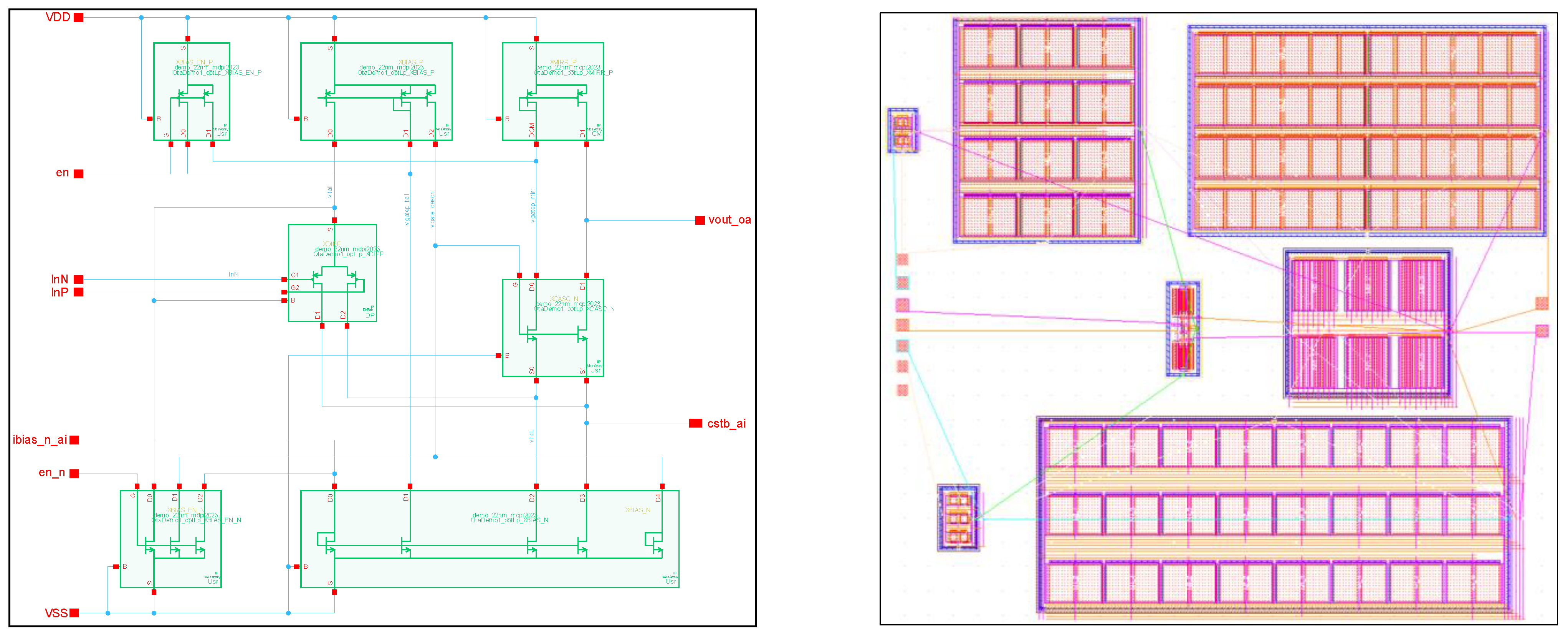
Figure 8.
Amplifier with the building blocks generated. The schematic is depicted on the left (vector graphic which is derived from the actual design view) and the initial, unconnected layout with full building block layouts is depicted on the right (manually placed according to the schematic positions). All building block layouts are automated by generators based on layout parameters that can be controlled already during schematic-level design entry.
Figure 9.
Depiction of the Generator Creator flow. The basic steps include generator-based schematic entry, automatic code creation, and automatic layout generation. During these steps, both already existing procedural building block generators and flexible templates are utilized. Based on the generated results, iterations might be required in order to adapt (sub) generator parameters.
Figure 10.
GUI of the hierarchical template-based generator (left) and the corresponding representation with illustrated hierarchy (right). Based on the hierarchical parameters for placement method (placeMethod, here the template called “street”), instance place pattern (placePattern), wire names (wire_names), and rotation pattern (rotPattern), the abstract template illustrated on the right is fully represented. Upon generation, the building blocks are generated and the predefined template controls the layout placement and routing process starting from the lower level generators including the amplifier towards the top-level generator.
Figure 11.
Generated layout examples of the HPF in a 22 nm technology based on the placement pattern given in
Section 4.3 (vector graphic exports from the actual layouts, thus slight deviations might occur). While (
a) includes the amplifier variant “LP”, (
b) instantiates the amplifier variant “Speed”. In order to get a rectangular shape, the capacitor arrangement at the bottom was generated with adapted unit device sizing.
Figure 12.
Frequency behavior of the HPF variants when using the amplifier variants “LP” and “Speed”. Each variant was simulated both on schematic level and post-layout. It can be seen that the speed variant produces less gain but achieves a higher upper corner frequency. After extraction, about 5.7 dB and about 4.3 dB gain is reduced for variant “LP” and variant “Speed”, respectively.
Table 1.
Comparison of schematic-level and post-layout simulations of the amplifier variants.
Table 1.
Comparison of schematic-level and post-layout simulations of the amplifier variants.
| | Variant | LP,
Schematic | LP,
Layout 1 | LP,
Layout 2 | Speed,
Schematic | Speed,
Layout 1 | Speed,
Layout 2 |
|---|
| Measure | |
|---|
| DC Gain (dB) | 42.15 | 42.74 | 42.55 | 34.6 | 32.89 | 32.11 |
| Deviation | | 1.40% | 0.95% | | −4.94% | −7.20% |
| 3dB BW (MHz) | 0.770 | 0.781 | 0.777 | 2.20 | 2.19 | 2.30 |
| Deviation | | 1.36% | 0.88% | | −0.45% | 4.17% |
| Phase Margin (°) | 78.56 | 75.71 | 74.45 | 83.4 | 83.17 | 83.45 |
| Deviation | | −3.63% | −5.23% | | −0.28% | 0.06% |
| DC Current (µA) | 89.5 | 92.2 | 91.5 | 253 | 248 | 259 |
| Deviation | | 2.93% | 2.16% | | −2.09% | 2.29% |
| Settling, rise (ns) | 162 | 160 | 152 | 110 | 111 | 112 |
| Deviation | | −1.54% | −6.11% | | 1.27% | 2.27% |
| Settling, fall (ns) | 123 | 144 | 152 | 106 | 110 | 110 |
| Deviation | | 16.88% | 23.13% | | 3.40% | 3.96% |
| Offset (mV) | 0.812 | 0.930 | 0.753 | 5.83 | 19.2 | 25.9 |
| Deviation | | 14.57% | −7.25% | | 228.76% | 344.29% |
Table 2.
Comparison of schematic-level and post-layout simulations of the HPF variants.
Table 2.
Comparison of schematic-level and post-layout simulations of the HPF variants.
| | Variant | HPF with Amp
LP, Schematic | HPF with Amp
LP, Layout | HPF with Amp
Speed, Schematic | HPF with Amp
Speed, Layout |
|---|
| Measure | |
|---|
| DC Current (µA) | 774.7 | 776.7 | 928.3 | 925 |
| Deviation | | 0.26% | | −0.36% |
| Input capacitance (fF) | 989 | 1025 | 1060 | 1067 |
| Deviation | | 3.68% | | 0.66% |
| PSRR @ DC (dB) | 23.35 | 20.37 | 34.31 | 34.35 |
| Deviation | | 16.88% | | 3.40% |
| PSRR @ worst case (dB) | 23.09 | 20.36 | 28.28 | 26.74 |
| Deviation | | 14.57% | | 228.76% |
Table 3.
Quantitative and qualitative comparison of the generators used.
Table 3.
Quantitative and qualitative comparison of the generators used.
| Generator | Type | Flexibility
(Selection) | Approx. Code Lines | Time to
Generator | Typical Runtime
(Xeon E5-2637v3) |
|---|
MosArray/
CapArray | Procedural; manually programmed | Transistor and Capacitor topologies; matching style & arrangements; layout details | 5500/2900 | Months
(manually) | About
5–10 s
(varies with arrays size) |
| ResArray | Procedural; manually programmed | Resistor series and parallel circuits; routing width | 1950 | Weeks
(manually) | About
15 s |
| Amplifier | Template-based procedural;
automatically created | Hierarchical block generation incl. sub generator parameters; P&R pattern | 4800 | Seconds
(this work:
automatically) | About
40 s |
| HPF | Template-based procedural;
automatically created | Hierarchical block generation incl. sub generator parameters; P&R pattern | 5700 | Seconds
(this work:
automatically) | About
120 s |
| Disclaimer/Publisher’s Note: The statements, opinions and data contained in all publications are solely those of the individual author(s) and contributor(s) and not of MDPI and/or the editor(s). MDPI and/or the editor(s) disclaim responsibility for any injury to people or property resulting from any ideas, methods, instructions or products referred to in the content. |
© 2023 by the authors. Licensee MDPI, Basel, Switzerland. This article is an open access article distributed under the terms and conditions of the Creative Commons Attribution (CC BY) license (https://creativecommons.org/licenses/by/4.0/).


