Article

Development of a Handheld Optical Fusion Splicer with a Wing Sleeve Optical Connector

1
Soltech Infonet Co., Ltd., Seoul 07217, Republic of Korea
2
Tech University of Korea, Siheung-si 15073, Republic of Korea
*
Author to whom correspondence should be addressed.
Electronics 2023, 12(22), 4629; https://doi.org/10.3390/electronics12224629
Submission received: 14 September 2023 / Revised: 8 November 2023 / Accepted: 9 November 2023 / Published: 12 November 2023

Abstract

:
FTTH (Fibre to the Home) uses a fusion splice field-assembled optical connector. The fusion splice field-assembled optical connector is connected and assembled using a generic fibre fusion splicer. However, general purpose fusion splicers make the device difficult to operate in the installation field because the fusion splicer is too large and heavy to handle. As a result, the fibre optic splice often breaks during the optical connector assembly process. This makes it difficult to apply fusion-spliced optical connectors in the FTTH field. To solve this problem, this paper proposes a fusion splicer for FTTH that can perform fusion splicing using a wing-type sleeve optical connector. The proposed fusion splicer, with a connection module with a lifting/lowering function, is implemented to connect and protect the wing-type sleeve field-assembled optical connector. In addition, by eliminating the tube heater used as a connection protection method in the existing fusion splicer, the power module is reduced. The developed fusion splicer was evaluated for assembly reliability through splice loss measurements and a comparison of assembling time with the existing fusion splicer.

1. Introduction

In Korea, high-speed Internet service with a speed of 100 Mbps has become universal, with a penetration rate of 100% by 2020. Currently, 10 Gbps speed services are becoming increasingly popular and have become the basis for the development of various online content. Internet service providers provide a high-speed Internet service by using a FTTH (Fibre to the Home) service, which has a high degree of service quality improvement and an excellent cost reduction effect [1,2]. FTTH service is a service that connects the OLT (Optical line terminal) and ONT (Optical network terminal) using an optical fibre. The OLT is located in an ISP’s central office to collect subscribers, while the ONT is an Internet terminal located in the subscriber’s home [3]. The quality of the FTTH service depends on the quality of the optical fibre that makes up the line, with the quality of the branching/combining of the optical fibre and the quality of the termination of the optical fibre that enters the subscriber’s premises being particularly important. Internet service providers have used matching gel-type field-assembled optical connectors for their convenience in terminating incoming optical cables, but they are also expanding the use of fusion-type field-assembled optical connectors to improve line quality [4].
The field-assembled fusion splicing optical connector is a permanent fusion splicing method used between the optical connector and the incoming optical cable to handle the termination of the incoming optical cable in FTTH. It is currently being used more widely, targeting subscribers or sites where quality is a priority. However, despite the advantages of reliability and continuous use of fusion splicing, its utility is still limited by the price burden of expensive fusion connectors combined with the inconvenience of using a large and heavy fusion splicer at FTTH sites, as well as splice point breakage when using heat shrink tubing to protect the splice point.
To solve this problem, this paper proposes a fusion-spliced optical connector without shrink tubing [5] and a fusion splicer with reduced size and cost by eliminating a heating tube module. In this paper, a fusion splicing field-assembled optical connector, which protects the splice point with wing sleeves on the optical connector head instead of a tube heater, and a fusion splicer with an elevating/lowering function, are developed for the fusion splicing field-assembled optical connector. The developed fusion splicer eliminates the tube heater used in the existing fusion splicer [6,7] and minimizes the power module, which allows it to be hung around one’s neck without a stand, making it possible to work with both hands. In order to analyse the performance and characteristics of the developed optical connector and fusion splicer, the splicing performance and assembly times were measured.
This paper is organised as follows. Section 2 identifies the problems of the existing field-assembled optical connector and the limitations of the fusion splicer, and Section 3 presents a new type of fusion splicer and connector designed to solve these problems. Section 4 evaluates the performance of the developed fusion splicer through experimental measurements and Section 5 concludes the study.

2. Fusion Slicing of Optical Connectors

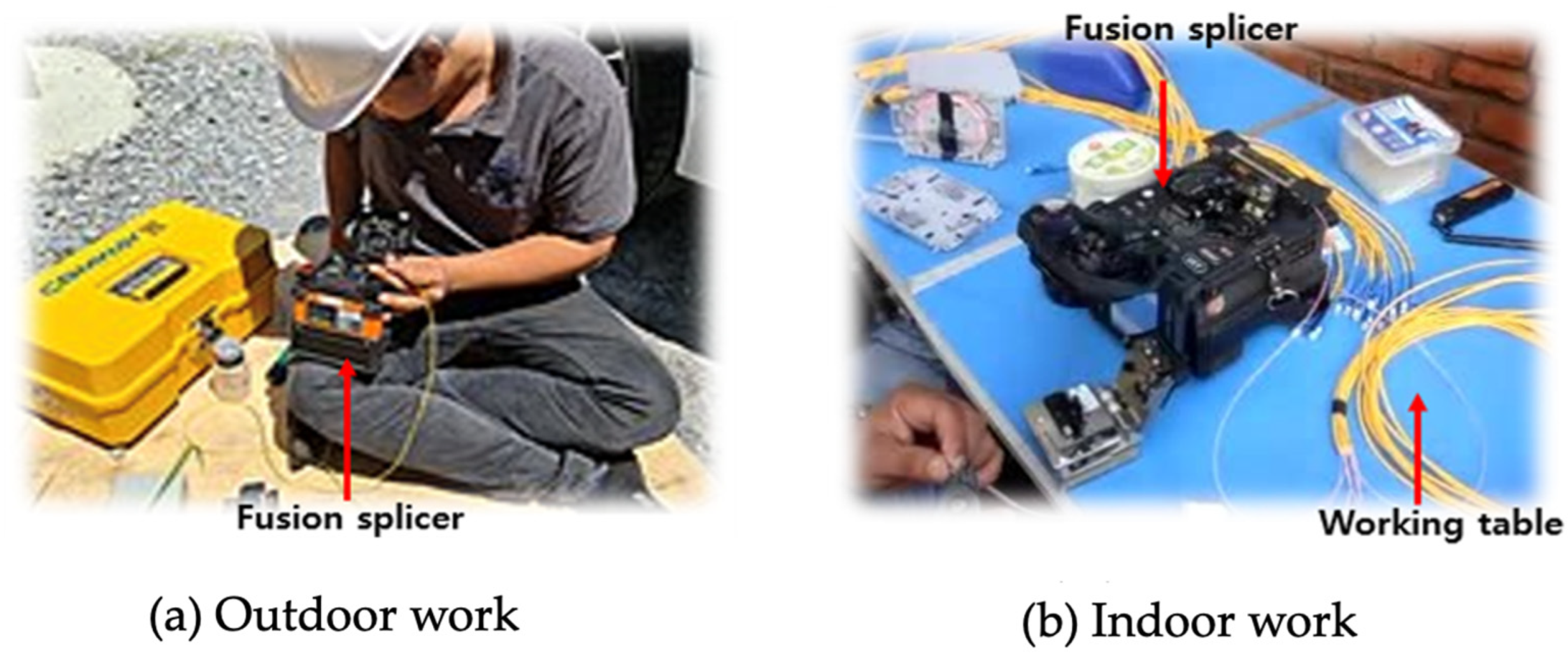
2.1. Difficulties in Fusion Splicing

The fusion splicing method of field-assembled optical connectors uses a fusion splicer for splicing. Since the existing fusion splicer is designed for the fusion splicing of general optical fibre cables, there are several problems that arise in the fusion splicing of field-assembled optical connectors. As the equipment is bulky and heavy, it is necessary to prepare a separate work space, as shown in Figure 1, along with additional facilities such as a work table for on-site use [8]. However, at multiple installation sites, such as the subscriber’s premises, rooftop, and outside wall, it is difficult to configure and use separate workspaces due to the cramped and unstable FTTH installation environment.
In particular, it is impossible to use a universal fusion splicer in the case of pole installation. Installations in several different types of sites require the use of an elevated work vehicle, or doing as much work as possible on the ground and then moving it to the pole. This process is very inconvenient for ISPs (Internet Service Providers) who need fast connections or who need to maintain the Internet in a residential area [9].
Second, the general fusion splicer uses a heat tube method to shrink the tube to protect the splice point after fusion splicing the optical fibre [10]. This method does not cause any problems when splicing thin fibre optic cables, but when fusion splicing an optical connector head of a short optical fibre [11], as shown in Figure 2, several problems may occur during the splice protection process.
In the optical connector fusion splicing process, the prepared optical connector head and optical cable are mounted on the horizontal axis movement module of the fusion splicer, and after alignment, the aligned optical fibres are fusion spliced using high voltage discharge. A tube is wrapped around the fusion splice point for protection and the cable is manually moved to the heater to heat-shrink the tube to protect the splice point [12]. During this process, any slight bending or distortion of the optical fibre will occur in the optical fibre and the impact will be concentrated at the splice point, which can often cause the splice point to break. Figure 3 shows the transfer of the cable and fusion-spliced optical connector head from the splice module to the sleeve heater [13]. These two problems increase the failure rate of the fusion-spliced optical connector increases in FTTH.

2.2. Related Works

Fusion-spliced field-assembled-type optical connectors and fusion splicer manufacturers have proposed ways to solve the mentioned problems. A miniaturised fusion splicer has been manufactured and released by reducing the size and weight to increase the ease of field assembly [14]. However, since the optical connector connection method and the splice point protection method rely on the existing optical fibre connection method, there is a limit to the miniaturisation that can be achieved.
Several methods have been proposed for the design of a fusion-type field-assembled optical connector: Firstly, bending is prevented by minimising the thickness and weight of the optical connector head, and the connected optical connector can be moved to the heater using an auxiliary device to prevent bending.
Secondly, a method without the use of tube heating to protect the splice point has been proposed. Instead of using a heat shrink tubing, a protective sleeve with double-sided tape is attached to the optical connector head to protect the splice point; this is the best method in terms of safety against bending, as it is not necessary to move the fusion-spliced optical fibre. Figure 4 shows the fusion-spliced optical connector head with a double-sided table-type protective sleeve attached in the form of a wing [15].
However, the existing products described here only provide a sleeve to connect and protect a thin 0.25 mm or 0.9 mm diameter fibre optic cable and do not provide a solution for direct connection to an optical drop cable used for FTTH. In addition, as the existing fusion splicers do not have the capability to fusion-splice a connector with a wing-mounted protective sleeve, such an optical connection solution cannot be used at the FTTH installation site. The existing fusion splicer is designed as a fibre-to-fibre splicing device, and only the protection method of the heater tube is provided.
To solve this problem, this paper has developed an optical connector equipped with a wing sleeve that can be directly connected to the optical cable using a fusion splicer that can connect the optical cable and the connector. The developed fusion splicer also implements a space-saving function by raising and lowering the splice module to protect the splice module by folding the sleeve at the fusion splice point, without requiring a process of moving the optical connector to the heater for tube heating after fusion splicing. The size and weight have also been minimised by simplifying the power supply by eliminating the shrink tube heater.

3. Design of Optical Connector and Fusion Splicer

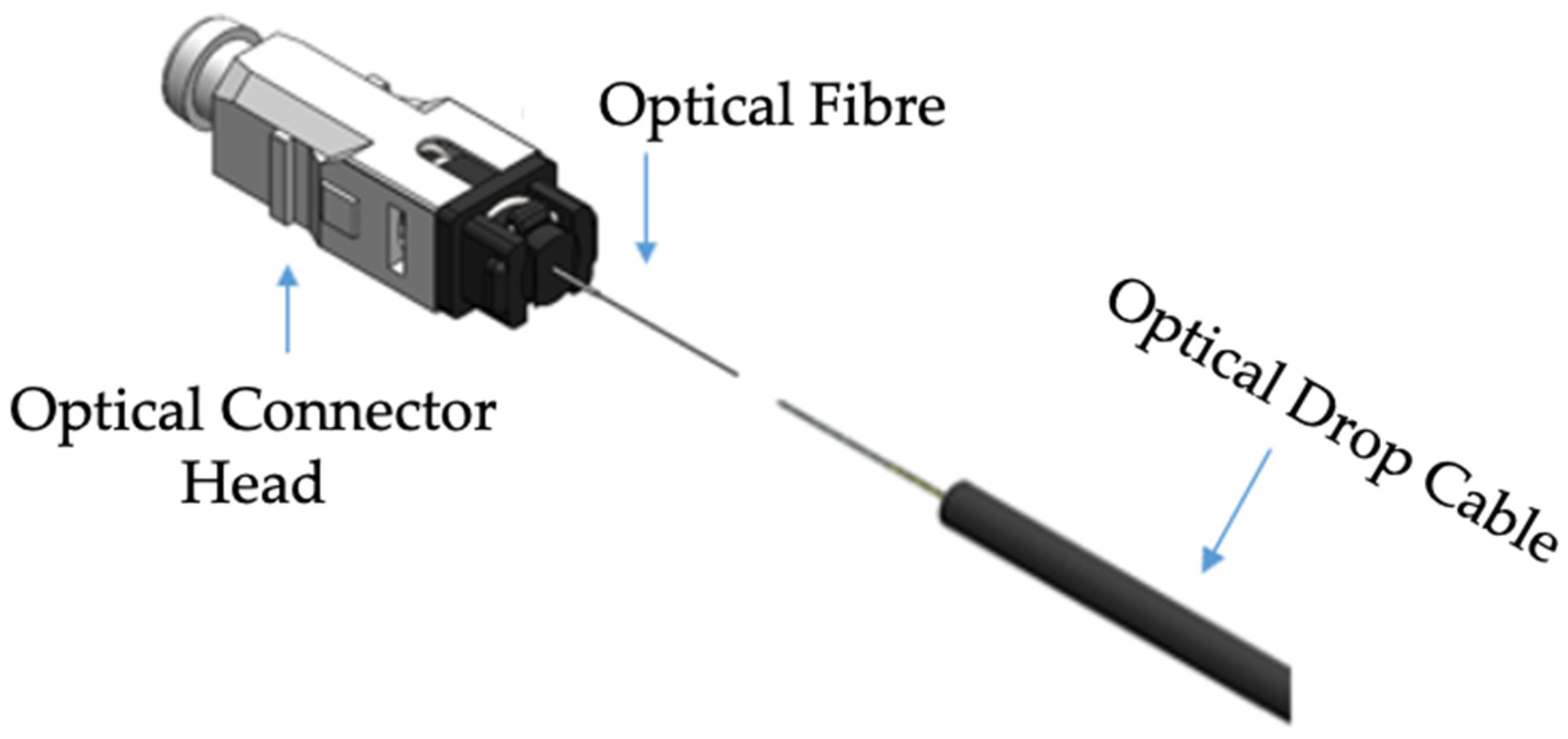
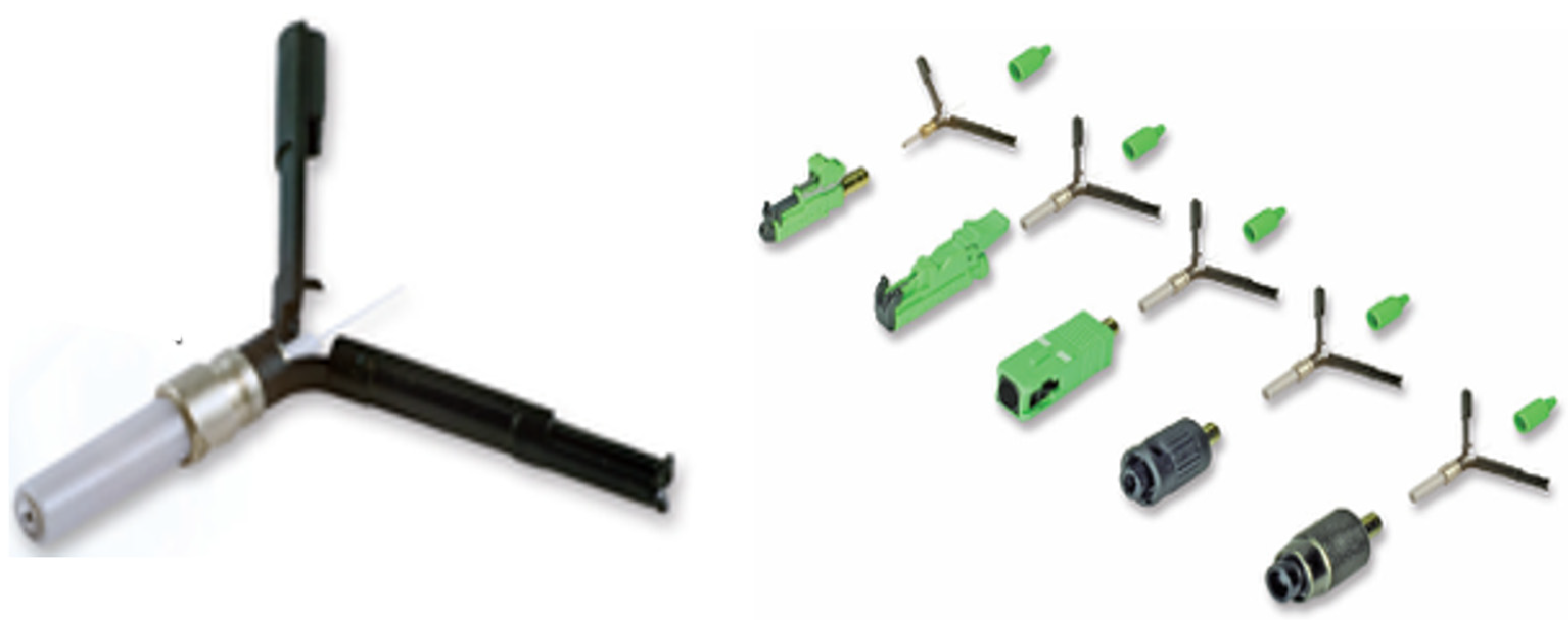
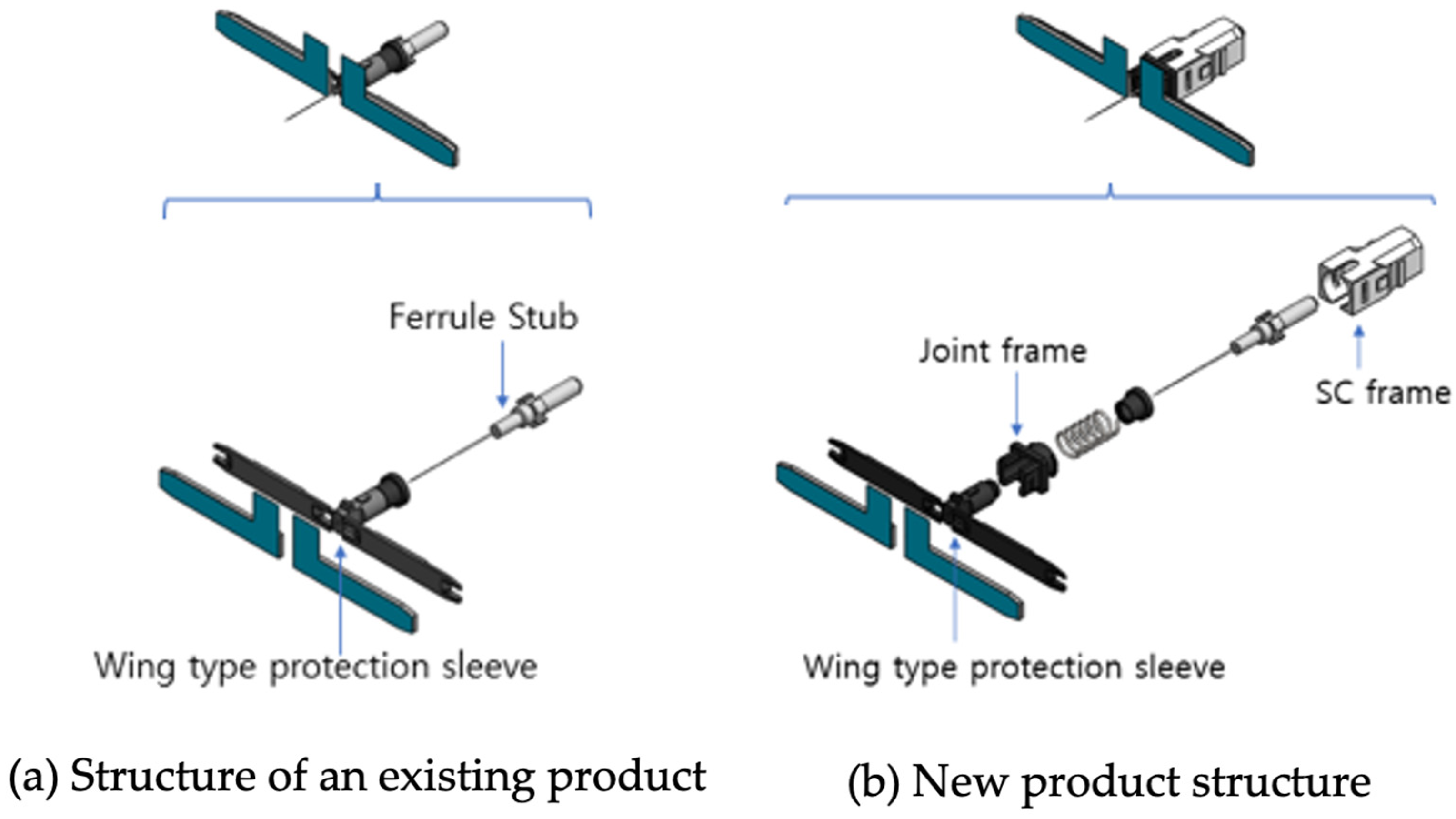
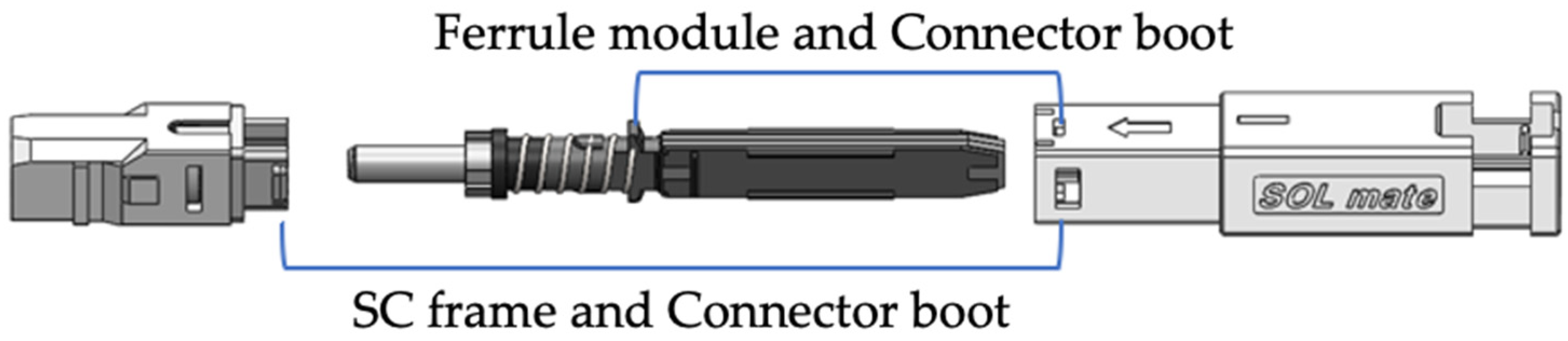
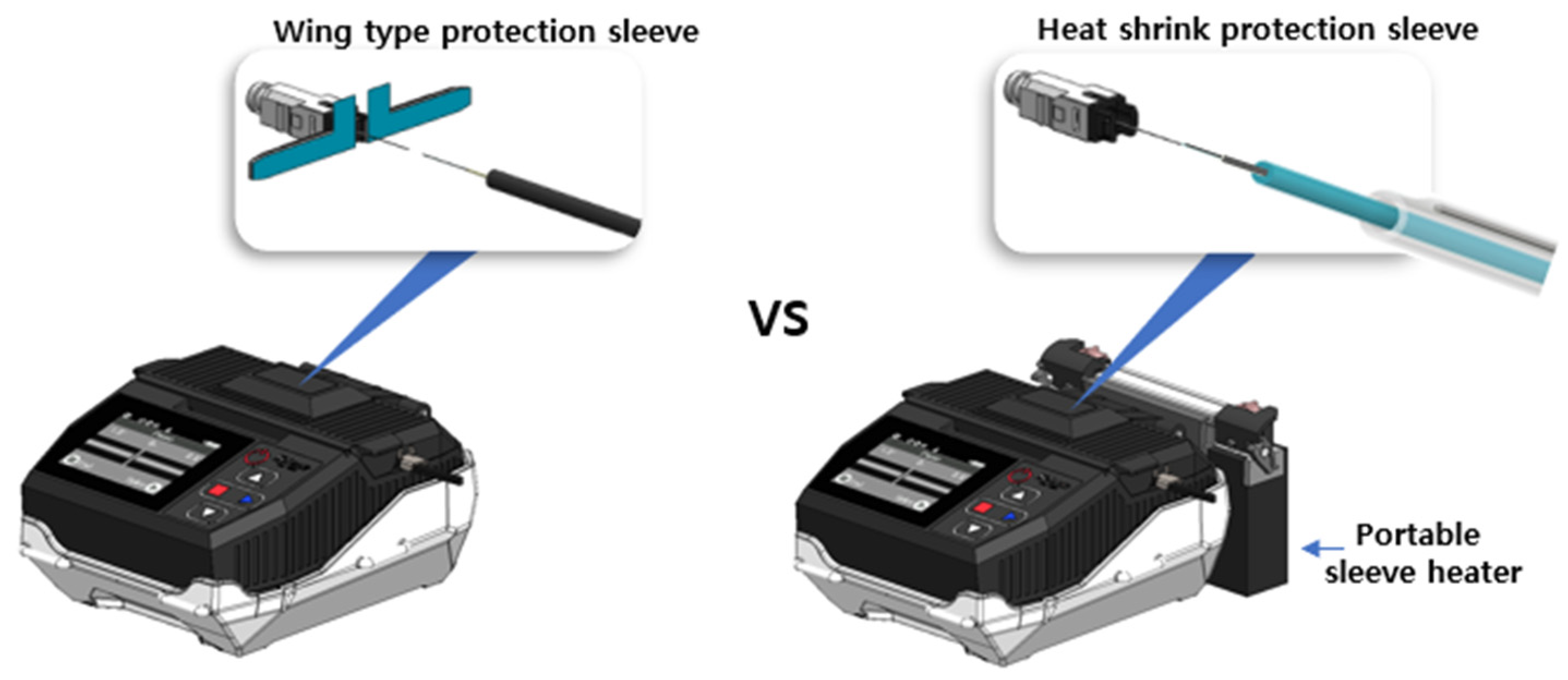
3.1. Design of Optical Connector Dedicated to Field Assembly

To protect the splice point without the use of heat shrink tubing, a protective sleeve with double-sided adhesive tape is attached to the ferrule [16] module. In addition, a joint frame and an SC frame (shell) [17] are combined with a ferrule module with a wing sleeve to form a complete optical connector head. The joint frame is designed to be combined with the cable boot. Figure 5 shows the configuration diagram of the fusion-spliced wing-type ferrule optical connector head between an existing product (a) and our new design (b).
Next, after fusion splicing the optical connector head and the optical drop cable [18], a cable boot is designed to strongly stabilise the optical connector head and the jacket of the optical drop cable. The designed cable boot directly connects the frame of the connector head to the jacket of the optical drop cable. The cable boot pushes the wing type protection sleeve inwards to strengthen the adhesive force of the tape, and it also protects the optical fibre inside the optical connector from the external pulling force generated by the optical drop cable. The connection method of the optical connector head and the cable boot is designed to have a double connection structure that separates the frame connection and the ferrule module connection, so that the bending of the optical fibre caused by the ferrule pressure generated during the connection of the optical connector can pass through the cable. Figure 6 shows the double joint structure of the developed optical connector head and cable ferrule.

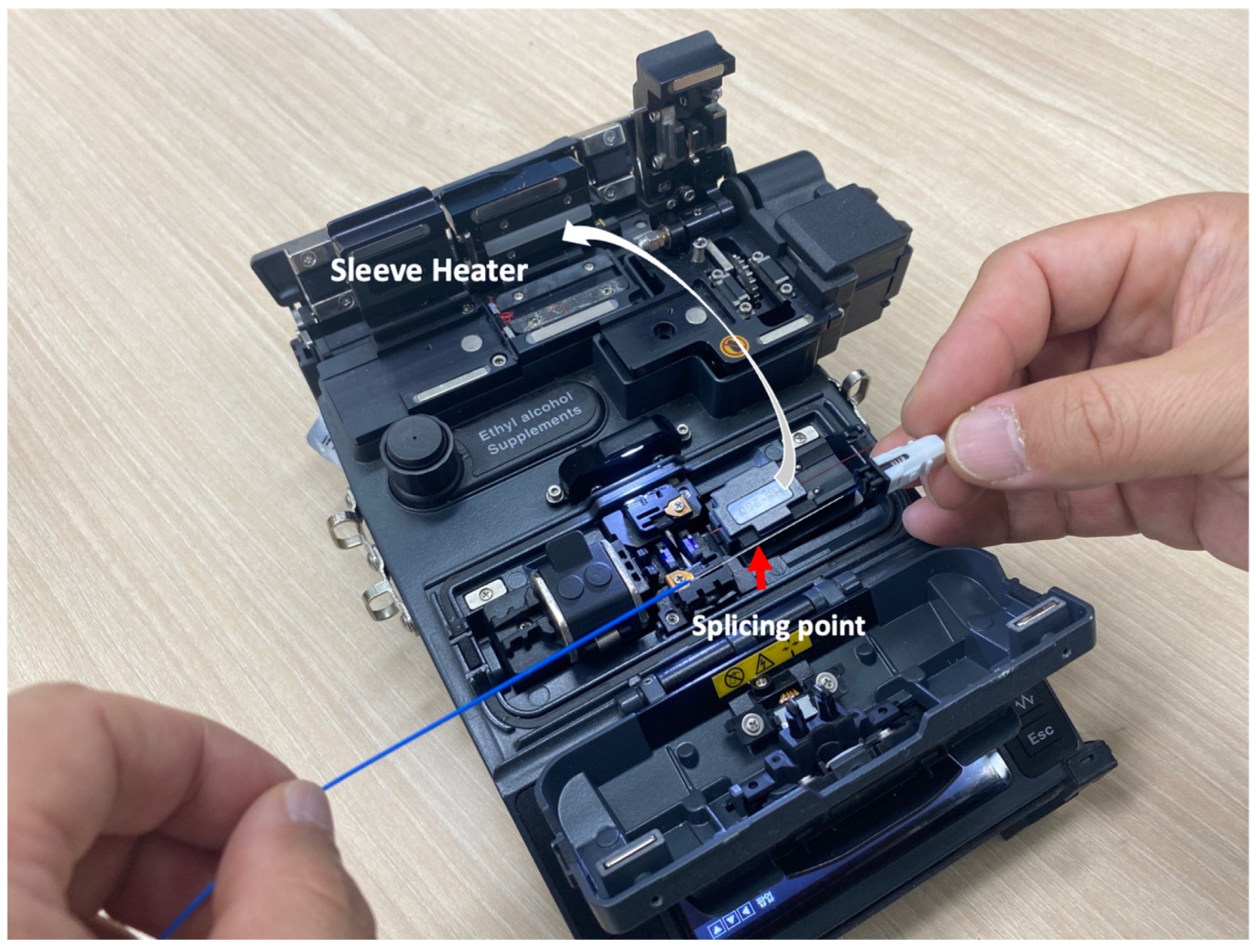
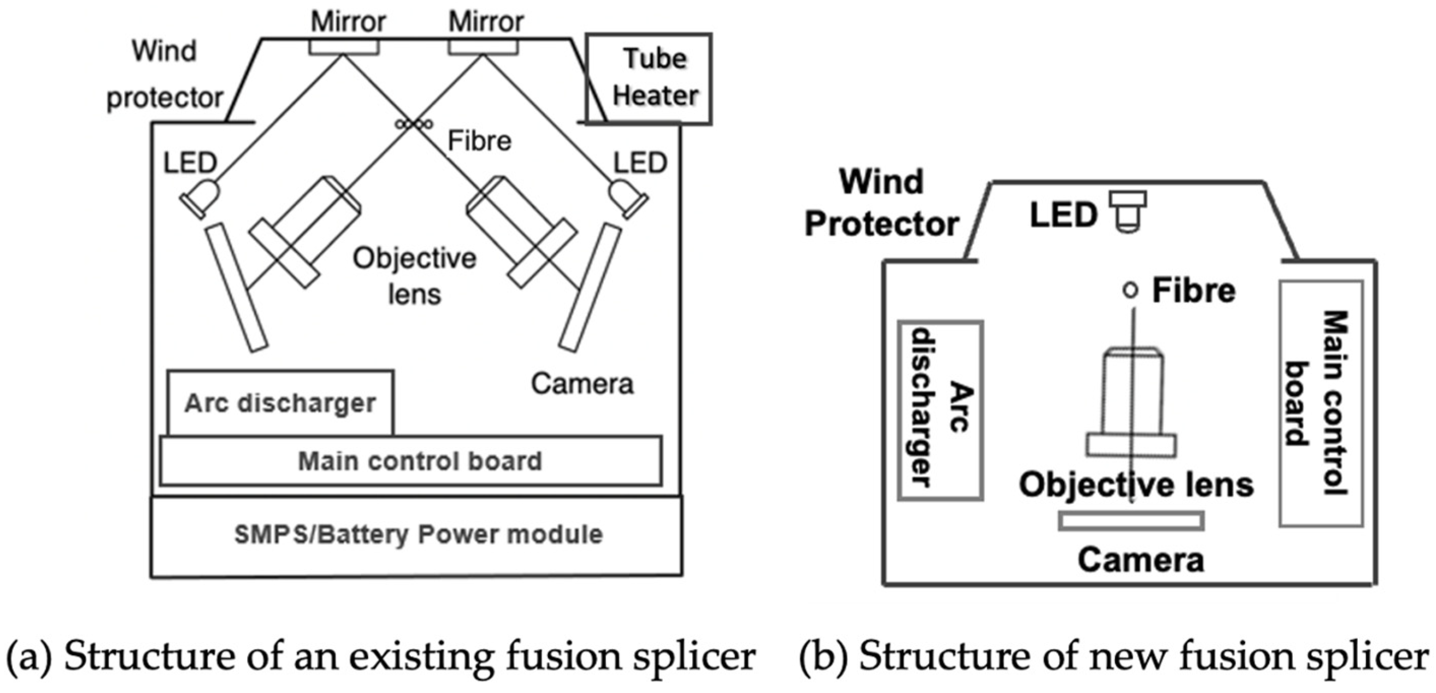
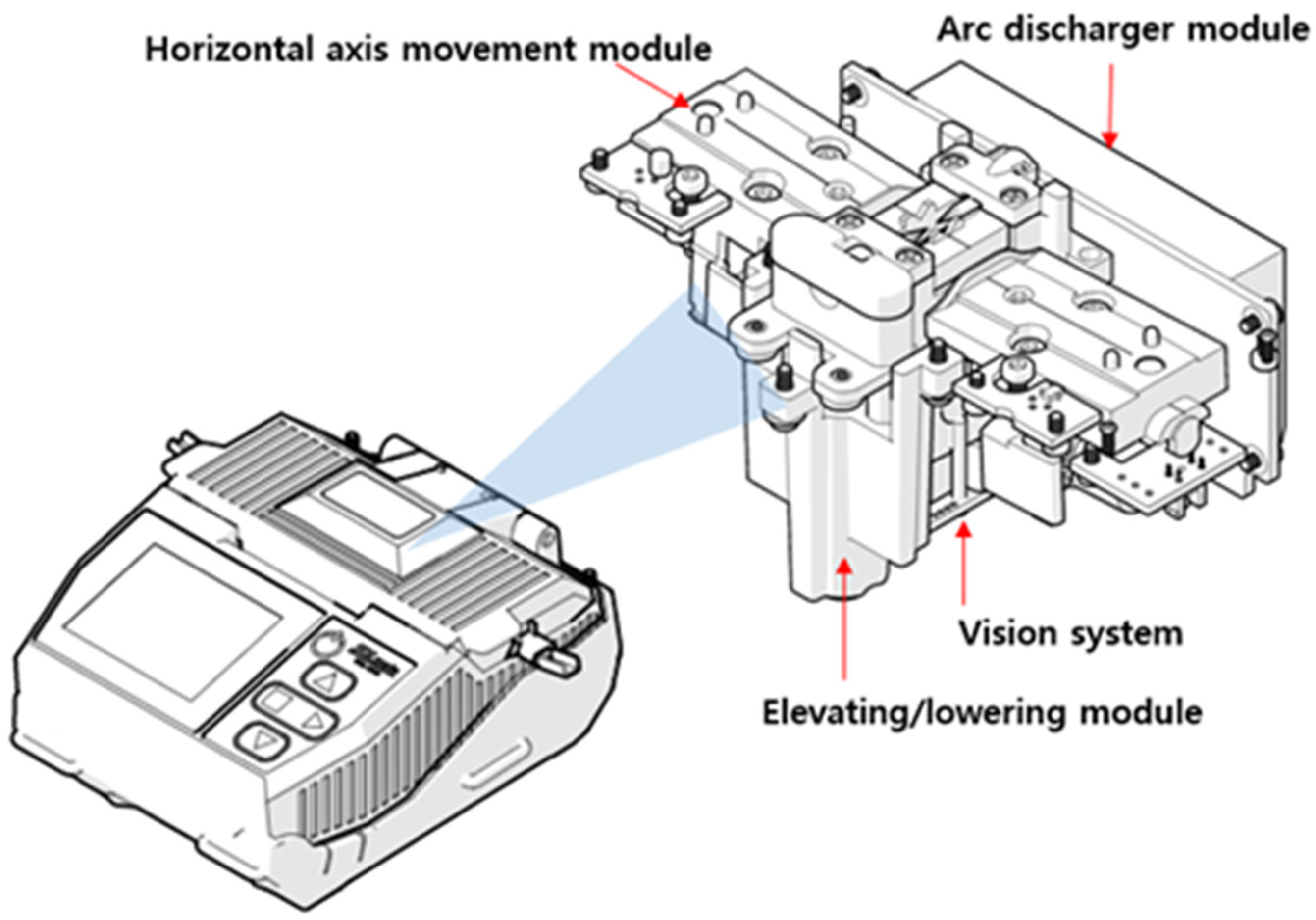
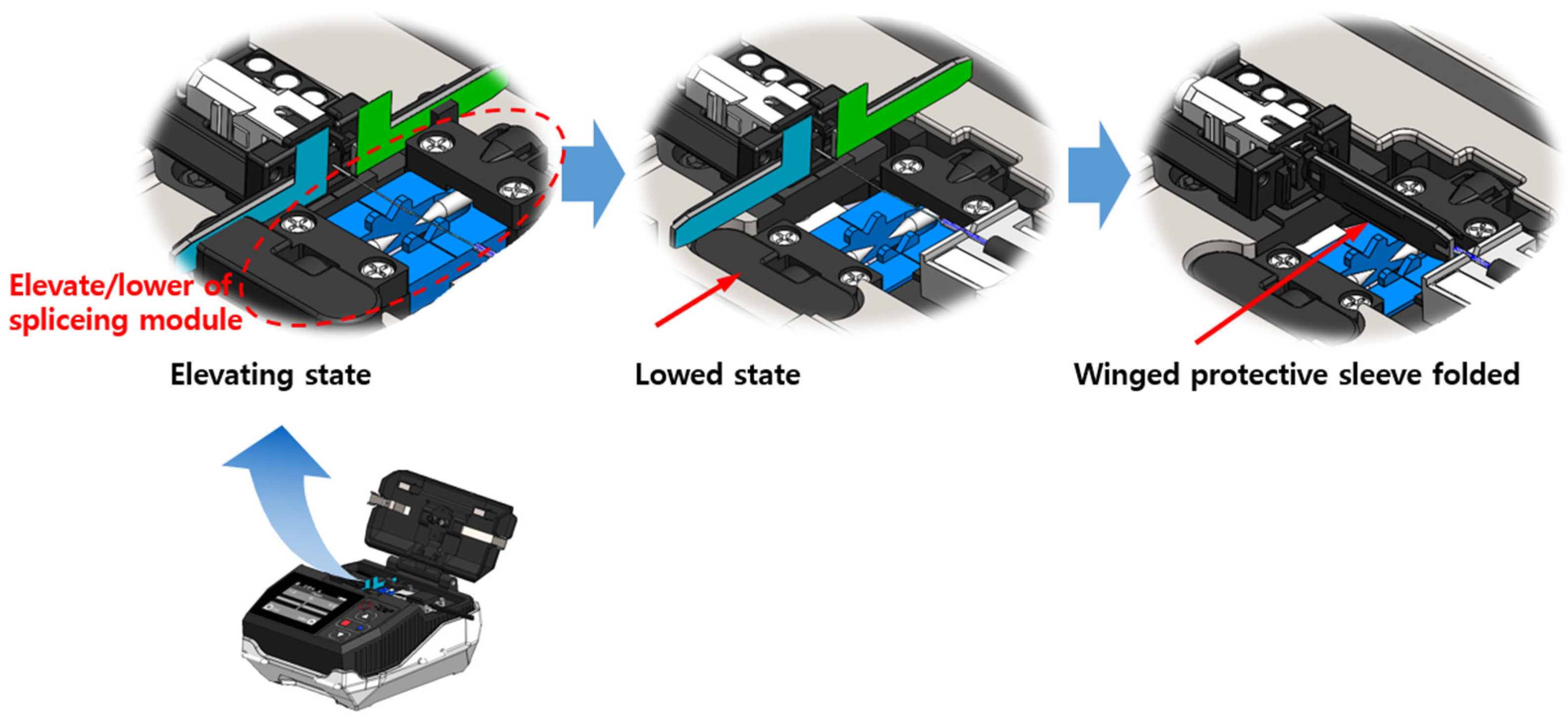
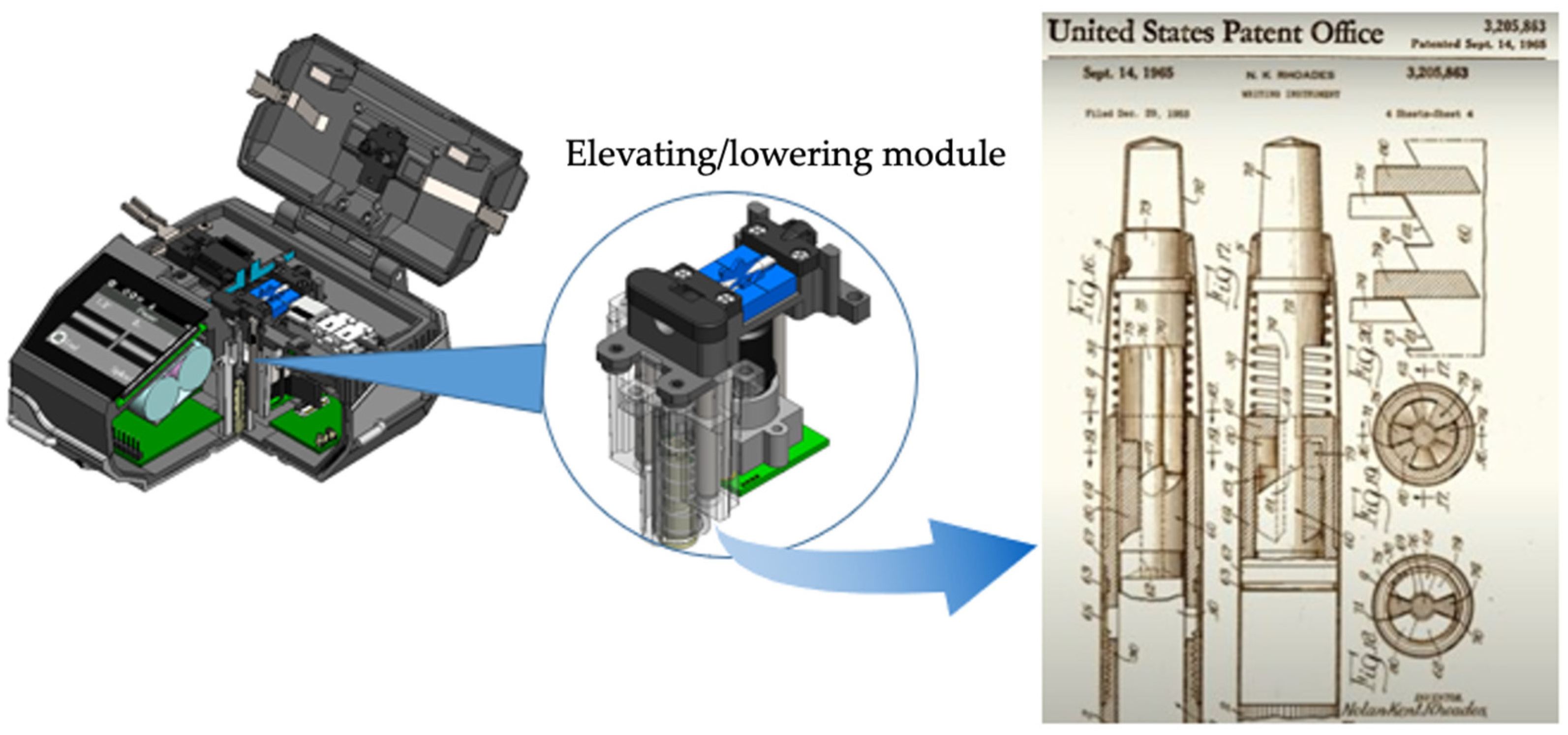
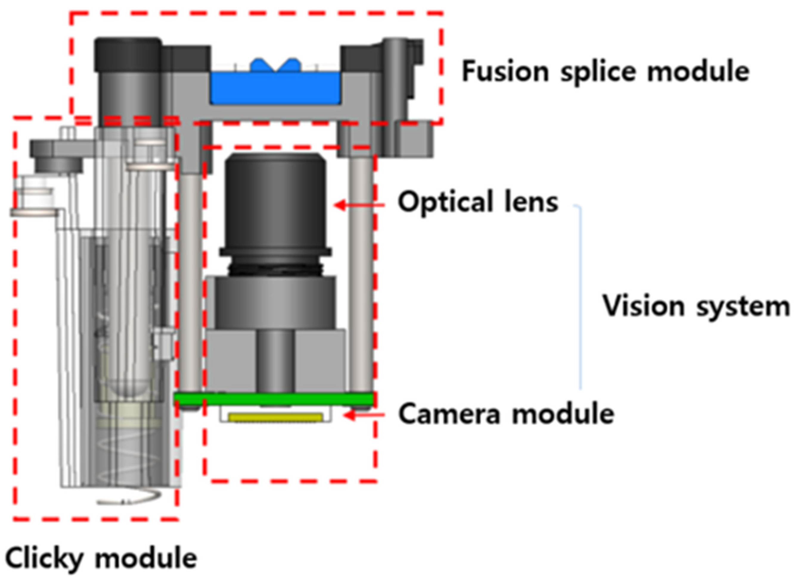
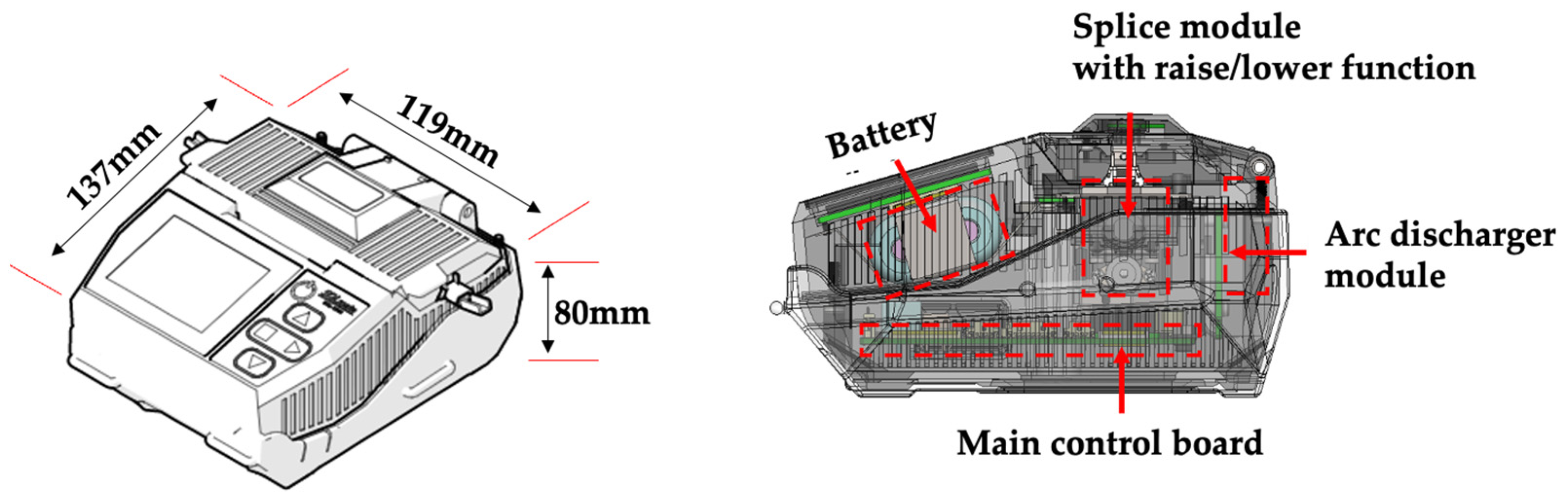
3.2. Design of a Fusion Splicer for Field Assembly of Optical Connectors

The optical connector developed as described above can protect the splice point immediately after splicing, eliminating the process of moving the optical connector head to the heater to protect the splice point. To achieve this, a lift/lower function for the fusion splice module is developed to allow the wing sleeve to be folded into the splice module. As shown in Figure 7b, the size and weight are reduced by using only one camera module, and the power module required for heating has been removed together with the heater, as the fusion splicer developed does not use a tube heater, as shown in Figure 7a. The one camera module has image processing from the top view by means of edge detection and end face angle detection.
As shown in Figure 8, the developed fusion splicer consists of an arc discharge module that generates heat by high voltage electrode discharge [19], a horizontal axis movement module for transporting the optical connector head and fibre optic cable, and a vision system used to align the optical fibres in conjunction with the horizontal axis movement.
The lift/lower function of the fusion splice module is designed to allow the splice module to be lowered after fusion splicing to create the space required to fold the wing-type protective sleeve. When fusion splicing is complete, the splice module is lowered by pressing the lift/lower button with a finger and stopped using the stop button. This creates a space at the top of the splice module to allow the wing sleeve to be folded. Once the wing sleeve has been folded and the optical connector and fibre holder removed, the optical connector assembly is complete.
In Figure 9, the first picture shows the splice module in the raised position, the second shows it in the lowered position and the third shows it with the wing sleeve folded in the lowered position. When the lift/lower button on the splice module is pressed hard, the splice module is lowered by the pressure and stabilised by the stop button, and when the button is pressed again hard, the stop button is released and the splice module is lifted by the elasticity of the spring. The core principle is applied in a similar way to the click of a ballpoint pen, as shown in Figure 9.
Figure 10 shows the structure and application of the click key. The click key principle consists of a cam cylinder that serves as a housing for the cam as a cam body, and the cam body rotates at a certain angle each time the key is pressed, stops in a downward state, and rotates again at a certain angle when the key is pressed again to release the cam body [20].
The lift/lower splice module consists of the V-groove/electrode module, the click module, and the vision system, as shown in Figure 11. These three modules are the most important factors in the acquisition of the high voltage discharge, alignment, and image processing information required for fibre splicing; care must be taken to ensure that these three key factors are not shaken or mechanically distorted.
Finally, the lift/lower module integrates the connector module and the vision system to be mounted in the same frame; therefore, when the connector module is lifted/lowered, the vision system also moves up and down. The vision system consists of an optical lens and camera sensor to photograph the optical fibres and transmit images to the main control board to enable motion control through image processing.
The weight of the fusion splicer developed in this paper is 680 g and its size is 119 (W) × 137 (D) × 80 (H). The fusion splicer is designed to be small enough to be held with one hand. As the splice point is protected by folding the sleeves of the splice module, the heater used in the general fusion splicer could be removed, and the overall size could also be significantly reduced by removing the AC power module. Table 1 shows the comparison of physical specifications between existing products and ours. The existing products require an additional heater tube and cable movement to protect the splice point by using the heater tube.
Figure 12 shows the external features and internal structure of the finished fusion splicer. The interior consists of a lift/lower splice module (including a splice module and a vision module), a discharge module, a main control board, and a battery. The power module is integrated into the main control board and is charged using a micro five-pin mobile phone charger. Overall, the size and volume has been significantly reduced by removing the heater, removing the AC power supply, and using a single vision system.

4. Performance Test Experiments

Experiments were conducted to confirm the performance and ease of assembly of the developed optical connector and fusion splicer. The experiments were divided into three categories: The first category was to verify the performance of the developed fusion splicer. Fusion splice loss and splice time were measured. The second category was to verify the performance of the assembled fusion-spliced optical connector. In this category, the performance of the connector was confirmed by measuring the optical performance and verifying the loss change with temperature change. The third category was to confirm the convenience and reliability of the developed fusion-spliced optical connector and fusion splicer compared to other products.

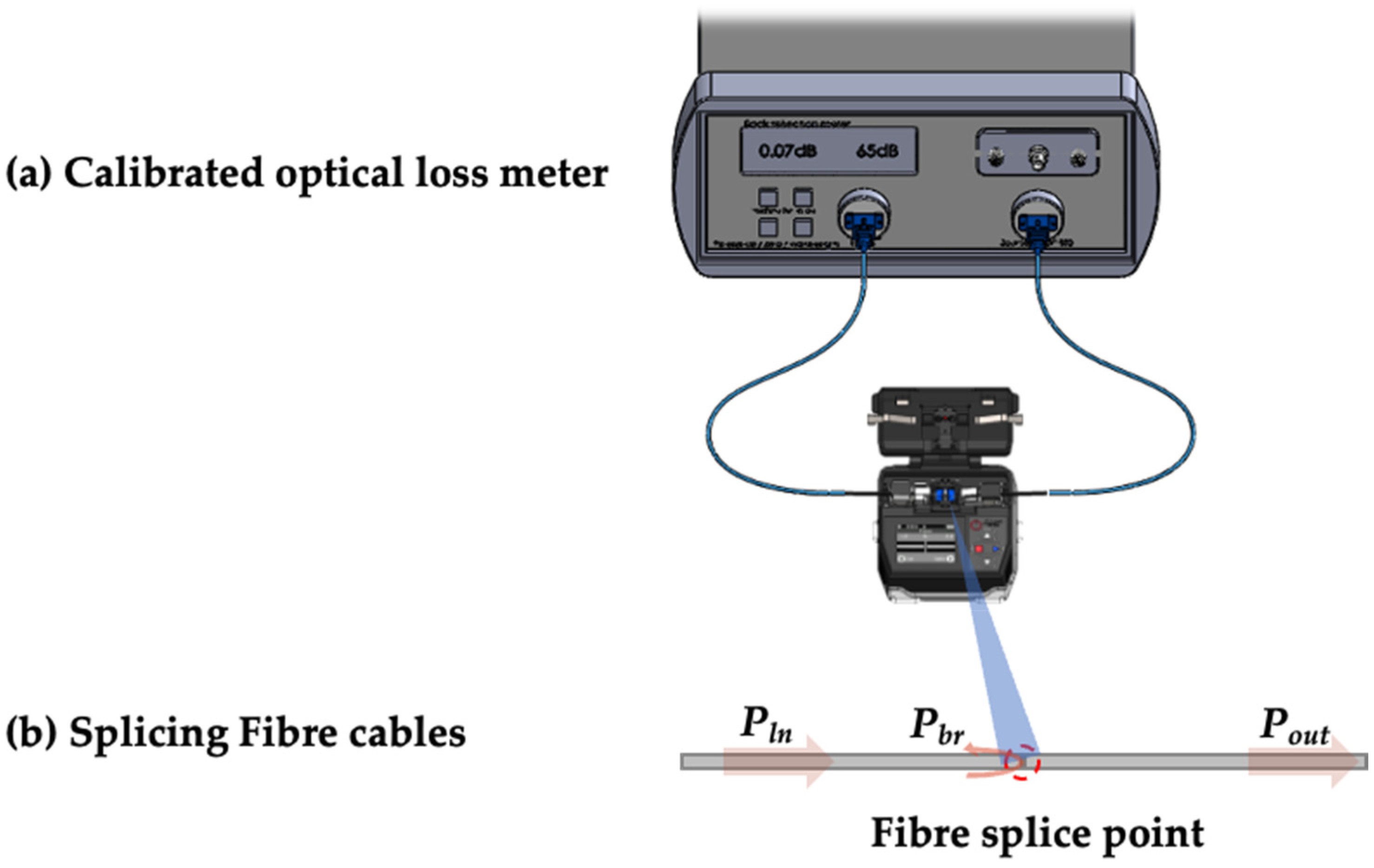
4.1. Fusion Splicer Performance

4.1.1. Experimental Procedure

As a first experiment to investigate the splicing performance of the fusion splicer, the splice point’s insertion loss and return loss were evaluated by connecting the optical fibre and the optical fibre. A calibrated optical loss meter [21] was used for this experiment. As shown in the Figure 13, the light source to be measured was initialised using the optical patch cord for the measurement. Then, after cutting the optical patch cord, it was fusion-spliced using the fusion splicer developed in this paper. The measured values are recorded by the meter.

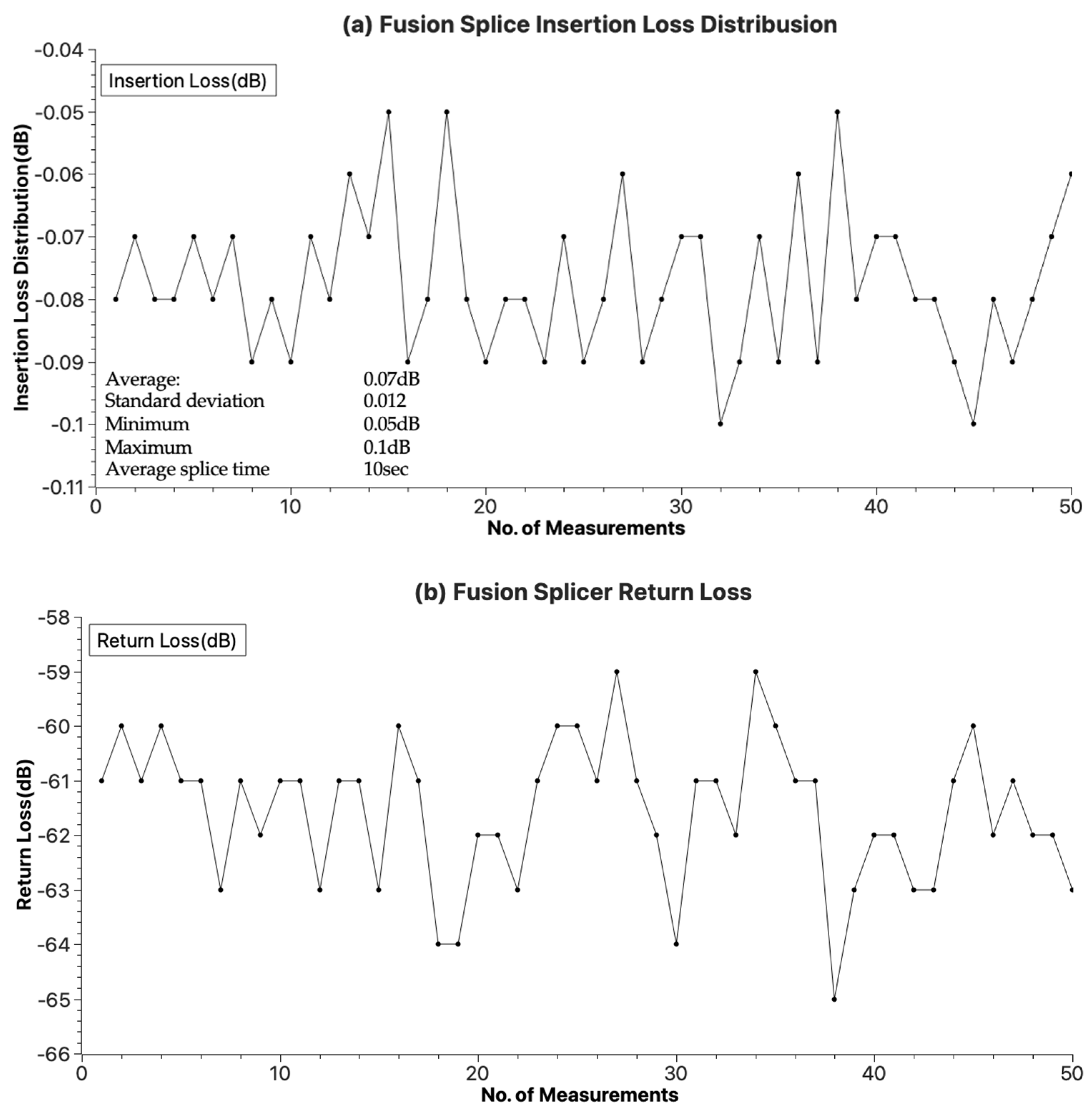
4.1.2. Result of the Experiment

The conditions and characteristics of fibre optic connectors greatly affect the performance of an installed fibre optic link. High connector loss (e.g., insertion loss), low return loss or high reflectivity will affect the ability of an application to run on a network. High return loss is a good thing and usually results in low insertion loss. Optical loss (for connectors) is simply the reduction in optical power caused by transmission through a medium such as a pair of fibre optic connectors. Return loss is the amount of light reflected from a single discontinuity in an optical fibre link such as a connector pair. Return loss is also called reflectivity. In this paper, insertion loss and return loss were measured to test the fusion splicer performance.
Figure 14 shows the splice loss distribution of the fusion splicer developed in this paper as measured in the first experiment. The insertion loss caused by fusion splicing is mostly distributed around −0.07 dB and it can be seen that the return loss is within −60 dB. With a standard deviation of 0.012, it can be confirmed that the splice loss is stable for all samples. The Korea Telecommunication Corporation Association, which consists of Korean Internet Service Providers (ISPs), has established and applied Internet FTTH facility standards [22] with the aim of maintaining communication standards and quality between operators. The facility standards include FTTH and home networks, which cover fibre-to-the-premises networks. The insertion loss required for the fusion splice point in the facility standard is within −0.1 dB, and the experimental results meet the standards required by the association.

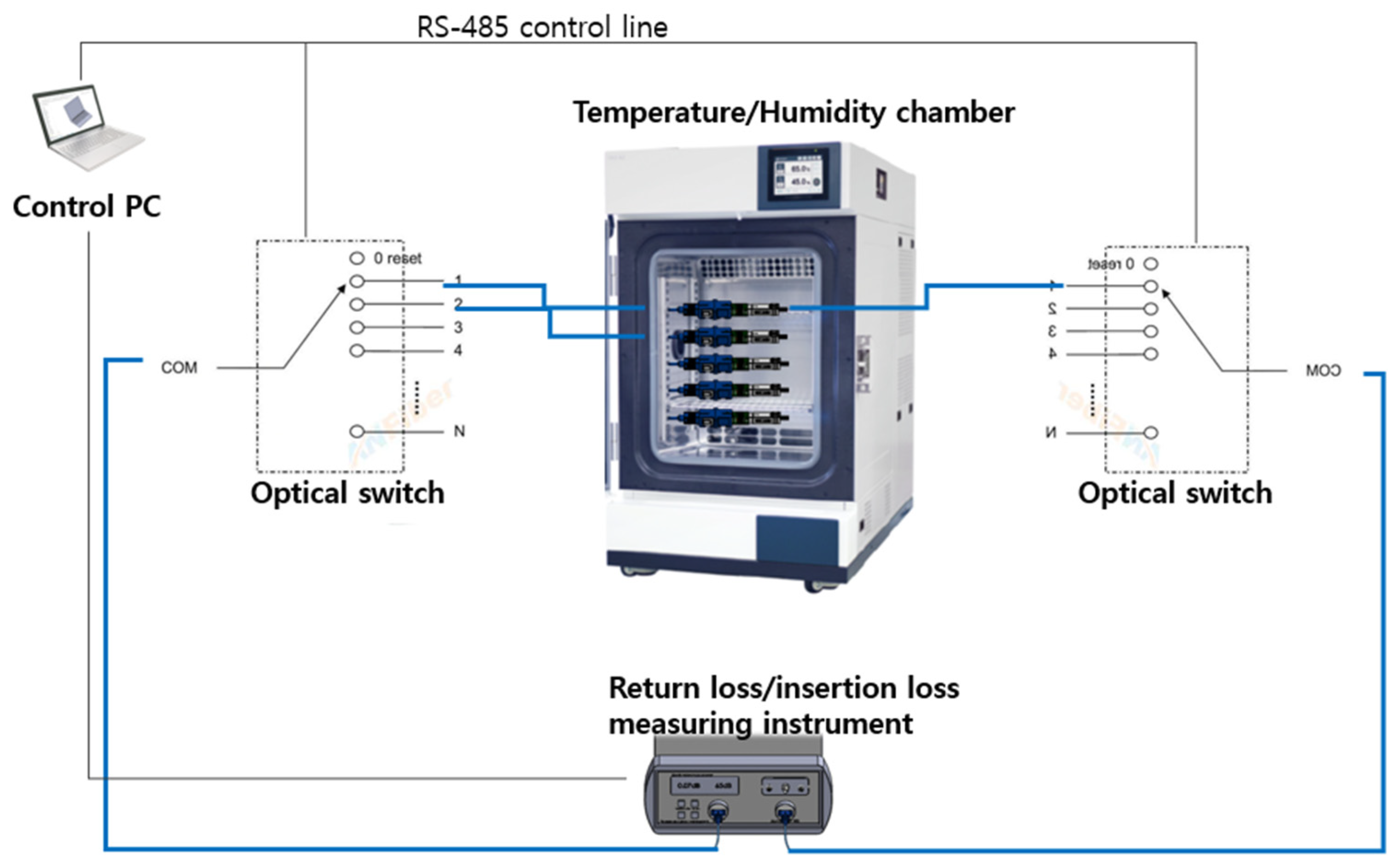
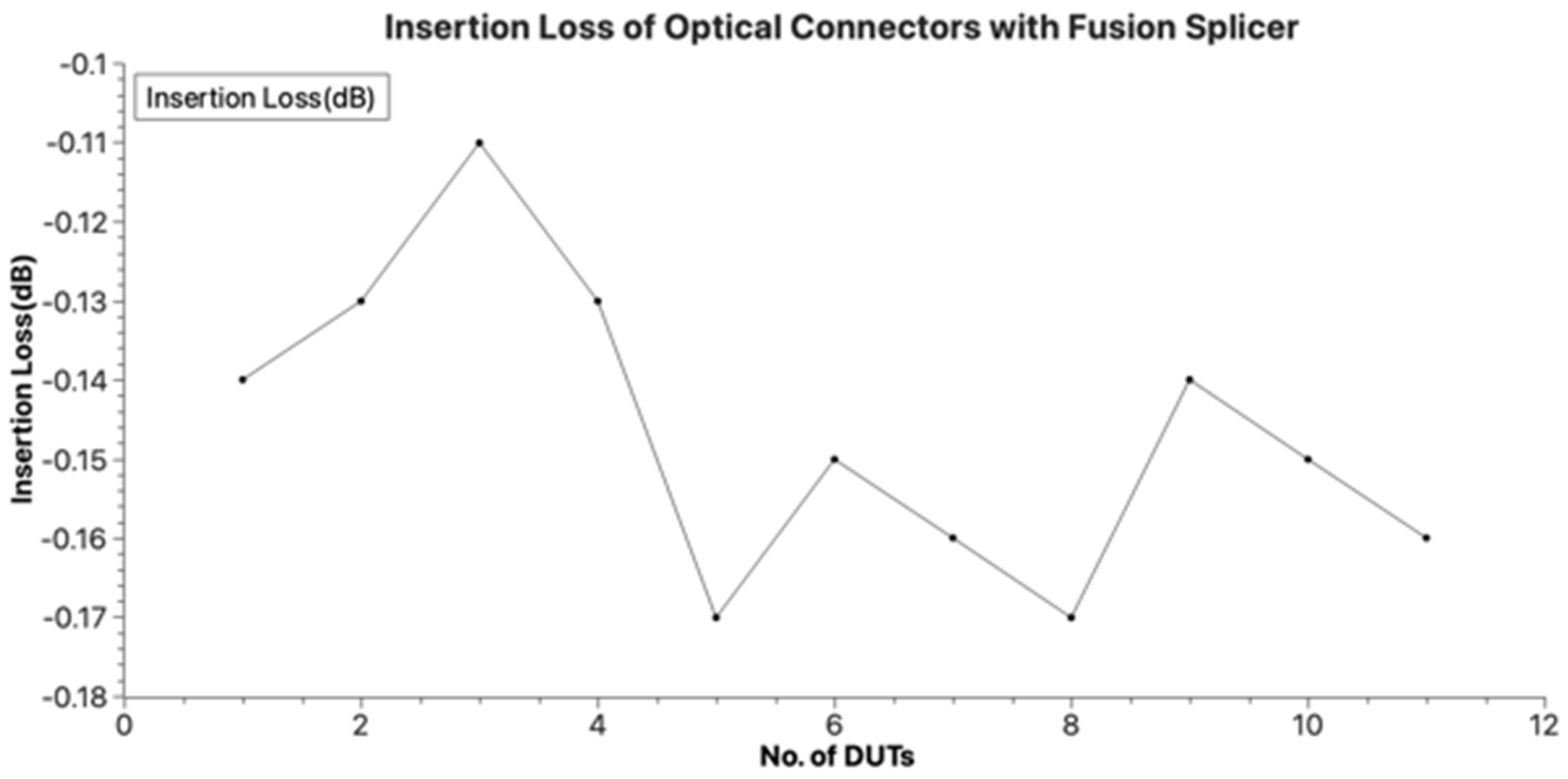
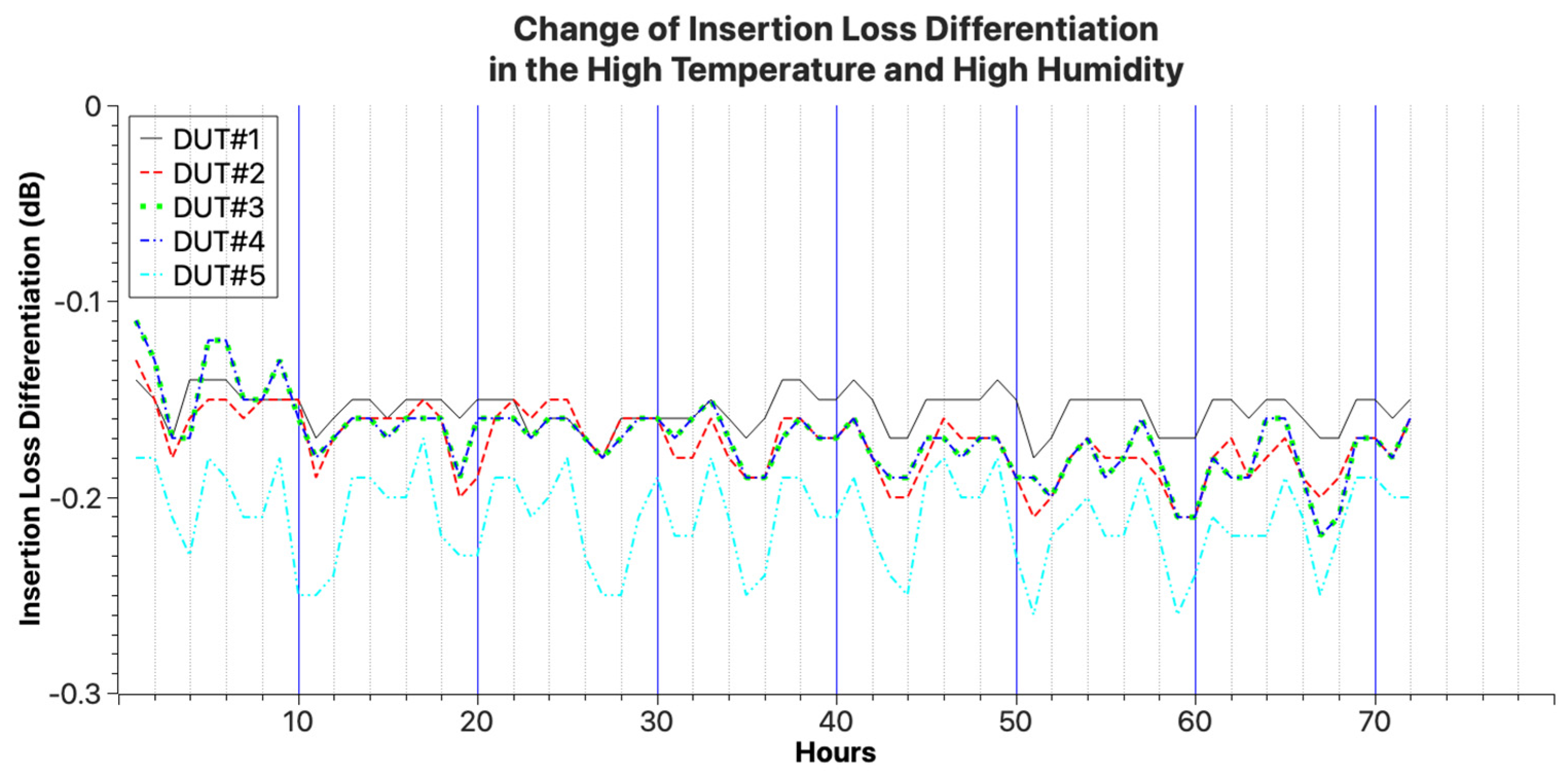
4.2. Optical Connector Performance Test

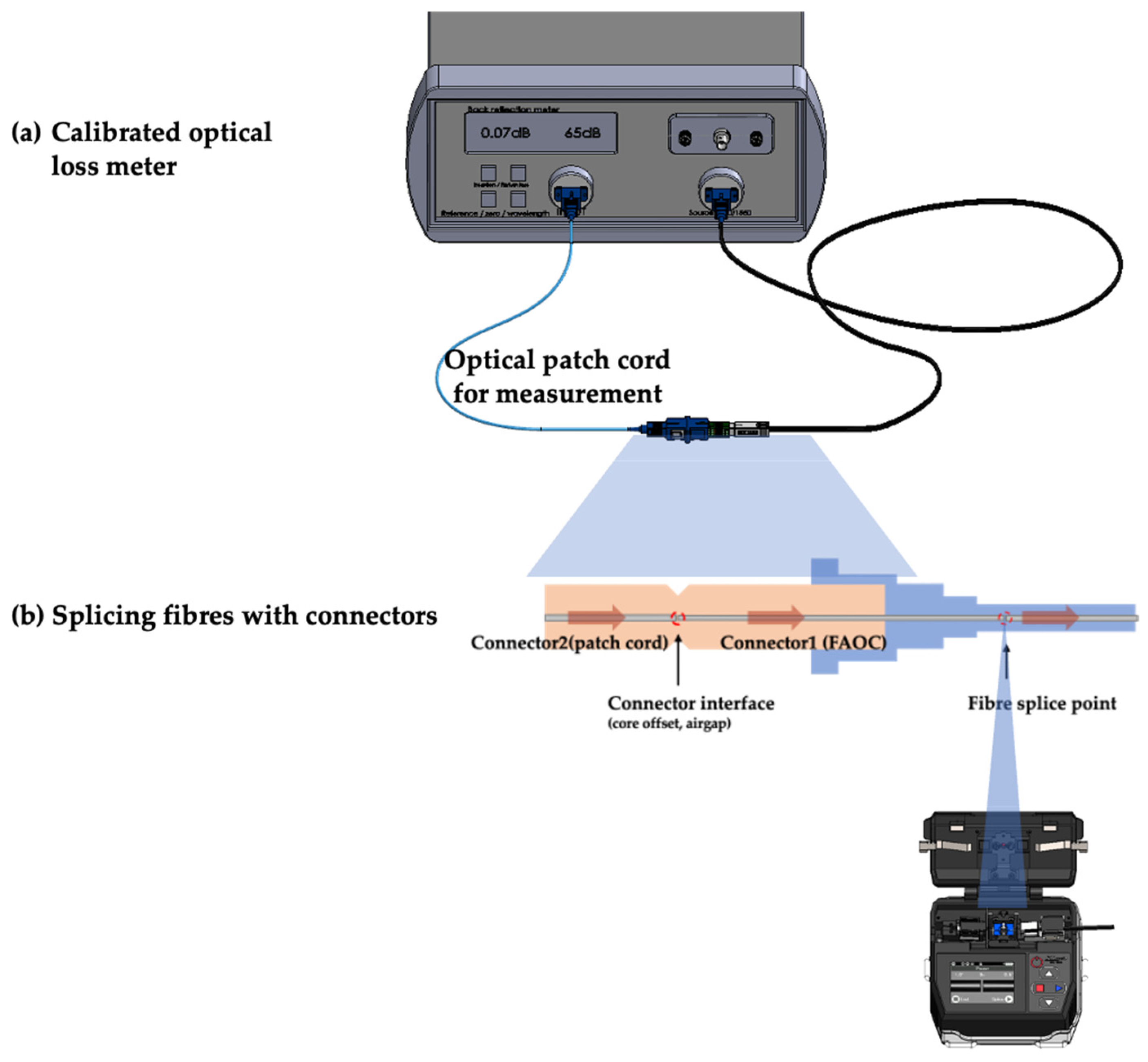
4.2.1. Experimental Procedure

The second experiment was conducted to investigate the performance of the fusion-spliced optical connector. This experiment was divided into two steps. One was to measure the total loss due to fusion splicing and to assemble the optical connector to the optical drop cable. The other was to determine the differences in the optical connector as a function of temperature change. First, to verify the performance of the optical connector developed in this experiment, the fusion-spliced optical connector was fusion-spliced to the optical drop cable, as shown in Figure 15, and the total loss was measured after assembly. The total loss measured included the optical connector termination loss and the fusion splice loss.
Next, the performance of the protective sleeve inside the optical connector was checked by measuring the loss change based on the temperature change in the optical connector. The experiment followed the procedure of the GR-326-CORE [23] temperature cycle tester and the temperature change was measured for nine cycles, each cycle lasting eight hours, as shown in Figure 16. The test setup is shown in Figure 17.

4.2.2. Results of the Experiment

Figure 18 shows the loss characteristics of the fusion-type optical connector equipped with the wing-type ferrule. It is considered to have reasonable characteristics as it includes a connection loss in the cross chapter of the optical connector and a fusion connection loss of −0.14 dB on average.
Using the samples and experimental results, the loss change due to temperature change was measured using the temperature/humidity chamber fixed to 85 °C temperature and 85% humidity. Figure 19 shows the result of the loss variation with temperature for samples 1 to 5. Although the loss tends to increase at low temperatures, it is assumed to be the loss due to the air gap in the connector cross chapter as it is similar to the connector temperature characteristics of the general optical patch cord. No changes in loss were observed at low and high temperatures, which was attributed to the sleeve protection observed.

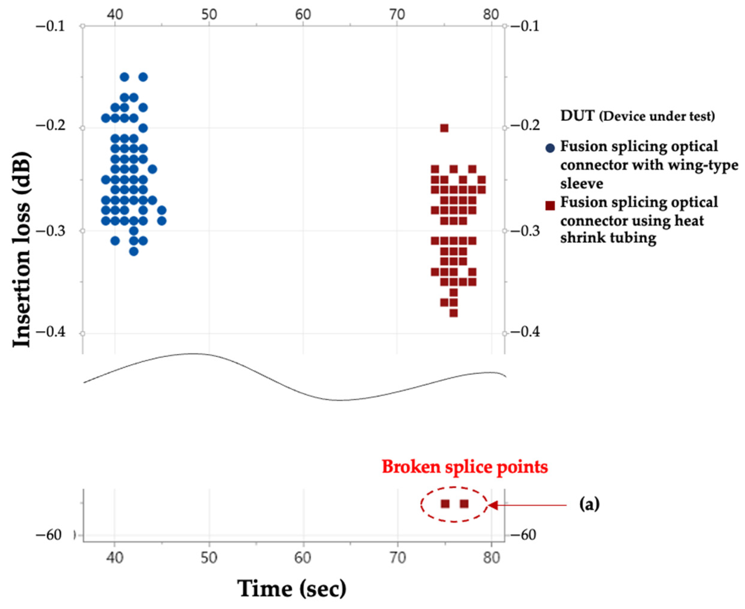
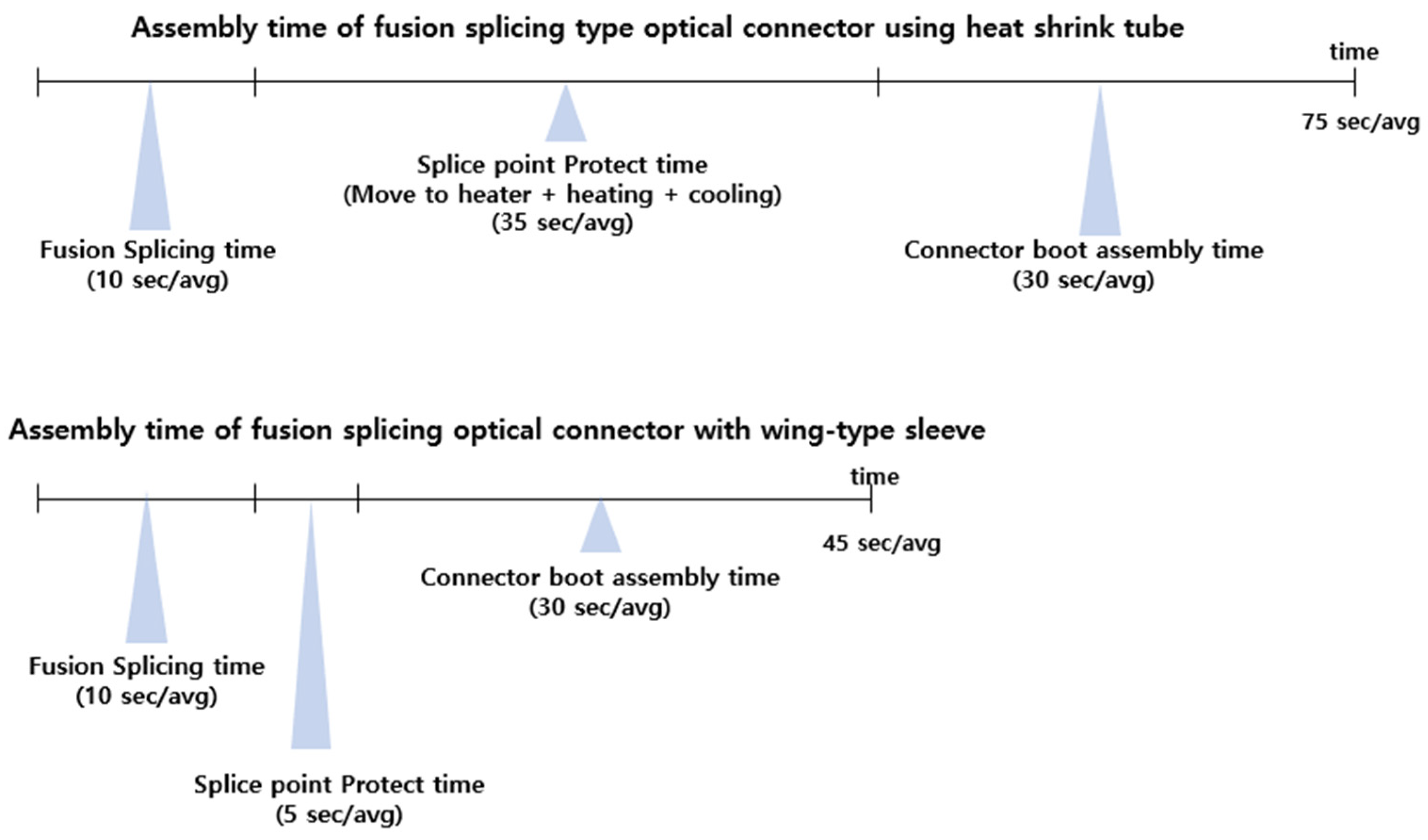
4.3. Assembly Effectiveness Test

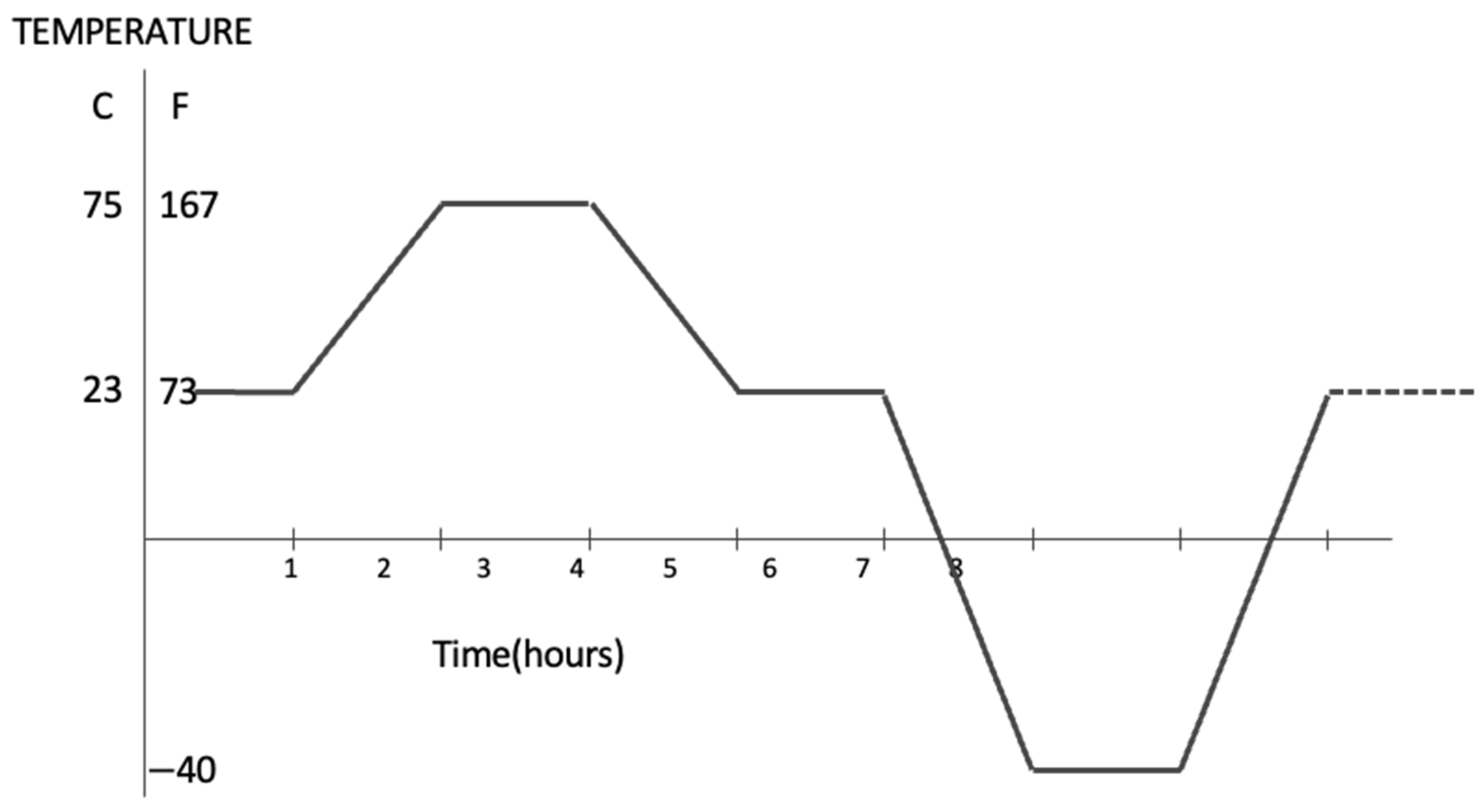
4.3.1. Experimental Procedure

Thirdly, an experiment was conducted to investigate the ease of assembly and the failure rate of the fusion splicer and the optical connector. The optical connector with a wing sleeve developed in this experiment was connected and assembled using the developed fusion splicer, and the fusion splice loss and assembly time were measured as shown in Figure 20. For comparison, a general fusion-spliced optical connector of the tube heating method was fusion-spliced in the same way, and the splice point was protected by a tube and a heater and assembled to measure the splice loss and assembly time of the result. The measurement results of the two samples were compared and analysed.
To measure the time, the total time from the start of the fusion splicer operation to the completion of the optical connector assembly was measured, excluding the preparation process such as stripping the optical fibre coating. The measured time was divided into three stages, fusion splicing, protection, and optical connector boot assembly, so that the time taken to operate the fusion splicer could be distinguished from the time taken by the experimenter’s work.

4.3.2. Results of the Experiment

The results of the third experiment are shown in Figure 21. This is the result of a comparative experiment between the fusion-spliced optical connector equipped with the wing sleeve developed in this paper and the fusion-spliced optical connector using the existing protective tube. The results showed that the insertion losses were similar for both samples, but when measuring the fusion splice, the time to protect the splice point and the time to assemble the optical connector boot, it was confirmed that there was a time difference of 20 s or more. Specifically, the total time required for the splicing and assembly of optical connectors was analysed by dividing it into work stages. Equipment operation time and operator operation time were classified separately. From the analysis results, it was confirmed that the chapter where the time difference occurs is the process of protecting the optical fibre joint, as shown in Figure 22, and it was also confirmed that the point where the fibre disconnection occurs, as shown in Figure 21a, also occurs at the joint protection point.

5. Conclusions

The field-assembled optical connectors installed inside and outside the subscriber’s home for FTTH services are changing from the matching gel-type optical connector to the fusion-splice-type optical connector. The proliferation of fusion-spliced optical connectors faces obstacles due to the size and weight of the fusion splicer and problems with the splice point protection method. To solve this problem, this paper proposed a fusion-spliced optical connector equipped with a wing ferrule that did not use a tube heater or a fusion splicer capable of fusion splicing. It is brought forward to improve the convenience of optical connector fusion splicing and the assembly reliability of the optical connector.
The experimental results showed that the insertion loss of the fusion splicer developed in this paper met the standard of Internet FTTH equipment by less than −0.1 dB. It was confirmed that the work time could be reduced to about 40 s. In addition, unnecessary tube heaters and AC power modules were removed to miniaturise the fusion splicer so that it could work in a small space, and a price reduction can be expected from these removals. It has been experimentally confirmed that the assembly time has been reduced from 75 s to 40 s. In addition, a comparative test with existing products confirmed that assembly reliability had improved.
In the future, FTTH will evolve from bringing optical fibre into the home to FTTD (Fibre To The Desk), where various communication devices and TVs in the home are connected directly to optical cables. It is also expected that there will be more environments that form a network with optical cables in the home. In-home networking environments must be able to be installed and maintained by the residents themselves. To this end, further research should be conducted to popularise the termination of optical cables and the necessary fusion connectors so that they are easily accessible and usable by everyone, making them easy to use and low-cost.

Author Contributions

Conceptualisation, S.S. and B.-c.P.; methodology, S.S. and B.-c.P.; software, B.-c.P.; validation, S.S. and B.-c.P.; formal analysis, S.S. and B.-c.P.; investigation, S.S. and B.-c.P.; resources, S.S. and B.-c.P.; data curation, S.S. and B.-c.P.; writing—original draft preparation, B.-c.P.; writing—review and editing, S.S. and B.-c.P.; visualisation, B.-c.P.; supervision, S.S.; project administration, S.S.; funding acquisition, S.S. and B.-c.P. All authors have read and agreed to the published version of the manuscript.

Funding

This work was supported by the National Research Foundation of Korea (NRF) grant funded by the Korea government, MSIT (No. 2020R1F1A1071819). In addition, this research was supported by the MSIT (Ministry of Science and ICT), Korea, under the ITRC (Information Technology Research Center) support program (IITP-2023-2018-01426) supervised by the IITP (Institute for Information & Communications Technology Promotion). And this paper was supported by a research grant from the Tech University of Korea in 2023.

Data Availability Statement

The data presented in this study are available in this article.

Conflicts of Interest

Author Byung-chul Park was employed by the company Soltech Infonet Co., Ltd. The remaining authors declare that the research was conducted in the absence of any commercial or financial relationships that could be construed as a potential conflict of interest.

References

  1. Edwin, C. Optical Fiber Communications Principles and Practice; ED-Tech Press: London, UK, 2020. [Google Scholar]
  2. Hernandez, J.A.; Sanchez, R.; Martin, I.; Larrabeiti, D. Meeting the Traffic Requirements of Residential Users in the Next Decade with Current FTTH Standards: How Much? How Long? IEEE Commun. Mag. 2019, 3, 120–125. [Google Scholar] [CrossRef]
  3. Gupta, H.; Gupta, P.; Kumar, P.; Gupta, A.K.; Kumar, P.M. Passive Optical Networks: Review and Road Ahead. In Proceedings of the TENCON 2018—2018 IEEE Region 10 Conference, Jeju, Republic of Korea, 28–31 October 2018. [Google Scholar] [CrossRef]
  4. Takai, H.; Osamu, Y. Optical fiber cable and wiring techniques for fiber to the home (FTTH). Opt. Fiber Technol. 2009, 15, 380–387. [Google Scholar] [CrossRef]
  5. Lee, H.J.; Park, B.C. Field Assembly Optical Connector Configured to Prevent Optical Fiber Bending. Patent Application No. US17/299,776. Available online: https://patents.google.com/patent/US20220019026A1/en (accessed on 9 November 2023).
  6. Wang, H.; Li, X.; Jin, L.; Hu, G. Evaluation of splicing quality in few-mode optical fibers. Opt. Commun. 2022, 507, 127596. [Google Scholar] [CrossRef]
  7. Hu, L.; Yuan, C. Analysis of Splice Loss of Single-Mode Optical Fiber in the High Altitude Environment. Coatings 2021, 11, 876. [Google Scholar] [CrossRef]
  8. Noriyuki, K. Optical Fiber Fusion Splice System. Patent Application No. US14/178,483. Available online: https://patents.google.com/patent/US20140157830A1/en (accessed on 9 November 2023).
  9. Mahmoud, A. Design and Implementation of a Fiber to the Home FTTH Access Network based on GPON. Int. J. Comput. Appl. 2014, 92, 30–42. [Google Scholar]
  10. Veng, T.; Edvold, B. Method for Measuring Optical Fiber Strain Applied to Determine Strain in Fusion Splice Protectors. IEEE Photonics Technol. Lett. 2013, 25, 1517–1519. [Google Scholar] [CrossRef]
  11. Iwashita, Y.; Tan, S.; Takizawa, K.; Kawanishi, N. Field-Installable Fusion Splice Connector. In Proceedings of the OFC/NFOEC 2008, San Diego, CA, USA, 24–28 February 2008; pp. 1–5. [Google Scholar] [CrossRef]
  12. Soni, S.; Nagpure, S.; Shaikh, A.; Nandwalkar, J.R.; Pete, D.J. Improvement in Performance of OFC & Fusion Splice Loss. In Proceedings of the 2020 6th International Conference on Advanced Computing and Communication Systems (ICACCS), Coimbatore, India, 6–7 March 2020; pp. 851–855. [Google Scholar] [CrossRef]
  13. UCL Swift Americas. “Termination of a Splice-on Connectors Using the Swift KF4A Fusion Splicer”, Educational Video, 2:58. Available online: https://youtu.be/8VrG3YEm0yA (accessed on 9 November 2023).
  14. Iwashita, Y.; Saito, S.; Takashima, T. Development of a sophisticated sub-micro fusion splicer for FTTP applications. In Proceedings of the 2006 Optical Fiber Communication Conference and the National Fiber Optic Engineers Conference, Anaheim, CA, USA, 5–10 March 2006. [Google Scholar] [CrossRef]
  15. Fusion Crocodile Splice on Connectors, Diamond the Fiber Meeting, Last Modified December 2022. Available online: https://www.diamond-fo.com/products/product-single/fusion-crocodile-soc/ (accessed on 2 March 2023).
  16. Chen, D.Z.; Zimmel, S.; Lu, Y.; Gronvall, E. A new factory splice-on fiber optic connector with high performance and reliability by machine automation. In Proceedings of the 2016 Optical Fiber Communications Conference and Exhibition (OFC), Anaheim, CA, USA, 20–22 March 2016. [Google Scholar]
  17. Sugita, E.; Nagase, R.; Kanayama, K.; Shintaku, T. SC-type single-mode optical fiber connectors. J. Light. Technol. 1989, 7, 1689–1696. [Google Scholar] [CrossRef]
  18. Tsukamoto, M.; Konda; Hoshino, Y.; Okada, N. Development of novel cicada-resistant optical drop cable. In Proceedings of the 2010 Conference on Optical Fiber Communication (OFC/NFOEC), Collocated National Fiber Optic Engineers Conference, San Diego, CA, USA, 30 June 2010. [Google Scholar] [CrossRef]
  19. Cho, M.P.; Lin, H.S.; Yong, Y.T.; Phua, Y.N.; Yong, T.K.; Rahman, F.A. Characterisation of continuous arc discharge system as a fusion heat source for fused fiber components. In Proceedings of the 4th Annual IEEE International Conference on Cyber Technology in Automation, Control and Intelligent, Hong Kong, China, 4–7 June 2014. [Google Scholar] [CrossRef]
  20. Thompson, J. Writing Instrument. Patent Application No. EP87305912A. Available online: https://patents.google.com/patent/EP0252694A1/en (accessed on 9 November 2023).
  21. RM3 SERIES BACK REFLECTION METER User’s Manual, Rev 002; JDS Uniphase: Nepean, ON, Canada, 2010.
  22. Information and Communication Construction Design Criteria; Korea Information & Communication Industry Institute (KICI): Seoul, Republic of Korea, 2018; Available online: https://www.kica.or.kr/file/download/3b353349-3204-4a79-911f-bce21397df32 (accessed on 9 November 2023).
  23. Telcordia GR-326-CORE; Generic Requirements for Single-Mode Optical Connectors and Jumper Assemblies. Available online: https://telecom-info.njdepot.ericsson.net/site-cgi/ido/docs.cgi?ID=SEARCH&DOCUMENT=GR-326 (accessed on 9 November 2023).
Figure 1. Working environment of an existing optical fibre fusion splicer.
Electronics 12 04629 g001
Figure 2. Fusion splicing of an optical connector head.
Electronics 12 04629 g002
Figure 3. Transfer of cable and connector head to the heater to protect the splice point of the fusion-spliced optical connector.
Electronics 12 04629 g003
Figure 4. A fusion-spliced optical connector head with a wing sleeve.
Electronics 12 04629 g004
Figure 5. Structure of the fusion-spliced wing-type ferrule.
Electronics 12 04629 g005
Figure 6. Cable boot mounting structure in our design.
Electronics 12 04629 g006
Figure 7. Comparison of fusion splicers.
Electronics 12 04629 g007
Figure 8. Internal structure of the developed fusion splicer for fusion splicing of optical connectors.
Electronics 12 04629 g008
Figure 9. Operation of the lift/lower module.
Electronics 12 04629 g009
Figure 10. Structure of the raising/lowering module using the click method.
Electronics 12 04629 g010
Figure 11. Structure of the fusion splicing module with lift/lower function.
Electronics 12 04629 g011
Figure 12. Size and structure of the developed fusion splicer.
Electronics 12 04629 g012
Figure 13. Fusion splicing fibre to fibre.
Electronics 12 04629 g013
Figure 14. Measurement results of insertion loss characteristics of the fusion splice.
Electronics 12 04629 g014
Figure 15. Method of experiment.
Electronics 12 04629 g015
Figure 16. Temperature cycle graph.
Electronics 12 04629 g016
Figure 17. Composition of temperature cycle test.
Electronics 12 04629 g017
Figure 18. Loss characteristics of an optical connector with fusion splice.
Electronics 12 04629 g018
Figure 19. Variation in insertion loss with temperature.
Electronics 12 04629 g019
Figure 20. Method of experiment.
Electronics 12 04629 g020
Figure 21. Comparison of splice loss and splice time of two types of DUTs.
Electronics 12 04629 g021
Figure 22. Comparison analysis of assembly time of two types of DUTs.
Electronics 12 04629 g022
Table 1. Comparison of physical specifications.
ProductsSize (W × D × H) (mm)Heating Tube NecessaryCable
Movement Necessary
Weight (g)Price (USD)
(Estimates)
DVP-740142 × 122 × 138OO1950USD 150
YD-AI381 × 332.7 × 309.9OO8280USD 2300
CETI-6481B154 × 120 × 130OO1800USD 3000
Ours119 × 137 × 80XX680USD 500
Disclaimer/Publisher’s Note: The statements, opinions and data contained in all publications are solely those of the individual author(s) and contributor(s) and not of MDPI and/or the editor(s). MDPI and/or the editor(s) disclaim responsibility for any injury to people or property resulting from any ideas, methods, instructions or products referred to in the content.

