Article

Design of a Low Power Condenser for Underwater Ships

Faculty of Mechanical and Electrical Engineering, University of Electronic Science and Technology of China, Chengdu 611731, China
*
Author to whom correspondence should be addressed.
Electronics 2023, 12(17), 3681; https://doi.org/10.3390/electronics12173681
Submission received: 9 August 2023 / Revised: 25 August 2023 / Accepted: 27 August 2023 / Published: 31 August 2023
(This article belongs to the Special Issue Emerging Technologies and Applications in Low-Carbon Energy Systems)

Abstract

:
The power unit generates heat during the operation of a ship, and excessive temperature may cause damage to equipment. Therefore, it is necessary to design a cooling system for the multi-working conditions and variable working conditions of a ship to reduce the adverse effects of high temperatures. The traditional pipeline heat exchanger is inefficient, resulting in a serious waste of resources. In this work, under the background of energy conservation and emission reduction, a new type of cooling system is designed. Using a jet condenser with direct mixing of hot and cold fluids, the technology of frequency conversion regulation is used to optimize the energy conservation of the ship’s cooling system. By adjusting the frequency of the circulating water pump and using the PID algorithm to control the flow of cooling water, the temperature of the condensate outlet can be controlled under variable operating conditions, achieving the goal of maintaining the temperature within a certain range. Because of the complex structure and controlled process of the cooling water system, which has the characteristics of non-linearity and hysteresis, PID control has some limitations. Based on this, the BP neural network is used to adjust and tune the parameters of PID control, thus optimizing the control speed and achieving accuracy in the new cooling system.

1. Introduction

A ship’s cooling system is an important part of its stable operation. With the ongoing development of the ship industry, cooling systems of ships also need to be continuously optimized. The control method of the cooling system needs to be designed from the perspective of economy, safety, energy conservation, and emission reduction.
The central cooling water system of a ship is composed of two circuits—a low temperature cooling circuit and high temperature cooling circuit. The low-temperature circuit is partially cooled by heat exchange between seawater and low-temperature fresh water to achieve the purpose of cooling circulating water. The high-temperature circuit part achieves cooling of high-temperature steam through heat exchange between high-temperature and low-temperature fresh water [1,2]. At present, research on ship cooling water is mostly based on the central cooling water system, and optimization and development are carried out on this basis, as follows:
(1)
Sea water will not make direct contact the heat exchange equipment and cooler, which will greatly reduce the risk of corrosion by sea water and improve the safety of marine power equipment.
(2)
The whole system is divided into two cooling circuits, which reduces the influence of external factors on the temperature of the main engine and improves the temperature stability of the high-temperature cooling circuit [1,3].
In recent years, with the continuous development and maturity of frequency conversion technology, frequency conversion control has been widely used in ship cooling water systems.
Shanghai Maritime University carried out frequency conversion control on the seawater pump of a ship, and established its mathematical model through the operating characteristic curve of the seawater pump. The central cooling water system was modeled and simulated, and the mathematical relationship between inlet and outlet temperature difference and heat load was obtained, which verified the feasibility and economy of frequency conversion control [4].
Gerasimos Theotokatos of the UK analyzed the energy-saving effect of a ship cooling water system with frequency conversion control under different loads by calculating the pipeline loss and pump consumption of sea water, as well as low-temperature and high-temperature fresh water systems [5].
Because of the complexity of the marine diesel engine cooling water system, the parameters of the temperature controller designed by the PID algorithm are difficult to adjust and the control effect is not very good, so the combination of artificial intelligence and PID has become a new research hotspot [6].
Du Yuheng of Dalian Maritime University and others put forward the method of “fuzzy control of cooling water temperature of marine diesel engine”, which combines fuzzy control with PI, PD, or PID control to control the cooling water temperature [7].
T.K. Teng and others used the combination of a genetic algorithm and PID to automatically select the best PID parameters for each generation by breeding, crossing, and mutation, and conducted online PID tuning [8].
Traditional condensers use pipes for heat exchange, but the heat exchange efficiency is not high. Therefore, there have been many applications and studies on the water atomization technology of steam water direct mixing heat exchangers, both domestically and internationally [9].
Harbin Turbine Works conducted water spray experiments on the film-forming effect of spray nozzles with different diameters of jet condensers under different pressure differentials, and compared them with the same type of spray nozzles abroad [10].
At present, the temperature control mode of the cooling water system of the real ship is still dominated by conventional PID control, and the controller parameters are adjusted by experience. However, the control effect is not very good when the working condition changes during ship navigation, which requires a long adjustment transition time or a large overshoot [11]. The new cooling system uses the technology of a jet condenser and variable frequency regulation to carry out systematic energy-saving optimization for the ship cooling system, and controls the sea water flow and cooling water flow through the combination of PID and artificial intelligence algorithms in order to achieve the control goal that the temperature can be adjusted quickly and maintained within a certain range.
The remaining sections are organized as follows: the model design of the new cooling system is introduced in Section 2. In Section 3, we introduce the design of the control algorithm. The simulation in Section 4 verifies the feasibility of the results. The conclusion and future research plans are presented in Section 5.

2. Cooling System Design

The low power consumption of the new cooling system is mainly reflected through two aspects: the use of jet condenser for the condensation process and the use of variable frequency regulation to control the condensation circulating pump.

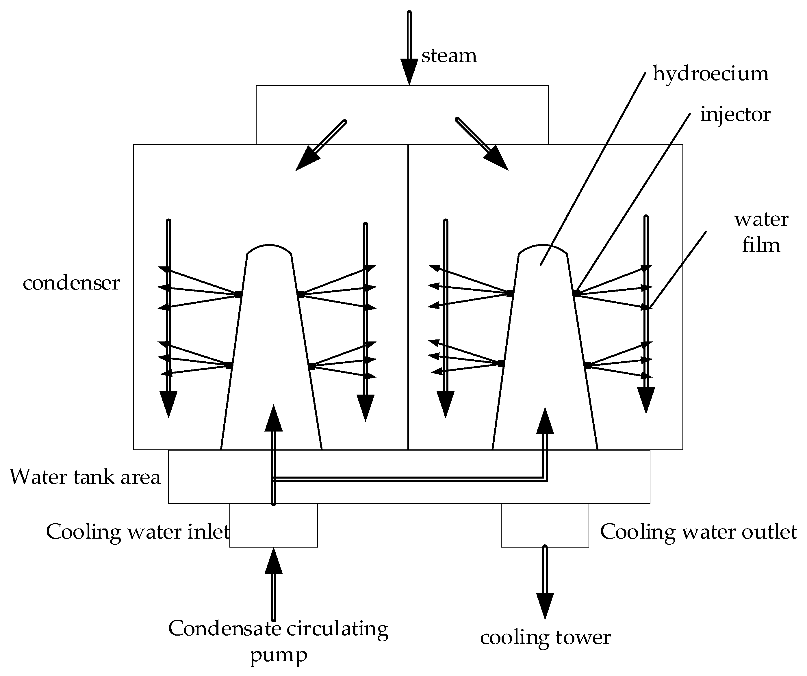
2.1. Introduction to the Principle of Jet Condenser

The difference between the jet condenser and the traditional shell-and-tube heat exchanger is that the heat exchange in the shell-and-tube heat exchanger is carried out through the heat exchange tube wall, while the jet condenser is directly mixed with cold and hot fluids for heat exchange, and its schematic diagram is shown in Figure 1. The circulating cooling water flows into the water chamber at a certain height difference, and forms a large water film after being sprayed by the nozzle. The water film makes direct contact with the steam for heat exchange [10].
The application of an atomizing nozzle can form a large enough steam−water contact surface area, so that the cooling water and the steam entering the condenser are fully mixed for heat exchange, the steam is rapidly condensed, and the cooling water is heated. This condensing device avoids the steam latent heat being taken away by the circulating cooling water in the conventional heat exchange process, greatly reduces the fuel consumption, and has an obvious energy-saving effect [12]. At the same time, because of the direct contact and continuous condensation of the cooling water film ejected from the nozzle of the jet condenser, there was no heat transfer end difference caused by the heat transfer of the cooling pipe during the heat exchange process, and the theoretical end difference was only related to the amount of non-condensable steam entering the condenser, namely, the air volume [13].

2.2. Introduction to Ship Operating Conditions

For the overall ship cooling system, the steam generator simulated different operating conditions based on different inputs and provided the corresponding steam flow rate to the hybrid condenser. The corresponding steam flow rates for the four operating conditions were 2 t/h, 1.5 t/h, 1 t/h, and 0.5 t/h, respectively. The steam flow rate corresponding to condition one was 2 t/h, condition two was 1.5 t/h, condition three was 1 t/h, and condition four was 0.5 t/h.
In the overall modeling process of the cooling system, the above four operating conditions were designed, and based on this, changes in operating conditions were simulated, and the temperature of the condensate outlet under variable operating conditions was controlled.

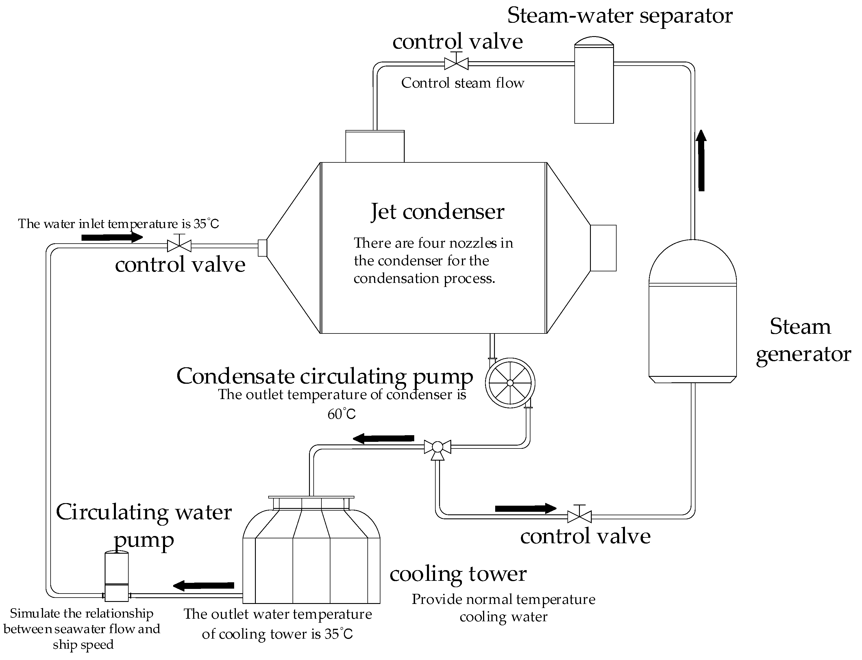
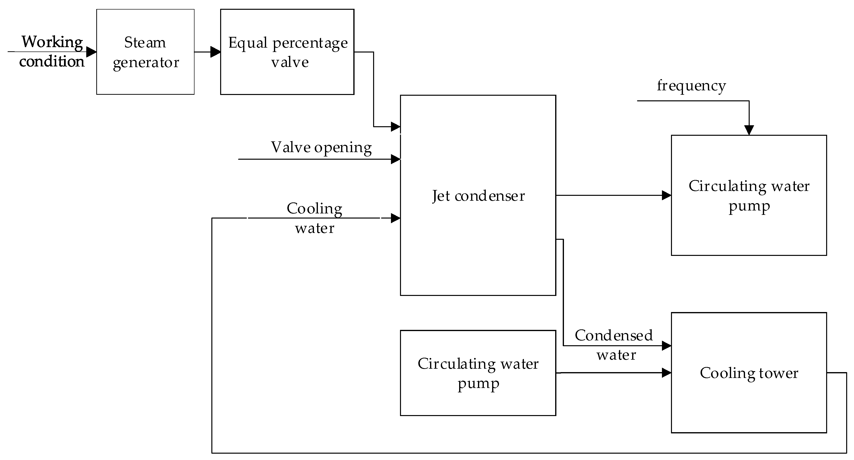
2.3. Overall Design of the Low Power Consumption New Cooling System

The ship cooling system simulated different working conditions based on different inputs. When the working conditions changed, the input steam was condensed through a hybrid condenser, and the output condensate water outlet temperature was 60 °C. The condensate at the outlet was cooled by the cooling tower, and 35 °C normal temperature water was obtained as the cooling water for circulation. According to the opening of the control valve and the frequency of the condensate circulating pump, the cooling water entering the condenser to participate in the condensation process was adjusted. The overall flow model of the new condenser is shown in Figure 2. The arrows in the figure represent the direction of flow of high-temperature steam and circulating water in the cooling system.

3. System Modeling

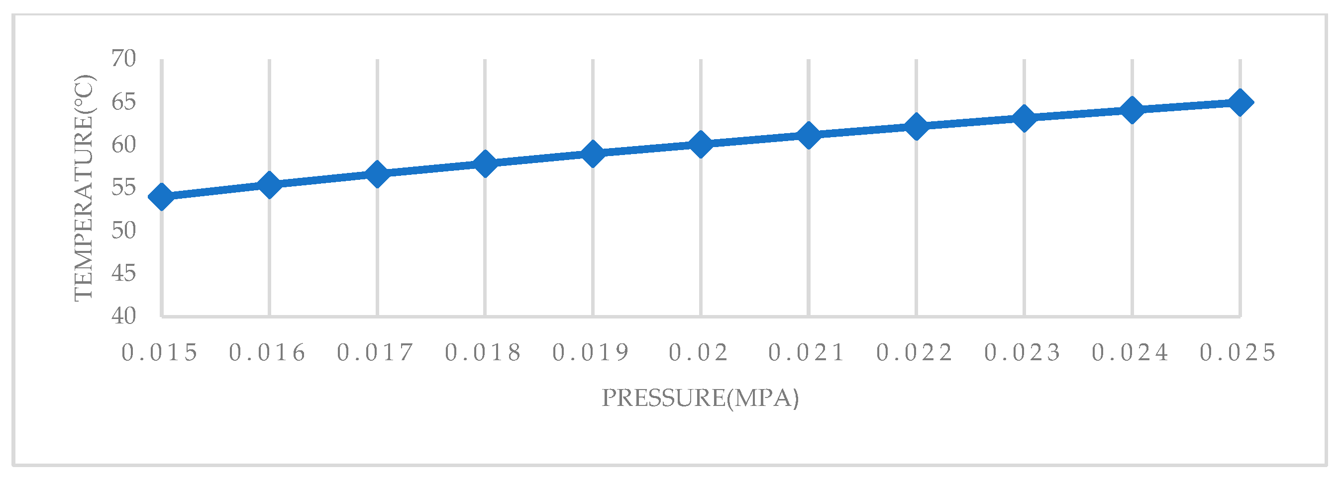
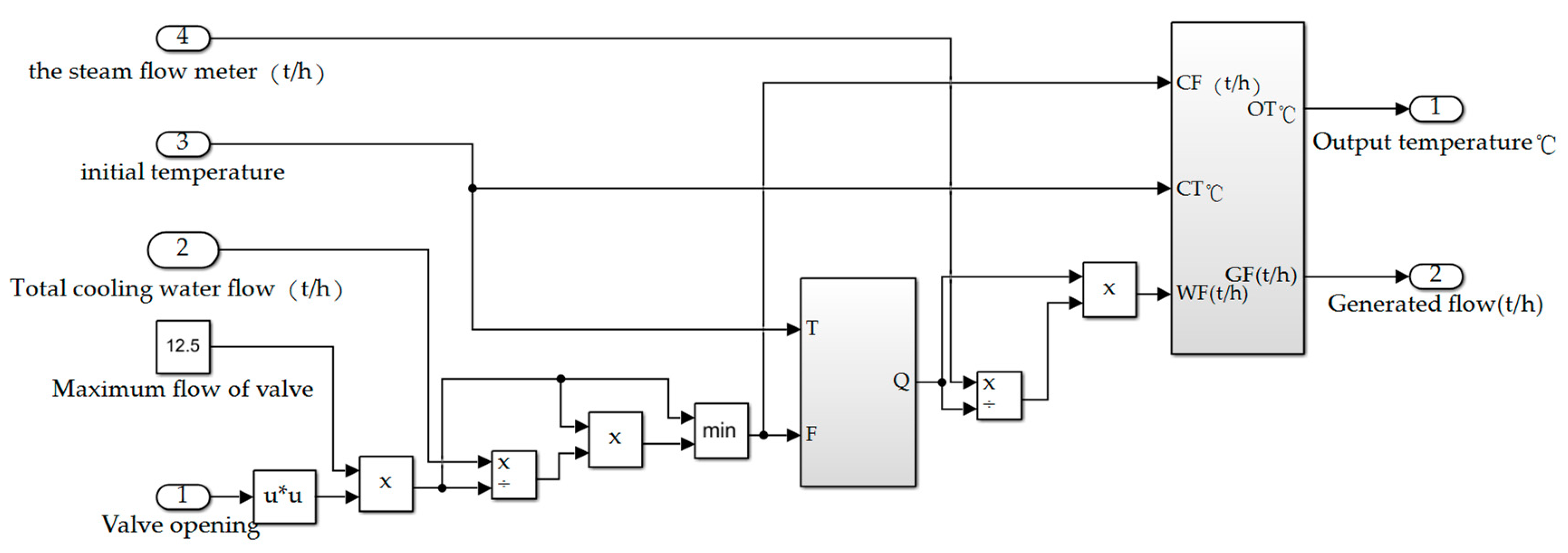
3.1. Jet Condenser Modeling

As the main condensing equipment in the condensing system, the jet condenser is responsible for the condensation of saturated water vapor generated in the steam generator, converting it into fresh water. Part of the condensed fresh water returns to the steam generator, and the other part enters the cooling tower for cooling. There are four water chambers in the jet condenser, and the flow of each water chamber can be controlled separately by the valve. In order to simplify the calculation, the following assumptions are made:
The water film is continuous;
The air content in the condenser is certain;
The heat transfer coefficient K is known;
The corresponding saturation temperature under saturated steam can be obtained by referring to the corresponding relationship table, and part of the data are extracted to draw Figure 3.
After investigating and reading the literature, the mathematical model of jet condenser used in this paper mainly includes the following formulas: first, the heat calculation formula [12,14,15,16,17].
q = K 1 F 1 Δ t m = G w c p w ( t 2 t 1 ) / 3.6
Δ t m = ( t 2 t 1 ) / l n ( t s a t t 1 t s a t t 2 )
q —heat exchange between water film and steam of each nozzle, K J / s ;
K 1 —water film heat transfer coefficient, W / m 2 · ° C ;
F 1 —water film heat transfer area of nozzle, m 2 ;
G w —nozzle flow, t / h ;
c p w —specific heat capacity of water at constant pressure, K J / k g · ° C ;
t 1 —temperature at the beginning of water film, °C;
t 2 —water film terminal temperature, °C;
Δ t m —logarithmic mean temperature difference, °C;
t s a t —steam saturation temperature at corresponding pressure, °C.
According to Formulas (1) and (2), the heat transfer coefficient K 1 can be determined according to the experimental data provided,
t 2 = t s a t ( t s a t t 1 ) e K 1 F 1 / G w c p w / 3.6
t 2 can be obtained from (3), and the heat transfer q can be obtained by substituting it into Equation (1). According to the heat transfer, the condensed steam volume Δ G s   ( k g / h ) can be calculated as follows,
Δ G s = q / r
In the formula, r is the latent heat of vaporization of saturated water, K J / k g ;
Using the obtained flow rate of the nozzle, condensed steam volume, water film terminal temperature, and steam saturation temperature under corresponding pressure, the condensate outlet temperature t 0 of the condenser can be obtained from the following formula,
t 0 = Δ G s · t s a t + G w · t 2 Δ G s + G w
Referring to the thermal calculation formula in the jet condenser and taking into account other factors in the condenser, the established Simulink simulation model of the jet condenser has seven input ends, namely, the opening of water chamber 1 valve, the opening of water chamber 2 valve, the opening of water chamber 3 valve, the opening of water chamber 4 valve, the total flow of cooling water, the initial temperature of water film, and the steam flow, and the output end is the generated flow and the condensate temperature. The established Simulink simulation model is shown in Figure 4.

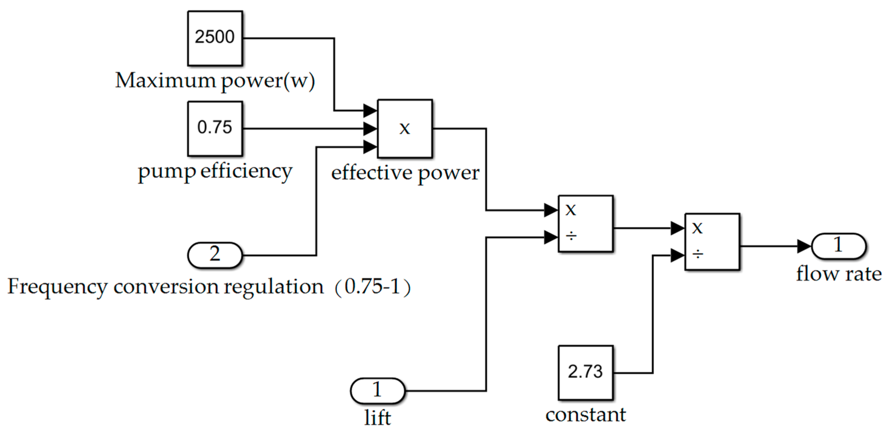
3.2. Circulating Water Pump Modeling

The circulating water pump used in the pipeline is generally a single-stage centrifugal pump, which is a vane pump. It increases the energy of the liquid through the high-speed rotating impeller.
The main performance parameters of the centrifugal pump are head H and flow Q G . The pump characteristic curve composed of these two parameters is called the Q−H curve [18].
The actual Q−H curve is provided by the manufacturer or the data are fitted by the experiment.
In practical engineering, there is an empirical formula for the flow of pipeline water pump
Q m = P η 2.37 H
In the formula, P—pump shaft power, W;
η —pump efficiency;
H—head of water pump, m.
The Simulink simulation model of the circulating water pump is established according to the commonly used formula of the pump flow and head. The module model has three inputs, namely “rated head (m)”, “variable frequency regulation coefficient”, and “extracted cooling water volume (t/h)”. The third input variable is the pumping function of the circulating water pump, which can be temporarily ignored during the simulation of the sub-module. The output of the model is “output flow (t/h)”. The Simulink simulation package model of the circulating water pump is shown in Figure 5.

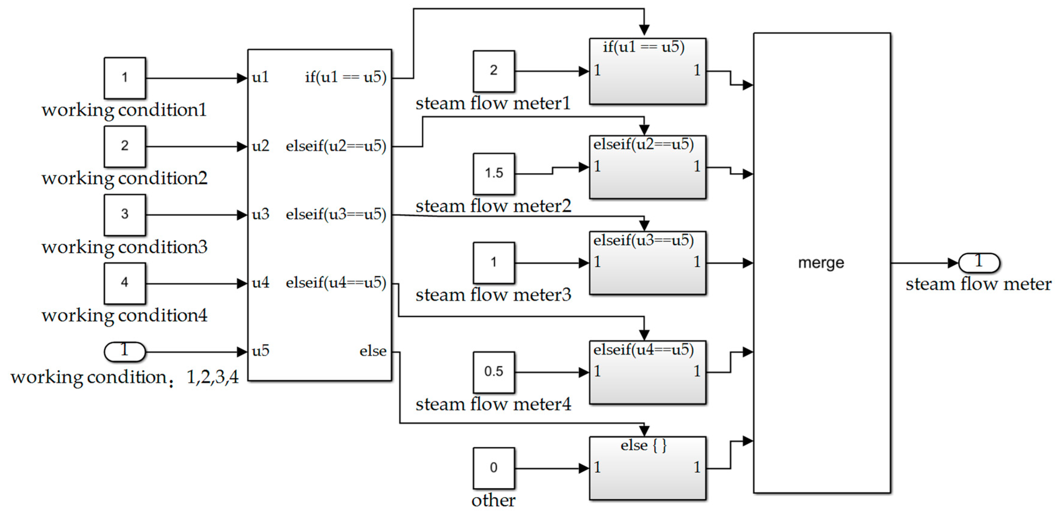
3.3. Steam Generator Modeling

The function of the steam generator is to generate saturated water vapor and send it to the jet condenser for condensation. In this circulating cooling system, there are four stable conditions for the steam generator, and the corresponding steam flow rates under the four conditions were 2 t/h, 1.5 t/h, 1 t/h, and 0.5 t/h, respectively. In the process of Simulink modeling, it was assumed that condition 1 corresponded to a steam flow of 2 t/h, condition 2 corresponded to a steam flow of 1.5 t/h, and so on. The Simulink simulation package model of the steam generator is shown in Figure 6.

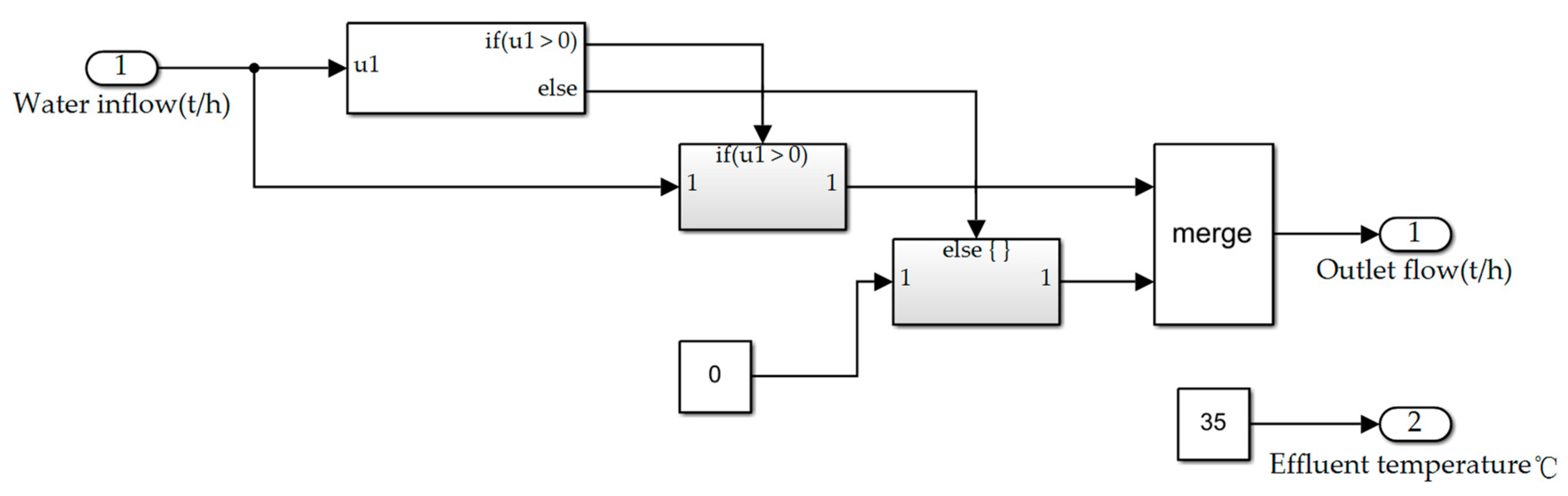
3.4. Cooling Tower Modeling

In this condensing system, the function of the cooling tower is to provide sea water at a normal temperature, and the temperature of the cooling water at a normal temperature required in this condensing system was 35 °C. The inlet of the cooling tower was connected to the outlet of the hybrid condenser, and it was cooled to a specified temperature of 35 °C. The flow into the cooling tower was consistent with the output flow, and both were equal. When establishing the cooling tower model, the input variables were “inlet water flow t/h” and “inlet water temperature °C”, and the two outputs were “outlet water flow” and “outlet water temperature °C”. The Simulink simulation package model of the cooling tower is shown in Figure 7.

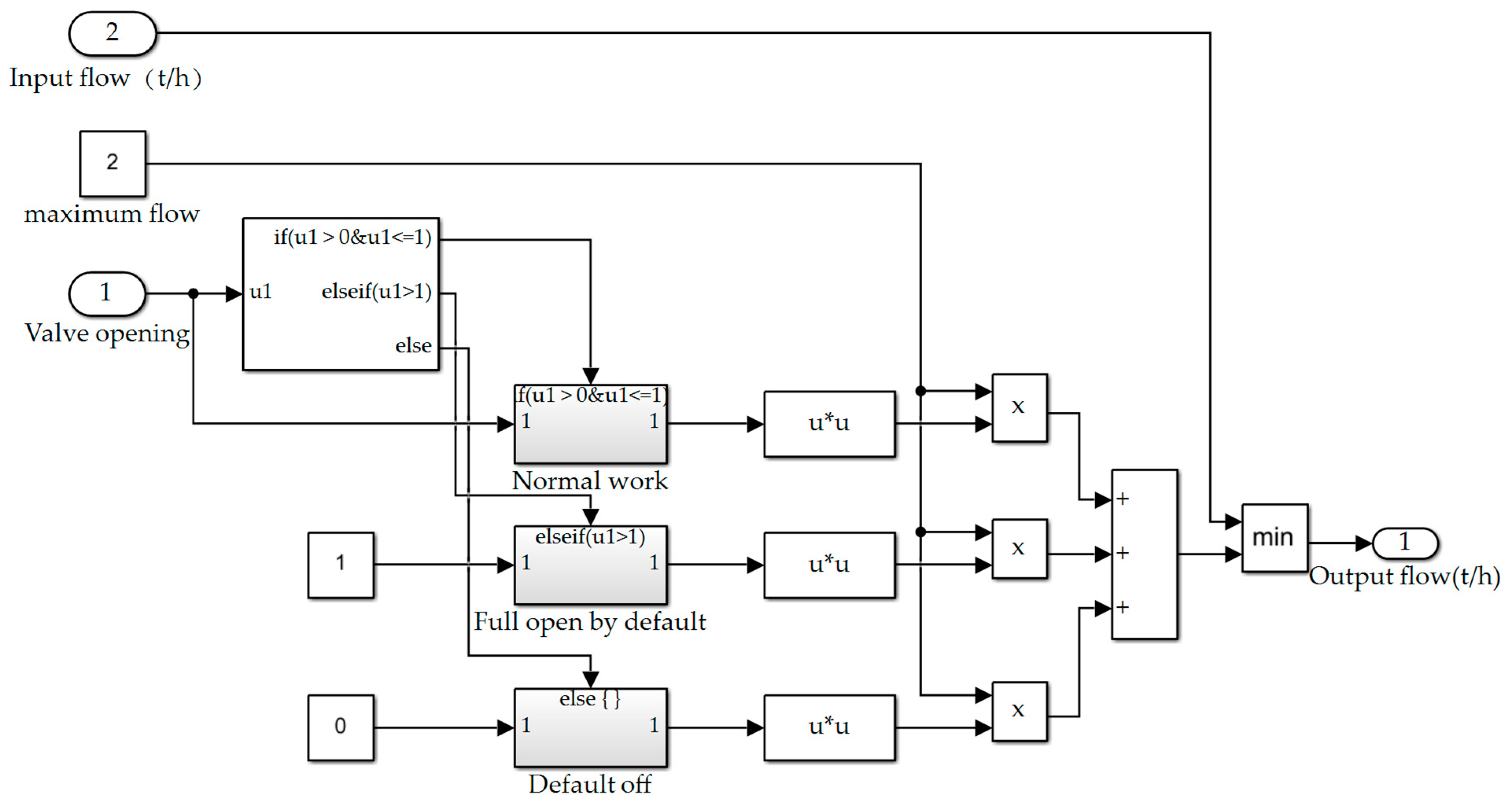
3.5. Equal Percentage Valve Modeling

The valves initially proposed for the condensate system were equal percentage regulating valves. The equal percentage characteristic curve of the control valve means that the relative stroke of the equal percentage characteristic was not in a linear relationship with the relative flow. The change in flow caused by the change in unit stroke at each point of the stroke was proportional to the flow at this point, and the percentage of flow change was equal [19]. So, its advantage was that when the flow rate was small, the flow rate did not change much. When the flow rate was large, the flow rate changed greatly. That is, it had the same adjustment accuracy at different openings.
In this paper, the characteristic curve of the flow and opening of the valve was simply selected as the parabolic function with the opening facing upwards. The maximum flow that the preliminarily selected valve could pass was 80 t/h, and the valve opening changed from 0–1. If it exceeded 1, the valve was fully open by default, and if it was lower than 0, the valve was closed by default. The Simulink simulation package model of valve is shown in Figure 8.

3.6. Overall System Modeling

The overall model framework of the ship’s overall cooling system is shown in Figure 9, and the sub-models are established and connected in Simulink according to this structural framework.
The input variables and output variables of the simulation model are shown in Table 1.

4. Control System Design

4.1. Introduction of th BP Neural Network PID Control Theory

As the PID control effect depends on its parameter setting, it is difficult to achieve the optimal effect under several conditions by using a group of parameters for temperature control under variable conditions, so it is necessary to optimize the PID parameters. In order to make the PID controller adaptive, the artificial neural network was added to the PID controller to automatically adjust the parameters of the controller, k p , k i and k d , under the condition of the variable working conditions of the system [20].
The back-propagation learning algorithm (BP neural network) of the multilayer feed forward network was proposed by many scholars in the 1980s. It is an algorithm applied to a multilayer feed forward network using the gradient descent method. The model structure is shown in Figure 10. The network is composed of an input layer, hidden layer, and output layer, where u and y are input and output, respectively.
A three-layer neural network was adopted. The number of neurons in the input layer is m 1 , and the number of neurons in the hidden layer is m 2 . As the purpose of the neural network was to adjust the PID parameters, the number of neurons in the output layer of the neural network was set to 3, and the output was is k p , k i , k d [21].
The structure of the PID controller based on the BP neural network is shown in Figure 11.

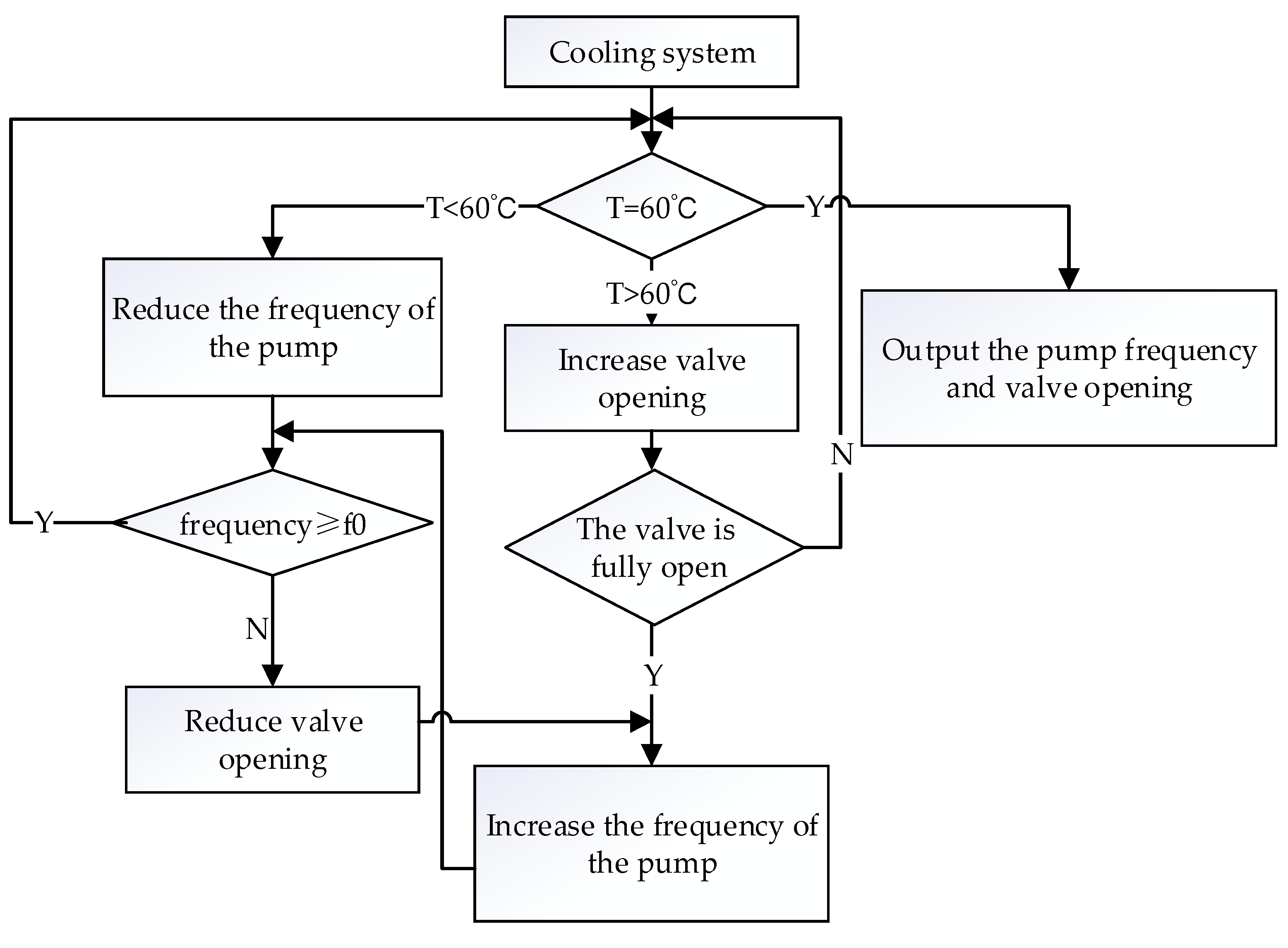
4.2. Cooling System Control Scheme

In the case of variable working conditions, the ship cooling system needed to develop different control schemes to meet the requirements of the system so as to control the vacuum, super cooling and condensate outlet temperature within a certain range, and to achieve the goal of energy conservation. In the case of changing working conditions, the controlled parameter was the temperature of the condensate outlet T1, which can ensure the normal and efficient operation of the equipment by controlling the constant water temperature. The control quantity that could be changed included the power of the circulating water pump and the opening of the valve. The current maximum flow and head could be changed by changing the power of the circulating water pump; by changing the valve opening, the flow could be further controlled under the premise of maximum flow. Therefore, the control scheme was designed to change the control object under different operating conditions. During the process of changing working conditions, the power of the circulating water pump and the opening of the valve were controlled separately to achieve the temperature control goals and to achieve energy conservation.
We took the water outlet temperature T1 at the condenser as the controlled parameter of the internal cooling system, and the goal was to keep its temperature at 60 °C. Under variable working conditions, it was assumed that the steam flow would gradually decrease from the full working condition. At this time, the nozzle valve was kept fully open. By reducing the power of the condensate circulating pump, the surplus flow of the pump during operation or the surplus head were reduced, and the temperature T1 of the condensate outlet was controlled within an error range of 60 °C [22]. In order to ensure the safe and efficient operation of the variable frequency pump and to achieve sufficient outlet pressure, its operating frequency value needed to be higher than the minimum safe frequency f0. When the frequency of the variable frequency pump was reduced to f0, the frequency could not be further reduced. If T1 could not reach the set value of 60 °C at this time, the outlet temperature of the condensation was controlled by adjusting the opening of nozzle valve, and the bypass valve of circulating pump was opened in parallel. When the steam flow rate increased from low operating conditions, the opening of the nozzle valve was adjusted first. If the target temperature could not be reached even with the valve fully open, the power of the variable frequency pump was adjusted until the temperature stabilized to the target value. The control scheme flow chart of the jet condenser is shown in Figure 12.

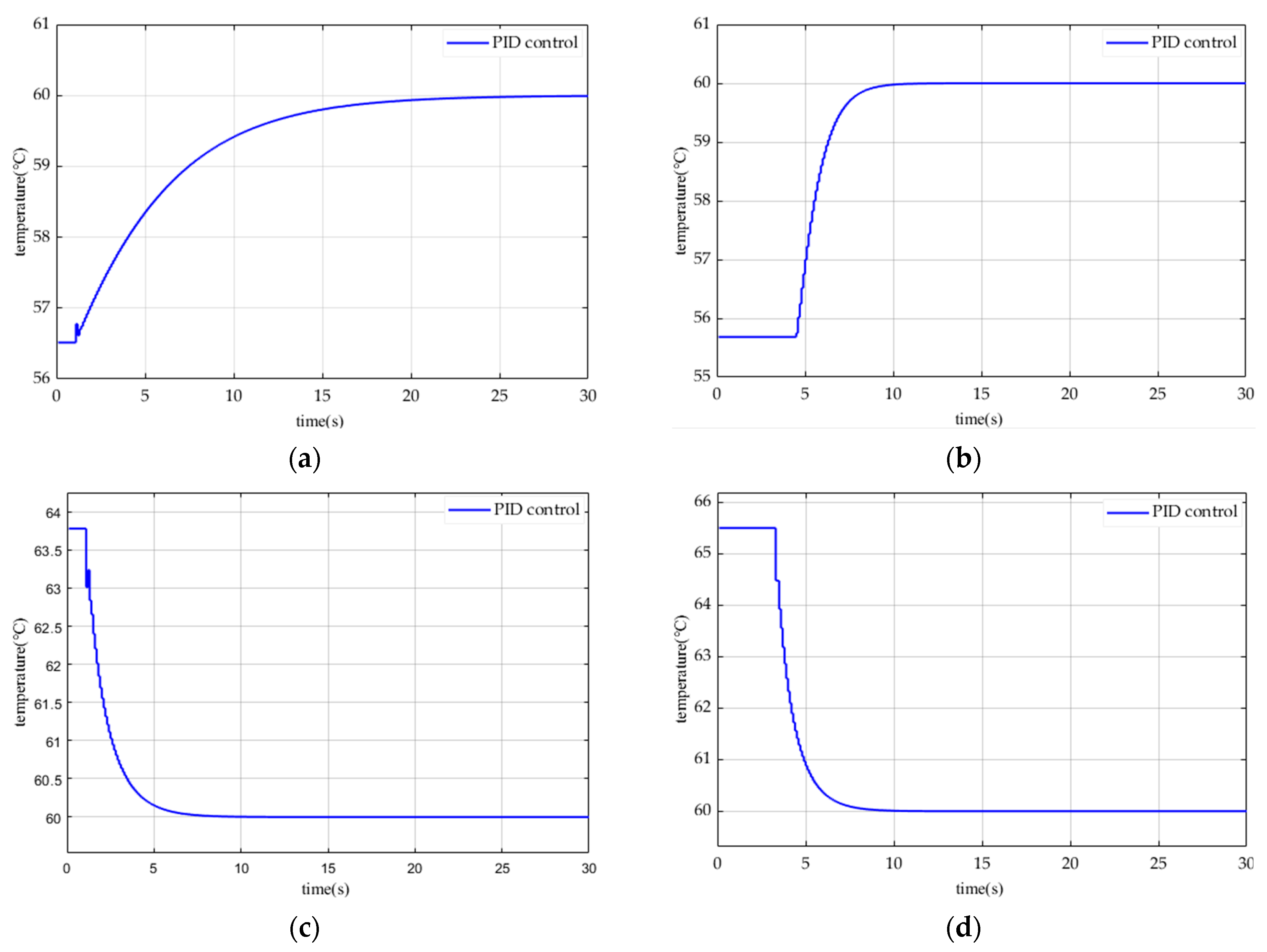
4.3. Design of Ship Cooling Control System Based on PID Algorithm

Under four stable operating conditions, the system can ensure that the water temperature at the outlet of the hybrid condenser is stable within the allowable range of a 60 °C error. Under condition 1, the valve was fully open and the pump was at 0.9. Under condition 2, the valve opening was 0.8 and the pump opening was 0.75. Under condition 3, the valve opening was 0.65 and the pump opening was 0.75. Under condition 4, the valve opening was 0.46 and the pump opening was 0.75. Therefore, temperature control was no longer required for the cooling system under stable operating conditions.
Under variable operating conditions, the structure of the ship’s cooling system was complex and the accurate transfer function of the mathematical model could not be obtained. Therefore, the condenser used Matlab Function to write two incremental PID to control the valve and condensation circulating pump, separately.
There were six types of variable operating conditions, namely, the upward operating conditions from operating condition 4 to operating condition 3, from operating condition 3 to operating condition 2, from operating condition 2 to operating condition 1, and the downward operating conditions from operating condition 1 to operating condition 2, from operating condition 2 to operating condition 3, and from operating condition 3 to operating condition 4.
In order to study the ability of PID control to adjust the temperature of the model, two groups of temperature curves were selected for observation when the working conditions changed under the conditions of rising and falling. The simulation results are shown in Figure 13. When changing from condition 1 to condition 2 under stable operating conditions, the valve opening and circulating water pump frequency values remained under stable operating conditions before changing, and the temperature control effect was observed through the simulation. The simulation results are shown in Figure 13a. For the change from condition 2 to condition 3, the simulation results are shown in Figure 13b. For the change from condition 4 to condition 3, the simulation results are shown in Figure 13c. For the change from condition 3 to condition 2, the simulation results are shown in Figure 13d.
It can be seen from the simulation image that PID control can adjust the temperature to a stable temperature of 60 °C under variable working conditions, which has a good control effect on the control system, but when the working conditions of the controlled object change, the control effect also changes. In order to achieve a better control effect under all of the working conditions, the PID parameters needed to be continuously adjusted. Therefore, the combination of neural network and PID control could make the temperature regulation of the ship cooling system more ideal by using the self-learning and adaptive ability of the neural network.

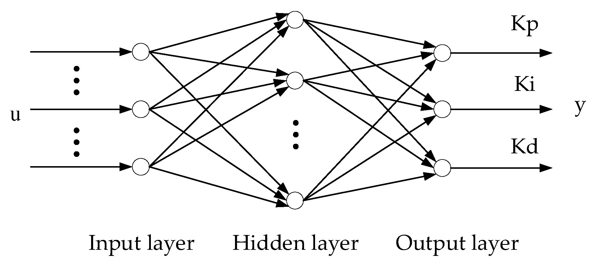
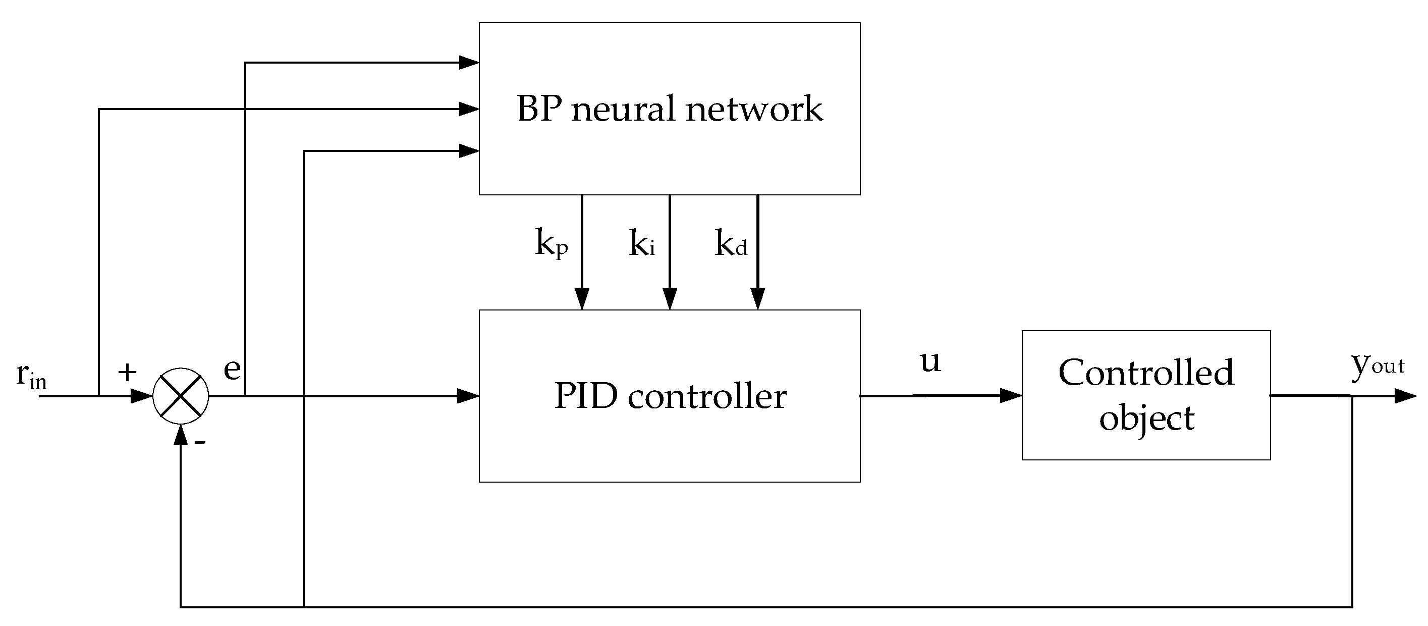
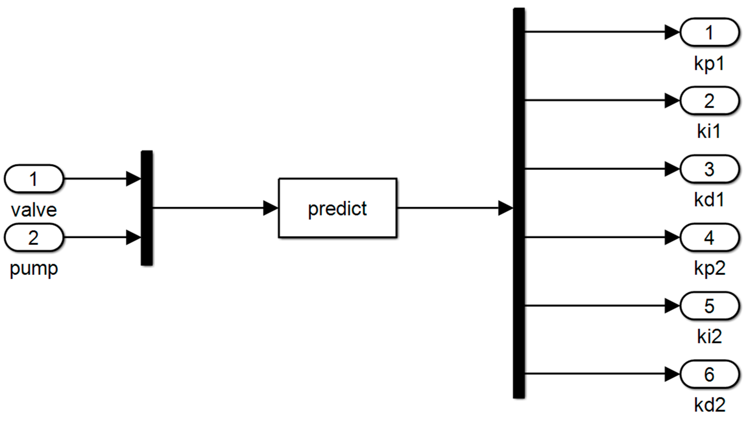
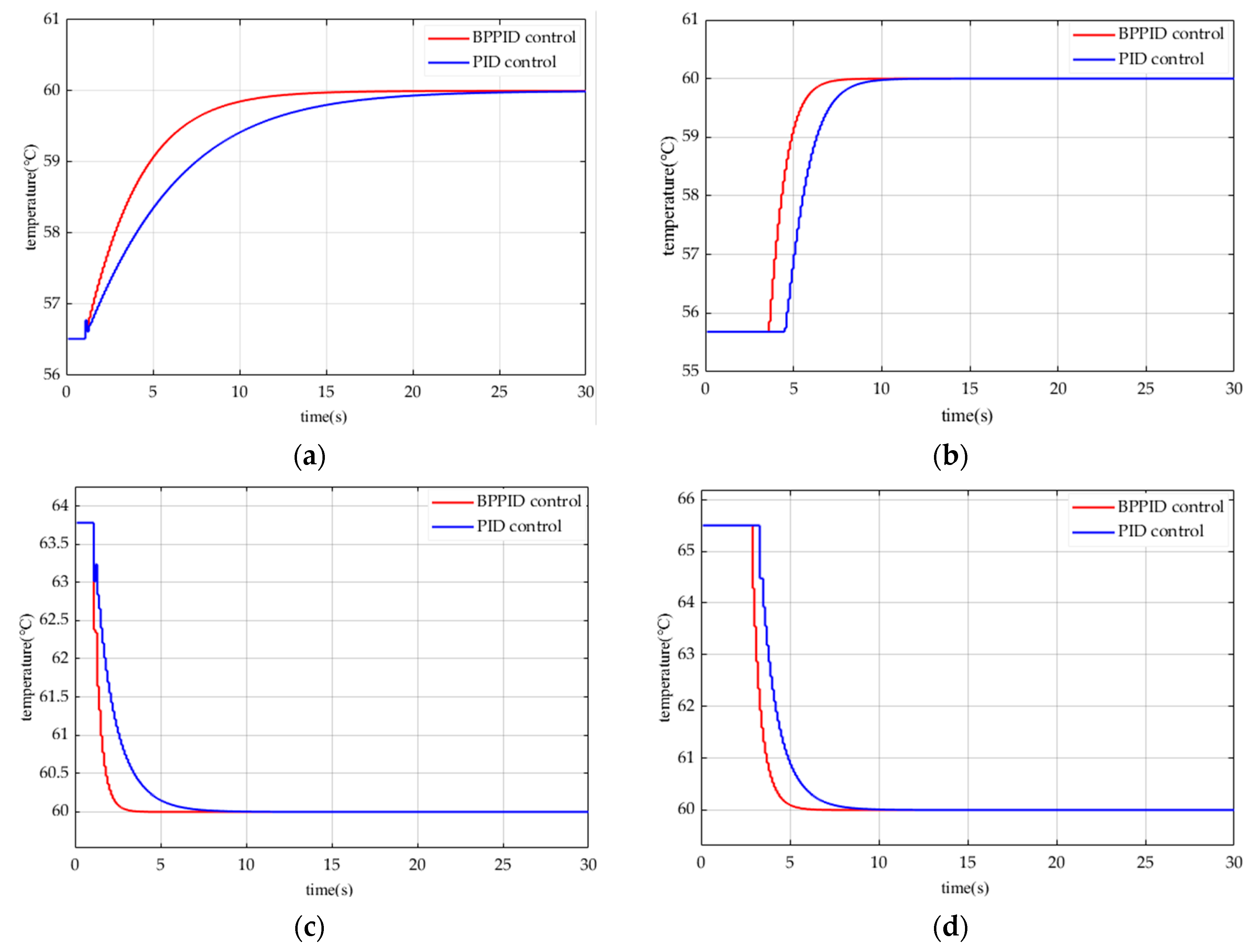
4.4. Design of Ship Cooling Control System Based on BP Neural Network

A three-layer feed forward neural network was designed, and the neural network was used to adjust the three parameters of the PID controller in real time according to the relationship between the number of hidden layer neurons m2 and the number of input layer neurons m1 in the three-layer BP network [23]:
m 2 = 2 m 1 + 1
The number of neurons in the design input layer was 2, which was the valve opening and the frequency of the circulating water pump; the number of neurons in the hidden layer was 5, and the number of neurons in the output layer was 6, which were the parameters of two groups of PID control. Neural network training and simulation test verification were carried out using the neural network fitting toolbox of the MATLAB platform [24]. We set the training data to 70%, the verification data to 15%, and the test data to 15%. The trained BP network was encapsulated into the BPNN module in Simulink through S-Function to adjust the parameters of the PID module. The simulation model of the sub-module neural network PID controller BPNN is shown in Figure 14.
In order to compare the temperature control effects of conventional PID and neural network PID controllers on the cooling water system, we selected several groups of variable operating conditions that were the same as the conventional PID simulation, and only changed the controller under the same other conditions. Simulation experiments were conducted and the simulation results were compared. The four groups of simulation results are shown in Figure 15. Among them, the simulation results are shown in Figure 15a when changing from condition 1 to condition 2. When changing from condition 2 to condition 3, the simulation results are shown in Figure 15b. When changing from condition 4 to condition 3, the simulation results are shown in Figure 15c. When changing from condition 3 to condition 2, and the simulation results are shown in Figure 15d.
In Figure 15a, PID control could stabilize to the target temperature for about 23 s, while BPPID control could stabilize to the target temperature for about 15 s, reducing the stabilization time by 35%. In Figure 15b, PID control could stabilize to the target temperature for about 10 s, while BPPID control could stabilize to the target temperature for about 7.5 s, reducing the stabilization time by 25%. In Figure 15c, PID control can stabilize to the target temperature for about 7 s, while BPPID control could stabilize to the target temperature for about 4 s, reducing the stabilization time by 43%. In Figure 15a, PID control could stabilize to the target temperature for about 8.5 s, while BPPID control could stabilize to the target temperature for about 6 s, reducing the stabilization time by 29%.
Comparing the control effects of the two controllers under the conditions of rising and falling, it was found that the regulation effect of the two controllers under the conditions of high working conditions was not as good as that under the conditions of low working conditions, and under the same conditions, the BPPID controller took less time to adjust and stabilize to the target temperature than the conventional PID controller, and the control effect was better.

5. Summary

Conventional PID control has a simple structure and mature technology, which is a common control technology in industrial engineering. However, because of the problem of parameter adjustment, the PID controller has obvious defects in control performance under the condition of complicated modern industrial objects. The neural network results in the control system possessing stronger learning and adaptability. Compared with the traditional PID algorithm control, the neural network PID control has the ability to approximate the nonlinear function arbitrarily, thus realizing the nonlinear control. The information in the neural network is distributed and processed in parallel, so it has a better processing accuracy and fault tolerance. In the training process, you can find the rule information from the sample data, which results in an adaptive ability [3]. The adaptive self-learning of neural network technology and its ability to deal with nonlinear problems allows the parameters of the PID controller to be adjustable and helps obtain a better regulation quality.
The temperature control process of ship cooling water is a complex process. In this paper, the system was appropriately simplified during the modeling process, and the simulation results were obtained under ideal conditions. There were certain differences between the model and the actual ship system, leading to certain errors in the simulation results. The accuracy of the model needs to be further improved. In future research, various parts of the model will be optimized and corrected based on the actual situation of the ship, which can record the differences between the actual sampling samples and the default sampling samples of the simulation system [25]. At the same time, the BP neural network will use the measured dataset as training data to further optimize the simulation results.
The combination of BP neural network and PID overcomes the problem that traditional PID parameters cannot be adjusted, but it also has some defects such as being difficult to jump out of the local minimum and a slow convergence speed [26]. With the continuous development of intelligent control, it is possible to optimize the existing model according to other types of intelligent control, such as genetic algorithm, fuzzy theory, particle swarm algorithm, and the use of the LSTM model to train longer sequences and develop a new intelligent controller to improve the defects in BP neural network learning [27,28,29].

Author Contributions

Methodology, S.S.; data curation, J.C.; writing—original draft, C.L.; project administration, D.G. All authors have read and agreed to the published version of the manuscript.

Funding

This research was funded by China Shipbuilding Industry Corporation 719th Research Institute [220624].

Data Availability Statement

The data presented in this study are available in this article.

Acknowledgments

The author of this article is very grateful for the help provided by the following experts and personnel: Xiangbo Ding participated in the drawing of the picture, Ruifan Dong provided some literature references, and the 719 Research Institute of China Shipbuilding Industry Corporation provided financial support. Thanks are also here!

Conflicts of Interest

All of the authors disclosed no relevant relationships.

References

  1. Qi, X.; Jiao, J.; Tang, T.; Chu, Y.; Shi, S. Study on Optimize Design of Central Cooling System. In Proceedings of the IEEE 2nd Information Technology, Networking, Electronic and Automation Control Conference (ITNEC), Chengdu, China, 15–17 December 2017; pp. 1512–1515. [Google Scholar]
  2. Liu, J.F.; Wang, J.; Li, G.P. Analysis of energy saving technology for Central Air Conditioning water system operation. In Proceedings of the International Conference on Mechanical Design and Simulation (MDS), Wuhan, China, 18–20 March 2022. [Google Scholar]
  3. Hunt, K.J.; Sbarbaro, D.; Zbikowski, R.; Gawthrop, P.J. Neural Networks for Control-Systems—A Survey. Automatica 1992, 28, 1083–1112. [Google Scholar] [CrossRef]
  4. Wang, H.; Wang, F.; Huang, Y.; Zhang, L. The Research of Energy-saving in Air Conditioning Water Cooling System by Frequency conversion Pump and Constant Pressure Control. In Proceedings of the 2nd International Conference on Mechanics and Control Engineering (ICMCE 2013), Beijing, China, 1–2 September 2013; pp. 1207–1210. [Google Scholar]
  5. Theotokatos, G.; Sfakianakis, K.; Vassalos, D. Investigation of ship cooling system operation for improving energy efficiency. J. Mar. Sci. Technol. 2017, 22, 38–50. [Google Scholar] [CrossRef]
  6. Li, T.Y.; Chen, L.; Jensen, C.S.; Pedersen, T.B.; Gao, Y.; Hu, J.; Soc, I.C. Evolutionary Clustering of Moving Objects. In Proceedings of the 38th IEEE International Conference on Data Engineering (ICDE), Kuala Lumpur, Malaysia, 9–11 May 2022; pp. 2399–2411. [Google Scholar]
  7. Yang, J. Fuzzy Control for Variable Cooling Water Flow System. In Proceedings of the International Conference on Building Materials and Structural Engineering (BMSE 2012), Wuhan, China, 19–20 March 2012; pp. 105–108. [Google Scholar]
  8. Teng, T.K.; Shieh, J.S.; Chen, C.S. Genetic algorithms applied in online autotuning PID parameters of a liquid-level control system. Trans. Inst. Meas. Control 2003, 25, 433–450. [Google Scholar] [CrossRef]
  9. Tirmizi, S.A.; Siddiqui, O.K.; Gandhidasan, P.; Zubair, S.M. Performance analysis of an ejector cooling system with a conventional chilled water system. Appl. Therm. Eng. 2014, 66, 113–121. [Google Scholar] [CrossRef]
  10. Firman; Anshar, M. Study on steam pressure characteristics in various types of nozzles. In Journal of Physics: Conference Series, Proceedings of the 2nd International Conference on Science (ICOS), Makassar, Indonesia, 2–3 November 2017; IOP Publishing: Bristol, UK, 2018. [Google Scholar]
  11. Liu, G.P.; Daley, S. Optimal-tuning PID control for industrial systems. Control Eng. Pract. 2001, 9, 1185–1194. [Google Scholar] [CrossRef]
  12. Eames, I.W.; Milazzo, A.; Paganini, D.; Livi, M. The design, manufacture and testing of a jet-pump chiller for air conditioning and industrial application. Appl. Therm. Eng. 2013, 58, 234–240. [Google Scholar] [CrossRef]
  13. Trofimov, L.I. Intensification of heat transfer in a jet condenser by additional jet splitting using a grid. Theor. Found. Chem. Eng. 2011, 45, 75–80. [Google Scholar] [CrossRef]
  14. Wu, G.T.; Ren, X.D.; Sun, P.Y. Modeling and simulation of cooling water system for marine main engine cylinder liner. J. Harbin Eng. Univ. 2003, 24, 376–379. [Google Scholar]
  15. Su, C.-L.; Chung, W.-L.; Yu, K.-T. An Energy-Savings Evaluation Method for Adjustable-Frequency Drives on Sea Water Cooling Pumps on Ships. In Proceedings of the 49th IEEE/IAS Industrial and Commercial Power Systems Technical Conference (I and CPS), Stone Mountain, GA, USA, 30 April–3 May 2013. [Google Scholar]
  16. Zhang, Y.; Liu, J.; Yang, T.; Liu, J.; Shen, J.; Fang, F. Dynamic modeling and control of direct air-cooling condenser pressure considering couplings with adjacent systems. Energy 2021, 236, 121487. [Google Scholar] [CrossRef]
  17. Chen, J.; Zhang, L.; Fu, Y.; Qian, N.; Jiang, H.; Yang, L. Heat Transfer Characteristics outside the Condenser of a Rotating Heat Pipe Grinding Wheel with a Lateral Air Impinging Jet. J. Therm. Sci. 2021, 30, 493–503. [Google Scholar] [CrossRef]
  18. Wang, J.; Wang, H.; Zhang, H.; Meng, X.-p. Applications of Immune Genetic Algorithm in Frequency Speed Control Pumping Station. In Proceedings of the IEEE International Conference on Automation and Logistics, Shenyang, China, 5–7 August 2009; pp. 1203–1207. [Google Scholar]
  19. Bajsic, I.; Bobic, M. Gain of a control valve with polygonal flow characteristics. Stroj. Vestn.-J. Mech. Eng. 2000, 46, 264–275. [Google Scholar]
  20. Jin, W.; Gao, W.Z.; Gu, S.S.; Wang, F.L. PID-Like controller using a modified neural network. Int. J. Syst. Sci. 1997, 28, 809–815. [Google Scholar] [CrossRef]
  21. Hovakimyan, N.; Nardi, F.; Calise, A.; Kim, N. Adaptive output feedback control of uncertain nonlinear systems using single-hidden-layer neural networks. IEEE Trans. Neural Netw. 2002, 13, 1420–1431. [Google Scholar] [CrossRef]
  22. Su, C.-L.; Chung, W.-L.; Yu, K.-T. An Energy-Savings Evaluation Method for Variable-Frequency-Drive Applications on Ship Central Cooling Systems. IEEE Trans. Ind. Appl. 2014, 50, 1286–1294. [Google Scholar] [CrossRef]
  23. Madhiarasan, M.; Deepa, S.N. A novel criterion to select hidden neuron numbers in improved back propagation networks for wind speed forecasting. Appl. Intell. 2016, 44, 878–893. [Google Scholar] [CrossRef]
  24. Wang, H.; Chang, W.-l. Load Forecasting for Electrical Power System Based on BP Neural Network. In Proceedings of the 1st International Workshop on Education Technology and Computer Science, Wuhan, China, 7–8 March 2009; pp. 702–705. [Google Scholar]
  25. Li, T.; Huang, R.; Chen, L.; Jensen, C.S.; Pedersen, T.B. Compression of Uncertain Trajectories in Road Networks. Proc. Vldb Endow. 2020, 13, 1050–1063. [Google Scholar] [CrossRef]
  26. Wang, L.X.; Wan, F. Structured neural networks for constrained model predictive control. Automatica 2001, 37, 1235–1243. [Google Scholar] [CrossRef]
  27. Hu, Y.; Wang, F.; Qin, L.; Gong, J.; Liu, B. Application of Fuzzy PID Control Algorithm Based on Genetic Self-tuning in Constant Temperature Incubator. In Proceedings of the 32nd Chinese Control And Decision Conference (CCDC), Hefei, China, 22–24 August 2020; pp. 171–176. [Google Scholar]
  28. Zhu, X.; Du, C.; Li, Z.; Wang, J.; Feng, Y. Temperature Control Optimization for Heat Pipe Based on Particle Swarm Optimization. In Proceedings of the 8th International Conference on Instrumentation and Measurement, Computer, Communication and Control (IMCCC), Harbin, China, 19–21 July 2018; pp. 920–923. [Google Scholar]
  29. Li, T.Y.; Chen, L.; Jensen, C.S.; Pedersen, T.B. TRACE: Real-time Compression of Streaming Trajectories in Road Networks. Proc. Vldb Endow. 2021, 14, 1175–1187. [Google Scholar] [CrossRef]
Figure 1. Schematic diagram of the jet condenser.
Electronics 12 03681 g001
Figure 2. Overall flow model diagram of the new condenser.
Electronics 12 03681 g002
Figure 3. Relationship between saturation temperature and pressure.
Electronics 12 03681 g003
Figure 4. Simulink model of the jet condenser.
Electronics 12 03681 g004
Figure 5. Simulink model of the water circulating pump.
Electronics 12 03681 g005
Figure 6. Simulink model of the steam generator.
Electronics 12 03681 g006
Figure 7. Simulink model of the cooling tower.
Electronics 12 03681 g007
Figure 8. Simulink model of the valve.
Electronics 12 03681 g008
Figure 9. Model framework of the ship cooling system.
Electronics 12 03681 g009
Figure 10. BP neural network model.
Electronics 12 03681 g010
Figure 11. PID controller structure based on the BP neural network.
Electronics 12 03681 g011
Figure 12. Flow chart of control scheme of jet condenser.
Electronics 12 03681 g012
Figure 13. PID control temperature change curve: (a) condition 1 changes to condition 2; (b) condition 2 changes to condition 3; (c) condition 4 changes to condition 3; (d) condition 3 changes to condition 2.
Electronics 12 03681 g013
Figure 14. Simulink simulation model of the neural network PID controller module.
Electronics 12 03681 g014
Figure 15. BPPID control temperature change curve: (a) condition 1 changes to condition 2; (b) condition 2 changes to condition 3; (c) condition 4 changes to condition 3; (d) condition 3 changes to condition 2.
Electronics 12 03681 g015
Table 1. Input and output variables of the simulation model.
Input VariablesOutput Variables
Variable NameVariable ValueVariable NameVariable Value
working condition1, 2, 3, 4Steam flow2 t/h, 1.5 t/h, 1 t/h, 0.5 t/h
Steam generator valve opening1Condensate outlet temperature60 °C
Valve opening of condenser water chamber0~1Outlet temperature of cooling tower25 °C
Rated head of circulating water pump12.5 mOutput flow of circulating water pumpChange with frequency
Circulating water pump frequency percentage0.75~1Output flow of condensate circulating pumpChange with frequency
Disclaimer/Publisher’s Note: The statements, opinions and data contained in all publications are solely those of the individual author(s) and contributor(s) and not of MDPI and/or the editor(s). MDPI and/or the editor(s) disclaim responsibility for any injury to people or property resulting from any ideas, methods, instructions or products referred to in the content.

