Article

Hybrid Model Predictive Control with Penalty Factor Based on Image-Based Visual Servoing for Constrained Mobile Robots

School of Electrical Engineering, Nantong University, Nantong 226019, China
*
Authors to whom correspondence should be addressed.
Electronics 2023, 12(14), 3186; https://doi.org/10.3390/electronics12143186
Submission received: 26 June 2023 / Revised: 17 July 2023 / Accepted: 20 July 2023 / Published: 22 July 2023
(This article belongs to the Section Systems & Control Engineering)

Abstract

:
For the constrained mobile robot automatic parking system, the hybrid model predictive control with a penalty factor based on image-based visual servoing (IBVS) is proposed to address the problem of feature point loss and emergency braking in dynamic obstacle scenarios caused by excessive target bias gain when using traditional IBVS control methods. The traditional IBVS control is transformed into an optimization problem with constraints in the finite time domain, by defining the optimization function based on the mobile robot’s positional deviation and image feature point deviation, while using actuator saturation and speed limit as constraints. Based on this, a convex optimization function with penalty factors is defined and combined with incremental model predictive control. This control strategy could ensure the emergency braking performance of the mobile robot when the image feature points are massively obscured by obstacles in dynamic scenes, while improving the accuracy and real-time of its trajectory tracking control. Finally, simulation comparisons are conducted to verify the effectiveness of the proposed control method.

1. Introduction

With the development of science and technology, automatic parking has become a research hotspot, and the trajectory tracking control of mobile robots is a key technology related to the accuracy of automatic parking [1]. In particular, the research of visual servo-based automatic parking and emergency braking for mobile robots constrained by feature points has received increasing attention [2].
Classical visual servo control is mainly divided into position-based visual servoing control (PBVS), image-based visual servoing control (IBVS) and hybrid visual servoing control [3]. The PBVS control needs to define the error signal in the three-dimensional Euclidean space for three-dimensional reconstruction. The direct error control in the three-dimensional space can ensure its convergence [4]. However, this method is vulnerable to system calibration errors and visual measurement noise [5]. The IBVS is controlled by defining the error signal in the two-dimensional image plane [6]. It does not need the 3D pose information of the mobile robot and is robust to the system disturbances [7]. The IBVS has been combined with advanced control algorithms to realize automatic parking for mobile robots. In [8], for the problem of lack of depth information and parameter estimation in the visual servo control of mobile robots, the sliding mode control method based on IBVS three-view pair-pole geometry is proposed, to solve the depth correction problem and ensure the closed-loop stability of the system by expanding the pair-pole geometry to three pictures. In [9], for the limitation that the camera plane must be parallel to the motion plane in the visual servo control of mobile robots, the IBVS-based adaptive controller is proposed, which has a simple structure and high efficiency to achieve good trajectory tracking control performance. Nonetheless, the target deviation gain of the mobile robot visual servo control system is prone to excessive selection, when the camera parameters are not accurately calibrated. Then, the above control methods are difficult to deal with the problem of feature point loss and system instability caused by excessive target deviation gain.
For the problem of losing feature points and system instability due to excessive target deviation gain in the vision servo control system of mobile robots, it is necessary to constrain image feature points to maintain them within the field of view at all times [10]. The existing studies are divided into two main approaches: algorithm design and hardware adjustment. In [11], for the visual servo control of mobile robots, a time-varying continuous hybrid visual servo controller is designed to realize consistent tracking and pose correction for mobile robots, to solve the problem that the target feature points are difficult to maintain within the field of view of the camera, and to ensure the stability of feature point tracking; in [12], for the image feature point constraint problem, a two-stage active visual servo scheme for mobile robots is proposed. By using an external mobile platform camera device, it could keep the feature points around the center of the image plane to achieve mechanical tracking of the image feature points and ensure that the image feature points are always maintained within the field of view. However, none of the above methods are calibrated with camera specific parameters. In [13], for the problem of constrained mobile robot visual servo control when the camera parameters are not accurately calibrated, the specific parameters of the camera are estimated and an adaptive continuous visual servo controller is designed to realize the trajectory tracking control of the mobile robot under the image feature point constraint. The internal constraints such as actuator saturation and speed limitation are not considered in the above methods, and these methods are not universally applicable.
Model predictive control (MPC) is a model-based optimal control strategy [14], which owns superiorities such as rolling optimization, constraint handling, and state prediction [15]. It is suitable for handling the internal constraints of the control system and predicting the system state [16]. The model predictive control algorithm has been introduced to the IBVS-based mobile robot control system. In [17], for the mobile robot automatic parking control system, the constrained IBVS-based model predictive control method is proposed to ensure the accuracy of the mobile robot trajectory tracking control, by considering the internal constraints such as actuator saturation and speed limitation. But the computational burden is large and it is difficult to be applied practically. In [18], for the problem of poor real-time image processing and rolling optimization of the combination of IBVS and MPC, the IBVS-based model predictive control self-triggering switching scheme is designed to reduce the computation time, by eliminating the need for visual measurement and computation of control inputs at two consecutive triggering moments. But it is difficult to meet the high accuracy requirements of mobile robot trajectory tracking control. To solve the problem of difficulty in ensuring both real-time and accuracy of the IBVS-based mobile robot model predictive control system mentioned above, the IBVS-based incremental MPC scheme is proposed in [19]. This method reconstructs incremental control quantities, while considering internal constraints such as actuator saturation and speed limits, to improve the real-time and accuracy of mobile robot trajectory tracking. However, this method only considers the image feature point deviation when defining the optimization function, and does not incorporate the positional deviation of the mobile robot. When the image feature points are intermittently lost due to external disturbances, it is easy to cause a decrease in the accuracy of trajectory tracking control for mobile robots.
In addition, the automatic parking process of mobile robots is prone to emergency braking problems when dynamic obstacles emerge. In [20], for the mobile robot system in narrow environments, the MPC hierarchical obstacle avoidance framework based on scene search is presented. The upper-level scene search scheme is used to plan the obstacle avoidance path, and the lower-level MPC is designed to control the mobile robot to park automatically. Then, the emergency braking control of the mobile robot in dynamic obstacle scenarios is realized. In [21], for the emergency braking problem in the presence of a sudden dynamic obstacle, the predictive obstacle avoidance control scheme is proposed. It is used to avoid dynamic obstacles by using pre-sighting point search methods for local path planning. Nonetheless, all of the above obstacle avoidance algorithms use the search-before-braking scheme, which is easy to lead to emergency braking lag and difficult to ensure the safety and real-time of automatic parking for mobile robots.
In response to the above issues, the main contributions of this paper are reflected in the following aspects:
(1)
For the mobile robot system subject to feature point motion constraints, the IBVS-based incremental model predictive control algorithm is designed, to solve the problem of feature point loss and system instability due to excessive target deviation gain when the traditional IBVS control method is applied to an automatic parking control system. The traditional IBVS control is transformed into an optimization problem with constraints in the finite time domain, by defining the optimization function based on the mobile robot’s positional deviation and image feature point deviation, while using actuator saturation and speed limit as constraints. Then, the accuracy and real-time of the mobile robot tracking control during automatic parking is improved simultaneously.
(2)
For the problem of emergency braking of mobile robot automatic parking in dynamic obstacle scenes, by defining the convex optimization function with penalty factor, the hybrid model predictive control with a penalty factor based on IBVS (IBVS-PF-HMPC) is proposed. Then, it could guarantee the emergency braking performance of the mobile robot automatic parking when the image feature points are massively obstructed by obstacles in dynamic scenes.
This work is organized as follows: Section 2 presents the problem formulation, such as the kinematic model and the IBVS model. The formulation of the mobile robot controller is presented in Section 3 with an IBVS-PF-HMPC scheme. Section 4 shows the comparative results through simulations. The conclusions of this work are presented in Section 5.

2. Problem Formulation

Based on the kinematic model and the IBVS model of the mobile robot, the IBVS-PF-HMPC is designed by considering the position deviation and the image feature point deviation for automatic parking trajectory tracking of the mobile robot. The designed controller still operates based on the position deviation to guarantee the safety and accuracy of the mobile robot system, when the feature points are intermittently lost due to a disturbance at a certain time. For example, the mobile robot will brake urgently when the feature points are obstructed in dynamic environments.

2.1. Model of Mobile Robots

Due to the low-speed characteristics of automated parking, the kinematic characteristics of the mobile robot are much greater than the kinetic characteristics. The mobile robot satisfies the Ackermann steering principle, and the trajectory of its rear axis center point can characterize the lateral motion characteristics, and the front axis as the steering axis can reflect the lateral motion characteristics. The motion model in the world coordinate system is shown in Figure 1, by using the center coordinates of the rear axis and the equivalent deflection angle of the front axis as the objects.
In Figure 1, X r , Y r and X f , Y f represent the coordinates of the rear and front axle axes of the mobile robot, φ represents the transverse sway angle, δ f represents the front wheel deflection angle, v r represents the rear axle center velocity, v f represents the front axle center velocity, L represents the axle distance, R represents the rear wheel steering radius, and P represents the instantaneous center of vehicle rotation, assuming that the lateral eccentricity of the center of mass of the mobile robot remains constant during the steering process, i.e., the instantaneous steering radius is the same as the radius of curvature of the road, and the mobile robot is a rigid body.
At the rear axle center X r , Y r , the rear axle center velocity is
v r = X ˙ r cos φ + Y ˙ r sin φ
The kinematic constraints of the front and rear axles are
X ˙ f sin φ + δ f Y ˙ f cos φ + δ f = 0 X ˙ r sin φ Y ˙ r cos φ = 0
Combining (1) and (2) we have
X ˙ r = v r cos φ Y ˙ r = v r sin φ
According to the geometric relationship between the front and rear wheels, we have
X f = X r + l cos φ Y f = Y r + l sin φ
Then, the angular velocity can be solved as
w = v r L tan δ f
where w is the angular velocity. Then, we can have rear wheel steering radius R and front wheel deflection angle δ f :
R = v r w δ f = arctan L R
Then, the kinematic equation of the mobile robot in the geodesic coordinate system is given as
X ˙ r Y ˙ r φ ˙ = cos φ sin φ tan δ f / L v r
where X ˙ r and Y ˙ r are the velocities in the X axis and Y axis, and φ ˙ is the acceleration of the transverse pendulum angle. Due to the large calculation of tan δ f / L , the angular velocity w is introduced, and v r , w T is the control quantity.
The kinematic model of the mobile robot can be transformed into the following equation:
X ˙ r Y ˙ r φ ˙ = cos φ sin φ 0 v r + 0 0 1 w
where x = X , Y , φ T is the position of the mobile robot in the world coordinate system, u = v r , w T is the linear and angular velocities.

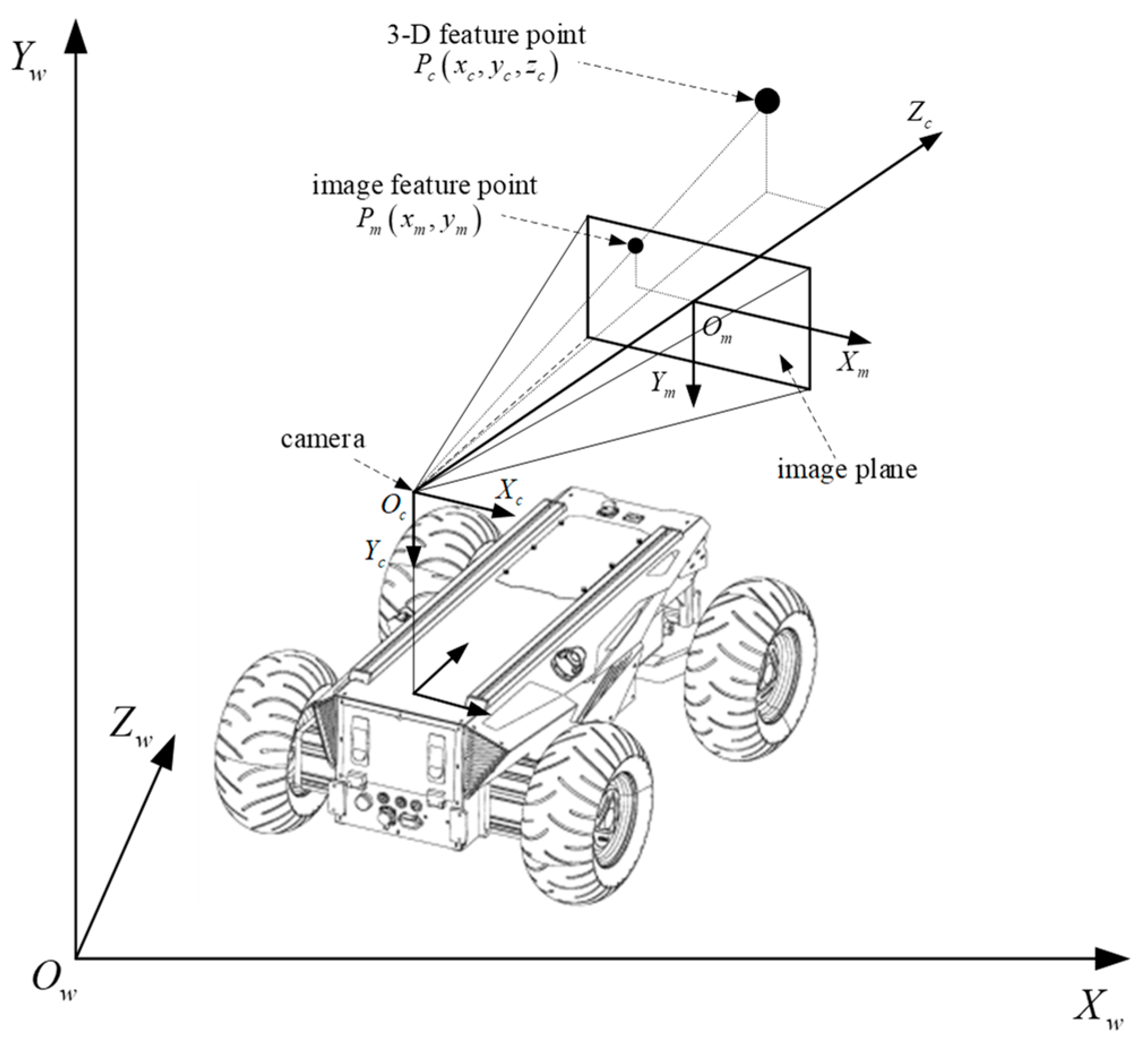
2.2. Model of IBVS System

It is necessary to establish suitable expressions to change the coordinates of a three-dimensional (3D) space into a two-dimensional (2D) plane. The relationship between image change and mobile robot motion of the calibration-free servo system can be modeled directly from the known image information, i.e., the image Jacobi matrix can be obtained to establish the transformation between the 3D space and 2D plane. This method could reduce the amount of coordinate conversion and system calculations, and does not need to calculate the internal and external parameters of the camera. Thus, it can avoid the impact of errors generated during the calibration process. It is defined as
f ˙ = J r r r ˙
where f = f 1 , f 2 , , f m T is the image feature point coordinates, f ˙ is the velocity of the image feature point change, r = r 1 , r 2 , , r n T is the mobile robot position, r ˙ is the velocity of the mobile robot position change, and J r r is the image Jacobi matrix.
Figure 2 is the camera imaging principle. O w X w Y w Z w is the world coordinate system. O c X c Y c Z c is the camera coordinate system. O m X m Y m is the image coordinate system.
In Figure 2, the coordinate point P of the camera coordinate system is P c = x c , y c , z c , and P of the plane image coordinate system is P m x m , y m . According to the camera imaging principle, we have
x m = λ d x x c z c + x m 0 y m = λ d y y c z c + y m 0
where λ is the camera focal length, x m 0 , y m 0 is the image plane origin, and d x , d y are the physical sizes of a unit pixel on the horizontal and vertical axes, respectively. Taking the derivative of (10),
x ˙ m = λ d x x ˙ c z c x c z ˙ c z c 2 y ˙ m = λ d y y ˙ c z c y c z ˙ c z c 2
Let v = v x , v y , v z T be the linear velocity of the mobile robot, and w = w x , w y , w z T be the angular velocity of the mobile robot. The velocity of a point in space with respect to the camera coordinate system is
P ˙ c = w × P c v
According to (12),
x ˙ c = v x w y z c + w z y c y ˙ c = v y w z x c + w x z c z ˙ c = v x w x y c + w y x c
Then we have
x ˙ m y ˙ m = λ z c 0 x m z c x m y m λ λ 2 + x m 2 λ y m 0 λ z c y m z c λ 2 + y m 2 λ x m y m λ x m v x v y v z w x w y w z
where the velocity of the image feature point change is f ˙ = x ˙ m , y ˙ m T , the velocity of the mobile robot position change is r ˙ = v x , v y , v z , w x , w y , w z T , and the image Jacobi matrix is
J r = λ z c 0 x m z c x m y m λ λ 2 + x m 2 λ y m 0 λ z c y m z c λ 2 + y m 2 λ x m y m λ x m
Combining (14) with the kinematic model of the mobile robot, the velocity of the restricted mobile robot’s position change is
r ˙ = X ˙ r , Y ˙ r , 0 , 0 , 0 , φ ˙ T
The relationship between the change speed of 2D image feature points and the mobile robot control quantity can be obtained:
f ˙ = x ˙ m , y ˙ m T = J r r ˙ = J r cos φ v r , sin φ v r , 0 , 0 , 0 , w T
where f ˙ is the velocity of the 2D image feature point change, and v r , w are the linear and angular velocity control quantities of the mobile robot, respectively.

3. Controller Design

Figure 3 is the control block diagram of the IBVS-PF-HMPC system. X * , Y * , φ * are the desired positions of the mobile robot, X , Y , φ are the predicted positions correction of the mobile robot, x m * , y m * are the desired coordinate inputs of the image feature points, x m , y m are the predicted correction outputs of the image coordinate points, e r is the state deviation input, e c is the predicted deviation, y s is the actual value output, y c is the model prediction output, and v r , w are the control quantities.

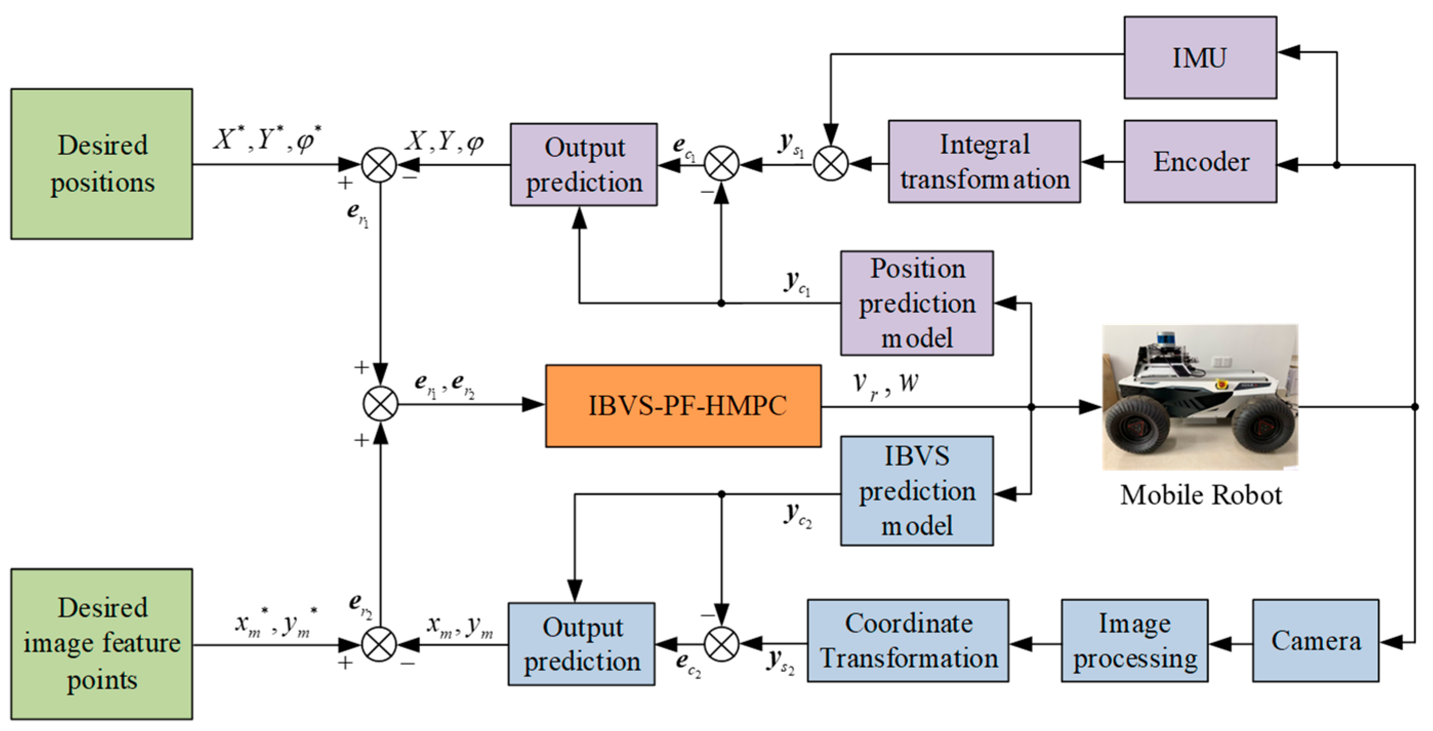
3.1. Design of the Hybrid Model Predictive Control Based on IBVS

Model predictive control (MPC) is an iterative optimization technique. The optimal control volume prediction sequence is obtained by substituting the current state measured or estimated at each sampling time into the optimization function. And the first of these control quantities is taken as the control input at the current moment.
The general form of the nonlinear system can be abstracted as
x ˙ = f x , u
where x is the state, x ˙ is the rate of the state change, u is the control input.
Let the current moment be k , and the control period be T . (18) is discretized by Euler’s method:
x k + 1 | k = x k | k + T x ˙ k | k = x k | k + T f x k | k , u k | k
in which,
x k | k , k = 1 , 2 , , N p u k | k , k = 1 , 2 , , N c
where N p and N c represent the prediction range N p 1 and the control range 0 N c N p . The state quantities in the prediction time domain are
x k + 1 | k = x k | k + T f x k | k , u k + 1 | k x k + N c + 1 | k = x k + N c | k + T f x k + N c | k , u k + N c | k x k + N p | k = x k + N p 1 | k + T f x k + N p 1 | k , u k + N c | k
Define the state quantity deviation as e k | k = x k | k x k | k * , in which, x k | k is the current state, x k | k * is the desired state. Then, the optimization function of MPC is defined as follows:
J e , u = i = 1 N p e k + i | k Q 2 + i = 0 N c 1 u k + i | k R 2
where e k + i | k represents the state deviation of k + i , which is predicted at the time of k , u k + i | k represents the input deviation of k + i , which is predicted at the time of, and Q and R are the weighting matrices of the deviation of the state quantity and the input quantity, respectively.
Rewrite both the state and input quantities as increments:
E k + i | k = e k + i | k e k + i 1 | k U k + i | k = u k + i | k u k + i 1 | k
Combining (8) and (17), define the mobile robot’s position as x 1 = X , Y , φ T , the image feature point coordinate as x 2 = x m , y m T , and the control quantity of the mobile robot as u = v r , w T . The deviation in (22) can be divided into two parts: the deviation of the position and the deviation of the feature points.
e 1 k | k = x 1 k | k x 1 k | k * e 2 k | k = x 2 k | k x 2 k | k *
Then, the hybrid model predictive control based on IBVS (IBVS-HMPC) can be obtained:
min   J E 1 , E 2 , U = i = 1 N p E 1 k + i | k Q 1 2 + i = 1 N p E 2 k + i | k Q 2 2 + i = 0 N c 1 U k + i | k R 2
s . t . u min u k u max U min U k U max
where u min , u max , U min U max are the minimum and maximum values of control quantity and control increment, respectively.

3.2. Design of the IBVS-PF-HMPC

The emergency braking performance of the mobile robot needs to be guaranteed when the image feature points are massively obscured by obstacles in dynamic scenes. So it is necessary to introduce the penalty factor into the above IBVS-HMPC.
The number of feature points in the image is N , and the i th feature points ζ i . The number of obstacle-obscuring feature points is
s u m = i = 0 N ζ i
Introducing the penalty factor C , the penalty term C i = 0 N ζ i of the optimization function with respect to the loss of feature points is obtained from C = i = 0 N ζ i N . Then, (25) can be rewritten as
min   J E 1 , E 2 , U = i = 1 N p E 1 k + i | k Q 1 2 + i = 1 N p E 2 k + i | k Q 2 2 + i = 0 N c 1 U k + i | k R 2 + C i = 0 N ζ i
s . t . u min u k u max U min U k U max
The sequence of control increment predictions for the current moment can be obtained:
U * = U k | k , U k + 1 | k , , U k + N c | k T
The first element is taken as the actual control increment acting on the controlled system at the current moment:
u ( k | k ) = u ( k 1 | k ) + U ( k | k )
The predicted state quantity is obtained by modifying the actual state quantity and transmitted to the next control cycle for optimization and a solution. Repeat the above process to complete rolling optimization within the control time domain and the automatic parking trajectory tracking control for mobile robots is realized.
When the feature points are massively lost, s u m = i = 0 N ζ i is large, and the optimization function (28) has no solution. Thus, the control input is 0, and the emergency braking of the mobile robot in dynamic obstacle scenarios could be realized.
The steps of the proposed control methodology of IBVS-PF-HMPC are shown in Table 1.

4. Simulation Results

In order to verify the effectiveness of the proposed control method, four groups of comparison experiments based on MATLAB are conducted. According to the motion characteristics of the mobile robot, the system limitations during simulation tests are as follows: the line velocity limitation of the mobile robot is 1   m / s , 1   m / s ; the angular velocity limitation of the mobile robot is 0.2   rad / s , 0.2   rad / s ; the linear velocity increment limitation of the mobile robot is 0.1   m / s , 0.1   m / s ; and the angular velocity increment limitation of the mobile robot is 0.02   rad / s , 0.02   rad / s . The physical parameters of the mobile robot and the parameters of the IBVS-PF-HMPC when it reaches steady-state are given in Table 2. The control quantity predictive sequence is used as an optimization variable in the optimal control process of the automatic parking for mobile robots. The optimization criterion is minimizing the respective sums of the position deviation increment, the image feature point deviation increment and the control quantity predictive sequence. Then, the controller could take into account the state quantity output and control quantity input to ensure the good trajectory tracking control of the constrained mobile robot in the automatic parking process.

4.1. Parking Trajectory Planning

Both the arc-tangent function curve and the higher polynomial curve fit better with the automatic parking trajectory. Considering that the higher polynomial with more than four times is more complicated in the calculation, therefore, the arc-tangent function is selected design the reference trajectory in Figure 4, and the defined parallel parking trajectory model is as follows:
y = a arctan b x + c + d
where a = 1.024 , b = 1.143 , c = 2.618 , d = 1.227 .

4.2. Stability Performance

In the first simulation scenario, the proposed hybrid model predictive control with a penalty factor based on IBVS (IBVS-PF-HMPC) is compared with the traditional IBVS control (T-IBVSC), to verify the tracking performance under the image feature point loss scenario. Figure 5 and Figure 6 exhibit the trajectory tracking curves of the mobile robot under the control of T-IBVSC and IBVS-PF-HMPC, respectively.
As shown in Figure 5 and Figure 6, T-IBVSC and IBVS-PF-HMPC could maintain good trajectory tracking control until 2.5 m in the X axis. But the T-IBVSC fails to complete trajectory tracking control at 2.5 m due to the sudden increase in the control quantity w , which causes the image feature points to be lost in the field of view and is out of control in the following time.

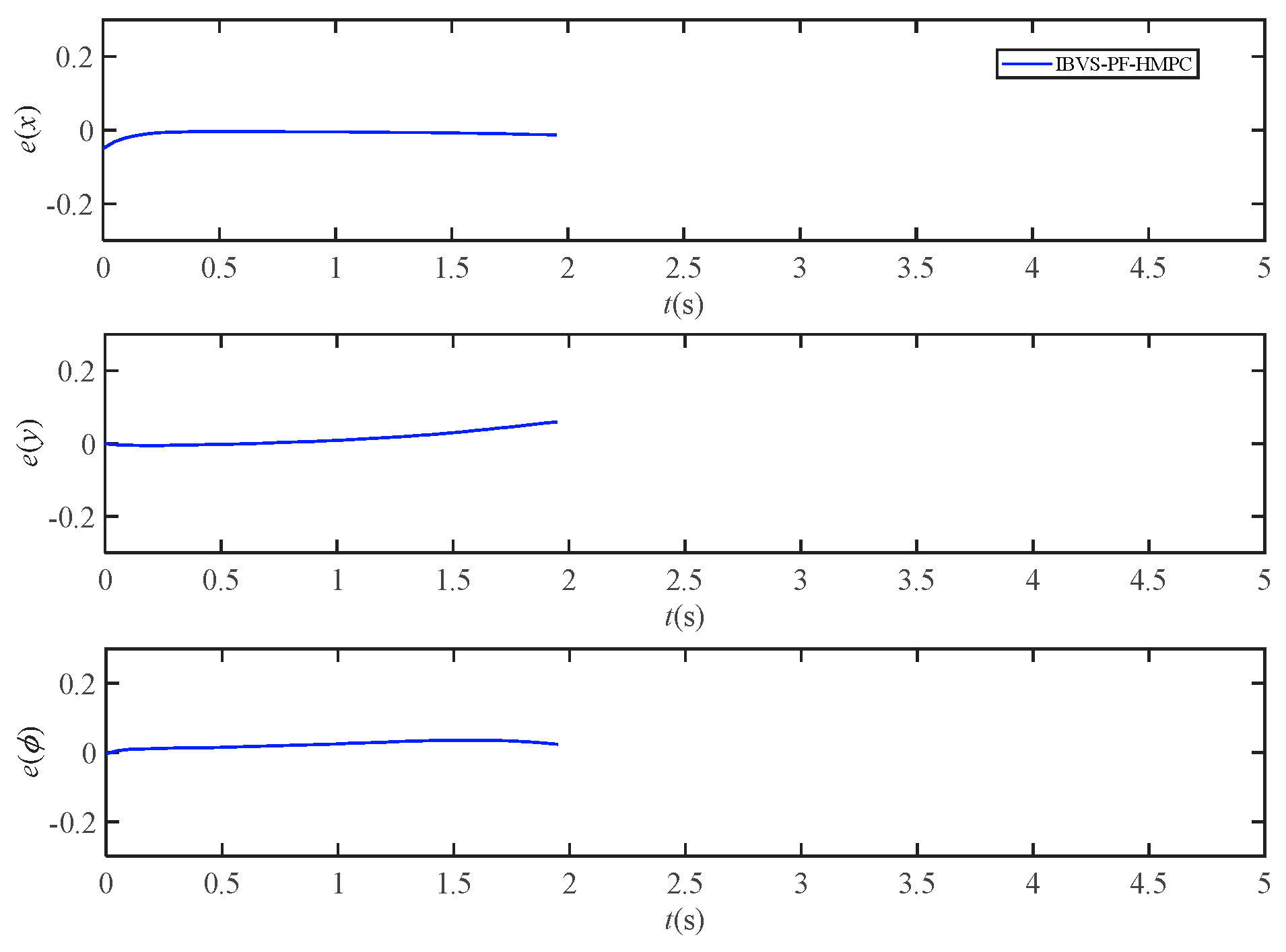
4.3. Tracking Accuracy Performance

In the second simulation scenario, the proposed IBVS-PF-HMPC is compared with the model predictive control based on IBVS (IBVS-MPC), to verify the tracking performance under the image feature point loss scenario. Although the IBVS-MPC has a constraint limit on the image feature points, it only considers the image feature deviation without considering the position deviation of the mobile robot at the same time. Then, the image feature points are lost intermittently by adding interference. Figure 7 is the trajectory tracking curves of the mobile robot under the control of IBVS-MPC and IBVS-PF-HMPC. Figure 8 and Figure 9 exhibit the control quantity and the position deviation of the mobile robot under the control of IBVS-MPC and IBVS-PF-HMPC, respectively. And the root means square errors (RMSE) of the deviation of each component of the mobile robot position under the control of IBVS-MPC and IBVS-PF-HMPC are shown in Table 3.
As shown in Figure 7, the maximum tracking error of IBVS-PF-HMPC is 2.3 × 10 2 m, and the maximum tracking error of IBVS-MPC is 3.9 × 10 2 m. The proposed IBVS-PF-HMPC could achieve higher trajectory tracking accuracy than the IBVS-MPC. This is due to the fact that the proposed controller considers both image feature point deviation and mobile robot position deviation. When the image feature points are intermittently lost due to external perturbations, the position deviation still acts on the mobile robot controller.
As shown in Figure 8 and Figure 9, the average values of each position deviation of the mobile robot are 1.04 × 10 2 m, 2.41 × 10 2 m and 2.15 × 10 2 rad under the control of IBVS-PF-HMPC, and the average values of each position deviation of the mobile robot are 1.62 × 10 2 m, 6.85 × 10 2 m and 3.15 × 10 2 rad under the control of IBVS-MPC. It shows that the position tracking accuracy of IBVS-PF-HMPC is 35.80%, 64.82% and 31.75% higher than that of IBVS-MPC, respectively. This is due to the loss of image feature points, as the control quantity of IBVS-MPC jittered more significantly and reached the limit constraint several times.
As shown in Table 3, the RMSE of the deviation of each component of the mobile robot position under the IBVS-PF-HMPC is smaller than the RMSE of IBVS-MPC. Therefore, the proposed control algorithm owns better trajectory tracking performance in the case of image feature point loss.

4.4. Real-Time Performance

In the third simulation scenario, the proposed IBVS-PF-HMPC is compared with the IBVS-PF-HMPC without increment (NI-IBVS-PF-HMPC), to verify the real-time and tracking accuracy of the mobile robot. Figure 10 is the trajectory tracking curves of the mobile robot under the control of NI-IBVS-PF-HMPC and IBVS-PF-HMPC. Figure 11 and Figure 12 exhibit the control quantity and the position deviation of the mobile robot under the control of NI-IBVS-PF-HMPC and IBVS-PF-HMPC, respectively. And the RMSE of the deviation of each component of the mobile robot position under the control of NI-IBVS-PF-HMPC and IBVS-PF-HMPC are shown in Table 4.
As shown in Figure 10, the maximum tracking error of IBVS-PF-HMPC is 2.3 × 10 2 m, and the maximum tracking error of NI-IBVS-PF-HMPC is 9.5 × 10 2 m. The simulation results show that the proposed control method owns better tracking accuracy.
As shown in Figure 11 and Figure 12, the average values of each position deviation of the mobile robot are 1.04 × 10 2 m, 2.41 × 10 2 m and 2.15 × 10 2 rad under the control of BVS-PF-HMPC, and the average values of each position deviation of the mobile robot are 2.91 × 10 2 m, 9.22 × 10 2 m and 8.62 × 10 2 rad under the control of IBVS-PF-HMPC. It shows that the position tracking accuracy of IBVS-PF-HMPC is 64.26%, 73.86% and 75.06% higher than that of IBVS-MPC, respectively. Meanwhile, it can be seen that the angular velocity w of the mobile robot has a significant lag, which leads to poor real-time when the state and control quantities are not reconfigured. And the position deviation of NI-IBVS-PF-HMPC is significantly larger than the position deviation of IBVS-PF-HMPC.
As shown in Table 4, the RMSE of the deviation of each component of the mobile robot position under the IBVS-PF-HMPC is smaller than the RMSE of NI-IBVS-PF-HMPC. Therefore, the proposed control algorithm owns better real-time performance and tracking accuracy.

4.5. Emergency Braking Performance

In the fourth simulation scenario, the emergency braking performance of the proposed IBVS-PF-HMPC is verified, by adding more than 10 image feature points that are obscured by dynamic obstacles during the automatic parking of the mobile robot. Figure 13 is the trajectory tracking curve of the mobile robot when the image feature points are massively occluded by obstacles. Figure 14 and Figure 15 are the control quantity and the position deviation when the mobile robot is obscured by the dynamic obstacle, respectively.
As shown in Figure 13, when the image feature points are massively occluded by obstacles, the mobile robot control system no longer tracks the desired trajectory. It can be seen from Figure 14 and Figure 15 that the control quantities tend to 0 when s u m = i = 0 N ζ i = 10 ,   C = i = 0 N ζ i N = 0.5 . Consequently, the emergency braking of the mobile robot in the dynamic obstacle scene could be realized in time.

5. Conclusions

For the constrained mobile robot automatic parking system, the IBVS-PF-HMPC is proposed, to address the problem of feature point loss and emergency braking in dynamic obstacle scenarios caused by excessive target bias gain when using traditional IBVS control methods. The main conclusions are as follows:
(1)
The IBVS-based incremental model predictive control algorithm is designed. The traditional IBVS control is transformed into an optimization problem with constraints in the finite time domain, by defining the optimization function based on the mobile robot’s positional deviation and image feature point deviation, while using the actuator saturation and speed limit as constraints. Then, the accuracy and real-time of the mobile robot tracking control during automatic parking is improved simultaneously.
(2)
The convex optimization function with penalty factor is defined. Then, the IBVS-PF-HMPC is proposed, to guarantee the emergency braking performance of the mobile robot automatic parking when the image feature points are massively obstructed by obstacles in dynamic scenes.
(3)
Several simulation comparisons further verify the correctness and effectiveness of the proposed IBVS-PF-HMPC.

Author Contributions

Conceptualization, H.G., Q.Q. and J.M.; software, Q.Q. and H.G.; validation, J.M. and H.G.; formal analysis, H.G. and J.M.; investigation, J.M. and Y.H.; data curation, H.G. and Q.Q.; writing—original draft preparation, H.G.; writing—review and editing, H.G. and X.S.; supervision, Q.Q.; project administration, J.M.; funding acquisition, Q.Q. and J.M. All authors have read and agreed to the published version of the manuscript.

Funding

This work is supported in part by the National Natural Science Foundation of China under Grant No. 52177051, the Natural Science Research Program of Jiangsu Colleges and Universities under Grant No. 20KJA470002, the Excellent Teaching Team of “Qinglan Project” of Jiangsu Colleges and Universities and the Talent Introduction Startup Fund of Nantong University under Grant No. 135437612076.

Data Availability Statement

The data used to support the findings of this study are available from the corresponding author upon request.

Conflicts of Interest

The authors declare no conflict of interest.

References

  1. Yu, Y. Smart parking system based on edge-cloud-dew computing architecture. Electronics 2023, 12, 2801. [Google Scholar] [CrossRef]
  2. Chen, W.; Xu, T.; Liu, J.; Wang, M.; Zhao, D. Picking robot visual servo control based on modified fuzzy neural network sliding mode algorithms. Electronics 2019, 8, 605. [Google Scholar] [CrossRef] [Green Version]
  3. He, S.; Xu, Y.; Guan, Y.; Li, D.; Xi, Y. Synthetic robust model predictive control with input mapping for constrained visual servoing. IEEE Trans. Ind. Electron. 2023, 70, 9270–9280. [Google Scholar] [CrossRef]
  4. Xu, D. A tutorial for monocular visual servoing. Acta Automatica Sin. 2018, 44, 1729–1746. [Google Scholar]
  5. Zhong, H.; Wang, Y.; Miao, Z.; Li, L.; Fan, S.; Zhang, H. A homography-based visual servo control approach for an underactuated unmanned aerial vehicle in GPS-denied environments. IEEE T. Intell. Veh. 2023, 8, 1119–1129. [Google Scholar] [CrossRef]
  6. Chan, W.; Srigrarom, S. Image-based visual-servoing for air-to-air drone tracking & following with model predictive control. In Proceedings of the 2023 SICE International Symposium on Control Systems (SICE ISCS), Kusatsu, Japan, 9–11 March 2023. [Google Scholar]
  7. Aaron, M.; Marwen, J.; Peter, C. Image-based visual servoing with unknown point feature correspondence. IEEE Robot. Autom. Lett. 2017, 2, 601–607. [Google Scholar]
  8. Becerra, H.; Lopez-Nicolas, G.; Saguees, C. A sliding-mode-control law for mobile robots based on epipolar visual servoing from three views. IEEE Trans. Robot. 2011, 27, 175–183. [Google Scholar] [CrossRef]
  9. Wang, F.; Qin, Y.; Guo, F.; Ren, B.; John, T. Adaptive visually servoed tracking control for wheeled mobile robot with uncertain model parameters in complex environment. Complexity 2020, 3, 8836468. [Google Scholar] [CrossRef]
  10. Sunhyo, K.; Se-Young, O. Hybrid position and image based visual servoing for mobile robots. J. Intell. Fuzzy Syst. 2007, 18, 73–82. [Google Scholar]
  11. Li, B.; Fang, Y.; Hu, G.; Zhang, X. Model-free unified tracking and regulation visual servoing of wheeled mobile robots. IEEE Trans. Control Syst. Technol. 2016, 24, 1328–1339. [Google Scholar] [CrossRef]
  12. Fang, Y.; Liu, X.; Zhang, X. Adaptive active visual servoing of nonholonomic mobile robots. IEEE Trans. Ind. Electron. 2012, 59, 486–497. [Google Scholar] [CrossRef]
  13. Zhang, K.; Chen, J.; Li, Y.; Gao, Y. Unified visual servoing tracking and regulation of wheeled mobile robots with an uncalibrated camera. IEEE-ASME Trans. Mechatron. 2018, 23, 1728–1739. [Google Scholar] [CrossRef]
  14. Yuan, W.; Liu, Y.; Su, C.; Zhao, F. Whole-body control of an autonomous mobile manipulator using model predictive control and adaptive fuzzy technique. IEEE Trans. Fuzzy Syst. 2023, 31, 799–809. [Google Scholar] [CrossRef]
  15. Kang, E.; Qiao, H.; Chen, Z.; Gao, J. Tracking of uncertain robotic manipulators using event-triggered model predictive control with learning terminal cost. IEEE Trans. Autom. Sci. Eng. 2022, 19, 2801–2815. [Google Scholar] [CrossRef]
  16. Heshmati-alamdari, S.; Karavas, G.; Eqtami, A.; Drossakis, M.; Kyriakopoulos, K. Robustness analysis of model predictive control for constrained image-based visual servoing. In Proceedings of the 2014 IEEE International Conference on Robotics and Automation (ICRA), Hong Kong, China, 31 May–7 June 2014. [Google Scholar]
  17. Bai, H.; Gao, J.; Sun, X.; Yan, W. Model predictive visual trajectory-tracking control of wheeled mobile robots. In Proceedings of the 2019 IEEE 28th International Symposium on Industrial Electronics (ISIE), Vancouver, BC, Canada, 12–14 June 2019. [Google Scholar]
  18. Heshmati-alamdari, S.; Karras, G.; Eqtami, A.; Kyriakopoulos, K. A robust self-triggered image based visual servoing model predictive control scheme for small autonomous robots. In Proceedings of the 2015 IEEE/RSJ International Conference on Intelligent Robots and Systems (IROS), Hamburg, Germany, 28 September–2 October 2015. [Google Scholar]
  19. Li, Z.; Yang, C.; Su, C.; Deng, J.; Zhang, W. Vision-based model predictive control for steering of a nonholonomic mobile robot. IEEE Trans. Control Syst. Technol. 2016, 24, 553–564. [Google Scholar] [CrossRef]
  20. Chi, X.; Liu, Z.; Huang, J.; Hong, F.; Su, H. Optimization-based motion planning for autonomous parking considering dynamic obstacle: A hierarchical framework. In Proceedings of the 2022 34th Chinese Control and Decision Conference (CCDC), Hefei, China, 15–17 August 2022. [Google Scholar]
  21. Yu, R.; Guo, H.; Chen, H. Predictive obstacle-avoidance control for autonomous vehicle information and control. Inf. Contrl. 2015, 44, 117–124. [Google Scholar]
Figure 1. Motion model of the mobile robot.
Electronics 12 03186 g001
Figure 2. The camera imaging principle.
Electronics 12 03186 g002
Figure 3. The control block diagram of IBVS-PF-HMPC system.
Electronics 12 03186 g003
Figure 4. The reference trajectory for mobile robot automatic parking.
Electronics 12 03186 g004
Figure 5. The tracking curves of the mobile robot under the T-IBVSC.
Electronics 12 03186 g005
Figure 6. The tracking curves of the mobile robot under the IBVS-PF-HMPC.
Electronics 12 03186 g006
Figure 7. The tracking curves of the mobile robot under the IBVS-MPC and IBVS-PF-HMPC.
Electronics 12 03186 g007
Figure 8. The control quantity under the control of IBVS-MPC and IBVS-PF-HMPC.
Electronics 12 03186 g008
Figure 9. The position deviation under the control of IBVS-MPC and IBVS-PF-HMPC.
Electronics 12 03186 g009
Figure 10. The tracking curves of the mobile robot under the NI-IBVS-PF-HMPC and IBVS-PF-HMPC.
Electronics 12 03186 g010
Figure 11. The control quantity under the control of NI-IBVS-PF-HMPC and IBVS-PF-HMPC.
Electronics 12 03186 g011
Figure 12. The position deviation under the control of NI-IBVS-PF-HMPC and IBVS-PF-HMPC.
Electronics 12 03186 g012
Figure 13. The trajectory tracking curves of the mobile robot facing the massive obstacles.
Electronics 12 03186 g013
Figure 14. The control quantity facing the massive obstacles.
Electronics 12 03186 g014
Figure 15. The position deviation facing the massive obstacles.
Electronics 12 03186 g015
Table 1. The steps of the proposed control methodology of IBVS-PF-HMPC.
StepsDescription
1Defining an automatic parking trajectories based on mobile robot position and parking space coordinate information;
2Capturing the vehicle position image feature points of the camera and calculating the position deviation and image feature point deviation;
3Reconstructing the incremental position deviation and image feature point deviation and substituting them into the IBVS-PF-HMPC;
4Obtaining the control increment prediction sequence at the current moment from IBVS-PF-HMPC;
5Taking the first element of the control increment predictive sequence as the actual control increment at the current moment, and obtaining the model prediction outputs of the state variables from the mobile robot kinematics predictive model (8) and the IBVS predictive model (17);
6Modifying model predicted outputs by actual state variables;
7Substituting the modified model prediction outputs of the state variables into the IBVS-PF-HMPC, and repeating Steps 3–7.
Table 2. The parameters of the mobile robot and IBVS-PF-HMPC.
ParametersValueParametersValue
Wheelbase L / m 1Feature point error increment penalty weight matrix Q 2 1 0 0 1
Control period T / ms 50Control incremental error weight matrix R 1 0 0 1
Predicted step-size N p 20Image feature points N 20
Control step-size N c 20Control incremental constraint U min , U max 0.1 0.1 0.02 0.02
Position error increment penalty weight matrix Q 1 10 0 0 0 10 0 0 0 50 Control constraint u min , u max 1 1 0.2 0.2
Table 3. The RMSE of the deviation of each component of the mobile robot position under the control of IBVS-MPC and IBVS-PF-HMPC.
IBVS-PF-HMPCIBVS-MPC
RMSE e x 1.26 × 10 2 2.94 × 10 2
RMSE e y 3.31 × 10 2 9.84 × 10 2
RMSE e φ 2.47 × 10 2 4.98 × 10 2
Table 4. The RMSE of the deviation of each component of the mobile robot position under the control of NI-IBVS-PF-HMPC and IBVS-PF-HMPC.
IBVS-PF-HMPCNI-IBVS-PF-HMPC
RMSE e x 1.26 × 10 2 3.77 × 10 2
RMSE e y 3.31 × 10 2 11.30 × 10 2
RMSE e φ 2.47 × 10 2 10.56 × 10 2
Disclaimer/Publisher’s Note: The statements, opinions and data contained in all publications are solely those of the individual author(s) and contributor(s) and not of MDPI and/or the editor(s). MDPI and/or the editor(s) disclaim responsibility for any injury to people or property resulting from any ideas, methods, instructions or products referred to in the content.

