1. Introduction
The automobile industry is currently witnessing a significant shift towards automated driving and assisted driving. The safe and efficient automated or assisted driving of intelligent vehicles is heavily dependent on environmental perception technology, which serves as a fundamental guarantee. In the field of automated driving, millimeter-wave radar has become an important element in the environmental perception system. Its superior characteristics—such as its all-day, all-weather, all-region utility; its high-performance; and its low-cost [
1,
2,
3,
4,
5,
6,
7,
8]—make it an ideal choice for use in various automated driving applications, including blind spot detection, adaptive cruise control, lane change assistance, collision warning and automatic parking. Therefore, automotive millimeter-wave radar possesses significant application value in the field of environmental perception and in the information interaction of automated vehicles. Beyond that, millimeter-wave radar has been widely used in the road traffic speeding enforcement [
9] and rail traffic speed surveillance [
10].
Presently, commercial automotive millimeter-wave radars for the environmental perception of automated vehicles commonly operate in frequency bands of around 24 GHz and 77 GHz. The 24 GHz millimeter-wave radar has a bandwidth of 250 MHz ranging from 24 GHz to a maximum of 24.25 GHz in China. In the field of automated driving, 24 GHz millimeter-wave radar is usually applied to short-range measurement scenarios, such as surrounding environmental perception, blind spot detection, automatic parking, lane change assistance, and so on. With the increasing popularity of automated vehicle technology, however, the limitations of the 24 GHz millimeter-wave radar used for detection have become more apparent. In particular, the narrow bandwidth of the 24 GHz millimeter-wave radar technology constrains its ability to provide high-precision and omni-directional detection. Therefore, there is a need to explore alternative technologies that can better satisfy the requirements of automated vehicle detection. The range resolution and accuracy of 77 GHz millimeter-wave radar are superior to those of the 24 GHz millimeter-wave radar due to the wider operating bandwidth of the former. Specifically, 77 GHz millimeter-wave radar operates within the frequency range of (76~77) GHz with a bandwidth of 1 GHz, and up to (76~79) GHz with a bandwidth of 3 GHz in China. Therefore, the 77 GHz millimeter-wave radar is widely applicable in medium- and long-range measurements, which includes automatic tracking, adaptive cruise, collision warning, emergency braking, and so on [
11,
12,
13,
14]. As 24 GHz and 77 GHz millimeter-wave radars can be respectively installed on different types of automated vehicles, a compromise between accurate sensing and cost-effectiveness can be made when selecting appropriate sensors. In addition, with the development of system chip integration technology, automotive millimeter-wave radars with smaller size and higher integration have become the mainstream environmental perception sensors in the automobile industry.
The accurate assessment and adequate testing of the operational effectiveness of automotive millimeter-wave radar in actual applications have become important. Therefore, the calibration of automotive millimeter-wave radar objective kinematic parameters has emerged as a critical endeavor. Nowadays, automotive millimeter-wave radars are mostly tested in the field by the real vehicle methods operated both in the controlled proving ground and in actual traffic scenarios [
15,
16,
17,
18,
19,
20]. The field test in the controlled proving ground is usually operated on a closed road for the sake of safety. Here, a real vehicle equipped with a millimeter-wave radar travels under test conditions through a road section with preset simulated traffic scenarios at specified speed points. Then, the automotive millimeter-wave radar under examination can measure the kinematic parameters and obtain other information about the surrounding objects in the simulated traffic scenarios. In this case, there is a high cost incurred by the provision of a large site and the creation of various test scenarios that ensure the safety and effectiveness of the controlled proving ground testing. Field tests operated in actual traffic scenarios are conducted on the normal open roads. The millimeter-wave radars under examination, together with other sensors for environmental perception, are integrated into the real vehicle and measure the speed, range, and angle of the surrounding vehicles of the real traffic scenarios on an actual road. Real vehicle testing methods with high authenticity have the disadvantages of working under uncontrollable scenarios with poor repeatability, low exposure rate of dangerous scenarios, and poor safety [
21]. Furthermore, owing to the absence of reference values for comparison and the lack of measurement repeatability for traceability, it is difficult to comprehensively calibrate and evaluate the measured kinematic parameters of the automotive millimeter-wave radar using the present real vehicle testing methods.
Du et al. proposed a simulated speed calibration method for 24 GHz road traffic millimeter-wave radar with target position determination [
9] as well as a speed calibration method for 24 GHz rail traffic Doppler radar [
10]. However, the above two calibration methods are only applicable for the speed calibration of single frequency continuous wave millimeter-wave radars, which are not applicable for 24 GHz and 77 GHz automotive millimeter-wave radars. Xu et al. proposed a preliminary calibration principle for 77 GHz frequency modulation continuous wave (FMCW) millimeter-wave radar [
12], and then proposed an idea to extend the above preliminary calibration principle to 24 GHz and 77 GHz automotive FMCW millimeter-wave radars [
22]. On the basis of a previous study on various calibration methods for millimeter-wave radars, we proposed a speed and range calibration method for automotive FMCW millimeter-wave radars, and then established a bi-objective simulation facility for speed and range calibration of 24 GHz and 77 GHz automotive millimeter-wave radars in this paper. The proposed calibration method in this paper can overcome the limitations of the aforementioned approaches and can accurately evaluate the performance of 24 GHz and 77 GHz automotive millimeter-wave radars in measuring the kinematic parameters of environmental perception while maintaining lower costs and higher effectiveness. The established bi-objective simulation facility optimizes the control software to further satisfy the speed and range resolving ability testing requirement of 24 GHz and 77 GHz automotive millimeter-wave radars.
The rest of this paper is organized as follows.
Section 2 introduces the speed, range, and angle measurement principles of automotive millimeter-wave radar.
Section 3 presents the proposed speed and range calibration method for automotive millimeter-wave radars and analyzes the principles of the proposed calibration method in detail.
Section 3 also presents the established bi-objective simulation facility for the speed and range calibration of 24 GHz and 77 GHz automotive millimeter-wave radars based on the proposed calibration method and virtual instrument technology, and then presents the design mentality and main technical parameters of the established bi-objective simulation facility. In
Section 4, the speed and range calibration experimental tests are conducted on two 24 GHz and 77 GHz millimeter-wave radar samples to verify the feasibility of the proposed speed and range calibration method. Additionally in
Section 4, the measurement uncertainty evaluation and resolving ability testing results are analyzed to evaluate the calibration performances and accuracy of the established bi-objective simulation facility. Finally, this paper is concluded, and future work is proposed, in
Section 5.
2. Measurement Principle
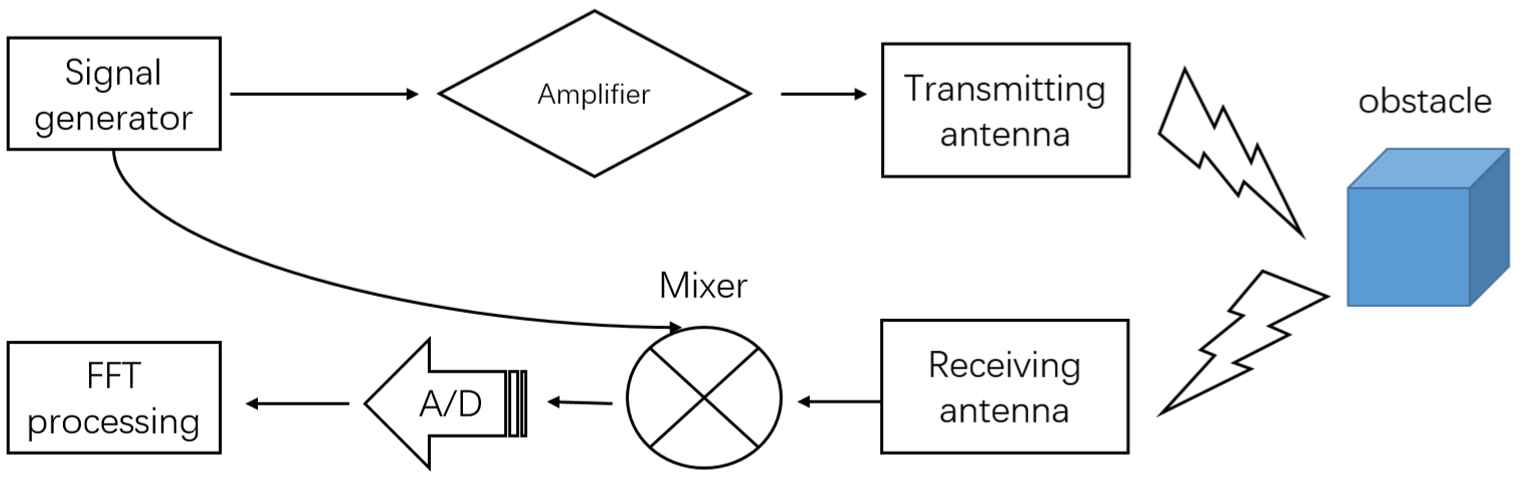
As mentioned above, though the accuracy of the motion parameter measurement of automotive millimeter-wave radar operating at 24 GHz and 77 GHz is different, due to differences in carrier frequency and bandwidth, the principle of measurement is roughly the same. The working process flowchart of automotive millimeter-wave radar is shown in
Figure 1. The millimeter-wave radar generates the detection signal, and then the signal is transmitted to the surrounding environment by the transmitting antenna after being amplified. The echo signal is generated when the detection signal hits an obstacle and is received by the receiving antenna. Then the mixed signal—a mix of the echo and detection signal—is amplified and the A/D converted. Finally, the kinematic information of speed, range and angle of the obstacle is obtained by subjecting the signal to the two-dimensional fast Fourier transform (FFT) algorithm.
2.1. Range Measurement Principle
A 24 GHz or 77 GHz automotive millimeter-wave radar for environmental perception in automated vehicles commonly adopts FMCW technology [
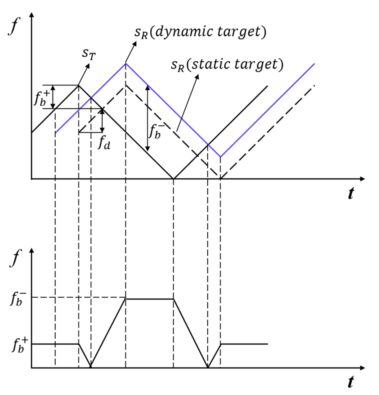
22]. Typically, the frequencies of the automotive millimeter-wave radar with triangular wave modulation are shown in
Figure 2, and the FMCW signal
of the triangular wave is alternately emitted with the pulse repetition interval of
T, where the emitted signal
can be expressed by:
where
is the carrier frequency;
B is the sweep bandwidth;
is the chirp rate and is equal to
;
is a rectangular window function, which means
for
and zero otherwise;
denotes the fast time [
23] and is equal to
, where
denotes the slow time [
23] and
is a natural number.
When the emitted signal encounters an obstacle, it will produce an echo signal, which is received by the receiving antenna. The waveform, amplitude and phase of the echo signal received from the static object are the same as the transmitted signal, but the entire waveform is shifted on the time axis, as shown by the dotted line in the upper image of
Figure 2. The time delay
can be expressed as:
where
represents the range between the radar and the obstacle, and
is the speed of light [
24].
After mixing the received echo signal with the emitted signal, the beat frequency
of the received signal can be obtained as shown in the lower image of
Figure 2. This can be seen from the geometric relationships in
Figure 2:
Based on Equations (2) and (3), the range
R can be calculated by:
Therefore, when the sweep bandwidth B and pulse repetition interval T of the radar-emitted signal remains unchanged, the range value R can be varied by changing the time delay of the echo signal.
2.2. Speed Measurement Principle
The Doppler effect indicates that the frequency of the echo signal becomes higher when the wave source approaches the observer and lower when the wave source is far away from the observer. Similarly, when the object is moving relative to the radar, the frequency of the echo signal changes with the moving speed of the object [
25].
Assuming that the object approaches the radar, the echo signal contains the Doppler shift
, caused by the motion of the object and as shown in
Figure 3. We can thus determine the beat frequencies
and
at the rising and falling edges of the triangular wave, which can be respectively expressed as follows:
where
is the beat frequency when the object is stationary.
Based on the Doppler effect, the Doppler shift
can be expressed as [
22]:
where
is the speed of the moving object.
Based on Equations (5)–(7), the speed
v of the moving object can be calculated by:
Therefore, the speed value v can be varied by changing the Doppler shift .
Based on Equations (4)–(6), the range
R of the moving object can be calculated by:
2.3. Angle Measurement Principle
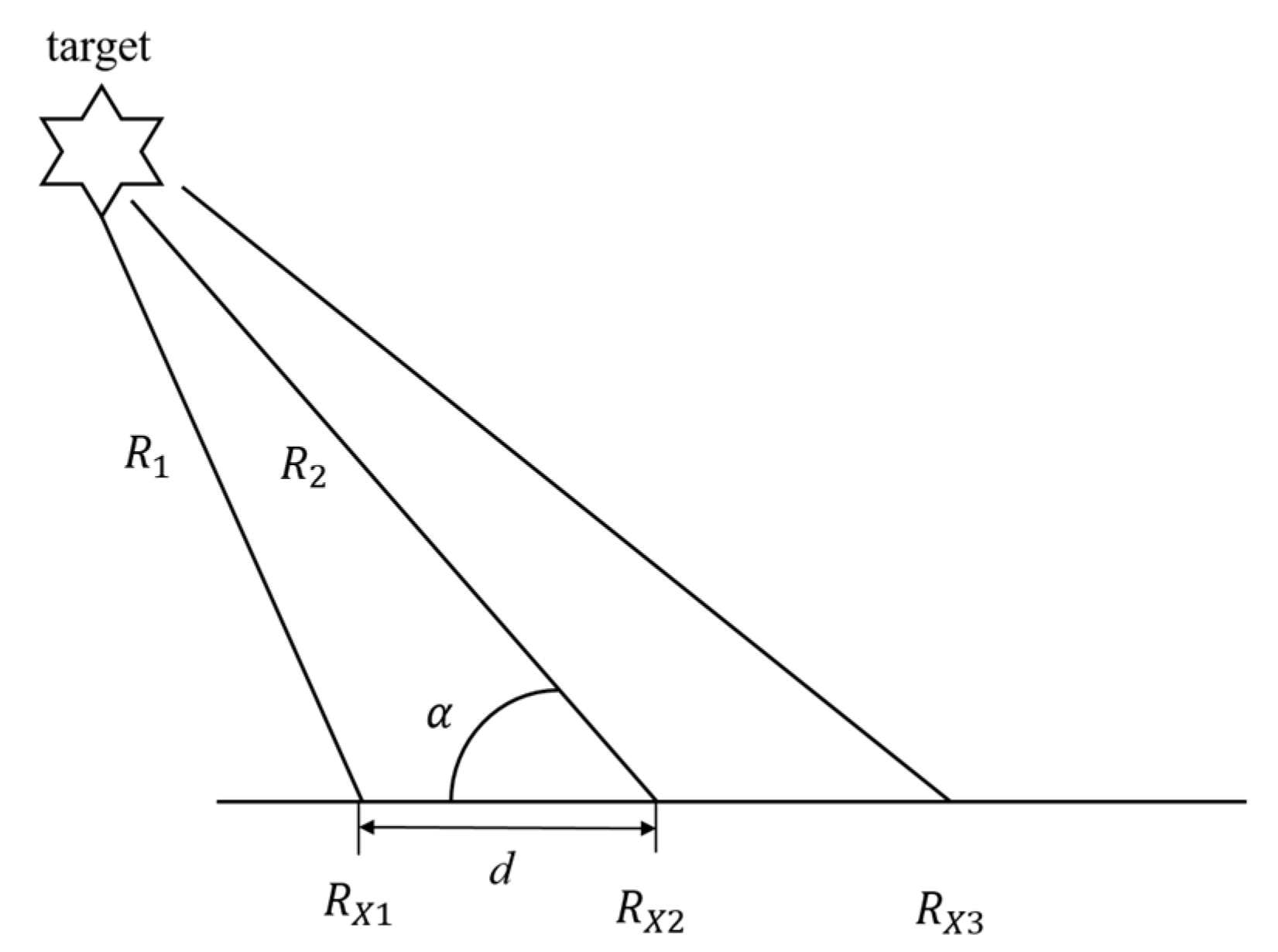
The measurement of angle
is based on the interferometry principle [
26]. According to
Figure 4, when the spacing
d between the adjacent elements of the antenna array is far less than the range
R, the range difference between the adjacent antennas can be calculated by:
When the range difference between the adjacent antennas is less than half of the wavelength
of the emitted signal, the range difference can also be expressed by the phase difference
between the instantaneous phases of the echo received by the adjacent antennas:
According to Equations (10) and (11), the angle
can be calculated by:
Thus, it is feasible to calculate the angle by obtaining the differential phase between adjacent antennas of the radar.
3. Bi-Objective Simulation Facility for Speed and Range Calibration
To ensure the traceability of millimeter-wave radar, a bi-objective simulation facility has been developed based on virtual instrument technology. This simulation facility facilitates the calibration of the range and speed measurement performances of automotive millimeter-wave radars while allowing dual-object simulation. Furthermore, the facility is capable of supporting both 24 GHz and 77 GHz millimeter-wave radars. In contrast to field tests conducted in the controlled proving ground or actual traffic conditions, the simulation facility offers the capability to simulate the echo signal of obstacles in various motion states detected by millimeter-wave radar. This simulation is achieved through hardware and enables performance testing of the radar while reducing costs to a certain extent. Furthermore, the test results obtained from the simulation facility offer greater reliability compared with pure software testing, because the radar’s actual output is used in the simulation, allowing for more accurate and realistic testing of the radar’s performance. In this way, the simulation facility offers a practical and cost-efficient solution to test and calibrate millimeter-wave radar in a laboratory setting with high reliability, aiding the automotive industry in its quest to improve safety standards. The key performance parameters and detailed structure of the simulation facility are shown in
Table 1 and
Figure 5 respectively. The facility can simulate the object approaching or moving away from the radar with a speed of up to 500 km/h. Moreover, the azimuth angle between the simulated object and radar can change from −60° to 60°. Due to the hardware’s performance in terms of data processing speed and signal transmission time, the facility cannot simulate objects within 5.0 m.
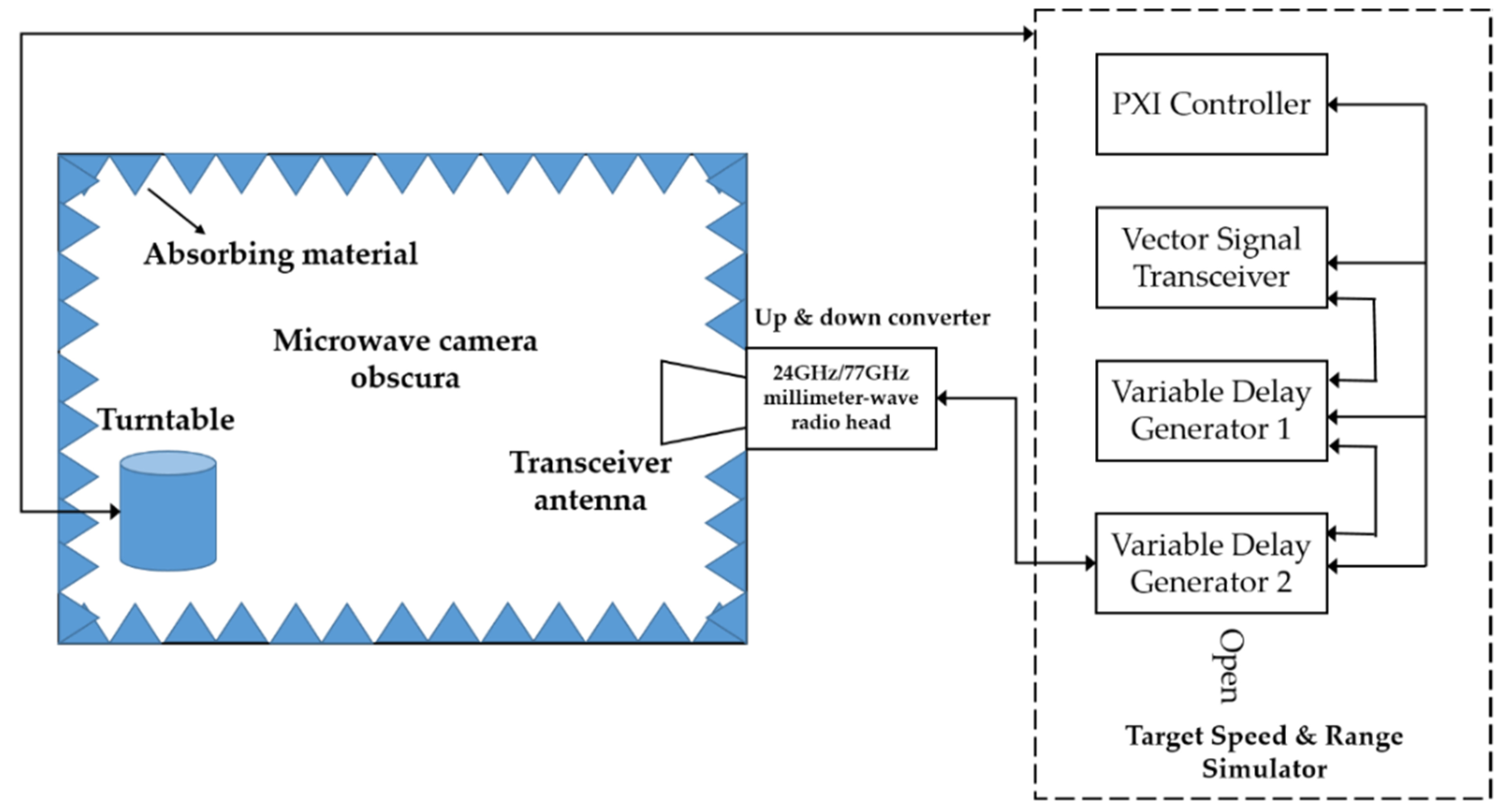
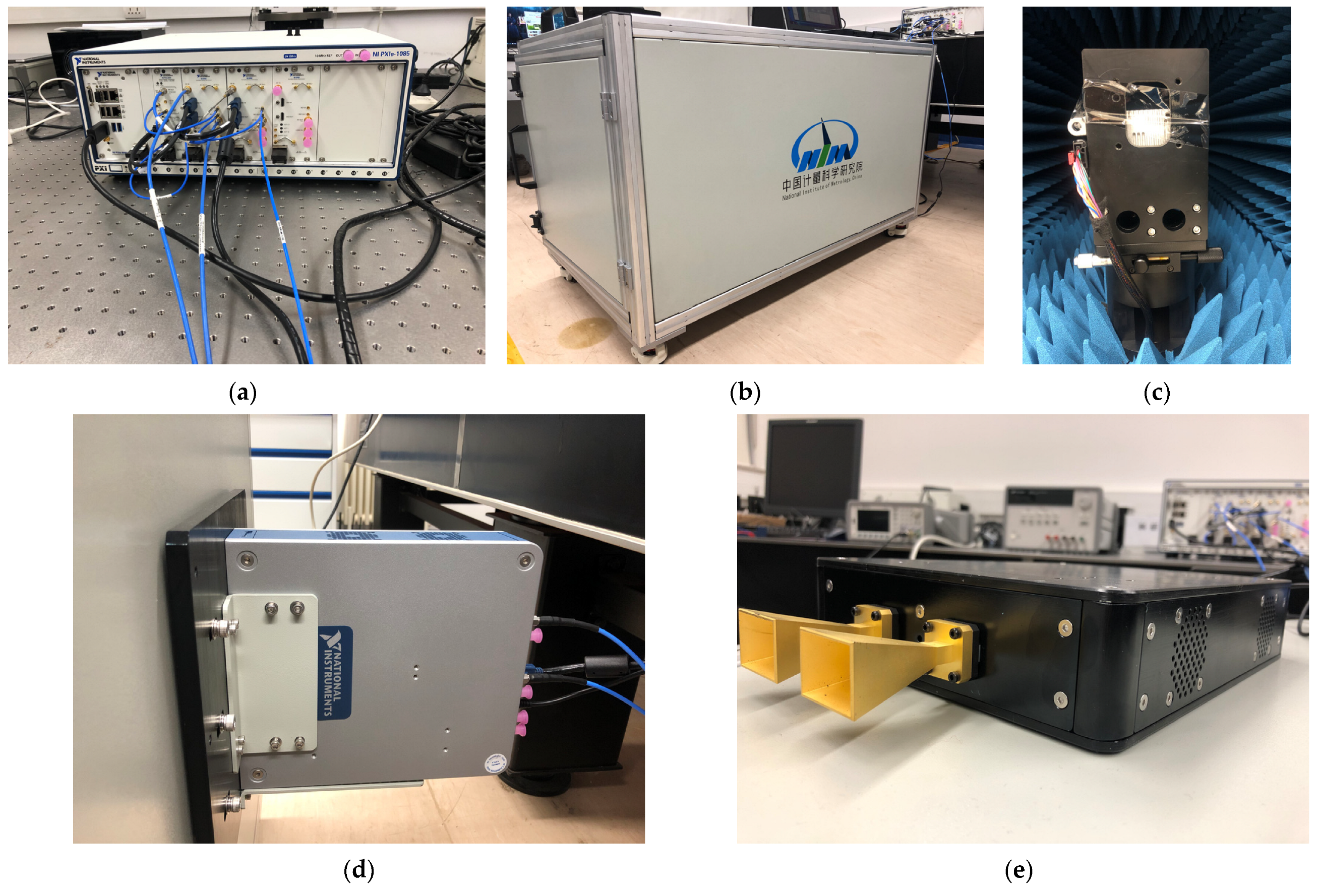
The bi-objective simulation facility includes a hardware part and a software part. As shown in
Figure 6, the hardware part consists of the objective speed and range simulator, turntable, microwave camera obscura, and 77 GHz and 24 GHz millimeter-wave up/down converters.
3.1. Objective Speed and Range Simulator
The objective speed and range simulator (hereinafter referred to as simulator) is shown in
Figure 6a and is established based on the virtual instrument technology of National Instruments (NI). The simulator is composed of a chassis, controller, variable delay generator (VDG), and vector signal transceiver (VST).
The simulator adopts a chassis equipped with 18 slots and 24 GB/s maximum system bandwidth, and which is not only currently able to meet dual-object simulation requirements but can also further improve so as to simulate four objects in the future. Due to the high requirements for operation speed and data throughput of the controller in bi-objective simulation, an NI controller equipped with 24 GB/s bandwidth is selected. During the experimental process, the automotive millimeter-wave radar to be calibrated generates a signal, which is received by the simulator after transmission and conversion by the transceiver antenna and up/down converter. The simulator is programmed by the controller software to set the main parameters of the object. Subsequently, the simulator equipped with two VDGs and a VST board generates dual-object simulated echo signals based on the input parameters of the object and the emitted signal from the radar to be calibrated. By embedding more VDGs and VSTs, the simulator can be updated to realize the simulation of up to four objects.
3.1.1. Speed Calibration Principle
Based on the speed measurement principle of automotive millimeter-wave radar as analyzed in
Section 2, this paper presents a newly developed method for speed calibration. The proposed methodology involves introducing controlled signal modulations on the emitted microwave signals, which is achieved by utilizing a simulator as illustrated in
Figure 6a.
During the calibration, the automotive millimeter-wave radar to be calibrated is fixed on the turntable in the customized microwave camera obscura. The main parameters of the simulated objective vehicle are entered into the simulator, including the simulated initial range
, end range
, initial speed
, end speed
, etc. When
, the simulated objective vehicle is moving away from the radar. Otherwise, the simulated objective vehicle is moving towards the radar. When
, the simulated objective vehicle is accelerating. When
, the simulated objective vehicle is decelerating. When
, the simulated objective vehicle is moving at a uniform speed. Further, the simulator receives the emitted signal of the radar and calculates the simulated Doppler shift
based on Equation (7), which is given by:
where
is the emitted carrier frequency of the radar, and
is the intended simulated speed.
Then, the simulator makes use of the VST to generate a simulated Doppler shift signal
, which is given by:
The simulator receives the emitted signal
expressed as Equation (1), imposes amplitude modulation on the emitted signal
by mixing it with the simulated Doppler shift signal
given in Equation (14), and then generates the simulated echo
, which include two parts of
and
, respectively expressed by:
and
The simulator utilizes the corresponding filters to retain the corresponding part of the simulated echo according to the travel direction of the simulated object. When the approaching direction is set, the part of the simulated echoes in Equation (15) will be retained after filtering, where the frequencies of the simulated echoes will be shifted to . When the departing direction is set, the part of the simulated echoes in Equation (16) will be retained after filtering, where the frequencies of the simulated echoes will be shifted to .
Finally, the simulator re-transmits the two simulated echoes
or
back to the radar to be calibrated. Then, the radar processes the received simulated echoes according to its signal processing algorithm as analyzed in
Section 2 and calculates the simulated speed value
.
3.1.2. Range Calibration Principle
Based on the range measurement principle of automotive millimeter-wave radar as analyzed in
Section 2, this paper presents a newly developed method for range calibration. The proposed methodology involves introducing variable time delays to the emitted microwave signals, which is achieved by utilizing a simulator as illustrated in
Figure 6a.
The intended position
of the simulated object is entered into the simulator, and then the corresponding time delay
can be calculated by the simulator according to Equation (2). The signal emitted by the automotive millimeter-wave radar that is to be calibrated is received by the transceiver antenna and down-converted by the converter shown in
Figure 6d or
Figure 6e, and then the pre-processed signal is sent to the simulator for time delay processing. The simulator makes use of the VDG to conduct time-delay processing on the emitted signal for the time
, and then sends the processed signal to the converter to generate the simulated echo
expressed by:
Finally, the simulator alternately re-transmits the simulated echo
back to the automotive millimeter-wave radar to be calibrated. The radar will process the simulated echo based on its processing algorithm as analyzed in
Section 2, and calculate the simulated range value
:
where
represents the beat frequency obtained by the automotive millimeter-wave radar to be calibrated.
3.2. Transceiver Antenna and Up/Down Converter
In order to meet the requirements of the 24 GHz and 77 GHz millimeter-wave radar simulation test, the facility is equipped with two up/down converters which work at the 24 GHz and 77 GHz frequency bands and are integrated with transceiver antennas as shown in
Figure 6d,e. On one hand, the converters are designed to down-convert the radio frequency (RF) signals from the radar to be calibrated to the intermediate frequency (IF) signals, and so the simulator could easily perform subsequent processing on the IF signals. On the other hand, the processed IF signals by the facility can be up-converted to RF signals through converters and then transmitted into space by antennas. Thus, the radar to be calibrated can receive the processed signals and measure the speed and range of the simulated object based on the measurement principles mentioned in
Section 2. In order to achieve accurate alignment with the radar to be calibrated, a laser sighting device is designed at the front end of the transceiver antenna and the front end of the up/down converter.
3.3. Microwave Camera Obscura
The microwave camera obscura is shown in
Figure 6b. One end of the obscura is equipped with a fixing device to install the up/down converter, and the antenna is placed into the obscura through a small window at this end. The other end of the obscura is designed as an external full-open-door structure for facilitating the installation of radar to be calibrated. Furthermore, the interior walls of the obscura are covered with absorbing materials to reduce the radiant intensity and electromagnetic interference of the external space.
3.4. Turntable
The turntable with a radar sample to be calibrated on it is shown in
Figure 6c. The turntable is installed at one end of the obscura, which is equipped with a fixed support platform to place the radar to be calibrated. The support platform and the turntable are made of non-metallic materials to reduce electromagnetic interference during the calibration. Using the turntable and the support platform we are able to force the radar that is to be calibrated to rotate at the same angle as the turntable, and thus preliminarily realize the angle calibration of the automotive millimeter-wave radar. Furthermore, the transmitting power of the automotive millimeter-wave radar in different directions can be measured with the help of the turntable.
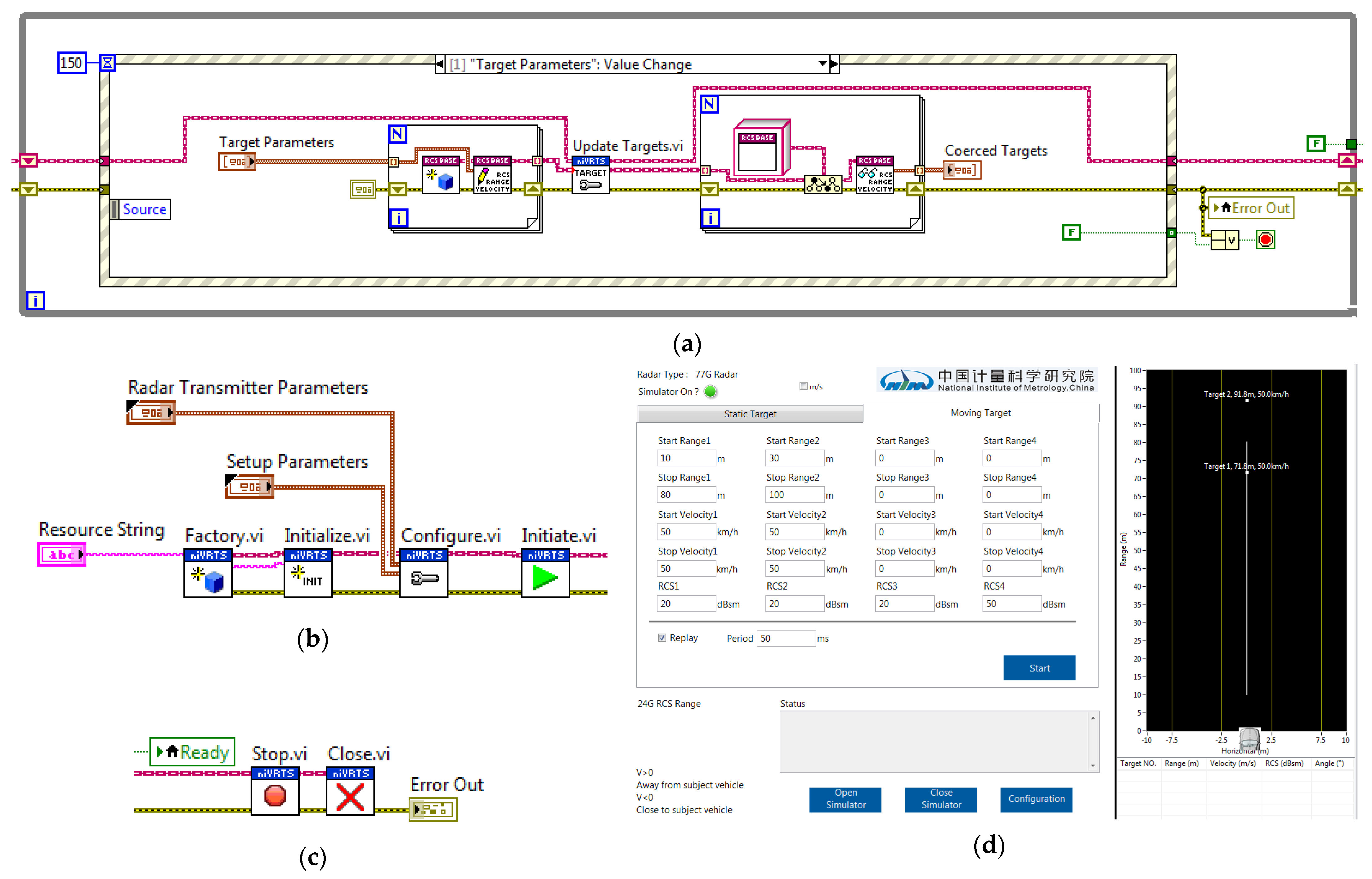
3.5. Control Software
The control software is programmed by LabVIEW and is mainly used for on–off control, parameter setting, and data acquisition of the facility.
Figure 7 shows the overall procedure of the control software. The overall procedure contains three main modules as shown in
Figure 7a–c, including the initial module, object generation module and close module, and
Figure 7d shows the user interface (UI) of the control software with the version number of v1.0.
Firstly, the UI obtains the basic parameters such as the radar type (24 GHz or 77 GHz), sweep bandwidth, center frequency, and effective isotropic radiated power (EIRP). All of these radar’s transmission and setup parameters are sent to the initial module, and the simulator is initiated. Secondly, the object simulation parameters, including position, speed and radar cross section (RCS), are sent to the object generation module to continuously generate the simulated objects. Finally, the simulator is closed by the close module after calibration.
Moreover, the generated objects are displayed on the UI as shown in
Figure 7d. The speed and range calibration parameters of the simulated objects are decided by the entered simulated objective parameters. The measured data of the radar to be calibrated can be transmitted to the computer through WLAN or cable.
4. Calibration and Resolving Ability Test Results
To validate the effectiveness and feasibility of the proposed calibration method and the established simulation facility, two typical automotive millimeter-wave radar samples are chosen to conduct calibration and to resolve ability tests by using the simulation facility in this section. The first sample is a 77 GHz automotive millimeter-wave radar with a center frequency of 76.5 GHz and a sweep bandwidth of 1 GHz, and the second is a 24 GHz automotive millimeter-wave radar with a center frequency of 24.125 GHz and a sweep bandwidth of 200 MHz. According to the resolutions and scopes of the speed and range measurement of the two radar samples, several simulated reference points are selected for the speed and range calibration tests. The speed and range calibration results of the simulated objects are independently measured ten times, and the average of ten independent measurement values is taken as the measured value of the simulated object while calculating the simulated measurement error. The measurement uncertainty of the calibration results is evaluated by referring to the international standard for measurement uncertainty [
27] and China’s national standard for the evaluation and expression of uncertainty in measurement [
28]. Additionally, the speed and range resolving ability test are carried out on the 77 GHz millimeter-wave radar sample to verify that the simulation facility can satisfy the calibration requirements of speed resolution up to 0.01 m/s and range resolution up to 0.1 m for automotive millimeter-wave radars.
4.1. Speed Calibration Results and Measurement Uncertainty Evaluation
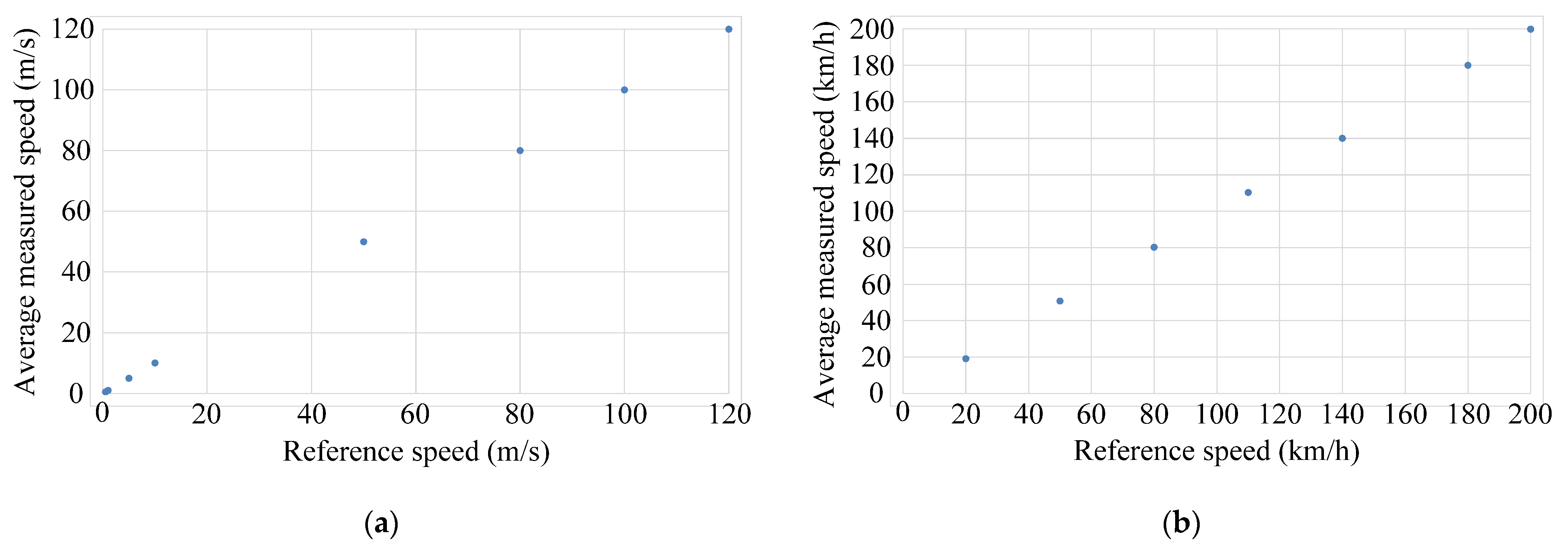
The speed calibration results of the first 77 GHz millimeter-wave radar sample are given in
Table 2 and shown in
Figure 8a. According to the speed measurement scope of the first radar sample, the simulated reference speed points are set to eight typical values within (0.5~120) m/s through the control software.
Table 2 shows that the speed measurement errors for the simulated speed points satisfy the criterion specified within the scope of ±0.03 m/s from 0.5 m/s to 120 m/s, and the standard deviations of ten independent measurements are all within 0.01 m/s. These findings validate the efficacy of the established simulation facility’s speed simulation performance and the proposed automotive millimeter-wave radar speed calibration method.
The speed calibration results of the second 24 GHz millimeter-wave radar sample are given in
Table 3 and shown in
Figure 8b. Seven typical values from 20 km/h to 200 km/h are selected as the simulated reference speed points according to the speed measurement scope of the second radar samples. The speed measurement errors at speeds lower than 110 km/h are out of the scope of ±0.1 km/h, which is worse than that of the first 77 GHz millimeter-wave radar sample, and the standard deviation of ten independent measurements from 20 km/h to 200 km/h are within 0.2 km/h, which is also much worse than that of the first 77 GHz millimeter-wave radar sample.
The measurement uncertainty of the speed calibration results is evaluated as follows. Based on the results given in
Table 2 and
Table 3, the measurement uncertainty components
of the 77 GHz millimeter-wave radar sample and
of the 24 GHz sample, which are obtained by using type A evaluation of standard measurement uncertainty [
27], at the reference speed point
, can be calculated as follows [
27]:
where
and
represent the standard deviations of the 77 GHz and 24 GHz millimeter-wave radar samples given in
Table 2 and
Table 3 respectively.
The measurement uncertainty components
of the 77 GHz millimeter-wave radar sample and
of the 24 GHz sample, which are obtained by using type B evaluation of standard measurement uncertainty [
27], mainly include the speed resolutions of two millimeter-wave radar samples and the maximum permissible error (MPE) of speed simulation of the bi-objective simulation facility given in
Table 1. Estimating with the rectangular distribution,
and
can be calculated as follows [
27]:
where the MPE of speed simulation is
as shown in
Table 1 and the speed resolution of the 77 GHz millimeter-wave radar sample is 0.01 m/s while that of the 24 GHz millimeter-wave radar sample is 0.1 km/h.
According to the measurement uncertainty components obtained by using type A and type B evaluation of standard measurement uncertainty, the expanded uncertainties
and
(
k = 2) of the 77 GHz and 24 GHz millimeter-wave radar samples can be calculated by [
27]:
The measurement uncertainty components and expanded measurement uncertainty of the 77 GHz and 24 GHz radars at
are summarized in
Table 4. The above speed calibration results and measurement uncertainty evaluation results given from
Table 2,
Table 3 and
Table 4 indicate that the speed measurement performances of the 77 GHz millimeter-wave radar sample are better than those of the 24 GHz millimeter-wave radar sample in terms of error, scope, and uncertainty of speed measurement.
4.2. Speed Resolving Ability Test of the 77 GHz Millimeter-Wave Radar
The speed measurement performance of the 77 GHz millimeter-wave radar is superior to the 24 GHz performance due to its higher working frequency. The speed measurement resolution of the 77 GHz millimeter-wave radar sample is 0.01 m/s according to its technical manual. To evaluate its speed measurement resolution, several reference values from 0.3 m/s to 0.5 m/s are selected for the speed resolving ability test, and the testing results are shown in
Table 5.
According to the nominal speed resolution of the 77 GHz millimeter-wave radar sample, the reference speed values increase from 0.30 m/s to 0.31 m/s, from 0.40 m/s to 0.41 m/s and from 0.50 m/s to 0.51 m/s. The experimental result indicates that the 77 GHz millimeter-wave radar sample can accurately distinguish all the reference speed variations consistent with its speed resolution, which can validate the nominal speed measurement resolution of the 77 GHz millimeter-wave radar sample and the speed simulation performance of the established simulation facility. Therefore, the simulation facility can satisfy the calibration requirements of speed resolution up to 0.01 m/s for automotive millimeter-wave radars.
4.3. Range Calibration Results and Measurement Uncertainty Evaluation
The range calibration results of the first 77 GHz millimeter-wave radar sample are given in
Table 6. According to the range measurement scope of the first 77 GHz millimeter-wave radar sample, the simulated reference range points are set to four typical values within (50~210) m through the control software.
Table 6 shows that the range measurement errors of the 77 GHz radar sample are within the scope of ±0.15 m from 50 m to 150 m and out of the scope of ±1.0 m from 160 m to 210 m. However, the standard deviations of 10 independent measurements are out of 0.04 m from 50 m to 150 m and within 0.01 m from 160 m to 210 m.
The range calibration results of the second 24 GHz millimeter-wave radar sample are given in
Table 7. Four typical values from 30 m to 90 m are selected as the simulated reference range points according to the range measurement scope of the second 24 GHz radar sample. The range measurement error is up to 3.366 m at 90 m, which is much worse than that of the first 77 GHz radar sample. However, the standard deviations of 10 independent measurements are all within 0.01 m from 30 m to 90 m, which is better than that of the first 77 GHz millimeter-wave radar sample.
The measurement uncertainty of the range calibration results is evaluated as follows. Based on the results given in
Table 6 and
Table 7, the measurement uncertainty components
of the 77 GHz millimeter-wave radar sample and
of the 24 GHz sample, which are obtained by using type A evaluation of standard measurement uncertainty [
27], at the reference range point
can be calculated as follows [
27]:
where
and
represent the standard deviation of the 77 GHz and 24 GHz millimeter-wave radar samples, respectively.
The measurement uncertainty components
of the 77 GHz millimeter-wave radar sample and
of the 24 GHz sample, which are obtained by using type B evaluation of standard measurement uncertainty [
27], are the range resolution of two millimeter-wave radar samples and the MPE of range simulation of the bi-objective simulation facility given in
Table 1. Estimating with the rectangular distribution,
and
can be calculated as follows [
27]:
where the MPE of the range simulation is
as shown in
Table 1 and the nominal range resolutions of the 77 GHz and 24 GHz millimeter-wave radar samples are both 0.01 m.
According to the measurement uncertainty components obtained by using type A and type B evaluation of standard measurement uncertainty, the expanded uncertainties
and
(
k = 2) of the 77 GHz and 24 GHz millimeter-wave radars can be calculated by [
27]:
According to the range calibration results and measurement uncertainty evaluation analyses of the two millimeter-wave radar samples, the range measurement error of the 77 GHz millimeter-wave radar sample is smaller than that of the 24 GHz one as shown in
Table 6 and
Table 7. Considering the range measurement principle of automotive millimeter-wave radar, the range measurement accuracy of the 77 GHz millimeter-wave radar should be better than that of the 24 GHz millimeter-wave radar because the working frequency bandwidth of 77 GHz millimeter radar is wider than that of the 24 GHz radar. However, the range measurement uncertainties of two millimeter-wave radar samples are equivalent at
m according to the evaluation results shown in
Table 8, which means the 77 GHz radar sample has no significant advantage in range measurement uncertainty compared with the 24 GHz one.
4.4. Range Resolving Ability Test of the 77 GHz Millimeter-Wave Radar
The range measurement error of the 77 GHz millimeter-wave radar sample is smaller than that of the 24 GHz millimeter-wave radar sample as aforementioned. Therefore, the 77 GHz millimeter-wave radar sample is selected to evaluate its range measurement resolution.
As the nominal range resolution of the 77 GHz millimeter-wave radar sample is 0.01 m according to its technical manual, the reference range values firstly increase from 20 m to 20.01 m, from 30 m to 30.01 m, and from 40 m to 40.01 m, respectively. However, the range measurement values have no variations with the step interval of 0.01 m at all the reference range points. The step interval is then changed to 0.1 m, and the reference range values increase from 20 m to 20.1 m, from 30 m to 30.1 m, and from 40 m to 40.1 m, respectively. The testing results are shown in
Table 9. The 77 GHz millimeter-wave radar sample can distinguish all the reference range variations with the step interval of 0.1 m. The measurement errors of the range resolving ability are all within
at the reference range points as shown in
Table 9. Based on the rounding-off method, the simulation facility can satisfy the calibration requirements of range resolution up to 0.1 m for automotive millimeter-wave radars.
4.5. Discussion
The calibration results of the speed and range measurement performances of the 77 GHz and 24 GHz millimeter-wave radar samples indicate the existence of potential measurement uncertainty sources that can affect the speed and range performance of the radar sample being calibrated.
In terms of the speed measurement performance, the 77 GHz millimeter-wave radar has a speed measurement scope of 0.5~120 m/s (1.8~432 km/h) with a resolution of 0.01 m/s, while the 24 GHz millimeter-wave radar has a speed measurement scope of 5.6~55.6 m/s (20~200 km/h) with a resolution of 0.1 km/h (approximately equal to 0.03 m/s). As the 77 GHz millimeter-wave radar has a higher working frequency than the 24 GHz millimeter-wave radar, the speed resolution of the former is higher than that of the latter. At the reference speed point m/s (180 km/h), the measurement uncertainty components caused by measurement repeatability of the 77 GHz and 24 GHz millimeter-wave radar samples are 0.00167 m/s (0.006012 km/h) and 0.065 km/h, respectively. Therefore, the speed measurement performances of the 77 GHz millimeter-wave radar sample are superior to those of the 24 GHz millimeter-wave radar sample, including speed measurement resolution and accuracy.
The range measurement performance of millimeter-wave radar is closely related to the working frequency and bandwidth. Theoretically, the range measurement performance of a 77 GHz millimeter-wave radar should be better than that of a 24 GHz millimeter-wave radar, because the working bandwidth of the former is wider than that of the latter. In terms of the range measurement error of the range calibration results that are given in
Table 6 and
Table 7, the range measurement errors of the 77 GHz millimeter-wave radar sample are much smaller than those of the 24 GHz millimeter-wave radar sample at the reference range point.
Because the speed and range measurement performances of a 77 GHz millimeter-wave radar are superior to those of a 24 GHz millimeter-wave radar, the 77 GHz millimeter-wave radar sample is selected for the speed and range resolving ability test, and the test results verify that the simulation facility can satisfy the calibration requirements of speed resolution up to 0.01 m/s and range resolution up to 0.1 m for automotive millimeter-wave radars.
The above speed calibration results and measurement uncertainty evaluation results have verified that the speed measurement performances of the 77 GHz millimeter-wave radar sample are better than those of the 24 GHz millimeter-wave radar sample in terms of error, scope, and measurement uncertainty. The range calibration results have verified that the range measurement error of the 77 GHz millimeter-wave radar sample is smaller than that of the 24 GHz one. However, the 77 GHz radar sample has no significant advantage in range measurement uncertainty compared with the 24 GHz radar sample according to the range measurement uncertainty evaluation results. Additionally, the speed and range resolving tests indicate that the simulation facility can meet the speed and range calibration requirements of 77 GHz and 24 GHz radars with high resolution.
5. Conclusions and Future Work
As for environmental perception sensors of automated vehicles, 24 GHz and 77 GHz millimeter-wave radars play an indispensable role in the automotive field. It is worth paying attention to the conducting of effective, accurate and traceable kinematic parameter calibrations of automotive millimeter-wave radar. In this paper, a speed and range calibration method for automotive FMCW millimeter-wave radars is proposed and a bi-objective simulation facility for speed and range calibration of 24 GHz and 77 GHz automotive millimeter-wave radars is established. The speed calibration scope of the simulation facility is up to (−500~500) km/h and the MPE of the simulated speed is ±0.1 km/h. The range calibration scope is up to (5~300) m and the MPE of the simulated range is ±0.1 m. Then, we conducted speed and range calibration testing on two typical automotive millimeter-wave radars for environmental perception working at 24 GHz and 77 GHz, respectively. The calibration results indicate that the speed and range measurement performances of the 77 GHz millimeter-wave radar sample are superior to the 24 GHz performances, but that the 77 GHz millimeter-wave radar sample has no significant advantage on range measurement uncertainty. Additionally, we performed speed and range resolving tests on the 77 GHz millimeter-wave radar sample. The calibration results and measurement uncertainty evaluation results of two typical millimeter-wave radar samples validated the feasibility of the proposed calibration method and the simulation performance of the established simulation facility, which can effectively meet the speed and range calibration requirements of 24 GHz and 77 GHz automotive millimeter-wave radars.
For future work, we will conduct further study on the calibration method for millimeter-wave radar in the field and establish a portable calibration facility for millimeter-wave radar in actual traffic. Additionally, the study of angle calibration will be carried out in the future.


