Article

Adaptive Droop Control of VSC-MTDC System Based on Virtual Inertia

College of Electrical and Information Engineering, Zhengzhou University of Light Industry, Zhengzhou 450002, China
*
Author to whom correspondence should be addressed.
Electronics 2023, 12(10), 2324; https://doi.org/10.3390/electronics12102324
Submission received: 14 April 2023 / Revised: 15 May 2023 / Accepted: 18 May 2023 / Published: 21 May 2023

Abstract

:
In order to solve the problem that the voltage source converter based multi-terminal direct current (VSC-MTDC) system cannot provide inertia and participate in frequency modulation after connecting to the AC power grid under the traditional control strategy, an adaptive control strategy based on virtual inertia is proposed. First, the relationship between AC frequency and DC voltage was established by a virtual inertia control, allowing the VSC-MTDC system to provide inertia to the AC side. Second, to address the limited inertia coefficient selection due to DC voltage deviation, an adaptive control was adopted. When the DC voltage deviation is small, the inertia coefficient is increased to obtain a better inertial response; on the contrary, the inertia coefficient is reduced to prevent the DC voltage from exceeding the limit. Finally, to solve the problem of insufficient flexibility of the fixed droop coefficient, this paper introduces the power margin of a VSC-station into the droop coefficient to dynamically adjust the distribution ratio of unbalanced power and reduce the DC voltage deviation. The three-terminal VSC-MTDC system was modelled on the PSCAD/EMTDC simulation platform, and the superiority of the control strategy was highlighted in this paper by comparing it with conventional droop control and a fixed virtual inertia coefficient.

1. Introduction

Due to the intermittent and randomness of new energy generation, the traditional AC grid is greatly challenged in the connection and transmission of new energy. Compared with traditional AC transmission, the voltage-source-converter-based multi-terminal direct current (VSC-MTDC) system can supply power to passive networks without phase change failure problems, which has gradually become the best choice for new energy grid connections [1,2,3].
The control objective of the VSC-MTDC system is the maintenance of DC voltage stability and power balance. At present, the main control methods include master-slave control, voltage margin control and droop control. In the primary–secondary control, the main VSC station regulates the DC voltage, and the remaining VSC stations regulate the active power or current. The primary–secondary control is simple to implement, but its stability is poor. If the main VSC station is not operating owing to a fault, it will lose control of the DC voltage which decreases rapidly [4]. The voltage margin control sets different reference voltages for different VSC stations; if the main VSC station is not operating owing to a fault, the remaining VSC stations can be switched to constant DC voltage operation to maintain the system stability. However, the limited voltage margin limits the number of VSC stations which can be connected to the MTDC system. The droop control uses the power regulation capability of multiple VSC stations to achieve rapid distribution of unbalanced power [5,6]. However, the stable operation of the system may be affected by the DC voltage deviation caused by the droop control.
With the gradual increase in the proportion of power electronics, the overall inertia of the system decreases, resulting in larger frequency fluctuations in the system when there is a disturbance. At the same time, when the AC system is interconnected via the VSC-MTDC system, the DC power is insensitive to the grid frequency at the sending and receiving ends, and cannot provide inertia for the AC side like a synchronous generator, further weakening the frequency regulation capability [7]. Many scholars have conducted relevant studies to address the above issues.
Reference [8] added a frequency signal to the VSC station droop control, which allows the DC system to respond to AC frequency changes without communication. However, the droop coefficient is a constant value, which makes it difficult to accurately distribute the DC-side power. Reference [9] introduced frequency deviation and a VSC power margin into the droop coefficient based on reference [8], and dynamically adjusted the droop coefficient to achieve a reasonable allocation of unbalanced power and avoid large frequency offsets in weak AC systems. In [10], a nonlinear droop control strategy considering DC voltage and frequency was proposed to achieve DC voltage stabilization and frequency regulation. However, the coordinated action of multiple converters was not considered. References [11,12] analyzed the supporting effect of inertia on frequency, and proposed a concept of virtual inertia for distributed power systems. This method simulates the inertia of a synchronous generator by using the energy of DC capacitance to provide frequency support. However, this control strategy was only applied in two-terminal flexible DC transmission and was not tested in multi-terminal flexible systems. In [13], a virtual inertia control was applied to the VSC-MTDC system and the effect of selecting the virtual inertia coefficient on the DC voltage was considered. However, the virtual inertia coefficient is a constant value, which limits the ability of the DC system to participate in frequency regulation. References [14,15] proposed a DC system based on a virtual synchronous generator to participate in an AC frequency modulation control strategy, but its inertia was fixed, and there was still some room for improvement. References [16,17] adapted the adaptive inertia control strategy and successfully applied it to the microgrid, which can enhance the system stability, but the application in VSC-MTDC systems needs further research.
This paper proposes an adaptive droop control strategy for a VSC-MTDC system based on virtual inertia, which utilizes DC capacitor energy to provide inertia for the AC side while maintaining droop control on the DC side. Since the virtual inertia coefficient is affected by the DC voltage deviation, the method of adaptively adjusting the inertia coefficient according to the DC voltage deviation was used. When the DC voltage deviation is small, the inertia coefficient is increased to achieve a better frequency regulation effect; when the DC voltage deviation is large, the inertia coefficient is decreased to prevent the DC voltage from exceeding the limit. Then, the droop coefficient is adaptively adjusted in accordance with the power margin of the VSC station in order to reasonably distribute the DC side power. Finally, a simulation was performed to verify the effectiveness of the proposed control strategy.

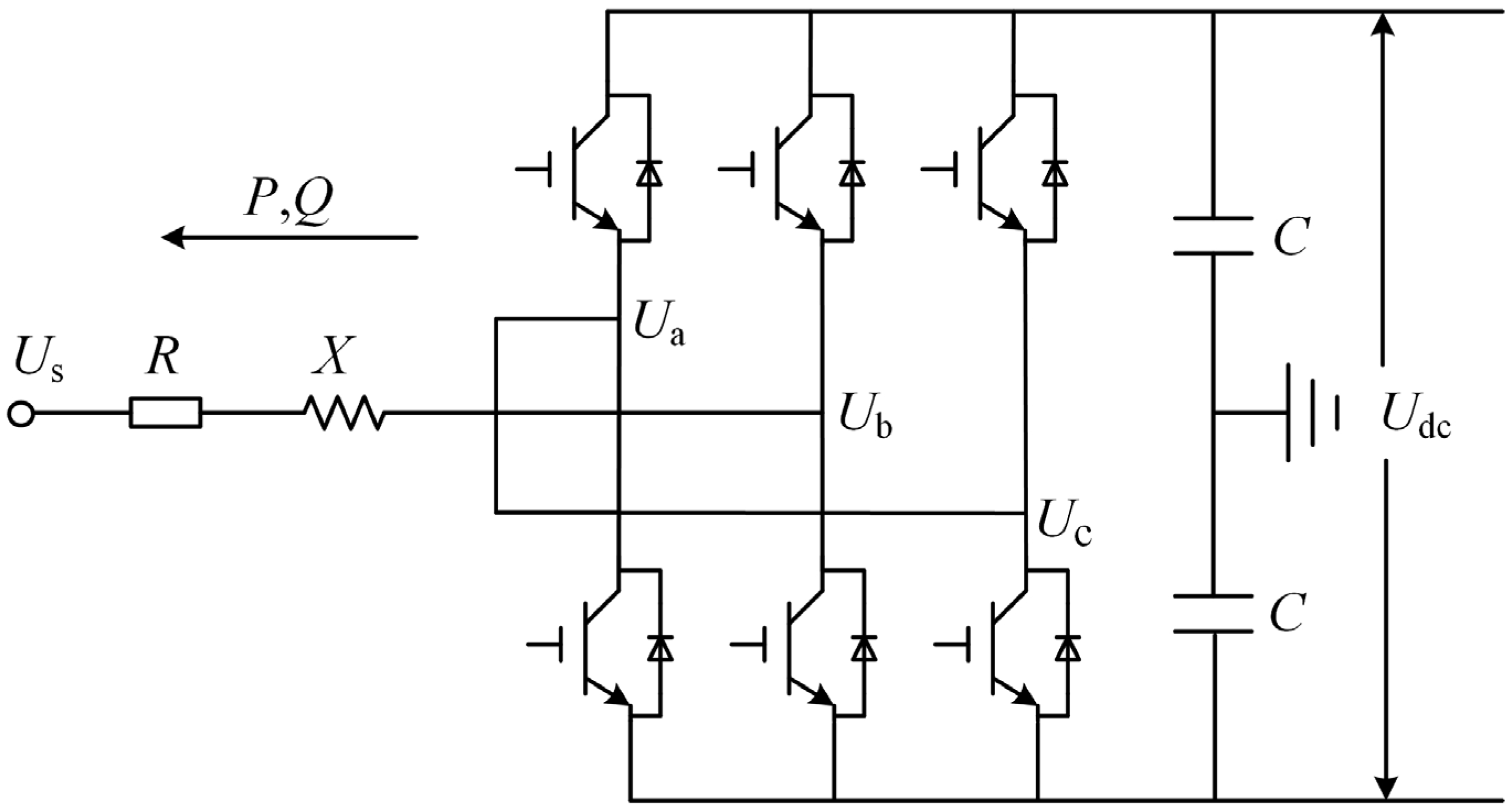
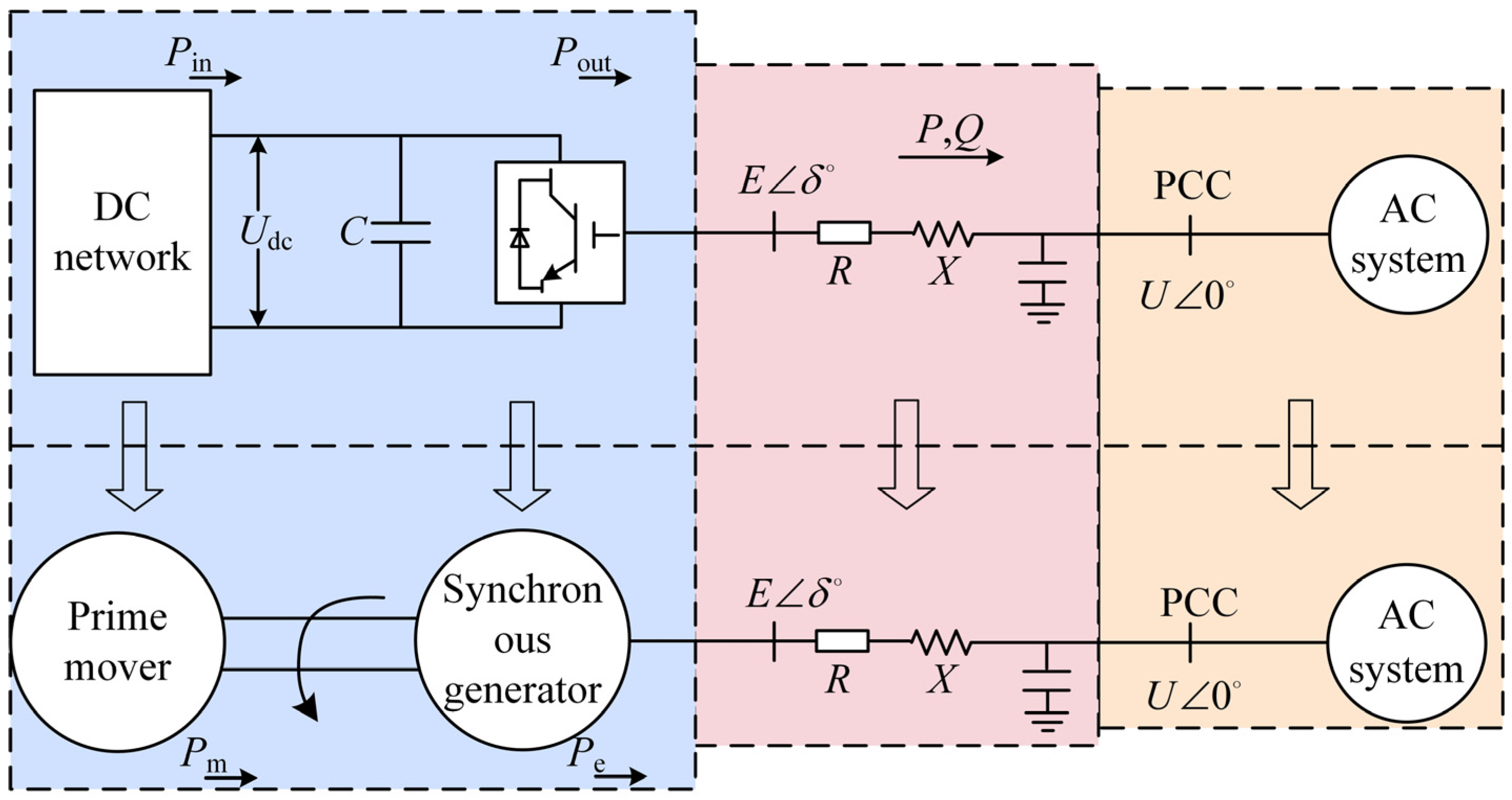
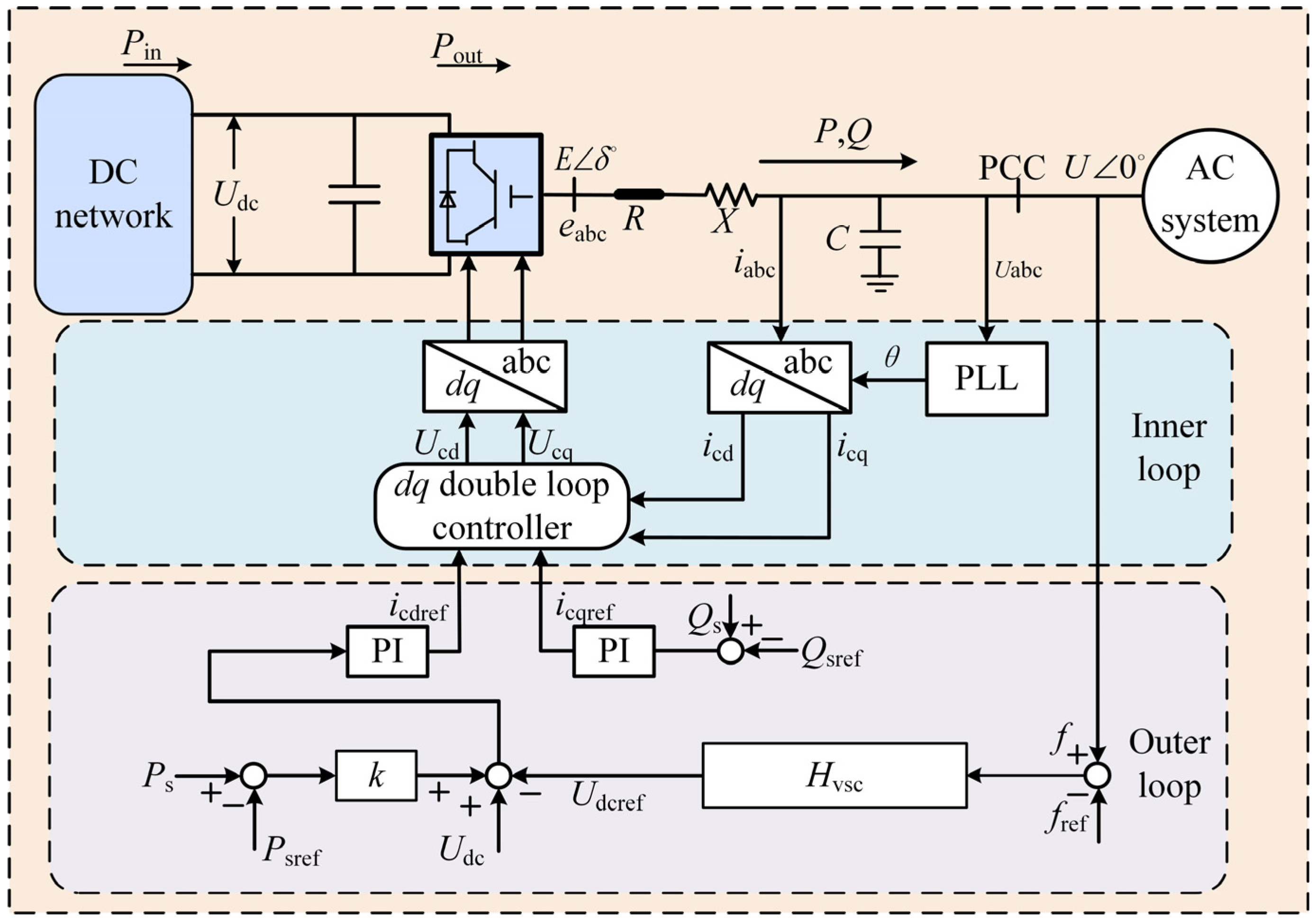
2. VSC-MTDC System Structure and Mathematical Model

Multi-terminal DC transmission technology is based on two-terminal DC transmission and typically consists of three or more VSC stations. If one VSC station is decommissioned, power can still be transferred between the remaining VSC stations and can be used to interconnect AC networks and transport power. A three-terminal VSC-MTDC system architecture is shown in Figure 1, where the DC side of VSC1–VSC3 is connected in parallel through the DC network. AC1–AC3 is the active AC system, and P + jQ is the AC side load.
For the three-terminal VSC-MTDC system shown in Figure 1, it is assumed that there is a load disturbance at any end of the AC system. Because there is no communication between the VSC stations, the VSC station operating in the constant active power mode cannot change its output power, and the DC voltage will not change since the other AC systems cannot provide emergency power support. The fault-side system can only rely on the power frequency characteristics of the generator itself and the power characteristics of the load to achieve active balance, and the frequency usually has a large deviation.
From the above analysis, it can be seen that there are certain advantages in the VSC station isolating AC side faults. At the same time, due to the insensitivity of the DC system to the frequency of the AC system, it is impossible to support each other through the VSC-MTDC system, which sacrifices the ability of each AC system to support each other. If each AC system can provide mutual power support, the frequency deviation of the fault side system can be effectively reduced. Although the frequency deviation of the normal side AC system will exist, it is within the acceptable range.
The structure of the VSC is shown in Figure 2. Us is the AC side voltage; Ua, Ub and Uc are the three-phase voltages on the AC side of the VSC, respectively; R and X are the equivalent resistance and reactance on the AC side of the VSC, respectively; C is the DC side capacitor; and Udc is the DC side voltage.
The mathematical model of a VSC in a two-phase rotating dq coordinate system is
{ L d i sd d t + R i sd = u sd u d + ω L i sq L d i sq d t + R i sq = u sq u q ω L i sd ,
where usd is the d-axis component of the AC-side grid voltage; usq is the q-axis component of the AC-side grid voltage; ud is the d-axis component of the AC-side voltage; uq is the q-axis component of the AC-side voltage; isd is the d-axis component of the AC-side grid current; isq is the q-axis component of the AC-side grid current; and ω is the synchronous rotational angular velocity of the grid voltage vector.

3. Adaptive Droop Control Strategy Based on Virtual Inertia

3.1. Control of the Virtual Inertial Frequency

The energy stored in the generator rotor, Eg, is
E g = 1 2 J ω 0 2 ,
where J is the rotational inertia and ω0 is the rated rotor speed.
The DC capacitive energy Ec is
E c = 1 2 C 0 U 2 ,
where C0 is the capacitance value and U is the capacitance voltage [18].
In contrast to Equations (2) and (3), the VSC station and the synchronous generator have similar power balance characteristics; this allows the VSC station to simulate the operating characteristics of the synchronous generator to provide inertia for the AC side, as shown in Figure 3.
In Figure 3, the reactance X is equivalent to the armature reactance of the synchronous generator; R is equivalent to the armature resistance; the mechanical power output by the prime mover is Pm; and the electromagnetic power of the synchronous generator is Pe.
The inertia of a conventional power system is supplied by the energy stored by the rotor of the synchronous generator, and the equation of motion of the rotor can be written as
2 H f ref d f d t = P m P e = Δ P 1 ,
where f and fref are the measured and rated frequency values, respectively, and H is the inertia time constant of the synchronous generator.
The balance equation of the DC capacitor voltage at the VSC station is
N m C U dc S vsc d U dc d t = P in P out = Δ P 2 ,
where Nm is the number of DC capacitors; Svsc is the rated capacity of the VSC station; and Pin and Pout are the input and output power of the VSC station, respectively.
According to Equation (4), if the input and output power are not equal, the generator speed will change and the rotational kinetic energy of the rotor will compensate for the power difference. According to Equation (5), when the DC system power is unbalanced, the DC capacitor will perform charging and discharging actions and the DC voltage will start to change until the system reaches a new balanced state [19].
Combining Equations (4) and (5), we can obtain
2 H vsc f ref d f d t = N m C U dc S vsc d U dc d t ,
where Hvsc is the virtual inertia constant. Hvsc has the same meaning as the inertia time constant of the generator, except that it is generated virtually by the flexible DC system. The Hvsc value reflects the magnitude of the virtual inertia generated by the converter and its ability to suppress frequency variations.
Integrating both ends of Equation (6) and substituting fref and the DC voltage rating Udcref, we can obtain
U dc = U 2 dcref + 4 H vsc S vsc N m C f ref ( f f ref ) ,
Because the AC frequency usually does not vary much, Equation (8) is obtained by expanding it with Taylor’s formula, ignoring the higher-order terms above the second order.
U dc = U dcref + 2 H vsc S vsc N m C f ref U dcref ( f f ref ) ,
From Equation (8), it can be seen that, similar to the frequency deviation multiplied by coefficient feedback control strategy, this control strategy provides inertia for the AC side.
The value of HVSC measures the ability of the converter to provide inertia: the higher the value, the greater the stabilization effect on the frequency and vice versa. When HVSC is fixed, it is important to ensure that the DC voltage of the system does not exceed the limit during normal operation. Meanwhile, to control the DC voltage deviation, a low HVSC should be maintained when Udc is close to Udcmax or Udcmin. Conversely, a high HVSC should be maintained when the DC voltage is far from the limit; at the same time, as Udc approaches the limit value of Udcref, the HVSC value should be gradually reduced to 0.
Frequency deviation and DC voltage deviation are defined as
{ Δ f = f f ref Δ U dc = U dc U dcref ,
In general, Δf is generally within ±0.5 Hz, while ΔUdc is usually within 5% of the rated voltage. Substituting the above parameters into Equation (8), we get
U dc ± Δ U dcmax = U dcref + 2 H vsc S vsc N m C f ref U dcref ( ± 0.5 ) ,
where ΔUdcmax is the maximum deviation of the DC voltage.
Solving Equation (10) yields the Hvsc expression
H vsc = { Δ U dcmax + Δ U dc S vsc N m C f ref U dcref   ( f min < f < f ref ) Δ U dcmax Δ U dc S vsc N m C f ref U dcref   ( f ref < f < f max ) ,
According to Equation (11), when f gradually increases from fmin to fref, |ΔUdc| gradually decreases and Hvsc gradually increases, ensuring that the system has a large frequency modulation capability. When f gradually increases from fref to fmax, |ΔUdc| gradually increases and Hvsc gradually decreases, preventing the DC voltage from exceeding the limit.

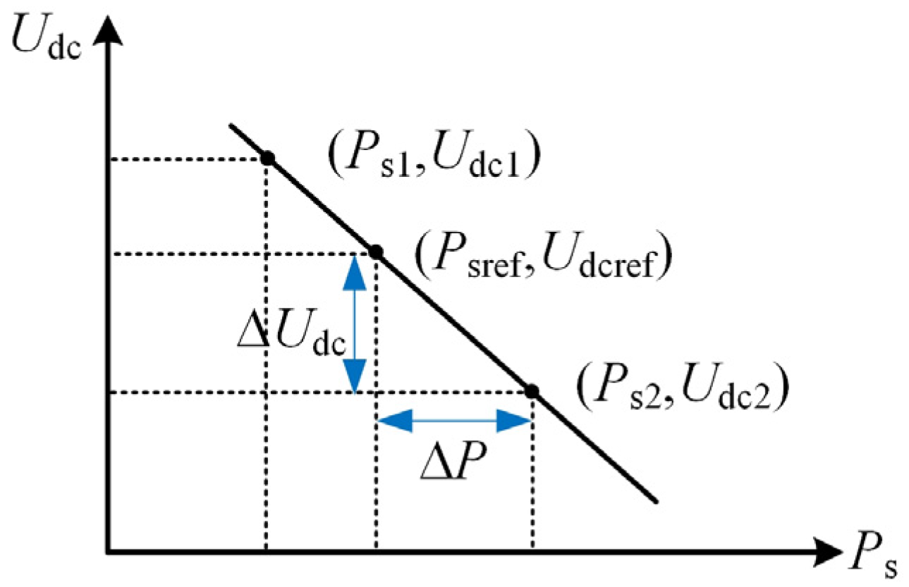
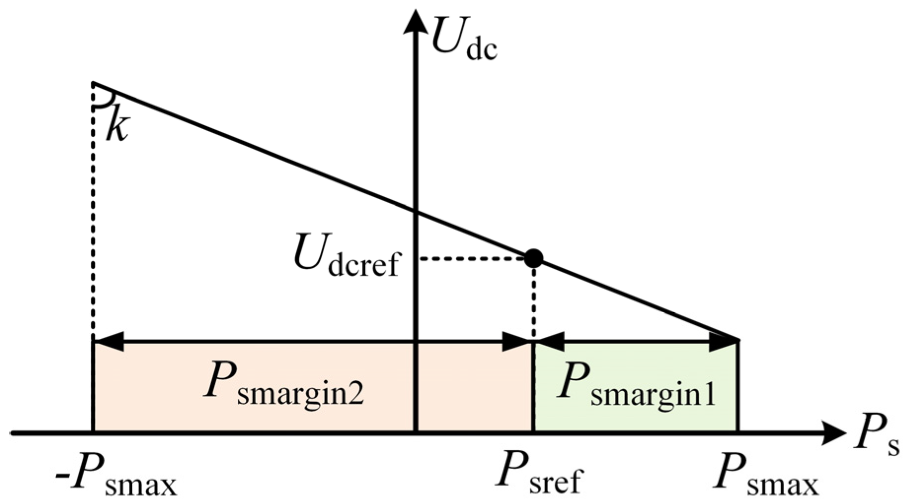
3.2. Analysis of Conventional DC Voltage Droop Control Characteristics

Analogous to the primary frequency control characteristics of conventional generators, droop control does not require inter-station communication and uses the DC voltage and active power characteristics to achieve fast unbalanced power distribution and stable DC voltage control. Figure 4 and Figure 5 show the structure and operating characteristics of the droop control.
From Figure 4, we can obtain
e ( t ) = U dc U dcref + k ( P s P sref ) ,
where e(t) is the PI input; k is the droop coefficient; and Ps and Psref are the measured and reference values, respectively [20,21].
When the system is stable, the PI controller input is 0 and Equation (12) can be reduced to
U dc = U dcref + k ( P s P sref ) ,
Assuming a VSC-MTDC system with N VSC stations using droop control, when an unbalanced power ΔP occurs in the DC network, each droop station automatically finds a new balance point through the droop curve. When the system returns to stability, the relationship between the ΔPi borne by VSC station i (0 < I < N) and ΔUdc is
Δ P i = Δ U dc k i ,
where ki is the droop coefficient of the ith VSC station.
For the whole DC system, the sum of the unbalanced power borne by the N droop stations should be equal to the ΔP.
Δ P = i = 1 N Δ P i = Δ U dc i = 1 N 1 k i ,
Combining Equations (14) and (15), we get
Δ P i = Δ P k i i = 1 N 1 k i ,
According to Equation (16), the ΔPi is inversely proportional to ki: the smaller the droop coefficient, the greater the unbalanced power carried by the VSC station. In general, the larger the capacity of the VSC station, the more unbalanced power it will take on, thus ensuring stable system operation [22,23].
The system control block diagram is shown in Figure 6.
In Figure 6, the outer-loop and inner-loop control are the main components of the overall system control. The outer loop mainly controls the active power and DC voltage of the AC system, tracking the controlled variable to the reference value, while using the output signal as the reference signal for the inner-loop current control. The inner-loop controller tracks the current setpoint of the outer-loop output by the PI control to achieve non-differential current control, and converts the current signal to a voltage signal to generate PWM pulses to control the shutdown of the devices in the VSC, thus achieving system tidal voltage control. From the outer-loop control, the principle of virtual inertia control is that inertia is created only by varying the DC voltage, which is acted upon by the control system to produce a change in DC voltage. The inertial power consists of two parts: one part is the energy storage of the DC capacitor of the VSC station and the other part is the power support of the other VSC stations of the DC system; this is analyzed in detail below.
When a VSC station uses virtual inertia control, it is assumed that as the load on the AC system increases, the DC voltage will decrease and the DC capacitor will discharge, releasing energy to provide inertia on the AC side. At the same time, due to the change in DC voltage, power from the other droop stations in the DC system will flow to this VSC station, allowing the capacitor energy to be replenished. The following section provides a detailed analysis of the values of the droop coefficient.

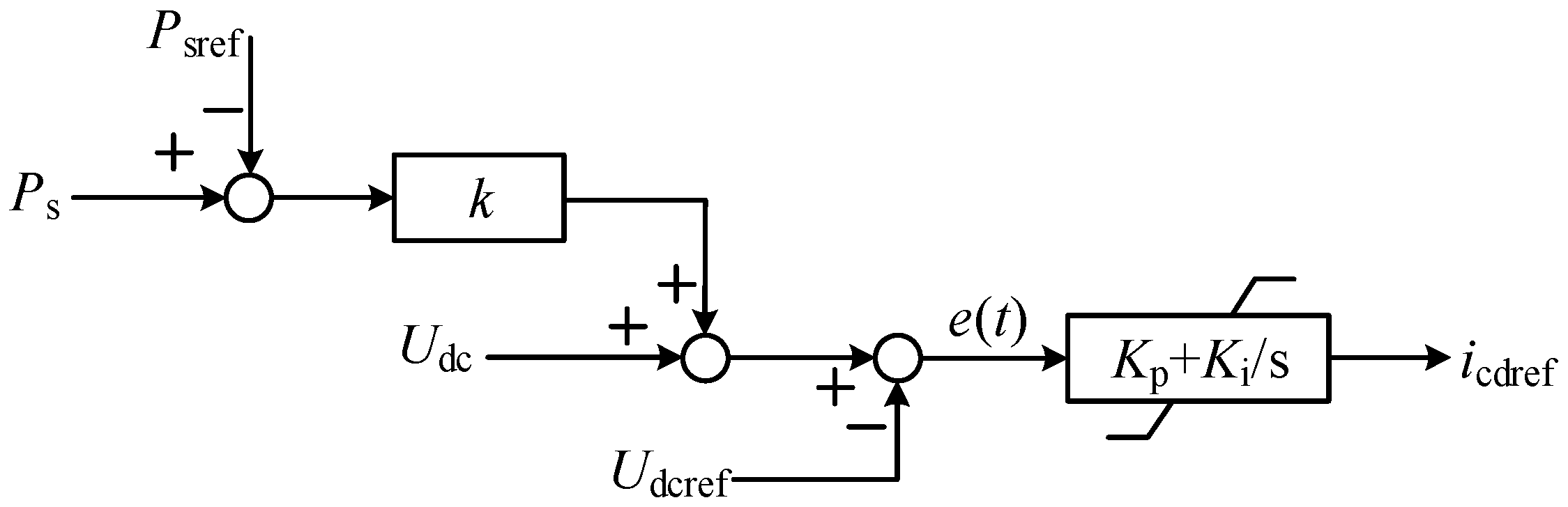
3.3. Adaptive Droop Control Strategy Considering Power Margin

As can be seen from Equation (16), the use of fixed droop coefficients for the VSC stations has the disadvantage of not taking into account the power margin under actual operating conditions. When the system normally dissipates unbalanced power, there will be a situation where some of the VSC stations still have a power margin, while others lose the ability to respond to changes in the DC system due to the full load switching to fixed power operation.
Using Psmax and −Psmax to denote the maximum power allowed in the forward direction and the maximum power in the reverse direction of the VSC station, respectively, the operating interval of the VSC station can be represented in Figure 7.
In Figure 7, Psmargin1 is the forward power margin and Psmargin2 is the reverse power margin. The power margin R of the VSC station is
R = { P smargin 1 = P smax P s   ( U dcmin U dc U dcref ) P smargin 2 = P smax + P s   ( U dcref < U dc U dcmax ) ,
As shown in Figure 7, when Ps is greater than 0 and moves to the right, Psmargin1 is gradually decreasing, while Psmargin2 is gradually increasing. In other words, there is a power margin when the VSC station moves toward the maximum power point [24,25]. Therefore, the power margin Psmargin1 needs to be considered when dynamically correcting the droop coefficient. Instead, the focus is on the power margin Psmargin2. Therefore, in order to make better use of the power support capability of each AC system, the power output of the converter station with a larger power margin can be increased, the power output of the converter station with a smaller power margin can be reduced, and the DC voltage deviation can be further reduced.
Based on the above analysis, this paper introduces the power margin of the VSC station into the droop coefficient, and reasonably distributes the unbalanced power by dynamically adjusting the droop coefficient. First, the initial droop coefficient k is determined in inverse proportion to the rated capacity of the VSC station, and then the value of k is corrected dynamically according to the available power margin of each VSC station [26,27]. At the same time, the droop coefficient should remain unchanged when the system is not disturbed. The expression for the adaptive droop coefficient is
k i = { ( 0.5 + P s max + P s 2 P s max ) α × k P s > 0   ( 0.5 + P s max P s 2 P s max ) α × k P s 0   ,
where the index α is a constant used to adjust the droop coefficient variation to the VSC station’s available power margin. Considering the different values of the initial active power command of the VSC station, too large of a value for α is likely to lead to an excessive correction of the droop coefficient, weakening the ability of the VSC station to adjust unbalanced power; too small of a value for α will easily lead to a full load regulation problem in the VSC station. Substitute the relevant data into Equation (18), and the relationship between ki and Ps and α is shown in Figure 8.

4. Simulation and Analysis

To verify the effectiveness of the proposed control strategy, a simulation model of a three-terminal flexible DC transmission system based on PSCAD/EMTDC was established as shown in Figure 1, and the simulation parameters are shown in Table 1. Three conditions were selected for simulation comparison: AC grid load increase, AC grid load decrease, and single-phase short circuit fault in the AC grid. The control methods used in the comparison experiments are as follows:
Control strategy 1 (CM1): conventional droop control;
Control strategy 2 (CM2): fixed inertia and adaptive droop control;
Control strategy 3 (CM3): adaptive inertia and adaptive droop control.

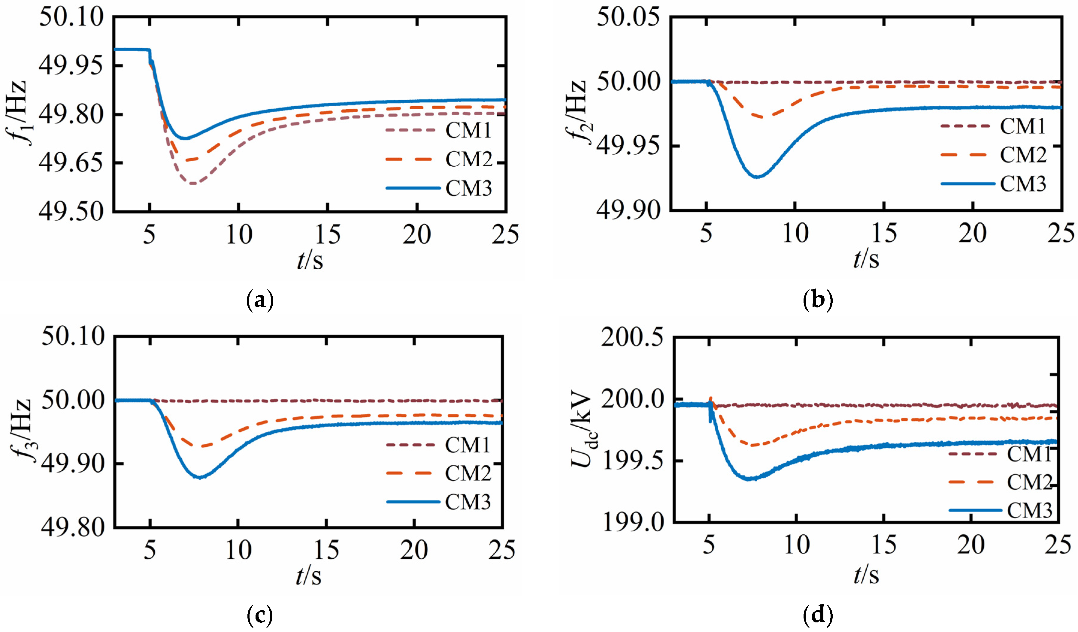
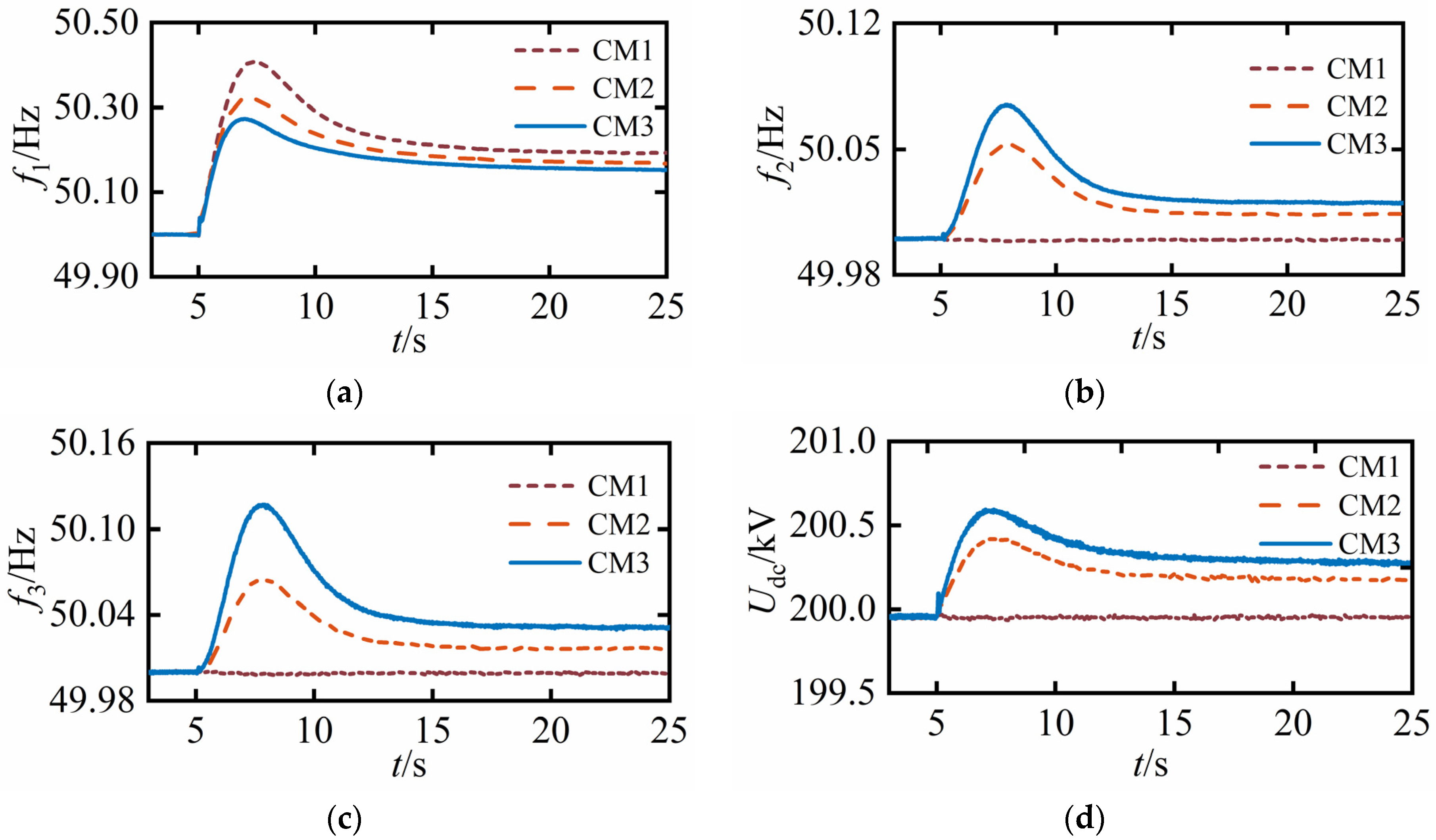
4.1. Sudden Increase of Power Grid Load

In this simulation, at t = 5 s, the AC1 load suddenly increased by 20 MW; the simulation results are shown below.
Let Δf1–Δf3 be the change in frequency of AC1–AC3, respectively, and ΔUdc be the change in DC voltage. As shown in Figure 9, the AC1 system frequency increased as the load increased. When CM1 was used, the VSC-MTDC system was unable to respond to the load fluctuation on the AC side, resulting in a large frequency fluctuation in the AC1 system; Δf1 was 0.41Hz, while Δf2 and Δf3 were both 0. When CM2 was used, the VSC station released the energy of the DC capacitor through the virtual inertia control to reduce the frequency deviation. At the same time, the reasonable distribution of the injected power of the VSC station can contribute to the rapid recovery of the AC1 system frequency; Δf1, Δf2 and Δf3 were 0.34 Hz, 0.03 Hz and 0.07 Hz, respectively. However, as the virtual inertia coefficient is fixed, the ability of the DC side to participate in frequency regulation was limited.
When CM3 was used, the virtual inertia coefficient was adaptively adjusted by the DC voltage deviation. When the DC voltage deviation was small, the inertia coefficient was increased to improve frequency support for the AC side; Δf1, Δf2 and Δf3 were 0.27 Hz, 0.07 Hz and 0.12 Hz, respectively. Although both f2 and f3 deviated from the rated operating point, each AC system could support each other’s power through the VSC-MTDC system. At the same time, because the power margin of VSC3 was larger than that of VSC2, the droop coefficient of VSC3 was smaller than that of VSC2, the power was larger than that of VSC2, and the frequency deviation was relatively large. As shown in Figure 9d, the deviation of the DC voltage under CM3 was the largest, but it was within a reasonable operating range.

4.2. Sudden Decrease of Power Grid Load

In this simulation, at t = 5 s, the AC1 load suddenly decreased by 20 MW; the simulation results are shown in Figure 10.
As can be seen from Figure 10, the system frequency increased as the load was reduced. When CM1 was used, the system frequency deviation was larger; Δf1 was 0.41 Hz, while both Δf2 and Δf3 were 0. When CM2 was used, Δf1, Δf2 and Δf3 were 0.32 Hz, 0.05 Hz and 0.06 Hz, respectively. Compared with CM1, the system frequency fluctuation was relatively small, effectively improving the system frequency response characteristics. When CM3 was used, the virtual inertia coefficient was adaptively adjusted according to the DC voltage deviation, and the inertia coefficient was increased to improve the frequency response when the DC voltage deviation was small; Δf1, Δf2 and Δf3 were 0.27 Hz, 0.07 Hz and 0.10 Hz, respectively. Additionally, the fastest frequency recovery occurred using CM3.

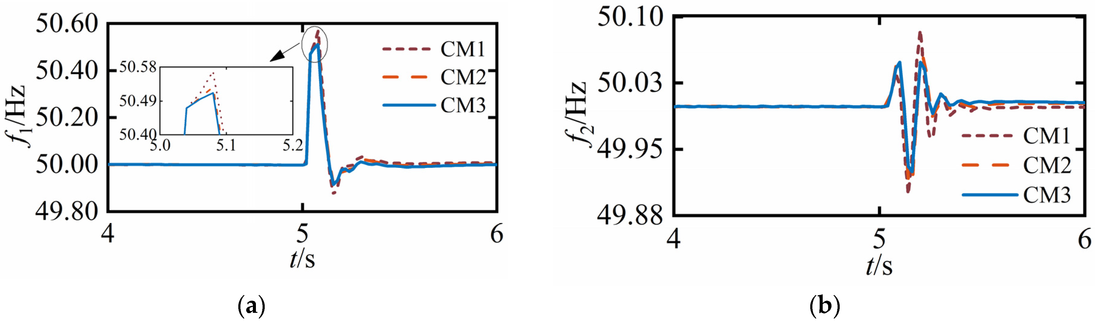
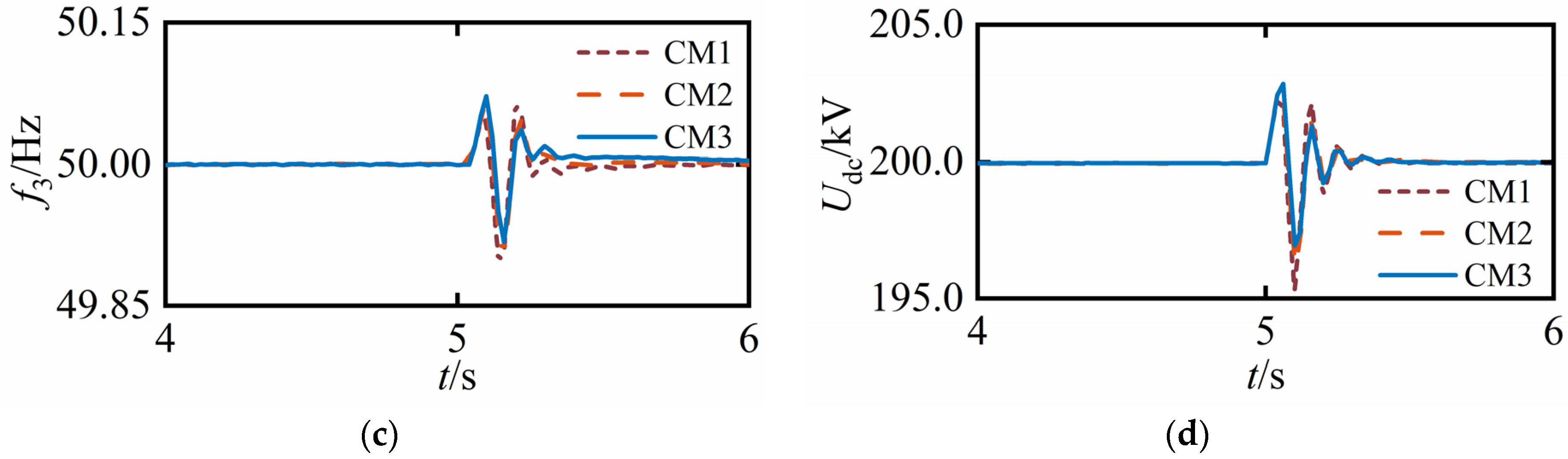
4.3. Single-Phase Short Circuit Fault in AC Power Grid

In this simulation, at t = 5 s, a single-phase short circuit fault occurred in the AC1 system, lasting for 0.05 s. The simulation results are shown in Figure 11.
As can be seen from Figure 11, after the fault of AC1, the grid frequency changed instantaneously, and then the frequency gradually returned to the rated value. When AC1 failed, the frequency fluctuation under CM3 was the smallest, CM2 was the second most effective and CM1 was the least effective; under CM3, Δf1, Δf2 and Δf3 were 0.57 Hz, 0.53 Hz and 0.51 Hz, respectively. When adopting the control strategy proposed by this paper, the DC voltage under transient fault can be reduced to a certain extent, which is conducive to the stability of DC voltage during fault recovery. At the same time, in the frequency recovery process, the recovery time under CM3 was short, the oscillation was small, and the frequency was more stable. The above simulation results illustrate that CM3 control facilitates frequency and DC voltage stability during transient fault recovery.

5. Conclusions

In this paper, a control strategy for VSC-MTDC systems based on adaptive virtual inertia control was proposed for the problem of frequency regulation and DC voltage stabilization after the AC system is disturbed, and the following conclusions were obtained.
(1)
Coupling AC frequency and DC voltage through virtual inertia control stabilizes the frequency and improves the frequency response characteristics.
(2)
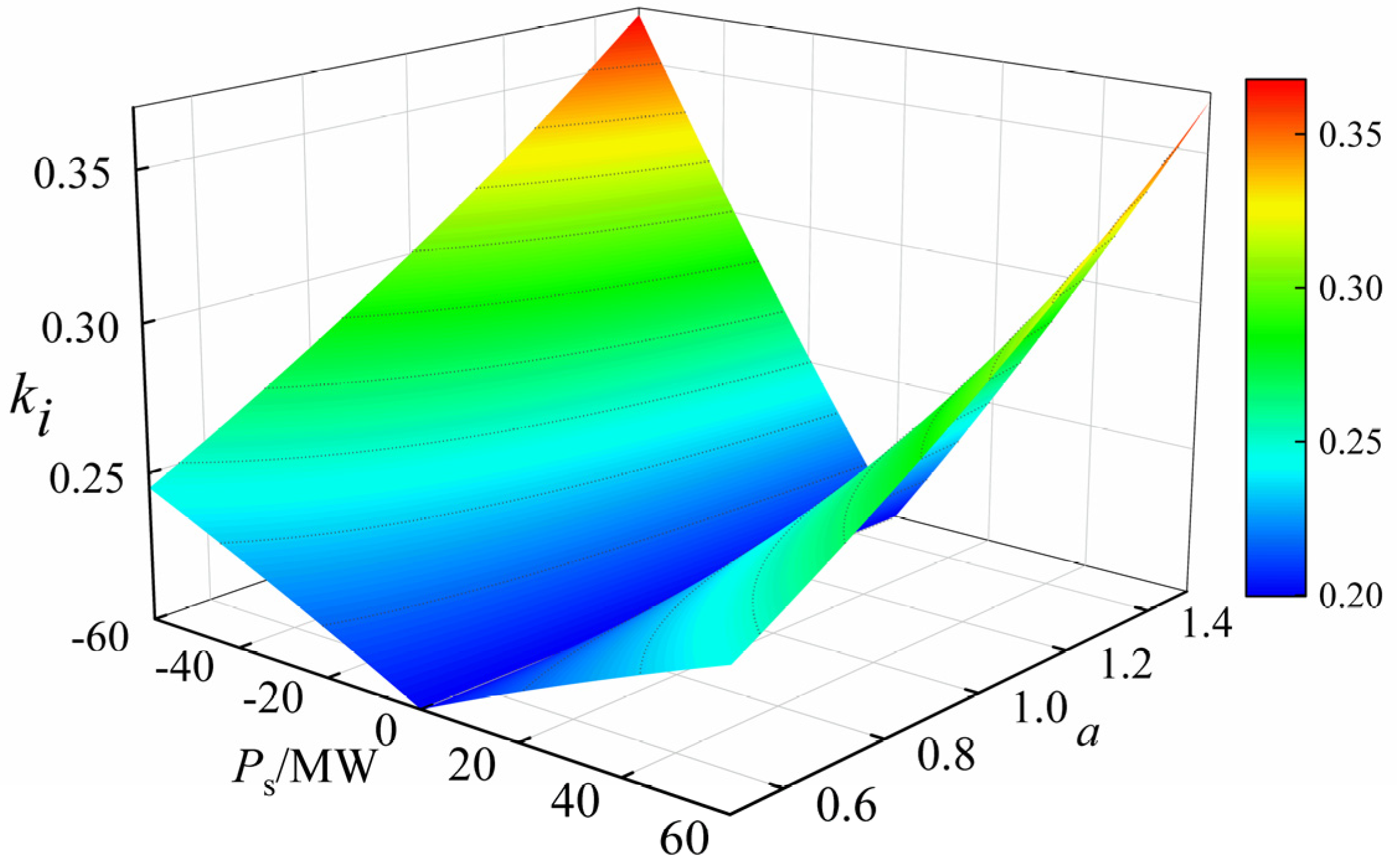
To solve the problem of the virtual inertia coefficient being constrained by the DC voltage deviation, the inertia coefficient is adaptively modified according to the DC voltage deviation. If the DC voltage deviation is small, the inertia coefficient is increased to obtain a better frequency response; on the contrary, the inertia coefficient is reduced to prevent the DC voltage from crossing the limit.
(3)
By adjusting the droop coefficient dynamically through the power margin of the VSC station and by distributing the unbalanced power appropriately, the DC voltage deviation can be reduced when the DC system is involved in AC frequency regulation.

Author Contributions

Conceptualization, C.L.; methodology, C.L.; validation, C.L.; writing—original draft preparation, X.Z.; visualization, P.H.; supervision, C.L. and Z.Z.; data curation, K.Z.; funding acquisition, C.L. All authors have read and agreed to the published version of the manuscript.

Funding

This research was funded by the Key Projects of Colleges and Universities in Henan Province (grant number 23A470011) and the Major Science and Technology Projects in Henan Province, (grant number 221100240500); and the Smart Grid Sichuan Provincial Key Laboratory 2022 Open Fund Project, (grant number 2022-IEPGKLSP-KFYB01).

Institutional Review Board Statement

Not applicable.

Informed Consent Statement

Not applicable.

Data Availability Statement

The data presented in this study are available on request from the corresponding.

Conflicts of Interest

The authors declare that there are no conflicts of interest that could be perceived as prejudicing the impartiality of the research reported.

References

  1. Alamri, B.; Hossain, M.A.; Asghar, M.J. Electric power network interconnection: A review on current status, future prospects and research direction. Electronics 2021, 10, 2179. [Google Scholar]
  2. Sun, P.; Wang, Y.; Khalid, M.; Gimenez, R.B.; Konstantinou, G. Steady-state power distribution in VSC-based MTDC systems and DC grids under mixed P/V and I/V droop control. Electr. Power Syst. Res. 2022, 214, 108798. [Google Scholar] [CrossRef]
  3. Radwan, A.A.A. Small-signal stability analysis of multi-terminal DC grids. Electronics 2019, 8, 130. [Google Scholar] [CrossRef]
  4. Liu, C.; Liu, H.; Jiang, S.; Zheng, L. A novel dynamic additional frequency control strategy for VSC-MTDC system. CSEE J. Power Energy Syst. 2023, 9, 645–658. [Google Scholar]
  5. Liu, Y.; Cui, H.; Liang, H.; He, J. Additional frequency adaptive droop control strategy considering DC voltage stability for VSC-MTDC system. Power Syst. Technol. 2020, 44, 2160–2168. [Google Scholar]
  6. Dolado, J.; Amenedo, J.L.R.; Arnaltes, S.; Garcia, J.E. Improving the inertial response of a grid-forming voltage source converter. Electronics 2022, 11, 2303. [Google Scholar] [CrossRef]
  7. Li, Z.; Wei, Z.; Zhan, R.; Li, Y.; Tang, Y.; Zhang, X. Frequency support control method for interconnected power systems using VSC-MTDC. IEEE Trans. Power Syst. 2021, 36, 2304–2313. [Google Scholar] [CrossRef]
  8. Zhu, R.; Li, X.; Ying, D. A frequency stability control strategy for interconnected VSC-MTDC transmission system. Power Syst. Technol. 2013, 38, 2729–2734. [Google Scholar]
  9. Liu, H.; Liu, C.; Jiang, S. Dynamic additional frequency control strategy for VSC-MTDC transmission system. Electr. Power Autom. Equip. 2022, 42, 164–170. [Google Scholar]
  10. Shadabi, H.; Kamwa, I. Dual Adaptive nonlinear droop control of VSC-MTDC system for improved transient stability and provision of primary frequency support. IEEE Access 2021, 9, 76806–76815. [Google Scholar] [CrossRef]
  11. Fang, J.; Li, H.; Tang, Y.; Blaabjerg, F. Distributed power system virtual inertia implemented by grid-connected power converters. IEEE Trans. Power Electron. 2018, 33, 8488–8499. [Google Scholar] [CrossRef]
  12. Zhu, J.; Booth, C.D.; Adam, G.P.; Roscoe, A.J.; Bright, C.G. Inertia emulation control strategy for VSC-HVDC transmission systems. IEEE Trans. Power Syst. 2013, 28, 1277–1287. [Google Scholar] [CrossRef]
  13. Liu, Y.; Hu, J.; Shi, J.; Yang, B. Adaptive integrated control strategy for MMC-MTDC transmission system considering dynamic frequency response and power sharing. Int. J. Electr. Power Energy Syst. 2023, 147, 108858. [Google Scholar] [CrossRef]
  14. Shen, Z.; Zhu, J.; Ge, L.; Bu, S.; Zhao, J.; Chung, C.; Li, X.; Wang, C. Variable-inertia emulation control scheme for VSC-HVDC transmission systems. IEEE Trans. Power Syst. 2022, 37, 629–639. [Google Scholar] [CrossRef]
  15. Ambia, M.N.; Meng, K.; Xiao, W.; Durra, A.A.; Dong, Z. Interactive grid synchronization based virtual synchronous generator control scheme on weak frid integration. IEEE Trans. Smart Grid 2022, 13, 4057–4071. [Google Scholar] [CrossRef]
  16. Yu, J.; Sun, W.; Yu, J.; Wang, Y. Virtual synchronous generator control of a grid connected inverter based on adaptive inertia. Power Syst. Prot. Control 2022, 50, 137–144. [Google Scholar]
  17. Ke, X.; Zhang, W.; Li, P.; Niu, S.; Sheng, S.; Yang, J. Fuzzy adaptive virtual inertia control for high wind power penetration system. Power Syst. Technol. 2020, 44, 2127–2136. [Google Scholar]
  18. Liu, Y.; Shi, J.; Liang, H.; Yang, B. Adaptive droop control strategy for VSC-MTDC system based on virtual inertial frequency regulation. Renew. Energy Resour. 2022, 40, 1081–1088. [Google Scholar]
  19. Zhu, R.; Li, X.; Wu, F. A novel droop control strategy taking into account the available headroom for VSC-MTDC system. J. Sichuan Univ. 2015, 47, 137–143. [Google Scholar]
  20. Mohammadi, F.; Nazri, G.A.; Saif, M. An improved droop based control strategy for MT-HVDC systems. Electronics 2020, 9, 87. [Google Scholar] [CrossRef]
  21. Meng, G.; Lu, Y.; Liu, H.; Ye, Y.; Sun, Y.; Tan, W. Adaptive droop coefficient and SOC equalization based primary frequency modulation control strategy of energy storage. Electronics 2021, 10, 2645. [Google Scholar] [CrossRef]
  22. Cheng, L.; Jin, G.; Wang, L.; Li, G.; Wang, Z.; Chen, J. Application scenarios and system design of medium-voltage DC distribution network. Autom. Electr. Power Syst. 2019, 43, 81–89. [Google Scholar]
  23. Peng, Q.; Liu, T.; Zhang, Y.; Li, B.; Tang, S. Adaptive droop control of VSC based DC grid considering power margin and system stability. Proc. Chin. Soc. Electr. Eng. 2018, 38, 3498–3506. [Google Scholar]
  24. Zeng, Q.; Li, X.; Zhang, L. Improved optimization droop control strategy taking into account the network loss and available headroom for VSC-MTDC system. High Volt. Eng. 2016, 42, 3117–3125. [Google Scholar]
  25. Zhang, X.; Shao, X.; Fu, Y.; Zhao, X.; Jiang, G. Transient voltage recovery control and stability criterion of VSC-based DC power grid. IEEE Trans. Power Syst. 2021, 36, 3496–3506. [Google Scholar] [CrossRef]
  26. Li, J.; Yang, M.; Li, J.; Xiao, Y.; Wang, J. Research on adaptive exponential droop control strategy for VSC-MTDC system. Electronics 2022, 11, 2788. [Google Scholar] [CrossRef]
  27. Li, B.; Li, Q.; Wang, Y.; Wen, W.; Li, B.; Xu, L. A novel method to determine droop coefficients of DC voltage control for VSC-MTDC system. IEEE Trans. Power Deliv. 2020, 35, 2196–2211. [Google Scholar] [CrossRef]
Figure 1. The topological structure of the VSC-MTDC system.
Electronics 12 02324 g001
Figure 2. VSC structure diagram.
Electronics 12 02324 g002
Figure 3. Comparison between VSC station and synchronous generator.
Electronics 12 02324 g003
Figure 4. Droop controller.
Electronics 12 02324 g004
Figure 5. Droop control operating characteristics.
Electronics 12 02324 g005
Figure 6. System control block diagram.
Electronics 12 02324 g006
Figure 7. VSC-station operation interval.
Electronics 12 02324 g007
Figure 8. kiPsα relation surface.
Electronics 12 02324 g008
Figure 9. AC1 load increase simulation results: (a) AC1 frequency; (b) AC2 frequency; (c) AC3 frequency; (d) system DC voltage.
Electronics 12 02324 g009
Figure 10. AC1 load decrease simulation results: (a) AC1 frequency; (b) AC2 frequency; (c) AC3 frequency; (d) system DC voltage.
Electronics 12 02324 g010
Figure 11. Single-phase short circuit simulation: (a) AC1 frequency; (b) AC2 frequency; (c) AC3 frequency; (d) System DC voltage.
Electronics 12 02324 g011aElectronics 12 02324 g011b
Table 1. Parameters of the simulation system.
No.Parameter NameParameter Value
1VSC1/VSC2/VSC3 capacity/Svsc60/60/120 MW
2System DC voltage/Udcref200 kV
3System AC voltage/Uac110 kV
4Number of DC capacitors/Nm2
5DC capacitance/C0.0015 F
6Rated frequency on AC side/fref50 Hz
7Initial droop coefficient/k1/k2/k30.2/0.2/0.1
Disclaimer/Publisher’s Note: The statements, opinions and data contained in all publications are solely those of the individual author(s) and contributor(s) and not of MDPI and/or the editor(s). MDPI and/or the editor(s) disclaim responsibility for any injury to people or property resulting from any ideas, methods, instructions or products referred to in the content.

