Article

A Novel Wearable Upper-Limb Rehabilitation Assistance Exoskeleton System Driven by Fluidic Muscle Actuators

1
Department of Mechanical Engineering, National Chung Hsing University, No. 145, Xingda Road, South District, Taichung City 40227, Taiwan
2
Department of Computer-Aided Industrial Design, Overseas Chinese University, No. 100, Chiao Kwang Road, Taichung City 40721, Taiwan
3
Department of Mechanical and Electro-Mechanical Engineering, Tamkang University, No. 151, Yingzhuan Road, Tamsui District, New Taipei City 25137, Taiwan
*
Author to whom correspondence should be addressed.
Electronics 2023, 12(1), 196; https://doi.org/10.3390/electronics12010196
Submission received: 19 November 2022 / Revised: 20 December 2022 / Accepted: 28 December 2022 / Published: 31 December 2022
(This article belongs to the Special Issue Design, Development and Testing of Wearable Devices)

Abstract

:
This paper proposed a novel design using a torsion spring mechanism with a single fluidic muscle actuator (FMA) to drive a joint with one degree-of-freedom (DOF) through a steel wire and a proportional pressure regulating valve (PRV). We developed a 4-DOF wearable upper-limb rehabilitation assistance exoskeleton system (WURAES) that is suitable for assisting in the rehabilitation of patients with upper-limb injuries. This system is safe, has a simple mechanism, and exhibits upper-limb motion compliance. The developed WURAES enables patients with upper-limb musculoskeletal injuries and neurological disorders to engage in rehabilitation exercises. Controlling the joint is difficult because of the time-varying hysteresis properties of the FMA and the nonlinear motion between standard extension and flexion. To solve this problem, a proxy-based output feedback sliding mode control (POFSC) was developed to provide appropriate rehabilitation assistance power for the upper-limb exoskeleton and to maintain smooth and safe contact between the WURAES and the patient. The POFSC enables the overdamped dynamic of the WURAES to recover motion to be aligned with the target trajectory without a significant error overshoot caused by actuator saturation. The experimental results indicate that the proposed POFSC can control the designed WURAES effectively. The POFSC can monitor the exoskeleton system’s total disturbance and unknown state online and adapt to the exterior environment to enhance the control capability of the designed system. The results indicate that a single FMA with a torsion spring module exhibits a control response similar to a dual FMA configuration.

Graphical Abstract

1. Introduction

The medical care of the elderly has grown in importance as the world’s population ages. Labor-related injuries have become more prevalent in recent years, mainly while performing repetitive, high-intensity activities with the arms, frequently resulting in fatigue and physical injuries. Additionally, according to a report published by the World Health Organization (WHO), nerve damage is the leading cause of permanent and acute disability. Approximately 5 million of the world’s 15 million stroke patients are currently disabled, putting a significant burden on their families and communities [1]. Patients with musculoskeletal injuries and neurological disorders can lose mobility, which can cause significant inconvenience in their lives. Physiotherapy and rehabilitation can effectively cure patients with such diseases and conditions. Traditional rehabilitation therapy is usually performed by paramedics and physical therapists. Repetitive and progressive functional exercises are required to help injured patients regain mobility [2,3,4,5]. However, the rehabilitation program planned by the physical therapist usually requires many passive manual activities for the patient and usually consumes a lot of time [6]. Therefore, more people are developing wearable upper-limb rehabilitation assistance exoskeleton systems (WURAES). The device can assist patients with injured limbs, lessen the physical strain on laborers, help the patient engage in everyday activities, and support rehabilitation and exercise. Powered exoskeletons can replace existing time-consuming rehabilitation exercises to lighten the workload on therapists.
The early WURAES were mainly motor-driven, had unwieldy structures, were expensive, and lacked flexibility. The assistive rehabilitation system must be lightweight, simple to use and carry, and have accurate control to ensure the patient’s safety. The fluidic muscle actuator (FMA), one of the many actuators in the rehabilitation system, has good flexibility and functions similarly to a human muscle while having an actuator that is lightweight, has good flexibility, high strength, high safety, and lower cost than motors. The FMA, which has a two-layer cylindrical structure, is also called the McKibben fluidic artificial muscle. Compared to conventional actuators, FMA has many specific benefits, including being clean, having a low cost, quick response times, high power-to-volume ratios, high power-to-weight ratios, and others. Its application range is wide [7,8]. FMA construction is covered with a rigid fiber material that is woven mesh-like, has a high strength, and is non-stretchable. The thin-walled elastic rubber tube that stores the air pressure is inside the FMA is fastened by metal parts at both ends to allow air intake and deflation. When the air pressure in the FMA increases, the inner rubber tube is expanded and deformed such that the rubber’s elasticity causes interior stress and radial inflation. Due to the extreme fiber restriction, the sealing of the fixing element, and the elasticity of the rubber, the axial direction produces contractile force. The length of the FMA is shortened and a pulling force is created. As the air pressure decreases, the FMA is stretched and returned to its original shape. The fluidic muscle’s tension during expansion and contraction is similar to animal or human muscle [9]. Ohta et al. [10] developed a 7-DOF composite exoskeleton design using FMAs and servo motors. Because the system must use many different sensors, the overall mechanical design of the system is too complicated and unsuitable for real applications. Tsagarakis et al. [11] utilized FMAs to drive the upper-limb exoskeleton system through antagonism. Six modules of FMAs and proportional pressure regulators (PRVs) [12] are required for their unilateral shoulder, elbow, and wrist joints. Therefore, the user’s burden is heavy and the cost is high, so it is unsuitable for rehabilitation patients. Chen et al. [13,14] used a single FMA for each WURAES joint in their design for four joints. All FMAs in the system are mounted on the back frame, giving the WURAES integrity. However, in this actuation manner, the shoulder joint cannot be expected to return to its initial position only due to the weight of the hand. A WURAES RUPERT was created by Sugar et al. [15] that utilized dual FMA to activate a single joint using the driving motion technique of antagonism to accomplish active assisted movement. Wei et al. [16] modified RUPERT IV with five degrees of freedom (5-DOF) and added the rotational DOF of the shoulder. Its FMAs, which are complicated structures weighing up to 95 kg and are positioned close to the upper limbs, require double the entire drive torque and reduce the patient’s range of motion. In addition to FMAs, in the latest development of fluidic actuators, Mao et al. [17] proposed a soft fluidic roller using a simple structure in 2022, which uses a voltage-driven oscillating fluid actuated by an EHD pump. That research is mainly applied to the rolling motion of robots, which has not been applied to the exoskeleton at present, and whether it applies to the flexion or extension of the exoskeleton remains to be further studied. In addition, in 2022, Mao et al. [18] also proposed a study of the applied single-layer and stacked EHD pumps to drive an eccentric actuator, which is still in the research stage. If the technology is mature enough, this method may be applied to exoskeletons.
Patient compliance and safety must be considered in the control of WURAES. The patient may feel unsafe if there is a vibration or momentary overshoot during the tracking response. Furthermore, when a larger error occurs, the wearable device will cause discomfort to the patient. More severe errors will make the patient unable to react in time to stop the device and force the affected limb to move excessively, causing severe injury or even life-threatening situations. Therefore, the WURAES controller must have over-damped properties to increase anti-vibration protection and avoid dangerous accidents. There are some differences between each patient with upper extremity injuries, such as weight and height. To overcome the uncertainty of WURAES, the controller design must adapt to these various changes. The general application of force and torque sensors for control cannot resolve uncertainty in the model and external disturbances [19]. This method cannot guarantee accuracy and patient safety at the same time. Usually, a larger controller gain will be set to ensure the control precision, resulting in a more significant overshoot. If the controller’s gain is low, it will have a sluggish, over-damped property and cannot respond quickly. Sliding mode control (SMC) is a control method that can quickly converge to an equilibrium point and maintain the system state on the sliding mode surface [20,21]. However, during the convergence process of the SMC, its jitter phenomenon will reduce the security performance. Proxy-based sliding mode control (PSMC) is a modified PID that combines the properties of the SMC and the proportional–integral–derivative (PID). PSMC can ensure continuous closed-loop dynamic behavior [22]. Due to its simple structure, PSMC has been used in nonlinear control by numerous previous studies [23,24,25] and is extensively applied in soft robotics (SoRo) since it guarantees accuracy and safety [26,27,28,29,30]. The stability analysis remains unresolved even though PSMC has been used in the control systems mentioned above. The extended PSMC was proposed assuming the external disturbances are bounded, and the system state is measurable [31]. The Lyapunov stability theorem can solve the stability problem of the original PSMC. Due to several patient differences, all system states and disturbances cannot be instantly obtained. Therefore, it will be challenging to apply extended PSMC to WURAES. The Extended state observer (ESO) can evaluate all system states and disturbances at the same time, solving difficult-to-measure problems [32]. However, there are too many parameters to set in ESO, making the setup difficult. The linear extended state observer (LESO) [33,34] is based on bandwidth parameterization methods and high-gain ESO. This method can effectively reduce the number of parameters. In this research, WURAES is a human-machine coupled system, and different kinds of external disturbances make it impossible to obtain all the system states. To this end, the control method of this study combines a modified PSMC and a LESO to accomplish precision control of the upper-limb exoskeleton and guarantee the safety of the patient and the WURAES.
This paper presents a novel WURAES with four actuated joints (4-DOF). Each joint mechanism module mainly includes a torsion spring pulled by a single FMA through a steel wire. Compared to the general upper-limb exoskeleton using FMAs [11], this research just used half the FMAs and half the PRVs. The overall driving mechanism will be more direct, simpler, and low-cost. Simultaneously, this study using the structure of the torsion springs directly solves the issue that the joint mechanism cannot return to the initial position only via the weight of the hand [13,14]. To understand a user’s action intention when using an upper-limb exoskeleton, Trigili et al. [35] applied surface electromyography (sEMG) to detect the upper-limb exoskeleton motion rapidly. Their system detected upper-limb motion intention 88 to 134 ms earlier than the kinematic onset. Zhuang et al. [36] used a controller based on sEMG to improve human–exoskeleton synchronization and a controller based on torque sensors to ensure reduced muscle activity. In the present study, electromyography (EMG) signals of arm muscles were measured using an sEMG bracelet on the patient’s forearm. These signals were transmitted through Bluetooth for identifying the patient’s action intention, and different gestures were used for rehabilitation mode switching. Moreover, a proxy-based output feedback sliding mode control (POFSC) was designed for the controller field. Under normal conditions, this control solution can maintain high-accuracy tracking. When a large error occurs in the system, it can be controlled through overdamping to achieve the expected result of the compliant operation.
The rest of this paper is organized as follows. Section 2 provides an introduction to the structure of the proposed WURAES. Section 3 describes the mechanics model of the developed system. Section 4 provides details regarding the design of the proposed POFSC and the results of the stability analysis. Section 5 presents the results of experiments performed to validate the developed WURAES. Finally, Section 6 provides the conclusions of this study.

2. Mechanism Design

To assist injured patients in regaining their mobility through repetitive and progressive rehabilitation training while reducing the burden on therapists, a safe, lightweight, low-cost, easy-to-operate, and easy-to-wear assistive device was developed in the present study. Dual FMAs, which have different designs to those of most FMAs used in SoRo, are generally used in methods in which a pulley and steel wire are used to activate a joint. The dual FMA antagonistic mechanism is extensively applied for joint actuation in SoRo. Because the design of dual FMAs requires the cooperation of two sets of PRVs and two sets of related mechanisms, the overall mechanical structure is bulky and has high production and material costs [30]. Consequently, this study aimed to develop a novel WURAES for patients with upper-limb injuries and the elderly to assist their upper-limb mobility training during rehabilitation therapy. The drive joint of the designed WURAES primarily consists of a torsion spring module connected to a single FMA by a steel wire, and this joint is controlled using a PRV. A pulley module and dual FMAs can be replaced by the torsion spring mechanism and a single FMA. Under a suitable control strategy, a matched FMA and torsion spring can produce the same actuation results as those produced using dual FMAs. A single FMA-driven mechanism requires half the number of FMAs and PRVs required by a dual FMA mechanism; thus, a single FMA-driven mechanism reduces the total cost, weight, and volume of a WURAES. The design of a WURAES should be as close as possible to the anatomy of the human arm and must match the motion of the human arm. However, detailed designs result in complex and bulky upper-limb exoskeleton mechanisms. As illustrated in Figure 1, a four-DOF WURAES was developed in this study. The primary function of this system was the extension and flexion of the shoulder and elbow joints of the arm on both sides. Figure 2 shows a photograph of the designed WURAES. Its primary frame material was low-cost aluminum alloy, which is lightweight, and its structure consisted of four joint modules: rotation pulleys with a diameter of 60 mm, torsion springs, FMAs with two shoulder joints (length: 310 mm), and FMAs with two elbow joints (length: 400 mm). The maximal shrinkage rate of an FMA was 25% of its length. An extendable mechanism was developed to adapt to the various dimensions of human arms. In accordance with the proportionate relationships between different human body parts [37], it was used to calculate the design sizes of the forearm, upper arm, and shoulder mechanisms. Each joint module included a single FMA, torsion spring, and high-resolution absolute encoder for monitoring the rotation angle of the joint in motion.
The structure of the designed WURAES is similar to that of a human upper-limb. In a joint module of this WURAES, an FMA is inflated and deflated to simulate the bone’s flexion motion, which results in joint rotation. The unilateral WURAES is composed of two main joint rotation modules to assist the movement of the shoulder and elbow joints. As shown in Figure 3, a torsion spring is designed to be deployed in each joint for energy storage. This spring replaces the mechanism comprising a dual FMA configuration and pulley. When the power is not activated, a torsion spring with a certain preload angle is installed in the pulley at one end of the wire. Because of the torsion spring, the joint can return to its initial position. Pressure is provided to the FMA through the PRV when the power is switched on. The FMA expands and shortens under pressure and drives the rotation of the pulley through the wire, which results in joint extension and flexion. Figure 4 shows the specifications of the torsion spring used in the designed WURAES. Encoders are mounted on single FMA-driven joints to determine the joint angles. Moreover, a digital channel sends the encoders’ measurement signals to the embedded controller. On the basis of the angle trajectory tracking error, the POFSC determines the control voltage of the PRV, which adjusts the pressure to drive the FMA and achieves closed-loop angle trajectory tracking control for the single FMA-driven joints. The hardware specifications of the WURAES are shown in Figure 4. The system controller utilizes the embedded system. The control algorithm and signal measurement tool used in the experiments were primarily developed in LabVIEW. We used the WURAES to verify the controller’s performance and the feasibility of the designed mechanism (Figure 2).

3. System Mechanics Model

Forward and inverse kinematics were used to analyze the developed WURAES, and this system’s dynamic equations and mathematical model were established using the Lagrange method.

3.1. Forward Kinematic Analysis

The Denavit–Hartenberg (DH) parameter coordinate transformation method [38,39] was used to define the relationship between the orientation and the rotational position of the links of the designed WURAES. In the initial system position, the upper arm is stretched outward and is in a straight line with the forearm (Figure 5). The 4-DOF is located on the four axes. The single axis has only one rotational DOF. Table 1 presents the structural parameters of each link. The parameter α i 1 denotes the rotation angle around the x i 1 -axis, i is the movement distance along the x i 1 -axis, ϑ i is the rotation angle around the z i -axis, and d i is the movement distance along the z i -axis.
The following coordinate transformation matrix can be used to transform the coordinate system i 1 into the coordinate system i :
T i i 1 = R o t ( x , α i 1 ) T r a n s ( x , i 1 ) R o t ( z , ϑ i ) T r a n s ( z , d i ) = [ c i s i s i c α i 1 c i c α i 1                 0 i 1 s α i 1 d i s α i 1 s i s α i 1 c i s α i 1     0 0         c α i 1           d i c α i 1 0 1 ]
where i = 1 6 , c i = cos ϑ i , s i = sin ϑ i , c i α i 1 = cos α i 1 , and s i α i 1 = sin α i 1 . The parameters presented in Table 1 are substituted into Equation (1) to obtain the matrix operation formula for the joints. Subsequently, the homogeneous transformation matrices of the coordinates are multiplied with each other in sequence, and the orientation and position relationship matrix at the endpoint of the mechanism of the designed WURAES relative to the base coordinates can be expressed as follows:
T 6 0 = T 1 0 T 2 1 T 3 2 T 4 3 T 5 4 T 6 5 = [ h 11 h 12 h 21 h 22         h 13 D x h 23 D y h 31 h 32 0 0         h 33 D z 0 1 ]
where h 11 = c 1 c 2 c 34 s 1 s 34 , h 12 = c 1 c 2 s 34 s 1 c 34 , h 13 = c 1 s 2 , h 21 = s 1 c 2 c 34 + c 1 s 34 , h 22 = s 1 c 2 s 34 c 1 c 34 , h 23 = s 1 s 2 , h 31 = s 2 c 34 + s 34 , h 32 = s 2 s 34 + c 34 , h 33 = c 2 , D x = 1 + c 1 2 + c 1 c 2 3 + ( s 1 s 3 + c 1 c 2 c 3 ) 4 + ( c 1 c 2 c 34 s 1 s 34 ) 5 + c 1 s 2 d 2 is the displacement of the upper-limb exoskeleton in the direction of abduction and adduction, D y = s 1 2 + s 1 c 2 3 + ( c 1 s 3 + s 1 c 2 c 3 ) 4 + ( s 1 c 2 c 34 + c 1 s 34 ) 5 + s 1 s 2 d 2 is the displacement of the upper-limb exoskeleton in the vertical direction of motion, and D z = s 2 3 + ( s 3 s 2 c 3 ) 4 + ( s 2 c 34 + s 34 ) 5 d 1 + c 2 d 2 is the displacement of the upper-limb exoskeleton in the forward and backward swing directions.

3.2. Inverse Kinematic Analysis

In terms of inverse kinematics, the rotation angle of each joint is solved inversely from the known position D x , D y , D z at the end of the link in the upper-limb exoskeleton. On the basis of Equation (2), h 13 = c 1 s 2 , h 23 = s 1 s 2 , and h 33 = c 2 ; thus, the following equations are obtained:
s 2 = h 13 2 + h 23 2 ,
{ ϑ 2 = tan 1 ( h 13 2 + h 23 2 h 33 ) , h 33 > 0 ϑ 2 = π + tan 1 ( h 13 2 + h 23 2 h 33 ) , h 33 < 0 ,
ϑ 1 = tan 1 ( s 1 c 1 ) ,
where s 1 = h 23 / s 2 and c 1 = h 13 / s 2 . The parameter ϑ 3 is solved according to the characteristics of the homogeneous transformation as follows:
( 3 0 ) T ( 1 ) ( 6 0 ) T = ( 6 3 ) T
[ c 1 c 2 s 1 c 2 s 2 ( c 1 c 2 1 + c 2 2 + s 2 d 1 ) c 1 s 2 s 1 s 2 c 2 c 1 s 2 1 + s 2 2 c 2 d 1 s 1 c 1 0 s 1 1 0 0 0 1 ] [ h 11 h 12 h 21 h 22         h 13 D x h 23 D y h 31 h 32 0 0         h 33 D z 0 1 ] = [ c 34 s 34 0 3 + c 3 4 + c 34 5 0 0 1 d 2 s 34 c 34 0 s 3 4 + s 34 5 0 0 0 1 ]
From Equation (7), the following equation is obtained:
s 34 = s 1 h 11 + c 1 h 21
s 3 4 + s 34 5 = s 1 D x + c 1 D y + s 1 1
c 34 = s 1 h 12 + c 1 h 22
3 + c 3 4 + c 34 5 = c 1 c 2 D x + s 1 c 2 D y s 2 D z ( c 1 c 2 1 + c 2 2 + s 2 d 1 )
By substituting Equation (8) into Equation (9), Equation (12) is obtained. Moreover, by substituting Equation (10) into Equation (11), Equation (13) is obtained.
s 3 = s 1 D x + c 1 D y + s 1 1 ( s 1 h 11 + c 1 h 21 ) 5 4
c 3 = c 1 c 2 D x + s 1 c 2 D y s 2 D z ( c 1 c 2 1 + c 2 2 + s 2 d 1 ) 3 ( s 1 h 12 + c 1 h 22 ) 5 4
From Equations (12) and (13), the following equation is obtained:
ϑ 3 = tan 1 ( s 3 c 3 )
The same method is used to solve for ϑ 4 according to the properties of the homogeneous transformation.
T 4 0 1 T 6 0 = T 6 4   .
Equations (16)–(18) can be obtained from Equation (15).
s 4 = ( c 1 c 2 c 3 s 1 c 3 ) h 11 + ( c 1 c 3 s 1 c 2 s 3 ) h 21 + s 2 s 3 h 31
c 4 = (   c 1 c 2 c 3 s 1 c 3 ) h 11 + ( s 1 c 2 c 3 c 1 s 3 ) h 21 s 2 c 3 h 31
ϑ 4 = tan 1 ( s 4 c 4 )
Equations (4), (5), (14), and (18) can be used to determine the angles of each joint analyzed using inverse kinematics.

3.3. Kinematic Model Validation

The sampling positions ( D y , D z ) are substituted into the derived inverse kinematic equation, providing the rotation angles ( ϑ 3 , ϑ 4 ) of the shoulder joint and elbow joint. Subsequently, the forward kinematic equation is substituted to obtain the new end position of the trajectory. ( D y * , D z * ) , ( D y , D z ) , and ( D y * , D z * ) are compared to verify the correctness of the model of forward and reverse motion. The process for verifying the forward and inverse kinematics is illustrated in Figure 6. As presented in Figure 7, the results for forward and inverse kinematics reveal considerable overlap, which proves that the model of forward and inverse kinematics is correct.

3.4. System Dynamics Model

The designed WURAES assists only with the extension and flexion of the shoulder and elbow joints. The other actions represent passive DOFs, which follow the movement of the patient’s upper limbs. Figure 8 displays the dynamic model of the designed unilateral WURAES. In this figure, m u and a u = 3 are the upper arm’s mass and length, respectively, m f and a f = 4 are the forearm’s mass and length, respectively, θ u = ϑ 3 is the shoulder joint’s extension and flexion angle, and θ f = ϑ 4 is the elbow joint’s extension and flexion angle. The following equation describes the relationships between the moments acting on the joints, the torques of the torsion springs, and the pulling forces of the FMAs:
{ τ u + T s = F u R s τ f + T e = F f R e ,
where τ u and τ f are the total moments at the shoulder and elbow joints, respectively; T s and T e are the torques acting on the shoulder and elbow joints, respectively, from the torsion springs; F u and F f are the pulling forces acting on the shoulder and elbow joints, respectively, from the FMAs; and R s and R e represent the radii of the pulleys at the shoulder and elbow joints, respectively.
The static mathematical model of an FMA can be expressed using the following equation after considering the elasticity of the rubber cylinder, the friction force of the woven fiber web, the friction force between the woven fiber web and the rubber cylinder, and the radian at both ends of the FMA [40]:
F F M A = r 1 2 r 2 ( P i + Δ P ) [ υ ( 1 - ε ) 2 - ρ ] + F A ( t ) F B ( t ) n tan ϕ F C ( t ) ,
where υ = 3 π D i 2 / ( 4 tan 2 ϕ i ) ,   ρ = π D i 2 / ( 4 sin 2 ϕ i ) ,   F A ( t ) = π E T t r D r ( t ) ( L F M A ( t ) L m ) / L m , and F B ( t ) = E T t r L F M A ( t ) ( D r ( t ) D r i ) / D r i . The other parameters used in the system model are listed in Table 2.
Another external force acting on each joint is the torque generated by the torsion spring. This torque is used to counteract the pulling force produced by the FMA. This antagonism drives the joint’s rotation to cause the extension or flexion of the upper arm or forearm. The torque generated by the torsion spring is calculated as follows [41]:
{ θ u ( t ) = 64 T s ( t ) D T N b d T 4 E S 180 π ,   shoulder   joint θ f ( t ) = 64 T e ( t ) D T N b d T 4 E S 180 π ,   elbow   joint .
Equation (21) can be rearranged as follows:
{ T s ( t ) = θ u ( t ) d T 4 E S π 11520 D T N b ,   shoulder   joint T e ( t ) = θ f ( t ) d T 4 E S π 11520 D T N b ,   elbow   joint ,
where D T is the mean coil diameter of the torsion spring, d T is the wire diameter of the torsion spring, E S is the modulus of elasticity of the torsion spring material, and N b is the number of turns of the free spring. As displayed in Figure 8, the unilateral arm of the designed WURAES has two movable joints. The extension and flexion of each joint are achieved through the generation of rotational motion through antagonism by the FMA and torsion spring. The shoulder and elbow joints are independent systems and can control the joint angle separately. Therefore, the dynamic analysis of single joints is conducted, and the mechanical system displayed in Figure 8 is subdivided into a shoulder joint dynamic model (Figure 9) and an elbow joint dynamic model (Figure 10). The other nonconservative forces in the system, such as the frictional force and the machining accuracy of the designed mechanism, are regarded as external disturbances. The dynamic model of a single joint is expressed in Equation (23).
{ I u θ ¨ u = ( F u R s T s ) ( M u ) g L u sin Θ u + d s u , shoulder   joint I f θ ¨ f = ( F f R e T e ) ( M f ) g L f sin Θ f + d e f , elbow   joint   ,
where L u denotes the distance from the shoulder joint to the center of mass of the upper arm and forearm, L f refers to the distance between the elbow joint and the forearm’s center of mass, I u is the total moment of inertia relative to the center of mass of the upper arm and forearm, I f is the forearm’s moment of inertia relative to its center of mass, M u = m u + m f , M f = m f , g is the acceleration due to gravity, Θ u = θ u , Θ f = θ u + θ f , and d s i is the uncertain external disturbance for each joint.
Because the state equations of the shoulder and elbow joints are derived in the same manner, only the detailed derivation of the state equation of the shoulder joint is described in this paper. By defining the state x u = [ x 1 u x 2 u ] T = [ θ u θ ˙ u ] T , the single FMA-driven shoulder joint’s state equation can be expressed as follows:
{ x ˙ 1 u = x 2 u x ˙ 2 u = ( F u R s T s ) ( M u ) g L u sin Θ u + d s u I u ,
By substituting Equations (20) and (22) into Equation (24), the following equation is obtained:
{ x ˙ 1 u = x 2 u x ˙ 2 u = { R s [ r 1 2 r 2 ( P i + Δ P ) [ υ ( 1 - ε ) 2 - ρ ] + F A ( t ) F B ( t ) n tan ϕ F C ( t ) ] θ u ( t ) d T 4 E S π 11,520 D T N b } M u g L u sin Θ u + d s u I u = R s [ r 1 2 r 2 [ υ ( 1 - ε ) 2 - ρ ] P i + F A ( t ) F B ( t ) n tan ϕ ] θ u ( t ) d T 4 E S π 11,520 D T N b M u g L u sin Θ u I u + R s r 1 2 r 2 [ υ ( 1 - ε ) 2 - ρ ] K e v ( t ) I u + d s u R s F C ( t ) I u = f ( x u ) + G ( x u ) v ( t ) + q ( t ) ,
where f ( x u ) = { R s [ r 1 2 r 2 [ υ ( 1 - ε ) 2 - ρ ] P i + F A ( t ) F B ( t ) / ( n tan ϕ ) ] θ u ( t ) d T 4 E S π / ( 11520 D T N b ) M u g L u sin Θ u } / I u is the nonlinear dynamic function of the single FMA-driven shoulder joint, G ( x u ) = R s r 1 2 r 2 [ υ ( 1 - ε ) 2 - ρ ] K e / I u is the control gain, v ( t ) = Δ P / K e is the control voltage of the PRV, K e is the voltage conversion coefficient of the voltage device, and q ( t ) = [ d s u R s F C ( t ) ] / I u is the disturbance.

4. Controller Design

PSMCs have been efficiently used in many fields, including SoRo, because of their accurate tracking ability, ease of implementation, and safe comeback when the device is subjected to external interference. However, the stability problem of these control methods has not been adequately resolved [42]. Furthermore, most previous relevant studies have assumed that all system states can be measured, and they have focused on proving that closed-loop dynamics are passively recompensated disturbances [31]. Therefore, in the designed WURAES, a POFSC is used to solve the problems of not measuring all states of the system and the interference effects of various patients. A LESO regards nonlinear states, different disturbances, and uncertainty, as extended states and can simultaneously evaluate the total disturbances and all system states [43]. This observer enhances the ease of derivation and simplifies the procedure for determining the stability of a dynamic system. The design of the developed POFSC and the stability analysis of this control for a single FMA-driven joint of the designed WURAES are described in the following text.

4.1. Design and Analysis of a LESO

The designed POFSC resembles a sliding mode controller and applies a second-order system [42]. Only a single FMA-driven joint is analyzed because the shoulder joint is driven similarly to the elbow joint. The extended state of Equation (25), F f ( x u ) + ( G ( x u ) ) G 0 ) v ( t ) + q ( t ) , is used to derive the following relationship. The extended state vector is defined as X = [ θ u θ ˙ u F ] T = [ X 1 X 2 X 3 ] R 3 , and the following equation is then obtained:
{ X ˙ 1 = X 2 X ˙ 2 = X 3 + G 0 v ( t ) X ˙ 3 = γ ,
where G 0 is the nominal value of G ( x u ) and X ˙ 3 = γ is the rate of change of the total disturbance. In accordance with Equation (26), the LESO of a single FMA-driven joint of the designed WURAES is expressed as follows [29]:
{ X ^ ˙ 1 = X ^ 2 Ω 1 ( X ^ 1 X 1 ) X ^ ˙ 2 = X ^ 3 Ω 2 ( X ^ 1 X 1 ) + G 0 v ( t ) X ^ ˙ 3 = Ω 3 ( X ^ 1 X 1 )
where X ^ = [ X ^ 1 X ^ 2 X ^ 3 ] T represents the observed state vector and Ω i ( i = 1 , 2 , 3 ) represents the tunable observer gains. The estimation error of the aforementioned LESO is expressed as follows:
{ ˜ 1 = X ^ 1 X 1 ˜ 2 = X ^ 2 X 2 ˜ 3 = X ^ 3 X 3 .
The dynamic equations of the estimation errors of the LESO and system states can be described as follows by taking the derivative of Equation (28) with respect to time and substituting Equations (26) and (27):
{ ˜ ˙ 1 = ˜ 2 Ω 1 ˜ 1 ˜ ˙ 2 = ˜ 3 Ω 2 ˜ 1 ˜ ˙ 3 = Ω 3 ˜ 1 γ .
Equation (29) can be presented in the matrix form as follows:
ε ˜ ˙ = A ε ˜ + B γ ,
where ε ˜ ˙ = [ ˜ ˙ 1 ˜ ˙ 2 ˜ ˙ 3 ] T , A = [ Ω 1 1 0 Ω 2 0 1 Ω 3 0 0 ] , ε ˜ = [ ˜ 1 ˜ 2 ˜ 3 ] T , and B = [ 0 0 1 ] T .
In terms of proving the ability of the LESO to observe and estimate, the gain of the LESO is selected according to the conditions [ Ω 1 , Ω 2 , Ω 3 ] = [ φ 1 ω 0 , φ 2 ω 0 2 , φ 3 ω 0 3 ] ,   ω 0 > 0 , and φ i > 0   ( i = 1 , 2 , 3 ) . The characteristic polynomial of Equation (30) can then be written in the following form:
| λ I A | = | s + φ 1 ω 0 1 0 φ 2 ω 0 2 s 1 φ 3 ω 0 3 0 s | = 0
After calculation and rearrangement, the following equation is obtained:
λ ( s ) = s 3 + φ 1 ω 0 s 2 + φ 2 ω 0 2 s + φ 3 ω 0 3 .
By choosing λ ( s ) = ( s + ω 0 ) 3 , we can obtain φ 1 = 3 ,   φ 2 = 3 , and φ 3 = 1 , where ω 0 is the bandwidth of the LESO, which is an adjustable parameter that affects the estimation ability of the LESO. When ω 0 is larger, the LESO can converge to the actual system states faster, and the estimation error is smaller. However, in actual application, the size of the observer bandwidth ω 0 is affected by the sampling step size and noise, and enlarging this bandwidth arbitrarily is impossible [44]. Define β i = ω 0 3 i ˜ i ( i = 1 , 2 , 3 ) , β = [ β 1 β 2 β 3 ] T , where
{ β 1 = ω 0 2 ˜ 1 = ω 0 2 ( X ^ 1 X 1 ) β 2 = ω 0 ˜ 2 = ω 0 ( X ^ 2 X 2 ) β 3 = ˜ 3 = ( X ^ 3 X 3 )   ,
because
β ˙ 1 ω 0 = ω 0 ( X ^ ˙ 1 X ˙ 1 ) = ω 0 ( X ^ 2 Ω 1 ( X ^ 1 X 1 ) X 2 ) = ω 0 ( X ^ 2 X 2 φ 1 ω 0 ( X ^ 1 X 1 ) ) = ω 0 2 φ 1 ( X ^ 1 X 1 ) + ω 0 ( X ^ 2 X 2 ) = φ 1 β 1 + β 2 .
Similarly, the following equation can be obtained:
β ˙ 2 ω 0 = φ 2 β 1 + β 3 β ˙ 3 ω 0 = φ 3 β 1 + ( γ ) ω 0
The observation error state equation can be expressed in the following matrix form:
β ˙ ω 0 = φ β + B γ ω 0 ,
where β ˙ = [ β ˙ 1 β ˙ 2 β ˙ 3 ] T , φ = [ φ 1 1 0 φ 2 0 1 φ 3 0 0 ] . Because the matrix φ is a Hurwitz matrix, for any given symmetric positive definite matrix P , a positive definite matrix L exists, such that φ T L + L φ = P . In this case, Equation (37) can be selected as the Lyapunov candidate function.
V L E S O = β T L β .
Assuming that the rate of change of the total disturbance of the system is bounded, there exists Q > 0 , such that | γ | Q . By taking the derivative of Equation (37) with respect to time, the following equation is obtained:
V ˙ L E S O = ω 0 β T P β + 2 β T L B γ ω 0 λ min ( P ) β 2 + 2 Q λ max ( L ) β
For Equation (37), there exists λ min ( L ) β 2 V L E S O λ max ( L ) β 2 ; thus, the following equation is obtained:
V L E S O λ max ( L ) β 2 V L E S O λ min ( L )
By substituting Equation (39) into Equation (38), the following equation is obtained:
V ˙ L E S O ω 0 λ min ( P ) λ max ( L ) V L E S O + 2 Q λ max ( L ) λ min ( L ) V L E S O
Let R = V L E S O , then R ˙ = V ˙ L E S O / ( 2 V L E S O ) , and Equation (40) can be rewritten as follows:
R ˙ ω 0 λ min ( P ) 2 λ max ( L ) R + Q λ max ( L ) λ min ( L )
On the basis of the Gronwall–Bellman inequality [45], Equation (41) can be rewritten as follows:
R [ 2 Q λ max 2 ( L ) ω 0 λ min ( L ) λ min ( P ) R ( t 0 ) ] e [ ω 0 λ min ( P ) 2 λ max ( L ) ( t t 0 ) ] + 2 Q λ max 2 ( L ) ω 0 λ min ( L ) λ min ( P )
From Equations (39) and (42), the following equation can be obtained:
β V L E S O λ min ( L ) 2 Q λ max 2 ( L ) ω 0 λ min ( L ) λ min ( P ) = W e ω 0 ,   ( t )
where W e = 2 Q λ max 2 ( L ) / [ λ min ( L ) λ min ( P ) ] > 0 . Equation (43) indicates that the convergence speed of the observer estimation error β is related to the bandwidth ω 0 of the observer. A higher value of ω 0 is associated with a faster error convergence rate. In the present study, the same eigenvalue ω 0 was chosen. Consequently, the bandwidth ω 0 of the observer becomes the only adjustable parameter in the LESO, which reduces the computations involved in parameter tuning [46].
lim ω 0 β = 0

4.2. Proxy-Based Output Feedback Sliding Mode Control

Figure 11 illustrates the principle of the proposed POFSC. In this figure, θ ^ q s h o u l d e r and θ ^ q e l b o w are an estimate of the angular positions of the shoulder and elbow joints, respectively, θ q s h o u l d e r and θ q e l b o w are the proxy angular positions of the shoulder and elbow joints, respectively, and θ d s h o u l d e r and θ d e l b o w are the desired target angular positions of the shoulder and elbow joints, respectively. To connect the real controlled object and a virtual object (called a proxy), the POFSC uses a virtual coupling scheme that integrates proportional–derivative (PD) type controllers with a LESO (PD + LESO). Consequently, the PD + LESO controller produces the interaction force F p i ( i = s h o u l d e r , e l b o w ) between the proxy and the actuator. Moreover, at this time, the SMC with the LESO (SMC + LESO) applies the force F POFSC i ( j = s h o u l d e r , e l b o w ) to control the proxy to track the desired assistance target. The unilateral arm of the designed WURAES can be considered as two independent single FMA-driven joints with coupling disturbances. Figure 11 illustrates the overall control strategy for the unilateral arm of the designed WURAES, in which two POFSCs are used for independently controlling the internal pressure of two FMAs for the shoulder and elbow joints. The shoulder and elbow joints on both sides of the WURAES use the POFSCs for movement control, respectively. Therefore, the symbols used in the following derivations will ignore the labels of the shoulder and elbow joints.
Firstly, define the two sliding surface equations before the POFSC is designed, as follows:
{ S p = λ n a ( θ d θ p ) + θ ˙ d θ ˙ p S q = λ n a ( θ d θ ^ q ) + θ ˙ d θ ^ ˙ q ,
where θ p and θ d are the proxy angular position and desired angular position, respectively, θ ˙ p and θ ˙ d are the rates of change of the proxy and desired angular positions, respectively, θ ^ q is an estimate of the actual angular position of the controlled object, and λ n a > 0 is the designed control gain. The SMC + LESO controller F P O F S C expressed in Equation (46) is used to control the virtual proxy.
F P O F S C = { sgn ( S p ) k p ( θ p θ ^ q ) + I p m θ ¨ d + I p m λ n a ( θ ˙ d θ ˙ p ) k d ( θ ˙ p θ ^ ˙ q ) + 1 G 0 [ F ^ + k p ( θ p θ ^ q ) + k d ( θ ˙ p θ ^ ˙ q ) + λ n a ( θ ˙ d θ ^ ˙ q ) + θ ¨ d ] } / R θ
where > 0 is the control gain, sgn ( ) is the signum function, I p m is the proxy’s moment of inertia, and R θ is the action radius of the angular displacement caused by the applied force. Furthermore, a novel PD + LESO controller is designed, as shown in Equation (47), to generate the virtual coupling force F p .
F p = 1 R θ G 0 [ F ^ + k p ( θ p θ ^ q ) + k d ( θ ˙ p θ ^ ˙ q ) + λ n a ( θ ˙ d θ ^ ˙ q ) + θ ¨ d ] ,
where F p is the total disturbance estimated by the LESO for the single FMA-driven joint, and k p and k d represent the PD controller’s gain. The motion equation for the proxy shown in Figure 11 can be determined using Newton’s second law of motion.
F P O F S C -   F p = I p m θ ¨ p / R θ
The virtual proxy’s motion must be computer-simulated when the controller is performed straightly with Equations (46) and (47). In accordance with the study of Kikuuwe et al. [22], who set the moment of inertia of the proxy as 0 in practical applications, the proxy moment of inertia in Equation (48) is set as 0 in the present study. Subsequently, by substituting Equations (46) and (47) into Equation (48), the following equation is obtained:
I p m θ ¨ p = sgn ( S p ) k p ( θ p θ ^ q ) + I p m θ ¨ d + I p m λ n a ( θ ˙ d θ ˙ p ) k d ( θ ˙ p θ ^ ˙ q ) .
Equation (49) can be rewritten as follows:
θ ˙ p = 1 k d [ sgn ( δ ) k p ( θ p θ ^ q ) + k d θ ^ ˙ q ] ,
where δ = k d ( θ ˙ d θ ^ ˙ q ) + k d λ n a ( θ d θ p ) + k p ( θ p θ ^ q ) . By substituting Equation (50) into Equation (47), the POFSC can be used for controlling a single FMA-driven joint, as expressed in the following equation:
F P O F S C = F p = F ^ + λ n a ( θ ˙ d θ ^ ˙ q ) + θ ¨ d + sgn ( δ ) R θ G 0 ,
where F P O F S C is the POFSC’s realistic output force. The POFSC can be considered an expanded PD control and an alternative SMC solution. Because of the proxy and virtual PD + LESO coupling, the POFSC combines responsive and accurate tracking during regular operation (as determined by k p and k d ) and achieves smooth, slow, and safe recovery from high position errors (determined by λ n a and ). Consequently, the POFSC enables precise tracking and provides interactive safety. Figure 12 depicts the proposed POFSC’s control block diagram for a single FMA-driven joint.

4.3. Stability Analysis

Lyapunov’s stability theory is used to analyze the stability of the proposed POFSC in WURAES control. The following Lyapunov candidate function is selected to represent the following equation:
V = 1 2 I p m S p 2 + 1 2 S q 2 + 1 2 ( k p + k d λ n a ) ( θ p θ ^ q ) 2 .
By differentiating both sides of Equation (52) with respect to time and substituting Equations (42) and (49) into V ˙ , the following equation is obtained:
V ˙ = S p I p m [ θ ¨ d θ ¨ p + λ n a ( θ ˙ d θ ˙ p ) ] + S q [ θ ¨ d θ ^ ¨ q + λ n a ( θ ˙ d θ ^ ˙ q ) ] + ( k p + k d λ n a ) ( θ p θ ^ q ) ( θ ˙ p θ ^ ˙ q ) = S p [ sgn ( S p ) + k p ( θ p θ ^ q ) + k d ( θ ˙ p θ ^ ˙ q ) ] + S q [ θ ¨ d θ ¨ q ˜ ¨ q + λ n a ( θ ˙ d θ ^ ˙ q ) ] + k p ( θ p θ ^ q ) ( θ ˙ p θ ^ ˙ q ) + k d λ n a ( θ p θ ^ q ) ( θ ˙ p θ ^ ˙ q ) = S p [ sgn ( S p ) + k p ( θ p θ ^ q ) + k d ( θ ˙ p θ ^ ˙ q ) ] + S q [ θ ¨ d F G 0 v ˜ ¨ q + λ n a ( θ ˙ d θ ^ ˙ q ) ] + k p ( θ p θ ^ q ) ( θ ˙ p θ ^ ˙ q ) + k d λ n a ( θ p θ ^ q ) ( θ ˙ p θ ^ ˙ q ) = S p [ sgn ( S p ) + k p ( θ p θ ^ q ) + k d ( θ ˙ p θ ^ ˙ q ) ] + S q [ F + F ^ ˜ ¨ q k p ( θ p θ ^ q ) k d ( θ ˙ p θ ^ ˙ q ) ] + k p ( θ p θ ^ q ) ( θ ˙ p θ ^ ˙ q ) + k d λ n a ( θ p θ ^ q ) ( θ ˙ p θ ^ ˙ q ) = | S p | k p λ n a ( θ p θ ^ q ) 2 k d ( θ ˙ p θ ^ ˙ q ) 2 0 .
Equations (52) and (53) indicate that the Lyapunov candidate function V is a positive definite function and that V ˙ is a negative semidefinite function. The term A denotes a nonsingular matrix with positive eigenvalues, and the total disturbance F is bounded (as per the assumption); thus, the estimate states X ^ X as t and ω 0 . Therefore, Lyapunov’s method demonstrates the stability of a single FMA-driven joint around the equilibrium θ e = [ S p ( 0 ) ,   S q ( 0 ) ,   θ p ( 0 ) θ q ( 0 ) ] = 0 under the compensation provided by the proposed POFSC.

5. Experimental Results and Discussion

Control experiments were conducted to validate the assistance effect of the designed WURAES. The rehabilitation assistance provided by the single FMA-driven joints of the designed WURAES must be smooth and slow to provide safe and comfortable contact between the patient and the device. In the experiments, the trajectory was planned using a fifth-order polynomial function to avoid excessive transient response oscillation caused by control voltage saturation resulting from a significant error [47]. The fifth-order polynomial equations for the angle θ d ( t ) , angular velocity θ ˙ d ( t ) , and angular acceleration θ ¨ d ( t ) applied in the movement control of the designed WURAES can be expressed as follows:
{ θ d ( t ) = g 0 + g 1 t + g 2 t 2 + g 3 t 3 + g 4 t 4 + g 5 t 5 θ ˙ d ( t ) = g 1 + 2 g 2 t + 3 g 3 t 2 + 4 g 4 t 3 + 5 g 5 t 4 θ ¨ d ( t ) = 2 g 2 + 6 g 3 t + 12 g 4 t 2 + 20 g 5 t 3 .
The initial condition ( t = 0 ) and terminal condition ( t = t e ) are expressed in Equation (55).
{ θ d ( 0 ) = g 0 θ ˙ d ( 0 ) = g 1 θ ¨ d ( 0 ) = 2 g 2 θ d ( t e ) = g 0 + g 1 t e + g 2 t e 2 + g 3 t e 3 + g 4 t e 4 + g 5 t e 5   θ ˙ d ( t e ) = g 1 + 2 g 2 t e + 3 g 3 t e 2 + 4 g 4 t e 3 + 5 g 5 t e 4 θ ¨ d ( t e ) = 2 g 2 + 6 g 3 t e + 12 g 4 t e 2 + 20 g 5 t e 3
The unique solution of the six coefficients of the fifth-order polynomial equation can be obtained from the six known initial and terminal conditions.
{ g 0 = θ d ( 0 ) g 1 = Χ ˙ d ( 0 ) g 2 = Χ ¨ d ( 0 ) 2 g 3 = 1 2 t e 3 [ 20 ( θ d ( t e ) θ d ( 0 ) ) ( 8 θ ˙ d ( t e ) + 12 θ ˙ d ( 0 ) ) t e ( 3 θ ¨ d ( 0 ) θ ¨ d ( t e ) ) t e 2 ] g 4 = 1 2 t e 4 [ 30 ( θ d ( t e ) θ d ( 0 ) ) + ( 14 θ ˙ d ( t e ) + 16 θ ˙ d ( 0 ) ) t e ( 3 θ ¨ d ( 0 ) 2 θ ¨ d ( t e ) ) t e 2 ] g 5 = 1 2 t e 5 [ 12 ( θ d ( t e ) θ d ( 0 ) ) 6 ( θ ˙ d ( t e ) + θ ˙ d ( 0 ) ) t e ( θ ¨ d ( 0 ) θ ¨ d ( t e ) ) t e 2 ] .
Using Equation (56), the fifth-order polynomial function θ d ( t ) = g 0 + g 1 t + g 2 t 2 + g 3 t 3 + g 4 t 4 + g 5 t 5 for the period t e and initial time t = 0 can be obtained. Because of the initial conditions θ ˙ d ( 0 ) = 0 and θ ¨ d ( 0 ) = 0 , as well as the terminal conditions θ ˙ d ( t e ) = 0 and θ ¨ d ( t e ) = 0 , the fifth-order polynomial function is represented as follows:
θ d ( t ) = { ( θ d ( t e ) θ d ( 0 ) ) ( r e ) 3 [ 6 ( r e ) 2 15 ( r e ) + 10 ] , 0 r e 1 θ d ( t e ) θ d ( 0 ) , r e > 1 ,
where r e = t / t e , t e denotes the time required to reach the rehabilitation assistance target, θ d ( t ) represents the rehabilitation assistance path, and t represents the operating time. The sampling frequency was set as 200 Hz in this study.
This article has proposed related mechanical structures and experimental equipment in Figure 4 (Section 2). The sensors and control core of the developed WURAES include the following devices: the absolute rotary encoder, sEMG bracelet, and embedded controller. The absolute rotary encoder uses the German Kübler model 8.2470.1212.G121. After the system is restarted, the value measured by the encoder is the real-time angle without initialization. The data output of the encoder is stimulated by a pair of differential time pulse trains, which can reduce noise interference. The encoding of the data adopts Gray code, characterized by the difference of each adjacent number with only one bit, which can improve the system’s stability and reduce the possibility of errors. The sEMG bracelet uses the Thalmic Labs model Myo-Armband, which will be described in Section 5.3. The embedded controller uses the myRIO 1900 embedded controller produced by National Instruments (NI) as the core of the overall system control. This controller has the advantages of being small in size, lightweight, and having powerful computing functions, which can meet the needs of this study. The myRIO 1900 Embedded Controller is equipped with a Zynq integrated System on a Chip (SoC) and a Xilinx Z-7010 FPGA chip designed by Xilinx. The central processor is an ARM Cortex-A9 embedded system chip with ten analog input channels, six analog output channels, and forty digital input and output channels. This system is equipped with a real-time operating system for real-time computing needs and can perform complex mathematical operations. The FPGA (Field Programmable Gate Array) allows users to customize higher-speed task calculations with a maximum speed of 25 ns and includes a Wi-Fi chip to provide wireless network communication to transmit data.

5.1. Path-Tracking Positioning Control for the Shoulder Joint

Shoulder flexion movement is driven by the pulling force produced by an FMA on the wire on the shoulder joint of the designed WURAES. In general, the flexion angle of the shoulder joint should not be too large, so that excessive load on the shoulder joint is avoided. Separate simulations were conducted for the following two common shoulder flexion angles of 30° and 45°. Table 3 presents the parameters of the control system in the experiments conducted to track the shoulder joint’s path. Figure 13 displays the experimental results of path-tracking positioning control obtained for the shoulder flexion angles of 30° and 45°. Table 4 presents the error in the path-tracking positioning control for the shoulder joint. As presented in Table 4, the maximum error in the path-tracking positioning control for the shoulder joint was less than 1.3°, with the root-mean-square deviation being less than 0.5° The results confirmed that an excellent control effect was achieved in path-tracking positioning for the shoulder joint under the compensation provided by the proposed POFSC.

5.2. Path-Tracking Positioning Control for the Elbow Joint

The flexion movement of the elbow joint of the designed WURAES is the same as that of the shoulder joint. In general, the flexion angle of the elbow joint is larger than that of the shoulder joint. Separate simulations were conducted for the common elbow flexion angles of 60° and 75°. Table 5 presents the parameters of the control system in the experiments conducted to track the elbow joint’s path. Figure 14 displays the experimental results of path-tracking positioning control at elbow flexion angles of 60° and 75°. Table 6 presents the error in the path-tracking positioning control for the elbow joint. As presented in Table 6, the maximum error in the path-tracking positioning for the elbow joint was less than 1.4°, with the root-mean-square deviation being less than 0.6°. The results indicated that an excellent control effect was achieved in path-tracking positioning for the elbow joint under the compensation provided by the proposed POFSC.

5.3. Performance Tests and Comparisons of Angular Path-Tracking

To verify the angle path-tracking effect of the POFSC, using the PID control method, re-do the same angle path-tracking of the shoulder and elbow joints, then compare the results with the angular path-tracking results of the POFSC. The controller parameters of the PID experiment are shown in Table 7. Figure 15 and Figure 16 compare the two control methods for the shoulder joint at 30° and 45°, respectively. Table 8 presents that the maximum control error of the POFSC at 30° was within 0.94°, and the root-mean-square deviation was within 0.3°; the maximum control error of the PID was within 2.53°, and the root-mean-square deviation was within 0.67°. Table 9 presents that the maximum control error of the POFSC at 45° was within 1.29°, and the root-mean-square deviation was within 0.41°; the maximum control error of the PID was within 5.22°, and the root-mean-square deviation was within 1.84°. Figure 17 and Figure 18 compare the two control methods for the elbow joint at 60° and 75°, respectively. Table 10 presents that the maximum control error of the POFSC at 60° was within 1.35°, and the root-mean-square deviation was within 0.52°; the maximum control error of the PID was within 3.42°, and the root-mean-square deviation was within 1.49°. Table 11 presents that the maximum control error of the POFSC at 75° was within 0.88°, and the root-mean-square deviation was within 0.44°; the maximum control error of the PID was within 4.23°, and the root-mean-square deviation was within 1.92°. This experimental result shows that although the two methods can finally reach the target angle, the error of the POFSC method proposed in this study is smaller than that of the PID control method in the tracking process. In addition, the results of this experiment also demonstrate the most important property of the POFSC: a smooth response to desired angular path-tracking. During the experiment, the path-tracking also almost fit the target trajectory. When using the POFSC, the angular path-tracking is continuous and smooth, which is stable without a jitter for the patient’s experience. However, due to the large error of the PID control method, generating a jittery trajectory in the process of approaching the target is easy to produce uncomfortable and unsafe feelings for patients.

5.4. Safety Tests and Comparisons

Consider possible emergencies that may occur in the wearable exoskeleton device system, such as the user’s confrontational action or the sudden unexpected impact of external force. These situations may cause a significant change in angle and pose a danger. Therefore, this safety test is used to simulate the situation where the angles of the joint change drastically in an instant. Firstly, use the fifth-order trajectory to track the shoulder joint for 5 s and reach 45°. After obtaining the target, stay for 5 s, and the angle suddenly drops to 20°. Then, verify whether the control system is safe according to the system response. Figure 19 shows the trajectory control experiment results for simulating the shoulder joint’s instantaneous angle changes. According to the experimental results, it can be found that when the angle changes suddenly and instantaneously, the system response can be smoothly tracked by the POFSC. However, the PID shows that the angles oscillate up and down before converging and approaching the more widely varying angles. From the experimental results, it can also be verified that the POFSC has a damping stabilization effect when the error is large.

5.5. User Intent Detection Using the sEMG Bracelet

The WURAES is a human-machine coupling system. To ensure the coordination, stability, and flexibility of the WURAES system, it is necessary to reduce human–machine confrontation as much as possible. The accuracy of human motion intention recognition has a crucial influence on controlling the WURAES. Most existing research on human intention recognition is based on physical information, which is only an indirect reflection of human intention and is not conducive to real-time control. Physiological signals are the most direct reflection of the human body’s intentions. Most current methods predict the patient’s motion intention by measuring the patient’s bio-myoelectric signal. The traditional electrode patch method will be subject to significant noise interference, and the sticking position and skin humidity will significantly affect the measurement results. These problems will interfere with the patient’s rehabilitation training.
In this study, to allow patients to switch between different rehabilitation modes easily or to determine users’ action intentions, different gestures can be set to represent rehabilitation modes or action intentions in the designed system. EMG signals are measured for arm muscles using an sEMG bracelet (Myo-Armband) worn on the patient’s forearm. The sEMG bracelet uses eight sensors that wrap around the arm in a close-fitting mode to detect the myoelectric signals of the arm muscles. Due to the characteristics of being close-fitting and wrapping around the arm, the problems of the aforementioned electrode patches being easily disturbed and poorly positioned have been resolved. The measured sEMG signals are transmitted to the controller through Bluetooth. After their decoding and analysis, the signals are matched with the set gestures and are used to control the upper-limb exoskeleton to perform corresponding actions. The sEMG bracelet is in the form of a wristband that fits over the patient’s forearm, and the sensor system used in the designed WURAES contains eight sEMG channels. The sEMG bracelet can be expanded to fit the arm size and provides rotational symmetry to prevent motion artifacts. The designed WURAES must be calibrated for different patient gestures before use. The signal recognition program of the sEMG converts the signals obtained by the eight channels of the sEMG bracelet into millivolts (mV), as seen in Equation (58) [48].
E ¯ = S ¯ V ¯ R ¯ ,
where E ¯ represents the sEMG data, S ¯ is the output of the sEMG bracelet, V ¯ is 3.3 V, and R ¯ is the resolution (8 bits = 256). The procedure for evaluating the sEMG signals of a patient’s gesture is described in the following text. First, the sEMG bracelet is worn on the patient’s forearm for recording sEMG signals at a frequency of 200 Hz. Second, the data from the eight channels of the bracelet are filtered following the guidelines of the Surface ElectroMyoGraphy for the Non-Invasive Assessment of Muscles project (Butterworth, fifth-order, 50 Hz) [49]. Third, the characteristic waveform of the patient’s gesture is extracted using the root-mean-square (RMS) feature extraction method after the filtered data have been rectified and normalized [50,51,52].
To detect the action intentions of users of the designed WURAES, sEMG signals from arm muscles were detected using the sEMG bracelet. The sensors in this sEMG bracelet detected different hand movements and generated signals from different muscles. The detected signals were then transmitted to the embedded controller through Bluetooth. After the analysis of these signals, the WURAES was controlled to realize the actions desired by the users. First, basic settings for general users, such as those related to starting, lifting, and dropping the shoulder and elbow joints (Figure 20), were implemented. Alternatively, the target angle was set according to the user’s needs, such as the desired stretch position. These actions corresponded to five different gestures (Figure 21). To simplify the gestures to facilitate experimentation and user operation, the essential and desired actions were tested with the same gestures. Second, the users were provided instructions related to gestures and exercises, and the correspondence between gestures and signals was recorded and fine-tuned. Finally, the users could operate the designed WURAES by themselves.
Among the above five gestures, gesture 1 is fist, gesture 2 is spread, gesture 3 is wave-in, gesture 4 is wave-out, and gesture 5 is double-tap. Figure 22, Figure 23, Figure 24 and Figure 25 show the captured EMG signals and RMS of the first four gestures maintained for 10 s, respectively. Figure 26 shows the EMG and RMS of gesture 5, which performed six double taps in 10 s. The above EMG signal graphs show that the eight EMG signal graphs are different for the five gestures, which can be used to identify the user’s gestures. This study employs a utility program provided by the original manufacturer to determine various user gestures to confirm the user’s action intention.
When wearing the sEMG bracelet, one of the left or right hands can be selected according to the user’s habits. In this experiment, the sEMG bracelet was worn on the left forearm, the designed WURAES was worn on the right arm, and the motion intention of the hand was detected (Figure 27). The experimental results indicated that the designed WURAES successfully detected the intention of the users through the sEMG bracelet sensor according to the set gestures and realized the required corresponding actions. The basic action and desired action experiments are illustrated in Figure 28, Figure 29, Figure 30, Figure 31, Figure 32, Figure 33 and Figure 34, respectively.

6. Conclusions

In this study, a four-DOF WURAES was designed to aid the rehabilitation of the shoulder and elbow joints. In this system, a single FMA with a torsion spring module drives each joint with 1-DOF through a steel wire. The adopted joint mechanism requires half the number of FMAs and PRVs needed for the traditional dual FMA mechanism, which pulls the pulley through an antagonistic method. The WURAES is a simple design that is safe, lightweight, low-cost, and has portability advantages. This system exhibits upper-limb motion compliance. The WURAES can provide a novel wearable upper-limb exoskeleton system for patients with upper-limb musculoskeletal injuries and neurological disorders to help the patients rehabilitate, practice, and assist at work. A POFSC is proposed to control the nonlinear joint movements of the WURAES between extension and flexion and the time-varying properties of FMAs. This control method can provide correct rehabilitation assistance for the upper-limb exoskeleton and maintain smoothness and safety between the WURAES and the patient. The POFSC enables the WURAES overdamped dynamic recovery motion to the target trajectory without significant error overshoot due to actuator saturation. The experimental results indicate that the proposed POFSC can observe the system’s total disturbance and unknown state online and effectively overcome the influences of the nonlinear and inertial changes of a single FMA mechanism, thereby achieving high safety and an excellent compensation effect. The results demonstrate that a single FMA with a torsion spring module can obtain a control response similar to the dual FMA mechanism. Moreover, sEMG signals can successfully identify users’ intent, enabling patients to switch between several rehabilitation assistance modes easily and quickly.

7. Patents

The pneumatic-driven robotic gait training system developed has obtained a Taiwanese invention patent and a US invention patent. These are (1) an exoskeleton apparatus driven by pneumatic artificial muscle with functions of upper-limb assist and rehabilitation training, Taiwanese patent number i584801; (2) an exoskeleton apparatus driven by pneumatic artificial muscle with functions of upper-limb assist and rehabilitation training, US patent number us 10,420,695 b2; and (3) an exoskeleton apparatus driven by pneumatic artificial muscle with functions of upper-limb assist and rehabilitation training, China patent number ZL 2017 1 0240416.4.

Author Contributions

Conceptualization, L.-W.L., S.-J.C. and H.-R.C.; methodology, L.-W.L., H.-R.C. and I.-H.L.; software, L.-W.L. and I.-H.L.; validation, L.-W.L., H.-R.C. and S.-J.C.; formal analysis, L.-W.L., H.-R.C. and I.-H.L.; investigation, L.-W.L. and H.-R.C.; resources, L.-W.L. and I.-H.L.; data curation, L.-W.L.; writing—original draft preparation, H.-R.C. and L.-W.L.; writing—review and editing, L.-W.L. and I.-H.L.; supervision, L.-W.L. and S.-J.C.; project administration, L.-W.L.; funding acquisition, L.-W.L. and S.-J.C. All authors have read and agreed to the published version of the manuscript.

Funding

This research has financial support from (1) the Ministry of Science and Technology, R.O.C., grant (MOST 111-2221-E-005-088-) and (2) the Ministry of Science and Technology, R.O.C., grant (MOST 110-2221-E-005-083-).

Institutional Review Board Statement

The study was conducted in accordance with the Declaration of Helsinki and approved by the Institutional Review Board (or Ethics Committee) of Yuanpei University of Medical Technology Institutional Review Board (protocol code YPU-IRB-1080606 and the date of approval was 21 June 2019) for studies involving humans.

Informed Consent Statement

Not applicable.

Data Availability Statement

Not applicable.

Acknowledgments

This research is sponsored by the Ministry of Science and Technology, Taiwan, R.O.C., under grant Nos. MOST 105-2221-E-262-009-, MOST 111-2221-E-005-088-, and MOST 110-2221-E-005-083-.

Conflicts of Interest

The authors declare no conflict of interest.

References

  1. WHO. Stroke, Cerebrovascular Accident, 2022. World Health Organization, Eastern Mediterranean. 2022. Available online: http://www.emro.who.int/health-topics/stroke-cerebrovascular-accident/index.html (accessed on 6 August 2022).
  2. Veerbeek, J.M.; Langbroek-Amersfoort, A.C.; Van Wegen, E.E.; Meskers, C.G.; Kwakkel, G. Effects of Robot-Assisted Therapy for the Upper Limb After Stroke. Neurorehabil. Neural Repair. 2017, 31, 107–121. [Google Scholar] [CrossRef] [PubMed]
  3. Maciejasz, P.; Eschweiler, J.; Gerlach-Hahn, K.; Jansen-Troy, A.; Leonhardt, S. A survey on robotic devices for upper limb rehabilitation. J. Neuroeng. Rehabil. 2014, 11, 1–29. [Google Scholar] [CrossRef] [PubMed] [Green Version]
  4. Gopura, R.A.R.C.; Bandara, D.S.V.; Kiguchi, K.; Mann, G.K.I. Developments in hardware systems of active upper-limb exoskeleton robots: A review. Robot. Auto. Syst. 2016, 75, 203–220. [Google Scholar] [CrossRef]
  5. Cafolla, D.; Russo, M.; Carbone, G. CUBE, a cable-driven device for limb rehabilitation. J. Bionic Eng. 2019, 16, 492–502. [Google Scholar] [CrossRef]
  6. Sanjuan, J.D.; Castillo, A.D.; Padilla, M.A.; Quintero, M.C.; Gutierrez, E.E.; Sampayo, I.P.; Hernandez, J.R.; Rahman, M.H. Cable driven exoskeleton for upper-limb rehabilitation: Adesign review. Robot. Auton. Syst. 2020, 126, 103445. [Google Scholar] [CrossRef]
  7. Chou, C.P.; Hannaford, B. Measurement and modeling of McKibben pneumatic artificial muscles. IEEE Trans. Robot. Autom. 1996, 12, 90–102. [Google Scholar] [CrossRef] [Green Version]
  8. Caldwell, D.G.; Medrano-Cerda, G.A.; Goodwin, M. Control of pneumatic muscle actuators. IEEE Control Syst. Mag. 1995, 15, 40–48. [Google Scholar]
  9. Andrikopoulos, G.; Nikolakopoulos, G.; Manesis, S. A Survey on applications of Pneumatic Artificial Muscles. In Proceedings of the Mediterranean Conference on Control and Automation (MED), Aquis Corfu Holiday Palace, Corfu, Greece, 20–23 June 2011; pp. 1439–1446. [Google Scholar]
  10. Ohta, P.; Valle, L.; King, J.; Low, K.; Yi, J.; Atkeson, C.G.; Park, Y.L. Design of a lightweight soft robotic arm using pneumatic artificial muscles and inflatable sleeves. Soft Robot. 2018, 5, 204–215. [Google Scholar] [CrossRef] [Green Version]
  11. Tsagarakis, N.G.; Caldwell, D.G. Development and Control of a ‘Soft-Actuated’ Exoskeleton for Use in Physiotherapy and Training. Auton. Robot. 2003, 15, 21–33. [Google Scholar] [CrossRef]
  12. Sárosi, J. New approximation algorithm for the force of fluidic muscles. In Proceedings of the 7th IEEE International Symposium on Applied Computational Intelligence and Informatics (SACI), Timisoara, Romania, 24–26 May 2012; pp. 229–233. [Google Scholar]
  13. Chen, C.T.; Lien, W.Y.; Chen, C.T.; Twu, M.J.; Wu, Y.C. Dynamic Modeling and Motion Control of a Cable-Driven Robotic Exoskeleton With Pneumatic Artificial Muscle Actuators. IEEE Access 2020, 8, 149796–149807. [Google Scholar] [CrossRef]
  14. Chen, C.T.; Lien, W.Y.; Chen, C.T.; Wu, Y.C. Implementation of an upper-limb exoskeleton robot driven by pneumatic muscleactuators for rehabilitation. InActuators 2020, 9, 106. [Google Scholar] [CrossRef]
  15. Sugar, T.G.; He, J.; Koeneman, E.J.; Koeneman, J.B.; Herman, R.; Huang, H.; Schultz, R.S.; Herring, D.E.; Wanberg, J.; Balasubramanian, S.; et al. Design and control of RUPERT: A device for roboticupper extremity repetitive therapy. IEEE Trans. Neural Syst. Rehabil. Eng. 2007, 15, 336–346. [Google Scholar] [CrossRef] [PubMed]
  16. Wei, R.; Balasubramanian, S.; Xu, L.; He, J. Adaptive iterative learning control design for RUPERT IV. In Proceedings of the 2nd IEEE RAS—EMBS International Conference on Biomedical Robotics and Biomechatronics, Scottsdale, AZ, USA, 19–22 October 2008; pp. 647–652. [Google Scholar]
  17. Mao, Z.; Asai, Y.; Yamanoi, A.; Seki, Y.; Wiranata, A.; Minaminosono, A. Fluidic rolling robot using voltage-driven oscillating liquid. Smart Mater. Struct. 2022, 31, 105006. [Google Scholar] [CrossRef]
  18. Mao, Z.; Asai, Y.; Wiranata, A.; Kong, D.Q.; Man, J. Eccentric actuator driven by stacked electrohydrodynamic pumps. J. Zhejiang Univ. Sci. A 2022, 23, 329–334. [Google Scholar] [CrossRef]
  19. Chen, S.H.; Lien, W.M.; Wang, W.W.; Lee, G.D.; Hsu, L.C.; Lee, K.-W.; Lin, S.-Y.; Lin, C.-H.; Fu, L.-C.; Lai, J.-S.; et al. Assistive Control System for Upper Limb Rehabilitation Robot. IEEE Trans. Neural Syst. Rehabil. Eng. 2016, 24, 1199–1209. [Google Scholar] [CrossRef]
  20. Benamor, A.; Messaoud, H. Robust adaptive sliding mode control for uncertain systems with unknown time-varying delay input. ISA Trans. 2018, 79, 1–12. [Google Scholar] [CrossRef] [PubMed]
  21. Pan, Y.; Yang, C.; Pan, L.; Yu, H. Integral sliding mode control: Performance, modification, and improvement. IEEE Trans. Ind. Inform. 2018, 14, 3087–3096. [Google Scholar] [CrossRef]
  22. Kikuuwe, R.; Yasukouchi, S.; Fujimoto, H.; Yamamoto, M. Proxy-based sliding mode control: A safer extension of PID position control. IEEE Trans. Robot. 2010, 26, 670–683. [Google Scholar] [CrossRef]
  23. Gu, G.Y.; Zhu, L.M.; Su, C.Y.; Ding, H.; Fatikow, S. Proxy-based sliding-mode tracking control of piezoelectric-actuated nanoposi tioning stages. IEEE/ASME Trans. Mechatron. 2015, 20, 1956–1965. [Google Scholar] [CrossRef]
  24. Chen, G.; Zhou, Z.; Vanderborght, B.; Wang, N.; Wang, Q. Proxy-based sliding mode control of a robotic ankle-foot system for post-stroke rehabilitation. Adv. Robot. 2016, 30, 992–1003. [Google Scholar] [CrossRef]
  25. Huo, W.; Paniagua, V.A.; Ding, G.; Amirat, Y.; Mohammed, S. Adaptive proxy-based controller of an active ankle foot orthosis to assist lower limb movements of paretic patients. Robotica 2019, 37, 2147–2164. [Google Scholar] [CrossRef]
  26. Mu, C.; Ni, Z.; Sun, C.; He, H. Air-breathing hypersonic vehicle tracking control based on adaptive dynamic programming. IEEE Trans. Neural Netw. Learn. Syst. 2017, 28, 584–598. [Google Scholar] [CrossRef]
  27. Mu, C.; Tang, Y.; He, H. Improved Sliding Mode Design for Load Frequency Control of Power System Integrated an Adaptive Learning Strategy. IEEE Trans. Ind. Electron. 2017, 64, 6742–6751. [Google Scholar] [CrossRef]
  28. Han, X.; Zheng, Z.; Liu, L. Online policy iteration ADP-based attitude-tracking control for hypersonic vehicles. Aerosp. Sci. Technol. 2020, 106, 106233. [Google Scholar] [CrossRef]
  29. Huang, J.; Cao, Y.; Wang, Y.W. Adaptive proxy-based sliding mode control for a class of second-order nonlinear systems and its application to pneumatic muscle actuators. ISA Trans. 2022, 124, 395–402. [Google Scholar] [CrossRef] [PubMed]
  30. Lee, L.W.; Lu, L.Y.; Li, I.H.; Lee, C.W.; Su, T.J. Design and Control of 6-DOF Robotic Manipulator Driven by Pneumatic Muscles and Motor. Sens. Mater. 2021, 33, 3081–3100. [Google Scholar] [CrossRef]
  31. Zhao, W.; Song, A.; Cao, Y. An Extended Proxy-Based Sliding Mode Control of Pneumatic Muscle Actuators. Appl. Sci. 2019, 9, 1571. [Google Scholar] [CrossRef] [Green Version]
  32. Han, J. The "Extended State Observer" of a Class of Uncertain Systems. Control Decis. 1995, 10, 85–88. [Google Scholar]
  33. Guo, B.Z.; Zhao, Z.L. On the convergence of an extended state observer for nonlinear systems with uncertainty. Syst. Control Lett. 2011, 60, 420–430. [Google Scholar] [CrossRef]
  34. Guo, B.Z.; Zhao, Z.L. On Convergence of Non-Linear Extended State Observer for Multi-Input Multi-Output Systems with Uncertainty. IET Control Theory Appl. 2012, 6, 2375–2386. [Google Scholar] [CrossRef] [Green Version]
  35. Trigili, E.; Grazi, L.; Crea, S.; Accogli, A.; Carpaneto, J.; Micera, S.; Vitiello, N.; Panarese, A. Detection of movement onset using emg signals for upper-limb exoskeletons in reaching tasks. J. Neuroeng. Rehabil. 2019, 16, 1–16. [Google Scholar] [CrossRef] [PubMed] [Green Version]
  36. Zhuang, Y.; Yao, S.; Ma, C.; Song, R. Admittance control based on emg-driven musculoskeletal model improves the human–robot synchronization. IEEE Trans. Ind. Inform. 2018, 15, 1211–1218. [Google Scholar] [CrossRef]
  37. Winter, D.A. Biomechanics and Motor Control of Human Movement, 4th ed.; John Wiley & Sons: Waterloo, ON, Canada, 2009; pp. 82–83. [Google Scholar]
  38. Critchlow, A.J. Introduction to Robotics, 1st ed.; Macmillan Pub. Co.: New York, NY, USA, 1985. [Google Scholar]
  39. Al Mashhadany, Y.I. Design and analysis of 7-DOF human-link manipulator based on hybrid intelligent controller. SPIIRAS Proc. 2020, 19, 774–802. [Google Scholar] [CrossRef]
  40. Lee, C.W. Design of a Pneumatic-Muscle-Driven Flexible Manipulator Using Fractional-Order Proxy-Based Sliding Mode Control. Master’s Thesis, Department of Mechanical Engineering, National Chung Hsing University, Taichung, Taiwan, 6 July 2021. [Google Scholar]
  41. Budynas, R.G.; Nisbett, J.K. Shigley’s Mechanical Engineering Design (In Si Units), 11th ed.; Tata McGraw-Hill Education: New York, NY, USA, 2021. [Google Scholar]
  42. Lee, L.W.; Li, I.H.; Lu, L.Y.; Hsu, Y.B.; Chiou, S.J.; Su, T.J. Hardware Development and Safety Control Strategy Design for a Mobile Rehabilitation Robot. Appl. Sci. 2022, 12, 5979. [Google Scholar] [CrossRef]
  43. Xu, B.; Ji, S.; Zhang, C.; Chen, C.; Ni, H.; Wu, X. Linear-extended-state-observer-based prescribed performance control for trajec tory tracking of a robotic manipulator. Ind. Robot 2021, 48, 544–555. [Google Scholar] [CrossRef]
  44. Thomas, M.B.; Maul, G.P.; Jayawiyanto, E. A novel low-cost pneumatic positioning system. J. Manuf. Syst. 2005, 24, 377–387. [Google Scholar] [CrossRef]
  45. Khalil, H.K. Nonlinear Systems, 3rd ed.; Prentice Hall: Hoboken, NJ, USA, 2002. [Google Scholar]
  46. Wang, Y.; Pan, C.; Xaio, J.; Li, Z.; Cui, C. LESO-Based Nonlinear Continuous Robust Stabilization Control of Underactuated TORA Systems. Actuators 2022, 11, 220. [Google Scholar] [CrossRef]
  47. Liu, X.; Lin, G.; Wei, W. Adaptive Transition Gait Planning of Snake Robot Based on Polynomial Interpolation Method. Actuators 2022, 11, 222. [Google Scholar] [CrossRef]
  48. Instruments, T. MSP430x5xx and MSP430x6xx Family User’s Guide; SLAU208Q; Texas Instruments: Dallas, TX, USA, 2018. [Google Scholar]
  49. Stegeman, D.; Hermens, H. Standards for surface electromyography: The European project Surface EMG for non-invasive assessment of muscles (SENIAM). Enschede: Roessingh Res. Dev. 2007, 10, 8–12. [Google Scholar]
  50. Ranaldi, S.; De Marchis, C.; Conforto, S. An automatic, adaptive, information-based algorithm for the extraction of the sEMG envelope. J. Electromyogr. Kinesiol. 2018, 42, 1–9. [Google Scholar] [CrossRef]
  51. Dosen, S.; Markovic, M.; Somer, K.; Graimann, B.; Farina, D. EMG Biofeedback for online predictive control of grasping force in a myoelectric prosthesis. J. Neuroeng. Rehabil. 2015, 12, 1–13. [Google Scholar] [CrossRef] [PubMed] [Green Version]
  52. Prakash, A.; Sahi, A.K.; Sharma, N.; Sharma, S. Force myography controlled multifunctional hand prosthesis for upper-limb amputees. Biomed. Signal Process. Control 2020, 62, 102122. [Google Scholar] [CrossRef]
Figure 1. 
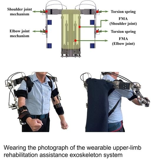
Computer-aided mechanical design of a wearable upper-limb rehabilitation assistance exoskeleton system (WURAES).
Electronics 12 00196 g001
Figure 2. Photograph of the designed WURAES.
Electronics 12 00196 g002
Figure 3. Joint structure diagram of the torsion spring module.
Electronics 12 00196 g003
Figure 4. Layout and item specifications of the designed unilateral WURAES.
Electronics 12 00196 g004
Figure 5. Coordinate system diagram of the designed WURAES.
Electronics 12 00196 g005
Figure 6. The verification process of forward and inverse kinematics.
Electronics 12 00196 g006
Figure 7. Results of kinematic validation.
Electronics 12 00196 g007
Figure 8. Unilateral arm of the designed WURAES.
Electronics 12 00196 g008
Figure 9. Dynamic model of the shoulder joint of the designed WURAES.
Electronics 12 00196 g009
Figure 10. Dynamic model of the elbow joint of the designed WURAES.
Electronics 12 00196 g010
Figure 11. Principle of the proposed proxy-based output feedback sliding mode control (POFSC) for the shoulder and elbow joints.
Electronics 12 00196 g011
Figure 12. A control block diagram of the proposed POFSC.
Electronics 12 00196 g012
Figure 13. Results of fifth-order path-tracking positioning for shoulder joint flexion angles of 30° and 45°. (a) System response, (b) tracking error, and (c) control voltage.
Electronics 12 00196 g013
Figure 14. Results of fifth-order path-tracking for elbow joint flexion angles of 60° and 75°. (a) System response, (b) tracking error, and (c) control voltage.
Electronics 12 00196 g014
Figure 15. Comparison of fifth-order path-tracking between the POFSC and PID for the shoulder joint flexion angle of 30°. (a) System response, (b) tracking error, and (c) control voltage.
Electronics 12 00196 g015
Figure 16. Comparison of fifth-order path-tracking between the POFSC and PID for the shoulder joint flexion angle of 45°. (a) System response, (b) tracking error, and (c) control voltage.
Electronics 12 00196 g016
Figure 17. Comparison of fifth-order path-tracking between the POFSC and PID for the elbow joint flexion angle of 60°. (a) System response, (b) tracking error, and (c) control voltage.
Electronics 12 00196 g017
Figure 18. Comparison of fifth-order path-tracking between the POFSC and PID for the elbow joint flexion angle of 75°. (a) System response, (b) tracking error, and (c) control voltage.
Electronics 12 00196 g018
Figure 19. Safety test and comparison of the POFSC and PID in the shoulder joint of WURAES. (a) System response, (b) tracking error, and (c) control voltage.
Electronics 12 00196 g019
Figure 20. Basic gesture settings for general users.
Electronics 12 00196 g020
Figure 21. Gesture settings for the target angle, which was selected in accordance with the user’s needs.
Electronics 12 00196 g021
Figure 22. Gesture 1 (fist) maintained for 10 s. The EMG signal and RMS graph of the eight sensors in the sEMG bracelet.
Electronics 12 00196 g022
Figure 23. Gesture 2 (spread) maintained for 10 s. The EMG signal and RMS graph of the eight sensors in the sEMG bracelet.
Electronics 12 00196 g023
Figure 24. Gesture 3 (wave-in) maintained for 10 s. The EMG signal and RMS graph of the eight sensors in the sEMG bracelet.
Electronics 12 00196 g024
Figure 25. Gesture 4 (wave-out) maintained for 10 s. The EMG signal and RMS graph of the eight sensors in the sEMG bracelet.
Electronics 12 00196 g025
Figure 26. Gesture 5 (double-tap) performed six double taps in 10 s. The EMG signal and RMS graph of the eight sensors in the sEMG bracelet.
Electronics 12 00196 g026
Figure 27. sEMG bracelet worn on the forearm to detect motion intention.
Electronics 12 00196 g027
Figure 28. Basic action experiment for elbow lifting.
Electronics 12 00196 g028
Figure 29. Basic action experiment for shoulder lifting.
Electronics 12 00196 g029
Figure 30. Basic action experiment for shoulder dropping.
Electronics 12 00196 g030
Figure 31. Basic action experiment for elbow dropping.
Electronics 12 00196 g031
Figure 32. Desired action experiment with a shoulder flexion angle of 45° and an elbow flexion angle of 60°.
Electronics 12 00196 g032
Figure 33. Desired action experiment with a shoulder flexion angle of 25° and an elbow flexion angle of 80°.
Electronics 12 00196 g033
Figure 34. Desired action experiment with a shoulder flexion angle of 5° and an elbow flexion angle of 5°.
Electronics 12 00196 g034
Table 1. Denavit–Hartenberg coordinate parameters of the designed WURAES.
Link i ϑ i / rad d i / mm i 1 / mm ε i 1 /
1 ϑ 1 0 1 0
20 d 1 2 0
3 ϑ 2 00-90
4 ϑ 3 d 2 3 90
5 ϑ 4 0 4 0
600 5 0
Table 2. Parameters used in the system model.
Parameter
F F M A Contraction force of the fluidic muscle actuator (FMA)
P i Initial pressure
Δ P Pressure change
r 1 Adjustment factor obtained after comparing the actual braided fiber length with the ideal fiber length (the smaller the fiber braiding angle or the more turns the fiber wraps around the rubber tube, the closer the parameter is to 1)
r 2 Volume ratio of the actual cylinder to an ideal cylinder (when the FMA is inflated, if the diameter of the middle part is closer to the diameter at the end, the parameter value is closer to 1, which indicates that the effect of end restriction is weaker)
ε PMA length shrinkage rate
D i Initial diameter of the FMA
ϕ i Initial fiber weaving angle
ϕ Actual fiber weaving angle
n Number of turns of the fiber winding
F A Elastic force generated by the rubber cylinder being stretched
F B Elastic force of the rubber cylinder due to its enlarged longitudinal circumference
F C Sum of the static friction between the braided fibers inside the FMA and between the rubber tube and the braided fiber layer (the static friction is affected by many factors and cannot be determined through calculations)
E T Elastic modulus of the rubber material
t r Wall thickness of the rubber tube
D r Diameter of the rubber tube after inflation and loading
D r i Initial diameter of the rubber tube
L F M A Length of the actual FMA
L m Minimum unloaded length of the FMA after inflation
Table 3. Parameters of the proposed POFSC in fifth-order path-tracking positioning control for the shoulder joint.
t e ( sec ) POFSC
Ω 1 Ω 2 Ω 3 k p k d λ n a G 0
5408016002700.451250001000
Table 4. Error in path-tracking positioning control for the shoulder joint.
Position (°)Maximum Absolute Error (°)Root-Mean-Square Deviation (°)
30°0.930.30
45°1.280.41
Table 5. Parameters of the proposed POFSC in fifth-order path-tracking positioning control for the elbow joint.
t e ( sec ) POFSC
Ω 1 Ω 2 Ω 3 k p k d λ n a G 0
542.58524009001.051250001000
Table 6. Error in path-tracking control for the elbow joint.
Position (°)Maximum Absolute Error (°)Root-Mean-Square Deviation (°)
60°1.340.52
75°0.890.44
Table 7. The controller parameters of the PID experiment.
PID
K P K i K d
0.030.50.005
Table 8. Error comparison using the POFSC and PID for the shoulder joint (30°).
Control MethodMaximum Absolute Error (°)Root-Mean-Square Deviation (°)
POFSC0.940.30
PID2.530.67
Table 9. Error comparison using the POFSC and PID for the shoulder joint (45°).
Control MethodMaximum Absolute Error (°)Root-Mean-Square Deviation (°)
POFSC1.290.41
PID5.221.84
Table 10. Error comparison using the POFSC and PID for the elbow joint (60°).
Control MethodMaximum Absolute Error (°)Root-Mean-Square Deviation (°)
POFSC1.350.52
PID3.421.49
Table 11. Error comparison using the POFSC and PID for the elbow joint (75°).
Control MethodMaximum Absolute Error (°)Root-Mean-Square Deviation (°)
POFSC0.880.44
PID4.231.92
Disclaimer/Publisher’s Note: The statements, opinions and data contained in all publications are solely those of the individual author(s) and contributor(s) and not of MDPI and/or the editor(s). MDPI and/or the editor(s) disclaim responsibility for any injury to people or property resulting from any ideas, methods, instructions or products referred to in the content.

