1. Introduction
Microwave filters are integral to wireless communication systems, allowing the desired signal to pass through while the unwanted signal is suppressed. Communication systems have to use bandpass filters to control the size of the loss, in order to transmit with the lowest possible loss, especially in RF circuits. In recent years, with the rapid development of communication technology, the use of high-frequency-band electromagnetic waves more and more frequently will inevitably lead to the increasing tension of spectrum resources and more stringent requirements for performance parameters. Coaxial-cavity bandpass filters have been widely used in communication base stations, satellite navigation, military radar and other fields, due to their low insertion-loss, high band-rejection and high selectivity [
1,
2,
3,
4,
5,
6]. In the field of RF microwaves for coaxial-cavity filters, many studies have been carried out by previous scholars, at home and abroad. The literature [
7] designed a comb coaxial cavity filter using conventional spatial coupling, but the drawback is that the in-band insertion loss is not good enough. On this basis, the introduction of dielectric coaxial cavity makes the performance of the literature [
8] improved; however, its volume still needs to be improved. A four-cavity cascaded cavity filter for the LTE band based on a stepped-impedance coaxial cavity was proposed in the literature [
9], to solve this problem. However, the development of communication technology has put new requirements on the out-of-band rejection of the filter and the filter unloaded Q. In this context, cross-coupled structures capable of generating transmission zeros out-of-band in order to be able to improve frequency selectivity have been created [
10,
11,
12] In addition, the filter size reduction is inevitably accompanied by a reduction of the cavity power capacity. Therefore, it is crucial to consider the power capacity [
13,
14,
15].
Based on the above analysis, first, by introducing a new capacitive-load coupling disc shaped like a doughnut and loaded onto the top of the metal coaxial resonator, the load capacitance is increased, and the maximum breakdown electric field of the resonator is also increased. Second, a generalized Chebyshev filter is designed and processed, and the cavity and resonator are arranged in a “triangular” fashion, to reduce the cavity size effectively. Third, the cavity-filter power capacity is analyzed at the theoretical level, and the power capacity values are calculated separately. Finally, the measured results are presented.
2. Novel Capacitive-Load Metal Resonator
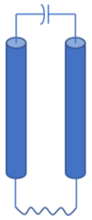
The cavity height of a single resonant cavity is generally slightly more significant than the internal coaxial-resonator height. For the traditional quarter-wavelength “water-pipe type” coaxial resonant cavity, the bottom short-circuit end is equivalent to the total inductance. In contrast, the open end of the top water-pipe conductor is equivalent to the total capacitance. However, this structure has an extended resonator height, the resonant frequency is not well tuned, and there are other problems. The equivalent model is shown in
Figure 1.
In order to solve such problems, a novel capacitive-load-coupling disc with the shape of a “doughnut” is loaded on the open end of the inner conductor. According to the parallel-plate capacitance-effect Equation (1), the size of the equivalent capacitance of the top of the resonator is proportional to the area of the disc. The larger the area, the larger the equivalent capacitance at the top:
From Equation (2), it is easy to see that the magnitude of the equivalent capacitance at the top will affect the height,
l, of the resonator:
Equation (3), which is transformed from Equation (2), clearly states that “the larger the equivalent capacitance, the smaller the height of the resonator”:
Since 0 < arctan(1/) </2, so 0 < l </4, that is, the presence of a concentrated capacitance will make the height of the resonant cavity shorter than that of a quarter-wavelength coaxial resonant cavity without the capacitance, and the larger the C, the shorter the l. Therefore, this capacitance is called “shortening capacitance”.
From
Figure 2a–c, the impact of the capacitive loading method is vividly illustrated. After loading the standard disc, the capacitive effect at the top of the resonator is enhanced, and the resonator height is reduced. After replacing the standard disc with the donut load-disc, the length in the vertical direction decreases further, which is why this paper chooses
Figure 2c. Therefore, a new capacitive-load-coupling disc with a larger area and a circular treatment is used to replace the traditional water-pipe type and standard discs. The larger disc area and the “swirl” depression of the disc-opening increases the top equivalent capacitance and shortens the resonant cavity’s length, thus achieving miniaturization.
In addition, since the resonant cavity height is closely related to the resonant frequency, the resonant frequency of the resonant cavity changes, while the equivalent capacitance changes. From
Table 1, the larger the effective contact area of the load, the lower the resonant frequency of the resonant. If the standard disc resonant in
Figure 2b is used, the single cavity size is 24 × 24 × 28.3 mm
3, and the resonant frequency is 2213.4 MHz. However, suppose the new capacitor-loaded resonant of the donut is used. In that case, the resonant rod diameter is 6 mm, the single-resonant cavity size becomes 24 × 24 × 25 mm
3, and the resonant frequency reaches 2.102 GHz. Thus, it can be seen that using the new capacitively loaded resonant not only reduces the center frequency of the resonant but also reduces the height of the resonant by 13.2%. Therefore, we can use the “donut” load resonant to miniaturize the cavity filter.
3. Design Principle of Cavity Filter
In this paper, an eighth-order two-zero-point cross-coupled coaxial cavity filter is designed using a donut capacitor-loaded metal resonator. The cavity filter is designed based on a generalized Chebyshev low-pass prototype filter, which produces an equal ripple response in the passband and has good rejection characteristics in the stopband. The design steps are divided into four main parts. First, the cavity-filter design starts with the index evaluation: Equation (4) is the filter transfer function:
In addition, the filter order is calculated by Equation (5), where
is the normalized frequency,
is the stopband rejection, and
is the in-band ripple:
Analyzing the filter topology is particularly important in the process of metrics evaluation. Different topologies correspond to completely different numbers and structures of transmission zeros, and therefore the performance of the designed filters varies greatly. According to the theoretical literature related to the design of transmission zeros for generalized Chebyshev filters [
16,
17,
18,
19,
20], two couplings with different polarities are introduced: cross-electric coupling and cross-magnetic coupling. By introducing cross-coupling, two transmission zeros outside the upper and lower passband, respectively, can be obtained, which helps to improve the out-of-band rejection. The filter topology of this design is shown in
Figure 3.
After the topology is selected, the next step is to calculate the parameters of the coupling structure by using Equation (6) to calculate the inter-cavity coupling coefficient, where
and
is the normalized low-pass prototype value and
FBW is the relative bandwidth:
Equation (7) is used to calculate the external
Q of the cavity filter, and the external
Q can be used to simulate the input–output coupling structure:
In order to make the following simulation results more accurate, the circuit design software ADS (ADS2020, Santa Rosa, CA, USA) is used to extract the required network parameters. The filter group delay can be derived as 8.14 ns, and the two transmission zeros are 2010 MHz and 2150 MHz, respectively; the coupling matrix of the filter is shown in
Figure 4.
Second, the simulation of the single-cavity and double-cavity coupling coefficients is based on the finalization of the index parameters. For single-cavity resonators, the ratio of the base half-length to the resonant rod radius is usually chosen to be between 4 and 7.2, to take into account the requirements of low loss and high power-capacity. In accordance with the above analysis, the base half-length,
p = 10 mm, and the outer rod radius,
q = 3 mm, are chosen in this paper. After determining the physical dimensions of the resonator to be 24 × 24 × 25 mm
3, the single resonant cavity was simulated in Ansys HFSS (HFSS 2021, Canonsburg, PA, USA), scanning the length of the tuning screw inserted into the cavity to determine the model to operate at the center frequency. The resonant frequency,
f, of the donut’s new capacitively loaded metal resonator is given in
Figure 5 as a function of the screw length,
t.
Third, the dual-cavity coupling coefficient simulation is determined using the “dual-mode extraction method”. The two modes are set in HFSS using the eigenmode solver, and the width of the middle air window is scanned with Equation (8), which corresponds to the coupling coefficient calculated in the index evaluation stage. For the simulation of the external
Q value, the center height of the input and output taps was simulated to correspond to the group-time-delay value of 8.14 ns:
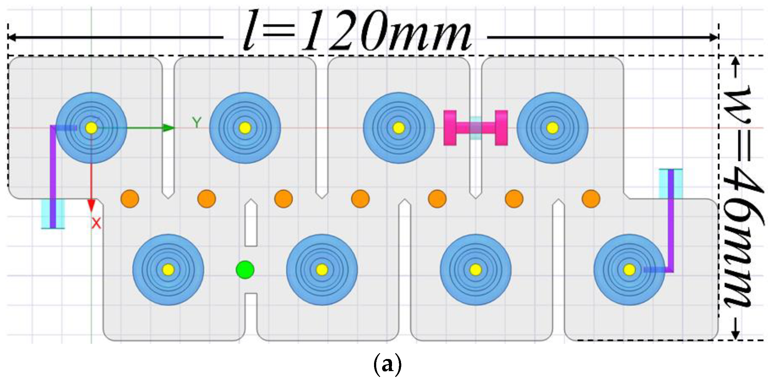
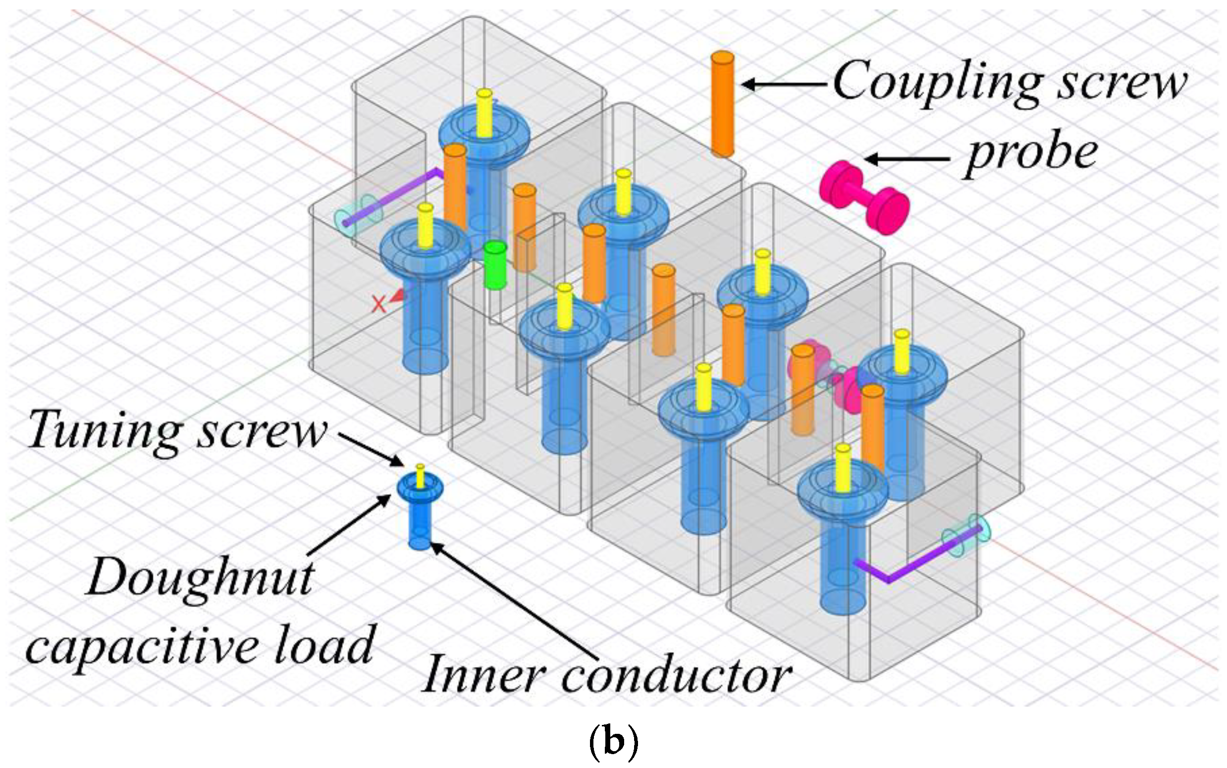
Fourth,
Figure 6 shows the overall structure of the proposed eighth-order compact cavity filter, which can effectively reduce the filter size through the cavity and resonator “Z-shaped” topology.
The direct coupling as the primary path is from 1 to 8 in sequence, while the cross-coupling as the auxiliary path is between 2 and 4 and 5 and 7.
After joint simulation and optimization using the ADS and HFSS software, the S-parameter frequency response is obtained, as shown in
Figure 7, where the return loss is ≥20 dB in the passband range of 2.04 to 2.12 GHz. Due to the introduction of two transmission zeros outside the band, the rejection characteristics are good, and possess 36 dB rejection in the stopband range, leaving the sideband of 0.02 GHz.
4. Analysis of Power and Filter Simulation Results
Different cavity structures will lead to differences in the electromagnetic field distribution. The electric field distribution of a single cavity with a fixed resonator is expressed as Equation (9):
The resonant cavity electric-energy storage is expressed as Equation (10), where Emax is the electric field amplitude at the point of maximum field strength, and
f(
x,
y,
z) is the electric field’s distribution function, characterizing the distribution’s specific situation; its modulus value is maximum 1, that is, |
f(
x,
y,
z)| = 1:
The magnitude of cavity excitation-power will change the maximum point of field strength, and the distribution function
f(
x,
y,
z) is independent of the cavity excitation-power. The total energy-storage size in a single cavity can be obtained from the above two equations, as shown in Equation (11):
After the single cavity is determined, as shown in Equation (12), if the maximum field strength is divided by the quadratic root of the total stored energy, we will find that ζ is constant, which indicates that the amplitude squared of the maximum electric field is linearly related to the total stored energy. Furthermore, Equation (13) can be used to calculate the scale factor between the cavity input-power and the maximum stored-energy:
Combining the two equations above, the relationship between the filter-port input power and breakdown field-strength can be derived as Equation (14):
If the filter is to work safely, the maximum value of the field strength in the resonator must be less than the electric-field breakdown value of the air; otherwise, the filter will be broken down. When the two are equal in magnitude, the maximum value of the cavity power-capacity can be calculated using Equation (15). The breakdown field-strength of air at regular atmospheric pressure can be taken as
Ep = 2.9 × 10
6 V/m, and the maximum energy storage of a single cavity calculated using CST Filter 3D software (CST Studio Suite 2022, Darmstadt, Germany) is 3.07173 × 10
−8 J:
The above cavity power-capacity theory [
21,
22] is integrated, and the electric field distribution of the two resonators is solved separately, based on two different resonator structures using the simulation software HFSS, while the power capacity is calculated for comparison. From the single-cavity electric-field distribution plot in
Figure 8, the maximum field strength
,
,
at a single-cavity energy storage of 1 Joule can be calculated by the intrinsic imitation of the truth, with the guarantee that the resonant frequencies are all at 2080 MHz. Therefore, in accordance with the cavity-filter-power-capacity calculation in Equation (11), the power capacity magnitudes of the three resonators can be obtained as 18.15 W, 23.52 W, and 30.5 W, respectively. This shows that the power capacity of the donut capacitor-loaded resonator increases by (30.5 − 23.52)/23.52 × 100% = 29.7%, compared with the standard-disc-loaded resonator.
5. Processing and Testing Results
A new 2080 MHz capacitively loaded bandpass filter was machined and tested, to verify the design.
Figure 9 shows a physical photo of the machined bandpass filter, and
Figure 10 measured response of a new 2080 MHz capacitively loaded cavity-filter, processed.
Figure 10 shows the measurement of the filter-scattering parameters, using a vector network analyzer, Agilent E8358A.
Considering that the loss caused by the cable between the VNA and DUT (CL bandpass filter) has some influence on the test, a two-port SOLT (short open load and straight-through) calibration was performed.
Figure 10 shows that the filter measures the passband from 2.04 GHz to 2.12 GHz, with return loss substantially better than 20 dB over almost the entire passband. In addition, an insertion loss of 0.91 dB and 0.97 dB is measured at 2010 MHz and 2150 MHz, respectively. Out-of-band rejection of 88 dB is achieved in a range only 100 MHz from the upper sideband. The agreement between the measured and simulated results is good. However, there is still some deviation during the actual measurement. Factors may cause this slight difference. For example, the SMA connector has certain losses during the assembly process, aggravating the fluctuation of in-band insertion loss. In addition, mechanical errors in milling machine processing may lead to differences in resonant cavity dimensions, thus affecting the unloaded
Q of the filter. However, in general, these errors are within the error tolerance.
To check the performance of the proposed and processed filter,
Table 2 compares it with several recent CL filters for parameters such as out-of-band rejection.
6. Conclusions
This paper proposes a novel capacitive-load cross-coupled cavity bandpass-filter with high stopband rejection, miniaturized size and higher power-capacity. The power capacity of the cavity is further enhanced by using a new resonator loaded with a donut disc to improve on the traditional plumbing-type coaxial resonator. The power capacity that the cavity can withstand is further improved by using a new resonator loaded with a donut disc, to modify the conventional water-pipe-type coaxial resonator. Then, two out-of-band transmission zeros are formed by introducing inductive–capacitive coupling, which significantly improves the signal rejection outside the filter passband. The measured total length has a center frequency of 2.08 GHz, a bandwidth of 80 MHz, a VSWR of less than 1.22, and a stopband rejection of greater than 80 dB at 2010 MHz and 2150 MHz. The measured results agree with the simulated results, verifying the feasibility and practicality of the new capacitive-load resonator miniaturization method. Overall, the filter has the advantages of miniaturization, significant stopband rejection, and good selectivity. Therefore, the proposed filter with improved performance makes it suitable for a wide range of applications, such as base stations and satellites.


