Article

Safety System Assessment Case Study of Automated Vehicle Shuttle

1
Department of Mechanical and Industrial Engineering, Tallinn University of Technology, Ehitajate tee 5, 19086 Tallinn, Estonia
2
FinEst Centre for Smart Cities, Tallinn University of Technology, Ehitajate tee 5, 19086 Tallinn, Estonia
*
Author to whom correspondence should be addressed.
Electronics 2022, 11(7), 1162; https://doi.org/10.3390/electronics11071162
Submission received: 21 February 2022 / Revised: 24 March 2022 / Accepted: 29 March 2022 / Published: 6 April 2022
(This article belongs to the Special Issue Cyber-Physical Systems in Smart Cities)

Abstract

:
Automated vehicle (AV) minibuses, i.e., AV shuttles, are gaining popularity in the testing of new types of transportation services in real traffic conditions. AV shuttles have moved from closed test areas to low-traffic public sites such as local residential areas, technology parks, university campuses, etc. These types of vehicles are usually low-speed and rely on a lidar-camera sensor set and a self-driving software stack. These new use cases are increasing these systems’ safety demands. In addition to functional safety, many other aspects need to be considered. In this study, a risk analysis model is developed, combining the fuzzy analytical hierarchy process and the Technique for Order of Preference by Similarity to Ideal Solution method. The proposed model is utilized to prioritize risks corresponding to the particular case study, based on real AV shuttle bus development, and focuses on the low-level hardware/software safety issues and improvements.

1. Introduction

Automated driving technology development is under active investigation in many different industrial sectors, such as the automotive industry, mining, machinery, etc. The automotive industry is constantly developing new autonomous driving aid system features and functionalities. The general target is to reach fully autonomous driving by the end of this decade. Many car manufacturers, such as Tesla, Ford, etc., have declared in recent years that they will reach fully autonomous driving cars very soon [1] but have had to postpone their announced deadlines many times [2]. At the same time, several IT giants are trying to develop autonomous driving, with Waymo from Google and Apple’s self-driving car project being the most well-known, but the challenges involved have been higher than initially predicted, and because of this their deadlines have been prolonged. Companies in the manufacturing industry and warehouse logistics have tested and applied automated mobile robots to make industrial processes more efficient and flexible. The Industry 4.0 and 5.0 philosophies rely heavily on connected and automated systems with seamless connectivity. Several studies have focused on the integration of AV shuttles into industrial processes as part of the Industry 4.0 concept [3]. All these efforts related to automated driving and vehicle developments face rather similar challenges. Functional safety and cybersecurity are often the main concerns when implementing and deploying automated vehicles.
Automated vehicle (AV) shuttles are a new type of transportation, targeted at solving the last-mile public transport gap. AV shuttles are mostly low-speed 6–12 seat minibuses with SAE level 4 [4] autonomy. This means that the vehicles are fully automated, without having any on-board human control devices, but are operating in a defined operational domain. The operational design domain (ODD) sets the limits in which the conditions of the vehicle are designed to operate, in terms of geographical area, weather and road conditions, speeds and traffic density, etc. Safety is the main concern and is kept in mind as the number one priority throughout the whole development process, starting from the design and development stage and ending with the deployment and services stage.
In this study, a safety assessment case study is carried out based on the AV shuttle prototype designed and developed at TalTech by the autonomous vehicles research group in cooperation with industrial partners [5,6]. The shuttle was designed modularly, and safety issues were addressed in many layers. In fact, one of the industrial partners, ABB, was responsible for designing a low-level safety system to ensure safe vehicle operation and signal-level monitoring of anomalies. Safety was included at the very beginning of the design process, and was supported by the early design methodology for the mechatronic system, proposed in the earlier collaborative work of the Aalto and TalTech research groups [7,8].
Industry 4.0 requires high levels of digitalization in order to process all the information that is generated in virtual representations or cyber versions of the physical world. The modular cyber-physical system (CPS) is a critical part of the integration between these two worlds. Modules interacting with the physical world can be divided mainly into sensors, actuators, and computational units [9]. Mobile modular CPS is typically designed as a network to create some global behavior [10], and it has significant computational resources to maintain localization, obstacle detection, safety functions, and path following. Computational resources can be divided into two categories: artificial intelligence (AI) based on high-level decision-making and lower-level control logic. AI and high-level decision-making are based on the use of special computers to run robotic operating systems (ROS). The low-level control logic is implemented near or inside the actuator or sensor modules. It handles the regulation of actuators and performs the first information processing of information received from sensors. It also controls and forwards information between the modules.
Despite intensive developments in autonomous driving, fully automated driving systems (without human supervision) are not yet allowed onto public streets together with urban traffic [11]. Safety is a key concern of any fully or partially autonomous driving system, due to the need to consider/understand several complex factors such as the environment, traffic, hardware and software systems’ reliability, information availability, cyber security, etc. For example, twelve principles have been identified by authors from different car manufacturers, which highlight the safety and security-relevant aspects [12].
The problem considered includes multiple criteria and a number of impact factors. In engineering design, evolutionary optimization techniques are most commonly utilized for handing mixed-integer variables and to provide convergence to a global optimum [13,14,15,16,17]. To reduce computing time, artificial-intelligence-based meta modeling techniques have been implemented (ANN) for the modeling of objective and constraint functions [14,15,17]. Another approach for simplifying complex engineering design problems is to decompose the initial optimization problem into simpler subproblems. In [18], a nondestructive testing method was presented for determining the elastic constants of orthotropic composites using Lamb wave propagation measurements in plates and fitting the dispersion curves by means of a simple genetic algorithm. The results obtained in [18] were extended in [19], in which the micro genetic algorithm (µGA) and two-stage Nelder–Mead simplex optimization procedure were developed. It was shown in [19] that the two-stage algorithm outperforms GA and µGA by reduced computing time. In [20], GA and a modified two-stage simplex optimization algorithm were employed to solve laminate stiffness parameter identification inverse problems. The two-stage simplex optimization algorithm appears to be less time consuming. In [21], multicriteria parametric optimization of composite sandwich plywood plates with skin layers of birch plywood and a core of straight and waved plywood cell-type ribs was performed to reduce the computing time of the the response modeling, as applied to both objective and constraint functions. The optimal design of the load-bearing capacity of high-performance concrete columns subjected to compression and flexure loads was studied in [22]. It was observed that the use of high-performance steel fiber concrete as a column material was especially effective for columns, with additional longitudinal reinforcement, and the load-bearing capacity was up to 15%.
However, the problem considered in the current study has some specific features. The evaluations (judgments) provided by decision makers include uncertainty. The evolutionary multicriteria optimization methods described in the previous section have been applied with success in solving a wide class of engineering design problems [13,14,15,16,17,18,19,20,21,22]. However, despite their stochastic nature, these evolutionary algorithms are not well suited for handling judgements involving uncertainty. For this reason, in the following, multicriteria decision-making (MCDM) methods are utilized.
Firstly, for the prioritization of the criteria, the fuzzy analytic hierarchy process (FAHP) is applied. The Fuzzy AHP was introduced as a combination of fuzzy sets and AHP [23]. The FAHP has an obvious advantage over AHP; it simplifies decision makers’ evaluations by replacing fixed-value judgments with interval judgments.
Secondly, for the prioritization of risks, the Technique for Order of Preference by Similarity to Ideal Solution (TOPSIS) is applied. According to TOPSIS, the most preferred alternatives should have the shortest distance from the positive ideal solution (PIS) and the farthest distance from the negative ideal solution (NIS) [24]. The TOPSIS method has found wide use in transportation and intelligent vehicle systems [11,25,26]. In [26], a hybrid approach was employed, combining the TOPSIS and AHP methods.
Other popular MCDM methods include Elimination and Choice Translating Reality (ELECTRE), Vlsekriterijumska optimizacija IKompromisno Resenje (VIKOR), Preference-Ranking Organization Method for Enrichment Evaluations (PROMETHEE), the weighted sum model (WSM) and weighted product model, etc. The ELECTRE method is used to develop a solution based on an outranking relationship between two alternatives [27]. The implementation of the ELECTRE algorithms is estimated to be rather complex. The VIKOR method determines the optimal solution based on estimating the closeness of alternatives to an ideal alternative [27]. This method may become challenging in the case of conflicting scenarios. The PROMETHEE method belongs to the class of outranking methods and it is based on the comparison of the amplitude of the deviations between the evaluations of the alternatives within each criterion [27]. In the case of this method, an extra tool is needed for the evaluation of the weights of the criteria. According to the weighted sum model (WSM) the optimal solution is determined as the one with the best value of the weighted sum. In the case of the weighted product model (WPM) the summation is replaced by multiplication [27].
The reasons for the selection of the TOPSIS method the current study can be outlined as follows.
  • TOPSIS is simple to implement;
  • TOPSIS provide robust solutions, it tends to provide a positive ideal solution, but avoid a negative ideal solution; and
  • TOPSIS has been utilized with success in the study of intelligent vehicle systems.
In the following, the fuzzy AHP and TOPSIS approaches are combined for the prioritization of the criteria and risks, respectively. The proposed fuzzy sets-based approach allows us to apply linguistic assessments corresponding to the natural representation of the judgment [23,24].
This paper focuses on providing a practical approach to the implementation of a cyber-physical system on autonomous vehicles, focusing on the AV shuttle in particular. The safety issues are studied in the context of considered problems. The risks and their evaluation criteria are developed for a particular class of problems.

2. Background of Key Automotive Standards

Technological innovations and progress in the automotive industry, especially with the introduction of driver-assist and automated driving systems, have brought about a need for standards that define functional safety and functions that contribute to the prevention of accidents in emergency situations. Functional safety is a method of reducing risks to an acceptable level to ensure safety by devising functions. Among many other standards, not limited to the automotive field, ISO 26262 is a functional de facto safety standard for electrical and electronic systems in road vehicles, based on IEC 61508. ISO 26262—A, B, C, and D define ASIL as a risk classification system. A represents the lowest degree, and D represents the highest degree of automotive hazard. It is mainly used as a basis to perform hazard analysis and risk assessment for vehicle electronic control units (ECUs). It is possible to measure severity, exposure, and controllability and provide classifications. Each classification is broken down into sub-classes. These classifications and sub-classes are analyzed and combined to determine the required ASIL [28,29].
Manufacturers must meet a list of specific industry standards throughout the component manufacturing and testing process in order for the automotive to qualify. The IATF 16949/ISO 9001 international standard defines the requirements for a quality management system for organizations in the automotive industry, including automotive production, service, and accessory parts organizations [30].
The durability standards of automotive electronic components are defined by the component type. AEC-Q100 is a failure mechanism-based stress test qualification for packaged integrated circuits. An AEC-Q100-qualified device means that the device has passed the specified stress tests and guarantees a certain level of quality/reliability [31]. AEC-Q200 is a global stress resistance standard set for all passive electronic components. Five temperature ranges are defined. Parts are deemed to be AEC-Q200-qualified if they have passed the stringent suite of stress tests [32]. SAE USCAR2 is a standard that covers the performance testing of road vehicle electrical terminals and connectors [33].

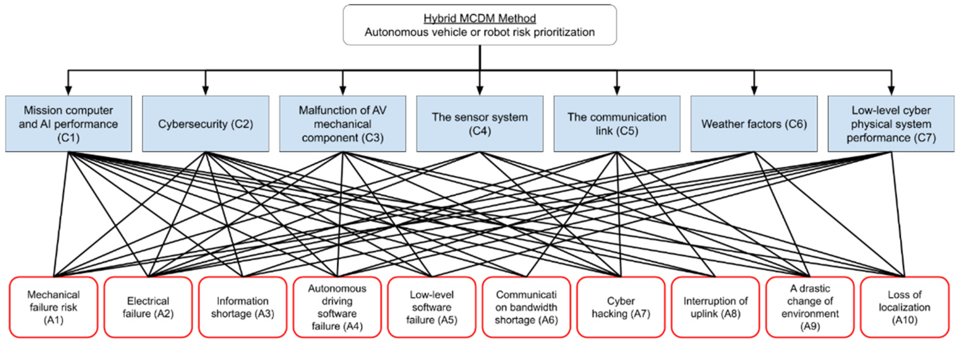
3. Risk Evaluation Model Development

Safety is one of the most critical issues in the development of mobile robots and self-driving vehicles, since a high price can be paid for shortcomings in this area, depending on the safety topics involved. The risk analysis presented here provides an overview of the current situation and forms a basis for safety improvements in future solutions. The proposed risk evaluation model includes three main modules:
  • Formulation of criteria and risks [34];
  • Prioritization of criteria (fuzzy AHP);
  • Prioritization of risks (fuzzy TOPSIS).
The first module covers the formulation of the criteria and risks for considered mobile robot types. It was introduced by authors in [34] and is described as follows.
Mission computer and AI performance (C1): This criterion refers to the reliability of the mission computer and AI system. Situations in which the AV vehicle is unable to perform the tasks assigned to it may lead to the cessation of production or interruption of the transportation of passengers and goods.
Cybersecurity (C2): This criterion refers to all sorts of hacking of automated systems. Remote-control attacks are one of the prioritized security threats. Autonomous passenger transport carries the risk of the passenger gaining access to the vehicle’s internal network or computer viruses finding their way into the system.
Malfunction of AV mechanical component (C3): The mechanical components of an autonomous vehicle may fail, which creates the risk of accidents and further damage.
The sensor system (C4): This criterion refers to the reliability of the sensors. The sensors may stop working due to mechanical breakdown or electrical failure. The operation of the sensors can maliciously interfere with lasers, radio jammers, and other devices.
The communication link (C5): This criterion refers to the reliability of the communication links. The components of the communication link may fail due to hardware or software issues and hacking. A loss of communication may lead to accidents.
Weather factors (C6): This criterion refers to the driving environment factors, including weather conditions and other factors that are essential for prioritizing the risk in a driverless vehicle.
Low-level cyber-physical system performance (C7): This criterion refers to low-level cyber-physical system performance and failure, which also creates the risk of accidents and further damage.
Mechanical failure risk (A1): This risk category refers to the failure of the mechanical components due to normal wear and tear, manufacturing or design errors, corrosion, vandalism, mishandling, or an accident.
Electrical failure (A2): This risk category refers to the failure of the electrical components. Electrical components can be divided roughly into ECUs, wiring harness, batteries, sensors, and mechanical actuators. Failure may occur due to manufacturing or design errors, corrosion, short circuit, overheating, software failure, or hacking. Mechanical damage is also possible. These types of faults can lead to greater damage, such as fire or accident.
Information shortage (A3): This risk category refers to the failure relating to the loss of communication. As the vehicle or robot should operate autonomously, this type of error does not directly cause major damage. However, if an attempt is made to stop or drive the vehicle due to a previous malfunction, an information shortage may result in an accident.
Autonomous driving software failure (A4): This risk category refers to the failure of autonomous driving software. This is one of the most prioritized security threats, which could lead to an accident. This type of failure is difficult to detect and correct from the lower side and requires urgent intervention by the remote-control center.
Low-level software failure (A5): This risk category refers to a low-level software failure, mainly due to programming or design errors. This risk is controllable by making the right design choices in the cyber-physical architecture. However, the occurrence of these failures is dangerous, as the actuators can move unpredictably, and the vehicle may undergo high acceleration, causing a crash. The actuators and the electrical system may be damaged due to overload or due to signals occurs in the wrong order.
Communication bandwidth shortage (A6): As the vehicle should operate autonomously, this type of error does not directly cause major damage. However, if an attempt is made to stop or drive the vehicle due to a previous malfunction, a communication bandwidth shortage may result in an accident. This risk category refers to the fact that the remote-control center may lose access to the vehicle overview information and the remote-control option.
Cyber-hacking (A7): This risk category is involved with the deliberate exploitation of automated vehicle systems by unauthorized entities. The target of the attack can vary, ranging from an attack on software to managing the system. Remote-control attacks are one of the highly prioritized security threats, and could be considered the most dangerous type of attack.
Interruption of uplink (A8): As the vehicle should operate autonomously, this type of error does not directly cause major damage, but the remote-control center may lose access to the vehicle overview information and the remote-control option.
A drastic change of environment (A9): A drastic change in the environment may pose a risk. For example, snow may accumulate on the sensor’s surfaces, and heavy rain or snowing may disturb the operation of the sensors. An inside environment may contain dust, food, and other substances which may cover sensors or block mechanical actuators. An accident may occur if dire circumstances coincide. A significant drop in temperature may cause an electrical system failure.
Loss of localization (A10): In this case, the vehicle does not know where it is located. An accident may occur if the vehicle tries to move. With appropriate design choices for autonomous driving software, this risk should be minimized. In addition, if the vehicle is unable to restore its localization, the remote-control center should take control.
Based on the above-defined criteria and risks, a decision hierarchy tree for the considered mobile autonomous systems can be established, as shown in Figure 1.
In the following section, the last two modules of the risk evaluation model are described.

3.1. Criteria Prioritization Using Fuzzy AHP

In the following, the fuzzy AHP approach, based on triangular fuzzy numbers (TFN), is applied to prioritize the criteria introduced above.
Step 1. The criteria were evaluated in terms of linguistic variables. First, the linguistic variables were introduced, as shown in Table 1, to simplify the evaluation process of the importance of criteria [35].
Next, the expert group of decision-makers filled the pairwise comparison matrix criteria vs. criteria in terms of linguistic variables. Table 2 presents the linguistic “grades” given by one expert as an example.
Step 2. The linguistic scales were transferred to triangular fuzzy numbers (TFN) based on Table 1. These individual tables are omitted herein for the sake of brevity.
Step 3. The aggregated evaluation matrix, presented in Table 3, was computed by applying a fuzzy geometric mean
r i j = ( n = 1 N c i j n ) 1 / N .
In Equation (1), c i j n stands for the fuzzy comparison value in terms of the TFN of criteria i to criteria j given by the n -th expert and N is the total number of decision-makers involved. The computed values of the pairwise comparison matrix r i j are given in Table 3. Here r i j = ( l i j , m i j , u i j ) are triangular Fuzzy numbers, where l ,   m , and u stand for lower, medium, and upper values, respectively.
Step 4. Next, the aggregation was applied with respect to each row of the aggregated comparison matrix given in Table 3. As a result, the fuzzy comparison values r i = ( l i , m i , u i ) can be evaluated as:
r i = ( j = 1 N c r i t r i j ) 1 / N c r i t .
In Equation (2) N c r i t stands for the number of criteria used.
Step 5. The triangular fuzzy weight w i of criteria i is determined as the normalized value of the r i .
w i = ( l i , m i , u i ) = r i ( r 1 r 2 r N c r i t ) 1 , i = 1 , , N c r i t .
Step 6. Finally, the crisp weights can be obtained by applying defuzzification for fuzzy weights as (different approaches for defuzzification can be found in [36]).
w i C r i s p = l i + [ ( u i l i ) + ( m i l i ) ] / 3 .
In Table 4 are presented the fuzzy and crisp weights, as well as the final ranks of the criteria.
Step 7. The criteria were prioritized based on normalized crisp weights given in column 5 of Table 4. The consistency ratio (CR) of the defuzzified matrix was calculated and validated (should be <0.1).
The normalized crisp weights and ranks of criteria can be considered as final results of the fuzzy AHP implemented above.

3.2. Risk Prioritization Using Fuzzy TOPSIS

In the following, the risk evaluation was performed by taking into account the results of the applied fuzzy AHP and utilizing the fuzzy TOPSIS approach.
Step 1. The pairwise comparison risk vs. criteria analysis was performed by the same expert group who performed the evaluation of the criteria. Similarly to above, the triangular fuzzy numbers and the linguistic variables were employed [37]. The linguistic variables for the evaluation of the importance of the risks with respect to criteria are presented in Table 5.
Step 2. The risk evaluation with respect to criteria was performed. The sample results of one decision-maker are shown in Table 6.
Step 3. The linguistic “grades” given by decision-makers (see Table 6) were transferred to triangular fuzzy numbers (TFN) based on the relations given in Table 5.
The aggregation of the decision-makers’ evaluation matrices was performed by applying the fuzzy arithmetic mean (in the case of Fuzzy AHP was applied geometric mean) as:
x i j = 1 N n = 1 N x i j n ,
where N   is the number of decision-makers and x i j n stands for the rating of risk i to criterion j given by the n -th decision-maker. The computed fuzzy triangular numbers x i j = ( l i j , m i j , u i j ) are presented in Table 7.
Step 4. The aggregated fuzzy decision matrix was normalized. The fuzzy weights of the criteria obtained by applying fuzzy AHP (see Table 4) were utilized to compute the weighted normalized decision matrix given in Table 8.
Step 5. The distances of each risk to positive and negative ideal solutions were computed as
d i + = j = 1 n d ( v i j , v j + ) ,   i = 1 , , m ,   d i = j = 1 n d ( v i j , v j ) ,   i = 1 , , m ,
where
v j + = ( 1 , 1 , 1 ) ,   v j = ( 0 , 0 , 0 ) ,   j = 1 , 2 , , n
and
d ( x , y ) = ( 1 3 ) . [ ( l x l y ) 2 + ( m x m y ) 2 + ( u x u y ) 2 ] .
Step 6. Based on the positive and negative ideal solution, the similarities were calculated as
C i = d i d i + + d i ,   i = 1 , , m .
The risks were ranked based on the values of the similarities. Table 9 presents the positive and negative ideal solutions, the similarities, and the final ranking of the risks.
The estimation of a number of different types of risks and the evaluation of multiple criteria is a challenging task in the development of AV systems. The fuzzy AHP-TOPSIS-based risk analysis approach proposed here provides estimates of the ranks of criteria and risks. Cyber hacking, low-level software failure, and electrical failure appear to be the most critical risks in the current case study. The weights of criteria and similarity values of the risks are another valuable piece of information for the further improvement of AV systems.
As the results point out, low-level software failures are one of the highest risk factors and thus require a high level of attention during the system design stage and implementation stage. The following case study covers low-level system safety improvements for the TalTech iseAuto AV shuttle, which was designed and manufactured for research and educational purposes by the Autonomous Vehicles lab at Tallinn University of Technology.

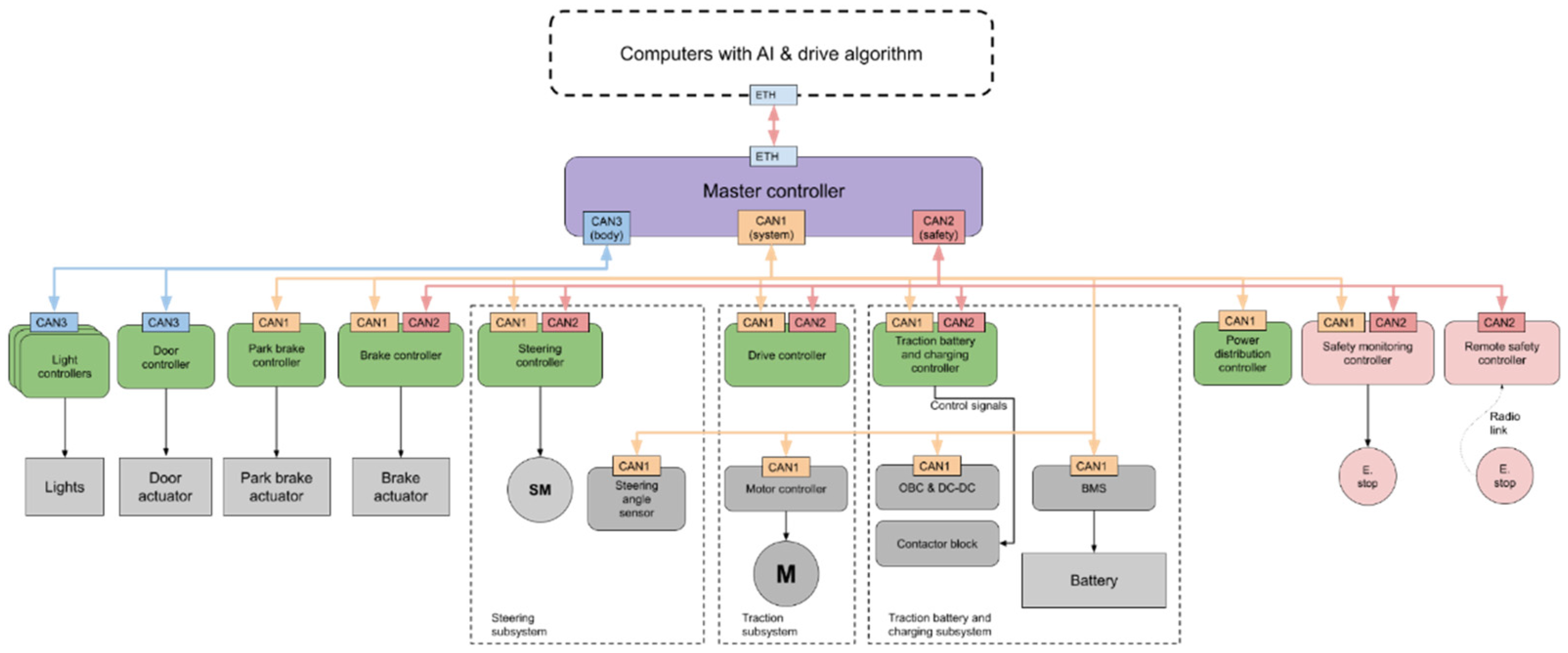
4. Low-Level Communication and Safety Architecture for the AV Shuttle Based on the Risk Evaluation Model

The iseAuto AV shuttle was designed to be a minibus, with the aim of operating primarily on the territory of the university campus. Therefore, the speed of the minibus was limited to 20 km/h. The architecture of the vehicle CPS was first explained in [34], and it is divided into layers as described in Figure 2. The AI and high-level decision-making layer make autonomous driving decisions based on the sensor’s input layer. The various controlling commands are sent to the actuator layer, which has a mission-critical functionality to take care of the robot’s actual control.
The shuttle’s control logic is divided into two layers—the master controller layer and the function-based controller layer. The main task of the master controller is to act as a central gateway between all the nodes. Function-based controllers are classified as critical or non-critical. Critical controllers are involved in the direct control of the vehicle or the control of the traction battery and its charging. For safety reasons, separate safety controllers have been added to stop the vehicle when a fault is detected. The communication is shared between three CAN buses:
  • CAN 1 for all system controllers;
  • CAN 2 for safety-related controllers and for duplicating critical system messages; and
  • CAN 3 for vehicle body-related and other low-priority controllers.
The correct design of critical CAN networks is important. First, is it essential to choose the correct package IDs for CAN bus data frames. The data frames have an ID that can be used to separate data frames, and data frames are ranked in order of importance using this ID. Data frames with a lower ID are preferred [38]. An extra checksum and counter value can be added into critical data frames. The controller using the data frames will only do so if the checksum is correct. A possible reason for this is hacking because the CAN network is not encrypted. A 15-bit CRC checksum is added to every CAN message via a hardware layer anyway, but it is harder to inject the messages into the network if there is an extra checksum. Counter values are used to check if some data frame loss has occurred. For faster system diagnostics and error detection, a diagnostic data frame should be sent out by the ECU. For example, if the expected data frame does not arrive at the correct time interval, if the supply voltage limit is exceeded, or something else happens, the flag is set. Every diagnostic data frame on the CAN bus can carry 8 bytes of data or 64 flags. The safety controller monitors these flags and can decide to trigger a safety logic process. A similar logic is used in Tesla vehicles [39].
ECU components should comply with international automotive application standards. The previously used STM32 family microcontroller is not certified for automotive use. A good replacement for the STM32 is the general-purpose STMicroelectronics SPC5 family automotive microcontrollers, which qualify according to the AEC-Q100 standard and have a wide range of automotive interfaces. The chosen specialized hardware should allow the achievement of safety goals [40]. Passive components qualifying to AEC-Q200 and automotive connectors are used in the design of new ECUs. Automotive connectors should be crimp-type connectors in order to establish better connections and save time. For example, the WireLock low-mating-force automotive-grade connector system is a good option and is USCAR-2 V2-compatible.
It is good practice to design the ECU internal electronics as a fortress. This means that over- or undervoltages (provided that they remain within the selected limits), electrical noise, and short circuits applied to power inputs, digital IO, or data interfaces, cannot interrupt the operation of the microcontroller. If the ECU has a power source for the sensors, and if this source is shorted or something draws too much current, microcontroller power should not be affected. Any such errors should be logged, and flags should be set and sent out by the diagnostic data frame on the CAN bus.
Authentication and secret key establishment, providing confidentiality and integrity to the in-vehicle network, makes it possible to design a process that does not violate the real-time constraints of automotive CPS applications even in the presence of errors in computation and transmission [41]. Furthermore, it is possible to integrate both security and dependability principles simultaneously in the design of ECUs with a negligible performance, energy, and resource overhead [42]. The ISO 26262 standard requires that at least one critical fault must be tolerated by the automotive applications to maintain intended functionality or achieve or maintain a safe state [28], and the ASIL, risk classification system, must be used to mitigate the risks when designing every ECU.
The power system can be built using regular automotive fuses. Today’s state-of-the-art cars use electronic protection circuits for replacing fuse and relay boxes [43]. Electronic protection circuits are not only faster but also allow faults to be logged as soon as they occur. In addition to feeding the critical controllers, two separately protected supply lines can be added. For example, the steering controller, when power electronics and their controlling circuits are duplicated, is a good candidate. In this case, if one power line is faulty or short-circuited, the other will continue to work.
If something unexpected happens, then the safety logic is triggered, as shown in Figure 3. It is divided into three stages:
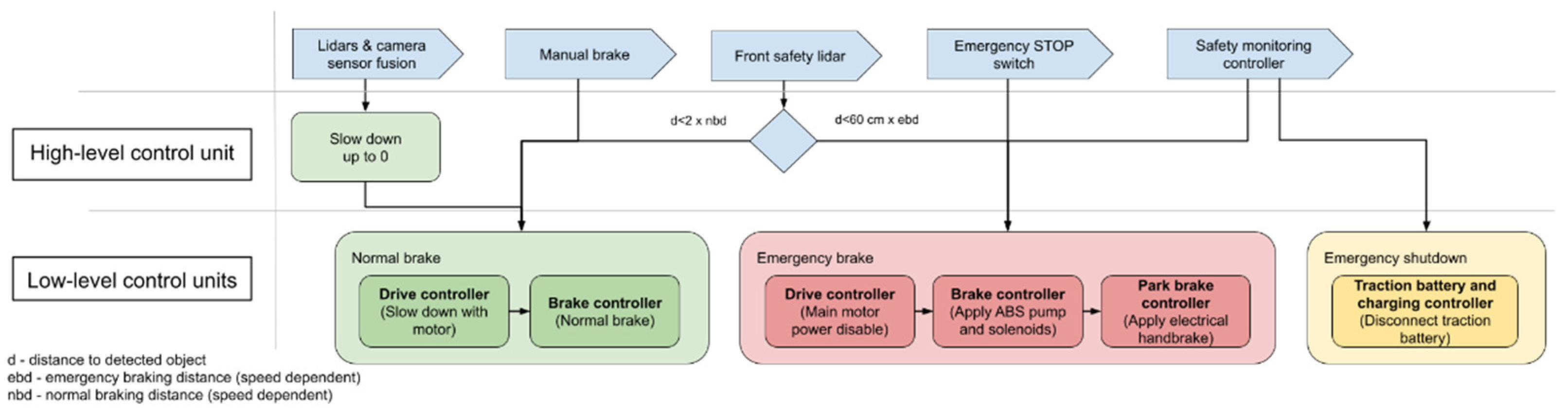
  • Normal braking is usually triggered by a high-level computer or safety lidar. When there is free room regenerative braking can be used, followed by normal braking if needed;
  • The emergency brake is triggered when the emergency STOP switch is pressed, the front safety lidar sees something that is too close, or when the safety monitoring controller is triggered by some fatal error;
  • An emergency shutdown may be followed by emergency braking when the emergency STOP switch is pressed (for example, a risk of fire because there is smoke in the cabin), the crash detection system is triggered, or some serious error is detected. Emergency shutdown disables the high-voltage traction battery.
Normal and emergency braking is based on brake-by-wire (BBW) technology, which should cooperate with the regenerative braking system controlled by the drive controller ECU. The hydraulic brake system is made controllable by replacing the master cylinder with a gear pump. The intensity of the braking depends on the pressure of the brake fluid. The speed of the pump is controlled according to the feedback from the brake fluid pressure sensor and the required braking force sent by a high-level control system. The valve must be opened to release the brake. One of the biggest disadvantages of this system is that it is difficult to release the brake precisely and smoothly. The solution is to develop a distributed brake-by-wire system, as proposed in [44], which has a hydraulic actuator for every wheel. This provides flexible and precise braking force control with shorter or no brake pipes. A disadvantage of this system is the lack of freely available brake components. Bosch developed a brake booster system called iBooster, which is used in Tesla and other cars capable of automatic driving. The brake pressurization rate of the iBooster is three times that of the conventional braking system, and it was meant to replace vacuum brake boosters [45]. Bosch iBooster is available as a spare part, but further research and testing are required to control it over the CAN bus. iBooster is compatible with the classic hydraulic braking system. In addition to normal brakes, a parking brake is also available in the iseAuto AV shuttle, controlled by an electric drive. This is intended primarily to prevent the vehicle from moving on its own but can be used in an emergency when the main brake is not working.
Self-driving vehicles do not have a driver who can detect problems directly. One of the most likely problems is a low tire pressure or flat tire. Tire pressure plays an important role in safety and energy consumption. If the AI and high-level decision-making layer of the self-driving vehicle are not alerted to this issue, a dangerous situation can arise. Today’s vehicles use a tire-pressure monitoring system (TPMS). The TPMS measures the air pressure inside the pneumatic tires. Inside the stem of every wheel, an electronic unit is located that contains a pressure sensor, microcontroller, radio link, and battery. The TPMS control ECU has a radio receiver that reads pressure information. Methods to implement TPMS systems have been described [46], but in most cases, such systems are intended to warn the driver. The new iseAuto AV shuttle should be equipped with some sort of TPMS system to make it more secure. As a further development of the TPMS, it is possible to measure dangerous impacts on tires (to measure pressure pikes) when a vehicle accidentally drives against a road curb or against some objects on the road. If TPMS is triggered, the vehicle should probably park safely so as not to obstruct traffic and to call for help.

5. Conclusions

The final results of the study can be outlined as follows.
  • An MCDM risk evaluation model was developed for safety system assessment;
  • A list of prioritized risks was developed, as presented in Table 9;
  • The most critical risks were determined to be cyber hacking, low-level software failure, and electrical failure.
First, the criteria and risks were defined in a previous study by the authors. Drawing on the results of that study, the seven criteria and ten risks were formulated and described.
Next, the criteria were prioritized by applying the fuzzy analytical hierarchy process. As a result, the sensor system (reliability of the sensors), the performance of low-level cyber-physical systems, and the malfunctioning of AV mechanical components were identified as the most important criteria for decision-making.
Finally, the risks were prioritized by utilizing the Technique for Order of Preference by Similarity to Ideal Solution method. As a result, cyber hacking, low-level software failure, and electrical failure were found to be the most critical risks for the current case study.
Based on the analysis of the highest risk affecting full system safety, low-level system safety criteria were selected in this research as an improvement option. The main ideas for testing of the improved solution for the low-level system architecture were proposed and briefly analyzed in the context of a particular AV shuttle—the TalTech iseAuto.
The information provided on the ranking of the criteria and risks consists only of positions, as a rule, without providing detailed information on how far are values from each other, etc. The crisp weights of the criteria and the similarity values of the risks provide more detailed and valuable information for the further improvement of mobile robot systems.
The approach proposed here may be used to simplify decision-maker’s judgments and to handle uncertainty caused by these judgments. The risks identified here are rather universal, applicable not only to a specific autonomous shuttle design, but also to similar outdoor mobile robots and other low-speed automated vehicles. The risk evaluation results can provide an input for further developments and improvements of AVs and, in particular, for the TalTech iseAuto version 2, which is under development.

Author Contributions

Conceptualization, H.P. and J.M.; methodology, H.P. and J.M.; model development, J.M.; validation, R.S. and K.K.; formal analysis, H.P.; investigation, H.P.; resources, R.S.; data curation, J.M.; writing—original draft preparation, H.P.; writing—review and editing, H.P., J.M., K.K. and R.S.; visualization, H.P.; supervision, R.S.; project administration, R.S.; funding acquisition, R.S. All authors have read and agreed to the published version of the manuscript.

Funding

This work was supported via funding by two grants: the European Union’s Horizon 2020 Research and Innovation Programme grant agreement No. 856602, and the European Regional Development Fund, co-funded by the Estonian Ministry of Education and Research, grant No. 2014-2020.4.01.20-0289.

Institutional Review Board Statement

Not applicable.

Informed Consent Statement

Not applicable.

Data Availability Statement

Not applicable.

Acknowledgments

The financial support from the Estonian Ministry of Education and Research and the Horizon 2020 Research and Innovation Programme is gratefully acknowledged.

Conflicts of Interest

The authors declare no conflict of interest. The funders had no role in the design of the study; in the collection, analyses, or interpretation of data; in the writing of the manuscript, or in the decision to publish the results.

References

  1. Della Cava, M. Tesla Announces Fully Self-Driving Cars. USA Today, 2016. Available online: https://eu.usatoday.com/story/tech/news/2016/10/19/tesla-announces-fully-self-driving-fleet/92430638/ (accessed on 13 March 2022).
  2. Korosec, K. Ford Postpones Autonomous Vehicle Service until 2022. TechCrunch, 28 April 2020. Available online: https://techcrunch.com/2020/04/28/ford-postpones-autonomous-vehicle-service-until-2022/?guccounter=1&guce_referrer=aHR0cHM6Ly93d3cuZ29vZ2xlLmNvbS8&guce_referrer_sig=AQAAADBFTUMYSsgWbXuqaxjPCxHsMVa-3xDxahKGV33qvhPjg0sPUdDXuypt_zViyxxg-nZe8HSlMZWfgvGWu9ch1uB0Sa4fnxRslcxGyh5xfICKKji9dPOz4JLHXH9U-QLnno5a3WN5YnJ9F9o4qt-7C76fa9ULO6mkuCGMXLNRns2x (accessed on 21 December 2021).
  3. Sell, R.; Rassolkin, A.; Wang, R.; Otto, T. Integration of Autonomous Vehicles and Industry 4.0. Proc. Eston. Acad. Sci. 2019, 68, 389. [Google Scholar] [CrossRef]
  4. Shuttleworth, J. SAE Standard News: J3016 Automated-Driving Graphic Update, 2019. Available online: https://www.sae.org/news/2019/01/sae-updates-j3016-automated-driving-graphic (accessed on 20 December 2021).
  5. Sell, R.; Leier, M.; Rassõlkin, A.; Ernits, J. Self-Driving Car ISEAUTO for Research and Education. In Proceedings of the 2018 19th International Conference on Research and Education in Mechatronics (REM), Delft, The Netherlands, 7–8 June 2018; pp. 111–116. [Google Scholar] [CrossRef]
  6. Rassõlkin, A.; Sell, R.; Leier, M. Development Case Study of the First Estonian Self-Driving Car, Iseauto. Electr. Control Commun. Eng. 2018, 14, 81–88. [Google Scholar] [CrossRef] [Green Version]
  7. Sell, R.; Coatanéa, E.; Christophe, F. Important Aspects of Early Design in Mechatronic. In Proceedings of the 6th International DAAAM Baltic Conference, Tallinn, Estonia, 24–26 April 2008. [Google Scholar]
  8. Sell, R.; Petritsenko, A. Early Design and Simulation Toolkit for Mobile Robot Platforms. Int. J. Prod. Dev. 2013, 18, 168. [Google Scholar] [CrossRef]
  9. Mahmood, K.; Karjust, K.; Raamets, T. Production Intralogistics Automation Based on 3D Simulation Analysis. J. Mach. Eng. 2021, 21, 101–115. [Google Scholar] [CrossRef]
  10. Pikner, H.; Karjust, K. Multi-Layer Cyber-Physical Low-Level Control Solution for Mobile Robots. IOP Conf. Ser. Mater. Sci. Eng. 2021, 1140, 012048. [Google Scholar] [CrossRef]
  11. Ziyan, C.; Shiguo, L. China’s Self-Driving Car Legislation Study. Comput. Law Secur. Rev. 2021, 41, 105555. [Google Scholar] [CrossRef]
  12. Safety First for Automated Driving. Available online: https://newsroom.intel.com/wp-content/uploads/sites/11/2019/07/Intel-Safety-First-for-Automated-Driving.pdf (accessed on 24 December 2021).
  13. Yue, H.; Medromi, H.; Ding, H.; Bassir, D. A novel hybrid drone for multi-propose aerial transportation and its conceptual optimization based on surrogate approach. J. Phys. Conf. Ser. 2021, 1972, 12103. [Google Scholar] [CrossRef]
  14. Guessasma, S.; Bassir, D. Neural network computation for the evaluation of process rendering: Application to thermally sprayed coatings. Int. J. Simul. Multisci. Des. Optim. 2017, 8, A1. [Google Scholar] [CrossRef] [Green Version]
  15. Tang, X.G.; Rezoug, M.; Hamzaoui, R.; Bassir, D.; El Meouche, R.; Hreim, J.F.; Feng, Z.Q. Multiobjective optimization on urban flooding using RSM and GA. Adv. Mater. Res. Adv. Civ. Eng. 2011, 255–260, 1627–1631. [Google Scholar] [CrossRef]
  16. Guessasma, S.; Bassir, D. Comparing heuristic and deterministic approaches to optimize mechanical parameters of biopolymer composite materials. Mech. Adv. Mater. Struct. 2009, 16, 293–299. [Google Scholar] [CrossRef]
  17. Herranen, H.; Majak, J.; Tsukrejev, P.; Karjust, K.; Märtens, O. Design and Manufacturing of composite laminates with structural health monitoring capabilities. Procedia CIRP 2018, 72, 647–652. [Google Scholar] [CrossRef]
  18. Lasn, K.; Klauson, A.; Chati, F.; Décultot, D. Experimental determination of elastic constants of an orthotropic composite plate by using Lamb waves. Mech. Compos. Mater. 2011, 47, 435–446. [Google Scholar] [CrossRef]
  19. Lasn, K.; Klauson, A. Non-destructive identification of elastic constants by vibration measurements and optimization. In Proceedings of the OAS 2011: International Conference on Optimization and Analysis of Structures, Tartu, Estonia, 25–27 August 2011. [Google Scholar]
  20. Lasn, K.; Echtermeyer, A.T.; Klauson, A.; Chati, F.; Décultot, D. Comparison of laminate stiffness as measured by three experimental methods. Polym. Test. 2015, 44, 143–152. [Google Scholar] [CrossRef]
  21. Frolovs, G.; Rocens, K.; Sliseris, J. Optimal design of plates with cell type hollow core. IOP Conf. Ser. Mater. Sci. Eng. 2017, 251, 12075. [Google Scholar] [CrossRef]
  22. Sliseris, J.; Buka-Vaivade, K. Numerical Modelling of High Strength Fibre-Concrete’s columns in Multi-Storey Building. IOP Conf. Ser. Mater. Sci. Eng. 2019, 660, 012062. [Google Scholar] [CrossRef]
  23. Vinodh, S.; Prasanna, M.; Hari Prakash, N. Integrated Fuzzy AHP-TOPSIS for selecting the best plastic recycling method: A case study. Appl. Math. Model. 2014, 38, 4662–4672. [Google Scholar] [CrossRef]
  24. Bakioglu, G.; Atahan, A.O. AHP integrated TOPSIS and VIKOR methods with Pythagorean fuzzy sets to prioritize risks in self-driving vehicles. Appl. Soft Comput. 2020, 99, 106948. [Google Scholar] [CrossRef]
  25. Harrison, M.; Yang, Z.; Nguyen, T.T.; Kavakeb, S.; Wang, J.; Bonsall, S. A TOPSIS method for vehicle route selection in seaports—A real case analysis of a container terminal in North West Europe. In Proceedings of the 2015 International Conference on Transportation Information and Safety (ICTIS), Wuhan, China, 25–28 June 2015; pp. 599–606. [Google Scholar] [CrossRef]
  26. Pachêco Gomes, I.; Renan Bruno, D.; Santos Osório, F.; Fernando Wolf, D. Diagnostic Analysis for an Autonomous Truck Using Multiple Attribute Decision Making. In Proceedings of the 2018 Latin American Robotic Symposium, 2018 Brazilian Symposium on Robotics (SBR) and 2018 Workshop on Robotics in Education (WRE), Pessoa, Brazil, 6–10 November 2018; pp. 283–290. [Google Scholar] [CrossRef]
  27. Emovon, I.; Oghenenyerovwho, O.S. Application of MCDM method in material selection for optimal design: A review. Results Mater. 2020, 7, 100115. [Google Scholar] [CrossRef]
  28. Debouk, R. Overview of the 2nd Edition of ISO 26262: Functional Safety-Road Vehicles; General Motors Company: Warren, MI, USA, 2018. [Google Scholar] [CrossRef]
  29. ISO 26262; Road Vehicles—Functional Safety—Part 2: Management of Functional Safety. International Organization for Standardization: Geneva, Switzerland, 2018.
  30. IATF 16949; Quality Management System Requirements for Automotive Production and Relevant Service Parts Organisations. Automotive Industry Action Group: Southfield, MI, USA, 2016; ISBN 9781605343471.
  31. Automotive Electronics Council. Failure Mechanism Based Stress Test Qualification for Integrated Circuits; AEC Q100 Rev. H; Automotive Electronics Council: Luton, UK, 2014. [Google Scholar]
  32. Automotive Electronics Council. Stress Test Qualification for Passive Components; AEC Q200 Rev. D; Automotive Electronics Council: Luton, UK, 2010. [Google Scholar]
  33. SAE MOBILUS. Available online: https://saemobilus.sae.org/content/uscar2-7 (accessed on 12 November 2021).
  34. Karjust, K.; Majak, J.; Pikner, H.; Sell, R. Multi-Layer Cyber-Physical Control Method for Mobile Robot Safety Systems. Proc. Est. Acad. Sci. 2021, 70, 383. [Google Scholar] [CrossRef]
  35. Kaganski, S.; Majak, J.; Karjust, K. Fuzzy AHP as a Tool for Prioritization of Key Performance Indicators. Procedia CIRP 2018, 72, 1227–1232. [Google Scholar] [CrossRef]
  36. Paavel, M.; Karjust, K.; Majak, J. PLM Maturity Model Development and Implementation in SME. Procedia CIRP 2017, 63, 651–657. [Google Scholar] [CrossRef]
  37. Paavel, M.; Karjust, K.; Majak, J. Development of a Product Lifecycle Management Model Based on the Fuzzy Analytic Hierarchy Process. Proc. Est. Acad. Sci. 2017, 66, 279. [Google Scholar] [CrossRef]
  38. Davis, R.I.; Burns, A.; Bril, R.J.; Lukkien, J.J. Controller Area Network (CAN) Schedulability Analysis: Refuted, Revisited and Revised. Real Time Syst. 2007, 35, 239–272. [Google Scholar] [CrossRef] [Green Version]
  39. Lab, T.K.S. Experimental Security Research of Tesla Autopilot; Tencent Keen Security Lab: Shenzhen, China, 2019. [Google Scholar]
  40. SPC5 32-Bit Microcontroller Series Featuring Power Architecture, 2016. Available online: https://www.st.com/content/ccc/resource/sales_and_marketing/presentation/product_presentation/81/61/89/8b/77/1b/42/5f/SPC5_Family_Overview.pdf/files/SPC5_Family_Overview.pdf/jcr:content/translations/en.SPC5_Family_Overview.pdf (accessed on 25 December 2021).
  41. Giri, N.; Munir, A.; Kong, J. An Integrated Safe and Secure Approach for Authentication and Secret Key Establishment in Automotive Cyber-Physical Systems. In Intelligent Computing. SAI 2020; Advances in Intelligent Systems and Computing; Springer: Cham, Switzerland, 2020. [Google Scholar] [CrossRef]
  42. Poudel, B.; Munir, A. Design and Evaluation of a Reconfigurable ECU Architecture for Secure and Dependable Automotive CPS. IEEE Trans. Dependable Secur. Comput. 2021, 18, 235–252. [Google Scholar] [CrossRef] [Green Version]
  43. Gysen, L.; Ayeb, M.; Brabetz, L. Cable Bundle Protection and Cross-Section Reduction by Using a Centralized Smart Fusing Strategy. In Proceedings of the 2018 IEEE International Conference on Electrical Systems for Aircraft, Railway, Ship Propulsion and Road Vehicles International Transportation Electrification Conference (ESARS-ITEC), Nottingham, UK, 7–9 November 2018; pp. 1–5. [Google Scholar] [CrossRef]
  44. Wang, Z.; Yu, L.; You, C.; Wang, Y.; Song, J. Fail-Safe Control Allocation for a Distributed Brake-by-Wire System Considering the Driver’s Behaviour. Proc. Inst. Mech. Eng. Part D J. Automob. Eng. 2014, 228, 1547–1567. [Google Scholar] [CrossRef]
  45. Liu, H.; Deng, W.; He, R.; Qian, L.; Yang, S.; Wu, J. Power Assisted Braking Control Based on a Novel Mechatronic Booster. SAE Int. J. Passeng. Cars Mech. Syst. 2016, 9, 885–891. [Google Scholar] [CrossRef]
  46. Hasan, N.N.; Arif, A.; Hassam, M.; Ul Husnain, S.S.; Pervez, U. Implementation of Tire Pressure Monitoring System with Wireless Communication. In Proceedings of the 2011 International Conference on Communications, Computing and Control Applications (CCCA), Hammamet, Tunisia, 3–5 March 2011; pp. 1–4. [Google Scholar] [CrossRef]
Figure 1. Criteria and risks decision hierarchy.
Electronics 11 01162 g001
Figure 2. Low-level control solution for TalTech iseAuto v2.0.
Electronics 11 01162 g002
Figure 3. Safety triggering logic.
Electronics 11 01162 g003
Table 1. Linguistic variables for the importance of the criteria (based on [35]).
The Relative Importance in Terms of
Linguistic Variables
Crisp AHP ScaleFuzzy
Triangular
Reciprocal Fuzzy
Equally Preferred (EqP)11, 1, 11, 1, 1
Equally to Moderately Preferred (Eq-MP)21, 2, 31/3, 1/2, 1
Moderately Preferred (MP)32, 3, 41/4, 1/3,1/2
Moderately to Strongly Preferred (M-SP)43, 4, 51/5, 1/4, 1/3
Strongly Preferred (SP)54, 5, 61/6, 1/5, 1/4
Strongly to Very Strongly Preferred (S-VSP)65, 6, 71/7, 1/6, 1/5
Very Strongly Preferred (VSP)76, 7, 81/8, 1/7, 1/6
Very Strongly to Extremely Preferred (VS-ExP)87, 8, 91/9, 1/8, 1/7
Extremely Preferred (ExP)98, 9, 91/9, 1/9, 1/8
Table 2. Pairwise comparison matrix of main criteria.
C1C2C3C4C5C6C7
Mission (C1)EqP
Cybersecurity (C2)Eq-MPEqP
Malfunction of AV
mech. component (C3)
EqPEq-MPEqP
Sensor system (C4)S-VSPMPEqPEqP
Communication link
Reliability (C5)
1/MP1/MP1/M-SP1/MPEqP
Weather factors (C6)EqP1/MP1/SP1/M-SPMPEqP
Low-level cyber-physical system (C7)EqPMPEqP-MPEqPS-VSPSPEqP
Table 3. Aggregated pairwise comparison matrix.
C1C2C3C4C5C6C7
C1(1.00; 1.00; 1.00)(0.34; 0.43; 0.60)(0.33; 0.38; 0.47)(0.15; 0.18; 0.23)(1.20; 1.77; 2.33)(1.00; 1.00; 1.00)(0.46; 0.53; 0.63)
C2(1.67; 2.33; 2.94)(1.00; 1.00; 1.00)(0.44; 0.54; 0.73)(0.37; 0.45; 0.59)(1.78; 2.47; 3.24)(2.14; 2.61; 3.03)(0.35; 0.44; 0.63)
C3(2.14; 2.61; 3.03)(1.36; 1.85; 2.29)(1.00; 1.00; 1.00)(0.31; 0.35; 0.42)(1.35; 1.70; 2.12)(2.00; 2.53; 3.24)(0.34; 0.47; 0.71)
C4(4.44; 5.52; 6.46)(1.70; 2.24; 2.70)(2.40; 2.85; 3.20)(1.00; 1.00; 1.00)(1.76; 2.22; 2.74)(2.29; 2.74; 3.14)(0.93; 1.07; 1.26)
C5(0.43; 0.56; 0.83)(0.31; 0.41; 0.56)(0.47; 0.59; 0.74)(0.37; 0.45; 0.57)(1.00; 1.00; 1.00)(0.37; 0.45; 0.59)(0.37; 0.40; 0.43)
C6(1.00; 1.00; 1.00)(0.33; 0.38; 0.47)(0.31; 0.40; 0.50)(0.32; 0.37; 0.44)(1.70; 2.24; 2.70)(1.00; 1.00; 1.00)(0.30; 0.34; 0.40)
C7(1.59; 1.89; 2.18)(1.59; 2.25; 2.85)(1.40; 2.14; 2.93)(0.79; 0.93; 1.07)(2.31; 2.51; 2.71)(2.49; 2.93; 3.32)(1.00; 1.00; 1.00)
Table 4. Fuzzy and crisp weights of the criteria, and final ranks.
Aggregated Fuzzy Comp. Val.Fuzzy WeightsCrisp WeightsNormalized Crisp WeightsRank
C1(0.51; 0.60; 0.71)(0.05; 0.07; 0.11)0.0790.0766
C2(0.86; 1.07; 1.34)(0.09; 0.13; 0.20)0.1420.1374
C3(0.98; 1.19; 1.46)(0.10; 0.15; 0.22)0.1570.1513
C4(1.83; 2.17; 2.50)(0.19; 0.27; 0.37)0.2800.2681
C5(0.44; 0.52; 0.65)(0.05; 0.07; 0.10)0.0700.0677
C6(0.56; 0.64; 0.73)(0.06; 0.08; 0.11)0.0830.0795
C7(1.49; 1.81; 2.09)(0.16; 0.23; 0.31)0.2320.2232
Table 5. Linguistic variables for the importance of the risks-s with respect to criteria.
The Relative Importance of the Risks with Respect to Criteria in Terms of Linguistic VariablesCrisp AHP ScaleFuzzy TriangularReciprocal Fuzzy
Very Weak (VW)11, 1, 11, 1, 1
Very Weak to Weak (VW-W)21, 2, 31/3, 1/2, 1
Weak (W)32, 3, 41/4, 1/3, 1/2
Weak to Average (W-A)43, 4, 51/5, 1/4, 1/3
Average (A)54, 5, 61/6, 1/5, 1/4
Average to Strong (A-S)65, 6, 71/7, 1/6, 1/5
Strong (S)76, 7, 81/8, 1/7, 1/6
Strong to Very Strong (S-VS)87, 8, 91/9, 1/8, 1/7
Very Strong (VS)98, 9, 91/9, 1/9, 1/8
Table 6. Risk vs. criteria evaluation.
C1C2C3C4C5C6C7
A1VSAVSSSSS
A2VSAVSVSWWVS
A3VSSSAWWVS
A4VSSVSWWWS
A5VSAVSSSWVS
A6ASSASWW
A7SSVSASWS
A8ASAASWW
A9SWVSSSSA
A10VSSVSSSAA
Table 7. Aggregated pairwise comparison matrix.
C1C2C3C4C5C6C7
A1(7.67; 8.67; 8.83)(4.67; 5.67; 6.50)(8.00; 9.00; 9.00)(6.67; 7.67; 8.33)(6.00; 7.00; 7.67)(5.33; 6.33; 7.17)(5.67; 6.67; 7.50)
A2(7.67; 8.67; 8.83)(3.50; 4.33; 5.17)(7.00; 8.00; 8.50)(7.67; 8.67; 8.83)(4.17; 5.00; 5.83)(3.17; 4.00; 4.83)(6.67; 7.67; 8.17)
A3(5.83; 6.67; 7.00)(3.83; 4.67; 5.50)(4.33; 5.33; 6.33)(4.00; 5.00; 5.83)(4.67; 5.67; 6.33)(2.67; 3.67; 4.67)(5.00; 6.00; 6.67)
A4(7.67; 8.67; 8.83)(5.00; 6.00; 6.83)(6.33; 7.33; 7.83)(4.00; 5.00; 5.83)(3.33; 4.33; 5.33)(2.33; 3.17; 4.00)(6.00; 7.00; 7.67)
A5(6.67; 7.67; 8.00)(5.67; 6.67; 7.33)(7.00; 8.00; 8.33)(6.00; 7.00; 8.00)(4.50; 5.33; 6.17)(3.17; 4.17; 5.00)(7.67; 8.67; 8.83)
A6(3.50; 4.33; 5.00)(3.83; 4.50; 5.33)(4.00; 5.00; 6.00)(3.67; 4.67; 5.67)(6.00; 7.00; 7.83)(3.67; 4.67; 5.50)(4.17; 5.17; 6.00)
A7(5.33; 6.33; 7.17)(7.00; 7.83; 8.33)(6.67; 7.67; 8.17)(6.00; 7.00; 7.50)(7.33; 8.33; 8.67)(3.67; 4.67; 5.67)(6.67; 7.67; 8.17)
A8(4.33; 5.33; 6.33)(5.17; 6.00; 6.50)(4.50; 5.33; 6.00)(3.83; 4.67; 5.50)(7.33; 8.33; 8.67)(4.67; 5.67; 6.33)(2.67; 3.67; 4.67)
A9(5.00; 6.00; 6.83)(2.67; 3.50; 4.33)(5.17; 6.00; 6.50)(4.83; 5.67; 6.50)(4.50; 5.33; 6.17)(6.67; 7.67; 8.33)(3.17; 4.00; 4.83)
A10(7.00; 8.00; 8.33)(4.67; 5.67; 6.50)(6.67; 7.33; 7.83)(5.83; 6.83; 7.50)(4.17; 5.00; 5.67)(4.67; 5.67; 6.67)(2.83; 3.67; 4.50)
Table 8. Weighted normalized fuzzy decision matrix.
C1C2C3C4C5C6C7
A1(0.05; 0.07; 0.10)(0.05; 0.08; 0.15)(0.03; 0.04; 0.06)(0.14; 0.23; 0.35)(0.03; 0.05; 0.08)(0.03; 0.06; 0.09)(0.10; 0.17; 0.26)
A2(0.05; 0.07; 0.10)(0.04; 0.06; 0.12)(0.03; 0.13; 0.21)(0.16; 0.26; 0.37)(0.02; 0.04; 0.06)(0.02; 0.04; 0.06)(0.12; 0.19; 0.28)
A3(0.04; 0.06; 0.08)(0.04; 0.07; 0.12)(0.05; 0.09; 0.15)(0.09; 0.15; 0.24)(0.02; 0.04; 0.07)(0.02; 0.03; 0.06)(0.09; 0.15; 0.23)
A4(0.05; 0.07; 0.10)(0.05; 0.09; 0.15)(0.07; 0.12; 0.19)(0.09; 0.15; 0.24)(0.02; 0.03; 0.06)(0.02; 0.03; 0.05)(0.10; 0.18; 0.27)
A5(0.04; 0.06; 0.09)(0.06; 0.10; 0.16)(0.08; 0.13; 0.20)(0.13; 0.21; 0.33)(0.02; 0.04; 0.07)(0.02; 0.04; 0.06)(0.13; 0.22; 0.31)
A6(0.02; 0.04; 0.06)(0.04; 0.07; 0.12)(0.05; 0.08; 0.15)(0.08; 0.14; 0.24)(0.03; 0.05; 0.09)(0.02; 0.04; 0.07)(0.07; 0.13; 0.21)
A7(0.03; 0.05; 0.09)(0.07; 0.12; 0.19)(0.08; 0.13; 0.20)(0.13; 0.21; 0.31)(0.04; 0.06; 0.09)(0.02; 0.04; 0.07)(0.12; 0.19; 0.28)
A8(0.03; 0.04; 0.08)(0.05; 0.09; 0.15)(0.05; 0.09; 0.15)(0.08; 0.14; 0.23)(0.04; 0.06; 0.09)(0.03; 0.05; 0.08)(0.05; 0.09; 0.16)
A9(0.03; 0.05; 0.08)(0.03; 0.05; 0.10)(0.06; 0.10; 0.16)(0.10; 0.17; 0.27)(0.02; 0.04; 0.07)(0.04; 0.07; 0.10)(0.06; 0.10; 0.17)
A10(0.04; 0.07; 0.10)(0.05; 0.08; 0.15)(0.08; 0.12; 0.19)(0.12; 0.21; 0.31)(0.02; 0.04; 0.06)(0.03; 0.05; 0.08)(0.05; 0.09; 0.16)
Table 9. Final ranking of the risks.
d i + d i C i Rank
A1Mechanical failure6.2690.7890.11184
A2Electrical failure6.2040.8720.12323
A3Information shortage6.3780.6790.09637
A4Autonomous driving software failure6.3000.7610.10785
A5Low-level software failure6.1730.8930.12632
A6Communication bandwidth shortage6.4130.6450.091410
A7Cyber-hacking6.1710.8930.12641
A8Interruption of uplink6.3990.6560.09309
A9A drastic change in the environment6.3850.6690.09498
A10Loss of localization6.3090.7490.10616
Publisher’s Note: MDPI stays neutral with regard to jurisdictional claims in published maps and institutional affiliations.

