Review

Research and Application of Capacitive Power Transfer System: A Review

School of Electrical Engineering, Southwest Jiaotong University, Chengdu 611756, China
*
Author to whom correspondence should be addressed.
Electronics 2022, 11(7), 1158; https://doi.org/10.3390/electronics11071158
Submission received: 9 February 2022 / Revised: 26 February 2022 / Accepted: 9 March 2022 / Published: 6 April 2022

Abstract

:
Capacitive power transfer (CPT) uses an electric field as the transfer medium to achieve wireless power transfer (WPT). Benefitting from the low eddy current loss, simple system structure and strong plasticity of the coupling coupler, the CPT system has recently gained much attention. The CPT system has significantly improved transfer power, system efficiency, and transfer distance due to continuous research and discussion worldwide. This review briefly presents the basic working principle of the CPT system and summarizes the theoretical research in four aspects, including coupling coupler and high-frequency power converter. Following this, the review focuses on research in six key directions, including system modelling and efficiency optimization. The application of CPT technology in five fields, including medical devices and transportation, is also discussed. This review introduces the progress of CPT research in recent years, hoping to serve as a reference for researchers, to promote the further research and application of the CPT system.

1. Introduction

Wireless power transfer (WPT) technology uses a magnetic field, electric field or microwave as the medium to transfer electric energy from the power supply source to the electrical equipment by non-electrical contact [1,2,3,4,5]. The emergence of WPT technology solves the bondage of a wired power supply connected by traditional transmission cable to electrical equipment, and fundamentally eliminates problems such as metal contact ignition and wear. Therefore, WPT is widely used in implantable medical devices, underwater, and in mine equipment, where it is not convenient to establish direct electrical connection. With the continuous improvement of power electronic technology, semiconductor devices and magnetic components, and the continued research of WPT systems, the transmission power and efficiency of WPT systems have been significantly improved. WPT is gradually replacing the method of traditional cable-connect power supply in many fields.
WPT can be divided into several aspects according to different transmission media, such as inductive power transfer (IPT), capacitive power transfer (CPT), optical (laser) power transfer (OPT), microwave power transfer (MPT), ultrasonic power transfer (UPT), etc., [6,7,8,9,10,11]. Due to the advantages of good plasticity of the coupling coupler, small eddy current loss, simple system structure and low cost, CPT has attracted the extensive attention of many scholars all over the world.
As early as 1891, Nikola Tesla, the pioneer of wireless power transfer, successfully demonstrated the electric field coupled wireless power transfer at Columbia University in New York. However, due to many restrictions such as power electronics, electrical materials and control technology at that time, CPT was developed and applied slowly. Since the 1960s, scholars from the United States, France, Singapore and other countries began to study the CPT system sporadically and achieved some research results, but the development has been relatively slow. In recent years, thanks to the rapid development of power electronics, the research and application of CPT are also increasing sharply. After decades of development, the CPT system has greatly improved in transfer power, system efficiency and transfer distance. At present, the CPT system can meet some charging needs for many WPT applications.
This review firstly introduces the basic principle of the CPT system and compares it with the main characteristics of the IPT system, and then comprehensively expounds on the research progress of the CPT system in four aspects: system coupler, high-frequency power converter, compensation topology and control method. Then this review presents the research results in six key research directions, namely, system modelling, efficiency optimization, single-capacitor CPT system, hybrid WPT system, charging method and system safety. Finally, the application of the CPT system in medical devices, transportation, online monitoring equipment power supply, underwater charging and rotating mechanism are introduced. The development and application of CPT technology in the future are also prospected.
This review not only combines the past achievements of CPT system, but also presents the newest results in basic research and applications, hoping to give a comprehensive summary of the research and development of the CPT system.

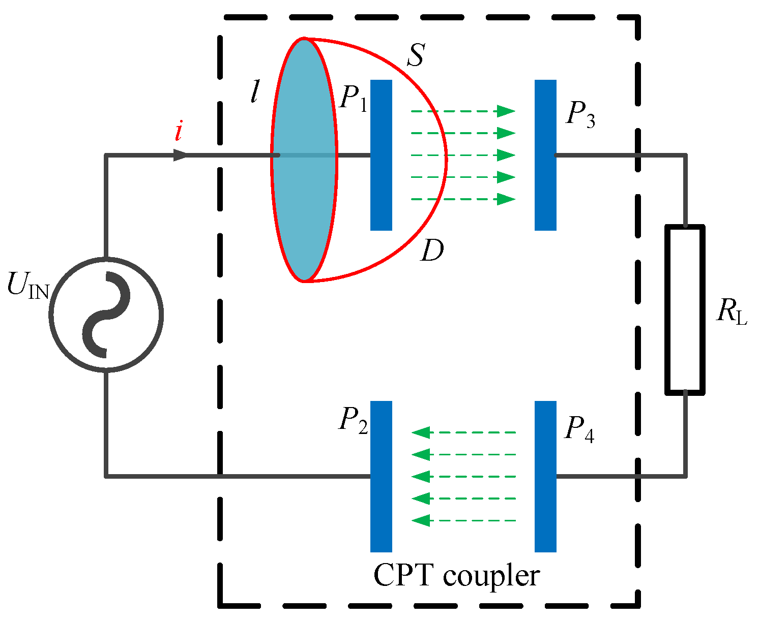
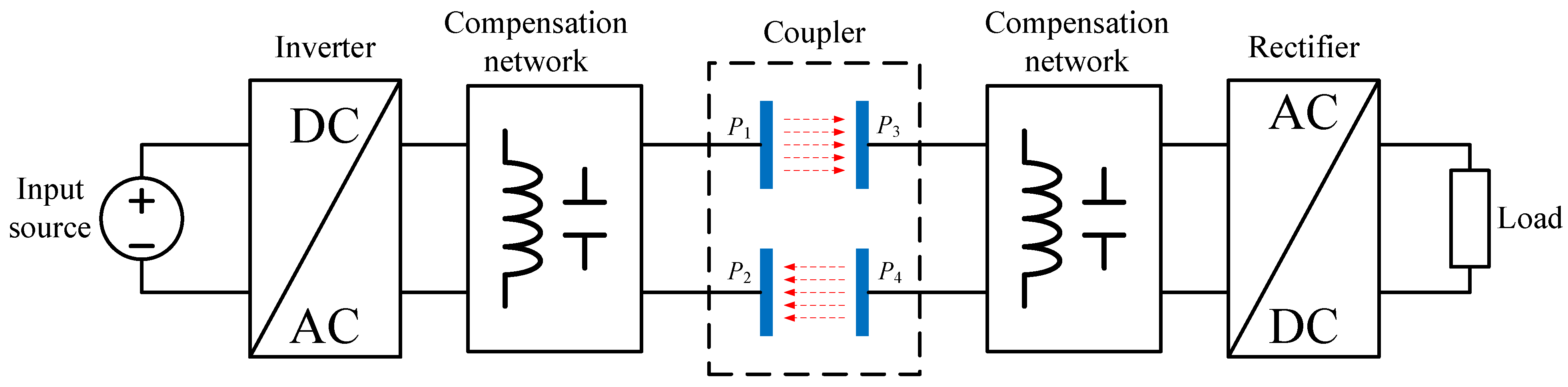
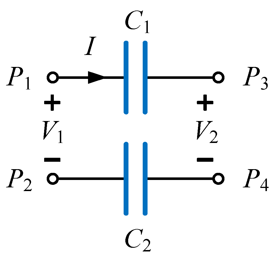
2. Basic Principle of CPT System

Research on the CPT system started relatively late compared with that of the IPT system. Unlike IPT, which uses a magnetic field as the transmission medium, CPT adopts an electric field to achieve power transfer [12,13]. IPT and CPT are dual relationships. The basic principle of the CPT system is similar to IPT. A general circuit of the CPT system is shown in Figure 1, where two pairs of metal plates are connected in series, forming a CPT coupler.
The coupling coupler is generally composed of the aluminum plate or copper plate as a channel for wireless power transfer. According to Maxwell’s full current theorem:
l H d l = S J d S + S D t d S
The line integral of the magnetic field intensity H along any closed curve l is equal to the total current passing through the area S surrounded by the path. The first term on the right of Equation (1) is the conduction current flowing through the conductor, and J is the conduction current density. The second term of Equation (1) is the displacement current, which is equal to the conduction current of the simultaneous circuit. D t is the displacement current density, which is equal to the change rate of the electric flux density D. The differential form of the full current theorem is:
× H = J + D t
Equations (1) and (2) not only explain the problem of discontinuous capacitive current from the micro perspective, but also provide an effective functional equation for the CPT system to quantitatively describe how power is transmitted from plate P1 to P3. When the alternating voltage excitation is stressed on the electrode plates, the electric flux density between the electrode plates changes to form a displacement current and achieves a wireless power transfer based on the CPT system.
Figure 2 shows a typical structure of a CPT system, which is composed of a DC power supply, high-frequency inverter, transmitter compensation topology, coupling coupler, receiver compensation topology, rectifier and load. The DC power supply provides energy for the CPT system. The inverter inverts the DC source into high-frequency AC of hundreds of kHz to MHz. Then, under the action of compensation topology, the output voltage level of high-frequency AC becomes suitable without high-order harmonic voltage excitation. The coupling mechanism is a channel for wireless energy transmission. Similar to the transmitter compensation topology, the receiver compensation topology also plays the role of voltage regulation and tuning. The rectifier forms a dual relationship with the inverter to convert AC into DC and provide DC source for the load.
In order to intuitively describe the working principle of the CPT coupler, a coupler model with two capacitors connected in series, as shown in Figure 3, is used to analyze the transfer capability. The cross-coupling effect between the plates in Figure 2 is ignored. C1 and C2 denote the coupling capacitance of the coupler. Voltage V1 and V2 are the input and output voltage on the transmitter and receiver sides, respectively. I is the current flowing through the CPT coupler. ω is the switching angular frequency. Assuming that V1 is the reference voltage, V2 and V1 are out of phase by θ.
According to the fundamental theorem of KCL and KVL, the current I can be presented as:
I = j ω ( C 1 C 2   C 1 + C 2   ) ( V 1 V 2   )
To simplify the system analysis, the active power consumed on the coupler is ignored. Therefore, the active power transmitted by the transmitter is equal to the active power received by the receiver and equal to the transfer power PC.
P C = R e ( V 1 ( I ) * ) = R e ( V 2 ( I ) * ) = R e ( V 1 ( j ω C M V 1 j ω C M V 2 ( cos ( θ ) + j ω sin ( θ ) ) ) ) = R e ( V 2 ( cos ( θ ) + j ω sin ( θ ) ( j ω C M V 1 j ω C M V 2 ( cos ( θ ) j ω sin ( θ ) ) ) ) ) = ω C M V 1 V 2 sin ( θ )
As shown in Equation (4), the active power PC transmitted through the coupling mechanism is positively related to the mutual capacitance, system operating angular frequency, coupler excitation voltage and voltage phase angle. As the mutual capacitance of the coupling mechanism is generally in pF to nF, the working frequency of the CPT system is higher than that of the IPT system, which can usually be up to several hundred kHz or even MHz. For the kW CPT system, the coupler voltages are also improved to kV level, which is required to consider the components’ masteries and system design, in order to avoid break down risks [14].

3. Theoretical Research on CPT System

Throughout the theoretical research of the CPT system, scholars have mainly focused on the coupler design, high-frequency converter, compensation network, control method, etc. The following section will present the theoretical research results of the CPT system from these aspects.

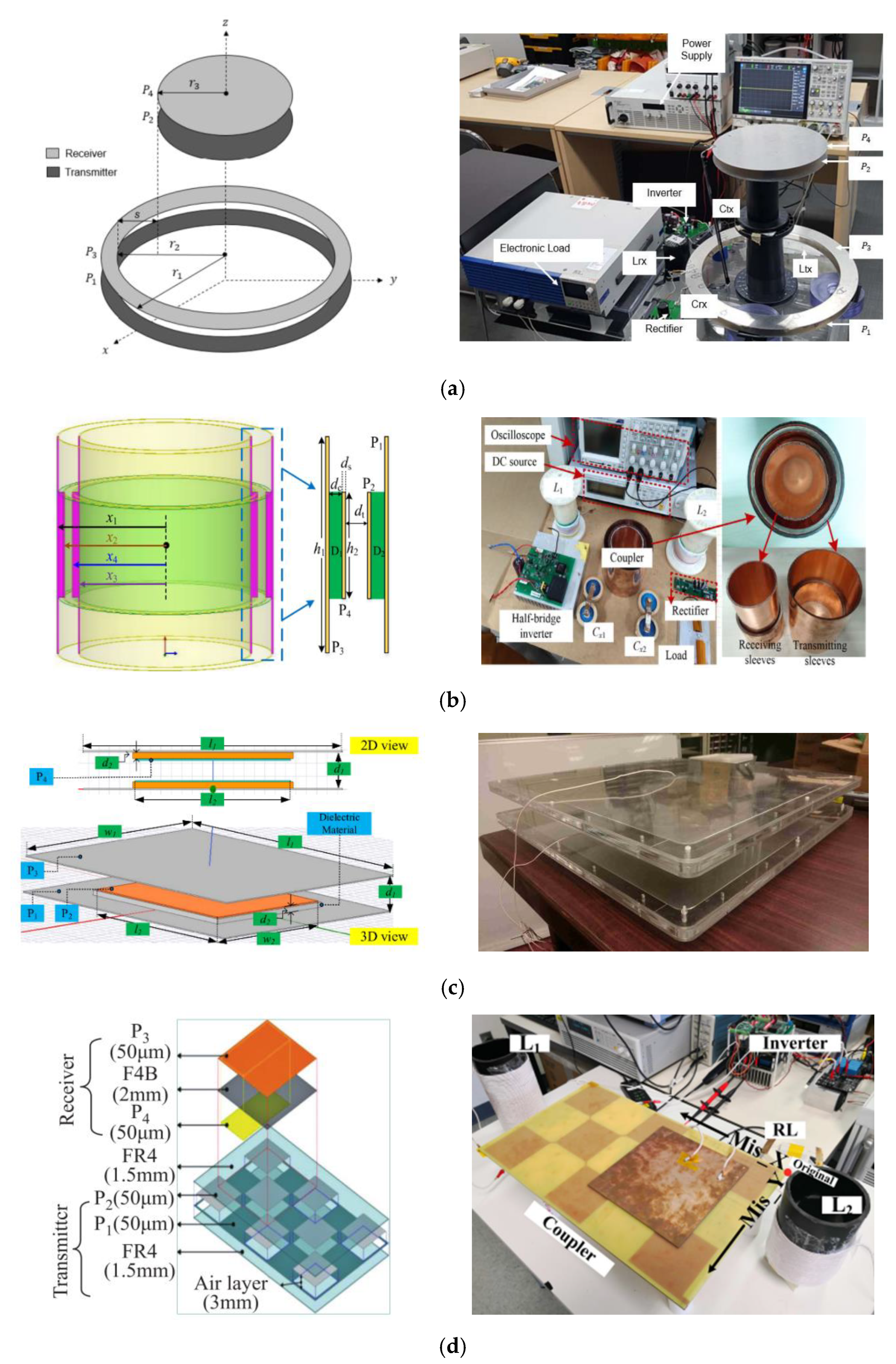
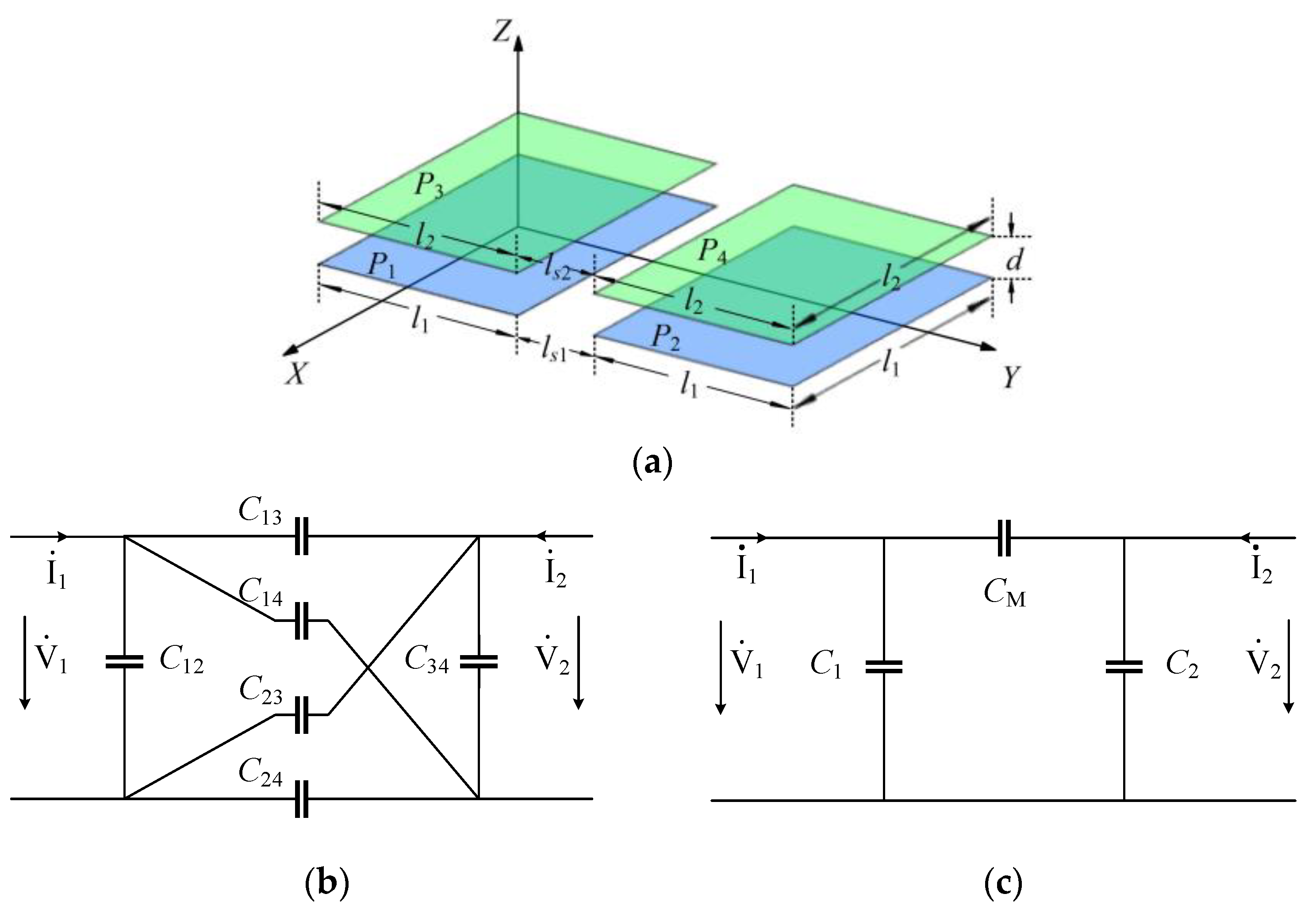
3.1. CPT Coupler Design

The coupling mechanism of the CPT system is usually composed of multiple metal plates. The transferability of the CPT system largely depends on the value of the coupling capacitor. The coupling capacitor is closely related to the structure of the coupling mechanism, transfer distance, dielectric constant of the transfer medium and other factors. In this review, the coupling mechanism of the CPT system is classified according to three criteria: the number of metal plates, the space layout of the plates, and the shape of the plates. Regarding the number of metal plates, the coupling mechanism can be divided into a two-plate structure [15], four-plate structure [16,17,18,19,20,21], six-plate structure [22,23], etc. The four-plate structure is most commonly used to form a current loop for the capacitive power transfer.
In addition, according to the different distribution positions of the coupler plates in space, the coupling mechanism can also be divided into a parallel coupler structure and a stacked coupler structure. Because the capacitive coupling coupler has good plasticity, a CPT coupler can be designed in different shapes such as a rectangular structure [24], circular structure [25], strip coupler [26], three-dimensional coupler [27], disc coupler [28], etc. The commonly used coupling mechanisms of the CPT system are shown in Figure 4.
When performing theoretical analysis, an equivalent circuit model of the electric field coupler of the CPT system is usually constructed. For an IPT system, a T-model with three inductors is usually used to simplify the system analysis. Due to the dual relationship between the IPT and the CPT system, some scholars have proposed the equivalent π-model for the four-plate CPT system in recent years [16].
There will be a coupling capacitor between every two plates of the CPT coupler. For a typical four-plate coupler, as shown in Figure 5a, it is a total of six coupling capacitors, as shown in Figure 5b. The π-model can be used to simplify this structure, as shown in Figure 5c. C1, C2, CM in the equivalent π model can be represented as Equation (5).
C 1 = C 12 + ( C 13 + C 14 ) ( C 23 + C 24 ) ( C 13 + C 14 ) ( C 23 + C 24 ) C 2 = C 34 + ( C 13 + C 24 ) ( C 14 + C 24 ) ( C 13 + C 14 ) ( C 23 + C 24 ) C 1 = C 13 C 24 C 14 C 23 C 13 + C 14 + C 23 + C 24 K C = C M C 1 C 2
Further, the π-model can be transferred to the voltage- or current-controlled model, as shown in Table 1. The equivalent model for the four plate CPT system coupler can be expanded to and used to analyze couplers with other numbers of plates [17,18].

3.2. High-Frequency Converter

Because the CPT system is based on a high-frequency alternating electric field to achieve the wireless power transfer from a power source to the load, high-frequency power converters are essential parts of the CPT system, in order to convert a low-frequency or DC input into a high-frequency source on the sending side, and vice versa on the receiving side.
High-frequency inverters can be divided into full-bridge inverters [31] and half-bridge inverters [32]. Due to their easy control and high-power density, full-bridge inverters have become the most widely used power converters in CPT systems for medium and high-power applications. Full-bridge inverters can be further divided into voltage-type full-bridge inverters [33,34,35,36] and current-type full-bridge inverters [37,38] according to whether a large inductive element is used between the inverter and the DC voltage source. The voltage-type full-bridge inverter is composed of four identical MOSFETs in series and then in parallel. The output voltage of the voltage-type inverter is a rectangular wave that is independent of the load. Reference [39] designed a voltage-type full-bridge inverter CPT system based on CLLC compensation topology for electric vehicle charging. The system can achieve a power transmission of 2.57 kW with an efficiency of 89.3% under a 150 mm air gap. The structure of the current-type full-bridge inverter is equivalent to connecting a large-value inductance element in series between the voltage-type full-bridge inverter and the DC voltage source. The output current is a rectangular waveform.
A half-bridge inverter is structurally equivalent to replacing the two MOSFETs in a voltage-source full-bridge inverter with two capacitors or inductors. Half-bridge inverters can also be further divided into voltage-mode half-bridge inverters [40,41] and current-mode half-bridge inverters [42], depending on the reactive components included. The voltage-type half-bridge inverter is structurally equivalent to replacing the two MOSFETs on the right side of the full-bridge inverter with two capacitive elements, and its output is only half of the voltage-type full-bridge inverter, so it is generally applicable for small and medium power applications. In [41], a CPT system based on a voltage-type half-bridge inverter circuit was designed, which achieved 160 W power transmission, and the efficiency was as high as 88.2%; the current-type half-bridge inverter is structurally equivalent to using two inductive elements. Replacing the upper two MOSFETs in the full-bridge inverter is characterized by soft-switching oscillation that can be achieved through self-excited oscillation without external control signals.
In addition to common bridge-type inverters, power amplifiers such as class D, class E, class E2, and class ϕ can also achieve a high-frequency conversion [43,44,45,46,47,48,49,50] that also can be used in CPT systems. Class E amplifiers have remarkable features such as high frequency, high efficiency, and simple structure, and can be soft-switched to reduce switching losses and improve system efficiency. However, the conditions for soft switching of class E amplifiers are very strict, and the switching stress is very high. Reference [43] proposed a CPT system based on class E. Reference [49] designed a CPT system based on class E2 amplifier. The power transmission of 330 W was achieved, and the efficiency reached 90%. In general, the CPT system still generally uses the full-bridge inverter circuit, especially in high-power applications.
At present, uncontrolled rectifiers in the CPT system are usually utilized, and there is little literature about the controlled rectification of the CPT system. The coupling capacitance of the CPT system is small, which makes the operating frequency of the CPT system much higher than that of the IPT system. Therefore, when designing the power converter for the CPT system, it must consider the influence of parasitic capacitance and parasitic inductance in semiconductor switching devices on the circuit at high-frequency working conditions.

3.3. Compensation Network

The CPT system adopts different compensation topologies based on the converters used. In general, the compensation topology of the CPT system can be divided into two categories: resonant compensation and non-resonant compensation.
For CPT systems using bridge inverters, resonant compensation topologies are usually adopted. The resonant compensation topology plays an important role in improving the system performance by: (1) filtering out the high-order harmonics generated by the inverter; (2) increasing the coupler voltage to improve the transfer capacity for high power applications; (3) tuning the capacitive coupler to achieve soft switching for switches and increase system efficiency; and, (4) matching the system impedance to provide the required voltage/current for the system load.
Currently, there are many different topologies applied to CPT systems, such as double-sided LC [51,52,53,54], double-sided LCC [55,56], double-sided LCLC [57,58], double-sided LCL [16,59], double-sided CLLC [39,60,61], LCLC-LC [62], LC-CLC [63], LCL-L [34], double-T resonant topology [64], multi-resonance topology [65], etc. Among them, LC-type is the basic form used to form those topologies, and the multi-stage LC structure can be used to achieve different purposes, such as boosting voltage, improving transmission efficiency, etc.
In addition to the above resonant compensation topology, some non-resonant compensation topologies, such as PWM converter, are also used to achieve capacitive power transfer. The coupler for those topologies can be regarded as an energy storage capacitor. Such common structures include Buck-Boost, Cuk, Sepic, and Zeta. By controlling the switching duty cycle, the desired output power can be achieved through capacitive power transfer. Reference [66] proposed a single active switch CPT topology based on a DC chopper circuit, which achieved a power transmission of 1 kW with a transmission efficiency greater than 90%. This kind of CPT system based on a DC chopper circuit has the advantages of simple structure and low parameter sensitivity, but requires a large mutual capacitor which is usually at nF level, which limits the application scenarios.
Table 2 summarizes common resonant compensation topologies in CPT systems and their related performances. Different compensation topologies can be chosen and designed based on the needs of actual application scenarios.
When designing and selecting the compensation topology for the specified CPT system, it is usually necessary to use circuit software such as MATLAB Simulink, Proteus, and Multisim, to simulate the overall circuit topology to calculate the system performance of transmission power and system efficiency under the used compensation topology.

3.4. Control Method

In the practical application of the CPT system, it is inevitable to encounter the situation of coupler misalignment or load variation, which may affect the system resonance condition and further reduce system output power or the transmission efficiency. To counter the several undesirable situations mentioned above, a control method can be used, such as tracking the maximum efficiency power of the system, controlling power flow, or frequency tracking. Reference [67] proposed a disturbance and observation algorithm to control the duty cycle to track the maximum power when the load changes. The proposed system could maintain a maximum power transmission operation of 10 W within a large load variation range of 5–500 Ω, and the power efficiency reached about 70%. This control method required additional DC–DC circuits and communication sampling circuits to be added to the original system circuit, which increased the system complexity and system losses. Reference [68] introduced a bidirectional power flow closed-loop control method based on the phase-shift control method, which was mainly aimed at electric vehicle charging applications with G2V and V2G power flow capabilities. The biggest disadvantage of this method was that when the phase angle was very small, it would induce certain high-order harmonics, and then the resonance state of the system would be destroyed. Based on the obtained system space state model, ref. [69] designed a linear quadratic Gaussian (LQG) controller to perform the automatic adjustment of the system frequency, so that the system always works in the resonance state. Reference [70] proposed an adaptive multi-loop controller for CPT systems, which combined continuous frequency tracking and matching network tuning at the primary and secondary ends to adjust the target under optimal power transfer conditions current/power to the receiver. In addition to the above methods, PWM control [71], PFM control [72] and other methods can also be used to control the target parameters of the system. In general, there are few studies on CPT system control at present, and of those, most are focused on single-target control for static power supply systems.

4. Key Technology Research

4.1. System Modeling

The CPT system mainly adopts the approximate linear equivalent method to obtain the linear time-invariant model. The fundamental harmonic approximation (FHA) method is the most widely used modelling method [73]. The FHA is a simple analysis method that only uses the fundamental components of the voltage or current to analyze the system characteristics. It is based on the AC impedance model of the system and can calculate the steady-state response of the system under the excitation of the fundamental wave. However, this method ignores the influence of higher harmonics in modeling and analysis, so it has a large deviation in analyzing the soft switching frequency. In addition to the FHA analysis method, ref. [74] uses filtering theory to analyze the relationship of the CPT coupler, matching network and the termination resistance. This method enables designers to quickly determine the coupling coupler parameters and system matching network under the optimal frequency response.
In addition to the above mentioned methods, the generalized space average method [75], the coupled mode theory [76], the vibration theory [77], and the fractional order theory [78] can also be used to model and analyze the CPT system.

4.2. System Efficiency Optimization

System efficiency is an important factor in designing and applying the CPT system, and how to optimize system transmission efficiency is important to research work. Although researchers have conducted a large amount of work to improve system performance, optimization of the transmission efficiency of the CPT system has just begun. At present, most of the efficiency optimization methods in CPT systems can be concluded as: (1) To optimize the design of system parameters, ref. [79] considered the ratio of reactive power in the compensation network to the transmission power as the optimization goal, and proposed a two-stage optimization method. A CPT system with a coupling capacitance of 16 pF was built under an operating frequency of 1 MHz. The built system could achieve a 3 kW power transmission with an efficiency of 95.7% under the gap distance of 100 mm; (2) Tracking the optimal load. Reference [80] verified the existence of the optimal load of the CPT system by both experiment and theory. In the case of the optimal load, when the system transmission power was 10 W, the efficiency was up to 89.3%. When the system transmission power was 100 W, the efficiency was 93.02%. To keep high efficiency under the variation of the load, ref. [81] proposed a state feedback control model using a linear quadratic regulator (LQR) and sum-pole configuration method.
In general, the optimization of CPT system efficiency is a hot research topic, which has attracted the attention of scholars in recent years, and the research results are relatively rich. However, a much work is needed to improve the system efficiency. It is generally believed that the system loss mainly derives from the parasitic resistance of compensation components in the system network, including compensation inductors, capacitors and switch devices, while ignoring the loss of the coupling mechanism. Research on the loss model of the coupling mechanism will be a direction worthy of attention in the future.

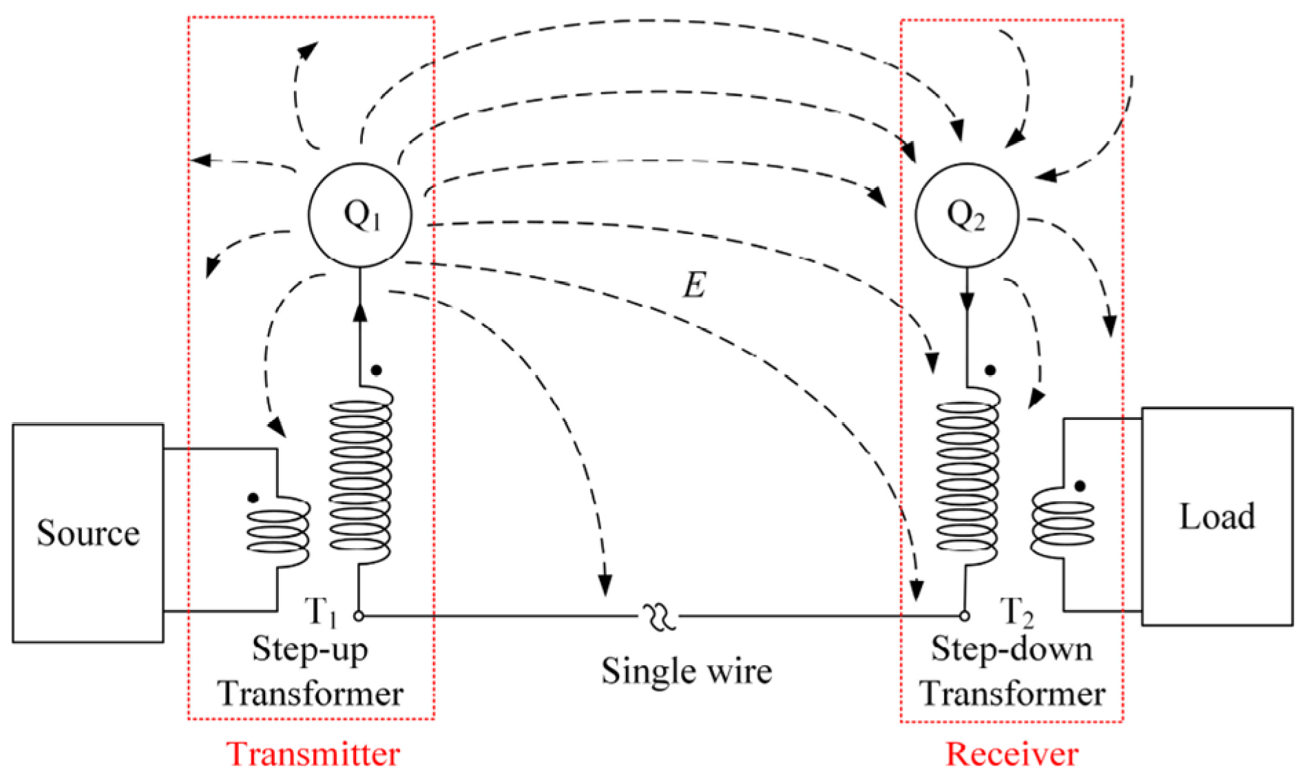
4.3. Single-Capacitor CPT System

In essence, CPT technology uses the coupling capacitor formed by the coupling mechanism to construct a complete electrical circuit to achieve wireless power transfer. Therefore, a CPT system coupler usually requires four or more plates. When there is more than one pair of coupling plates in the transfer system, the cross-coupling of multiple coupling plates will increase the complexity of the system design and affect the power property. Contrary to the traditional mutual-plates CPT system, the single-capacitor CPT system, or is named, a two-plates CPT system, uses ground working with one pair of pates to form a capacitor to form a complete electrical circuit.
The analysis method suitable for the traditional CPT system cannot be directly applied to model and analyze the single-capacitor CPT system. Reference [15] established a model of a single-capacitor system CPT system and revealed its power transmission property of strong coupling to the ground. Reference [82] proposed a new mid-range air-gap single-capacitor CPT system in which two metal blocks were used to form a virtual capacitor return route. Therefore, the traditional four-plate structure was simplified to a two-plate structure. Reference [83] designed and built an experimental circuit of a single-capacitor CPT system with an achieved power transfer of 3.8 W. Reference [84] proposed a two-plate CPT system for electric vehicle charging applications. The experimental setup achieved a power transmission of 350 W with a DC-DC efficiency of 74.1% when the air gap distance was 110 mm.
For the traditional CPT system, the transmission power and efficiency of the system will be greatly reduced with the increase in the transfer distance. Therefore, the transmission distance of current CPT systems is mostly in centimeters. Based on coupled-mode theory, ref. [85] proposed a nonlinear isochronous symmetric model as shown in Figure 6. A high-time-symmetric model for the single-capacitor CPT system is achieved and constant transmission efficiency was obtained under the condition of variable transfer distance. Theoretical analysis and circuit simulation showed that when the transmission distance was about 34 m, the transmission efficiency was kept at 60% under the condition of constant output power and without any resonant circuit. Reference [86] proposed a robust single-capacitor CPT system. The simulation results showed that the system could achieve wireless power transfer within a range of 31 m. The efficiency was constant at 50%. In the future, an experiment could be conducted to verify the simulation and analysis results. In general, the research for the single-capacitor CPT system is still in the preliminary exploration stage.

4.4. IPT and CPT Combined System

The coupling mechanism of the CPT system is composed of metal plates, and coupling capacitance will be formed between the metal plates. Therefore, the CPT coupler is capacitive and needs to be compensated by the inductor. In contrast, the coupling mechanism of the IPT system is composed of coils. The IPT coupler is inductive, and the capacitor is required to resonate the network for the IPT system. Taking into account the condition mentioned above, the IPT and CPT couplers can be combined into a hybrid WPT system to achieve mutual compensation [87]. The hybrid WPT system combining the IPT and CPT systems was first proposed in [88]. Reference [89] proposed a new coupling mechanism that transferred electrical power by using both magnetic and electric fields. Based on this coupling mechanism, a combined system could achieve 100 W output power with an efficiency of 73.6% under an air gap of 18 mm.
In recent years, a variety of combined systems with magnetic field coupling and electric field coupling were proposed to make full use of the advantages of the IPT system and the CPT system. The combined system is mainly used to achieve the following goals: (1) To improve the transmission power [88,90,91]. Reference [90] proposed an inductive and capacitive hybrid WPT system that could improve the system transfer capability using IPT and CPT channels. The achieved transmission power was 1.1 kW, and DC–DC efficiency was 91.9%; (2) Parallel transmission of electric power and signal [92]. A combined WPT system was proposed in [92]. A signal transmission channel was constructed by using the parasitic capacitance of the coil and shielding metal plates. A transfer power of 40 W and a data transmission rate of 230 kbs were achieved; (3) To improve the coupler misalignment ability [93,94]. An inductance–capacitor hybrid WPT system was constructed in [94], which improved the coupler anti-misalignment ability. When the change of the coupling plate spacing was within 0–270 mm, the variation of the output power did not exceed 10% of the nominal output.
The combined WPT system has a better system performance than the single IPT or CPT system. However, the coupling mechanism of the hybrid WPT system includes both the induction coil of the IPT system and the coupling plates of the CPT system, the system is more complicated, and the volume of the coupler is larger. To simplify the coupling mechanism of the combined WPT system, ref. [89] proposed a compact combined coupling mechanism where the magnetic and electrical fields can be simultaneous to transfer electrical power.
In general, the combined system has better characteristics. However, there are some disadvantages that need to be studied and solved: (1) The optimal design of the coupling mechanism: the magnetic field coupler and the electric field coupler coexist, which increases the occupied space and the electromagnetic radiation; (2) Parallel and separate control of transmission channels. The combined WPT system has two power transfer channels which may present multiple power transfer modes. To meet various application requirements under different load conditions, an effective control method for parallel and separate energy transmission channels needs to be developed in the future.
This review summarizes some research of combined WPT systems in recent years in Table 3.

4.5. Constant Current/Voltage Charging

The battery charging process includes two stages of constant current (CC) and constant voltage (CV) charging. When the CPT system is used to supply power to charge the battery load, constant voltage/current output should be considered. Much work has been undertaken to achieve CC or CV output.
For charging a single battery with a single transmitter, ref. [96] proposed a constant voltage output system. The resonance network was used to convert the current source input voltage source into a constant current and then to the constant voltage output for charging the battery, ignoring the variation of coupling capacitance and load. Reference [53] designed a single-input single-output CPT system based on double-sided LC compensation, which achieved a constant current output under variable load. Reference [62] proposed a resonant network for the CPT system. Different resonant frequencies could be adopted to generate a constant current and constant voltage output. Reference [97] proposed an impedance matching network to generate a constant voltage output to charge a dynamic load. Reference [98] summarized different compensation topologies and proposed a specific design method for a constant current and voltage output with zero-voltage switching.
In the application of multiple load charging, ref. [99] proposed a mixed-resonant topology for constant-current multiple-pickup applications such as LED drivers, welding machines and batteries. Reference [100] proposed a multi-load capacitive power transfer (CPT) system with an SP-CL isolation compensation topology. Receivers function solely as power consumers in the proposed system, and each receiver not only supplies power to the connected load but transfers power wirelessly to the next receiver. The proposed system could achieve constant voltage output. Reference [101] designed a multi-load CPT system based on repeaters in which L compensation topology was used to compensate input and output relays, and LCL compensation topology was used to compensate relay relays. The proposed system could achieve a multi-load constant current output.
Research on the method of generating a constant voltage or current output for CPT systems has always been a hot topic in the research of CPT systems. Generally speaking, current research on the method for generating constant voltage or current output of CPT system mainly focuses on research on the compensation topology for generating constant voltage or current output.

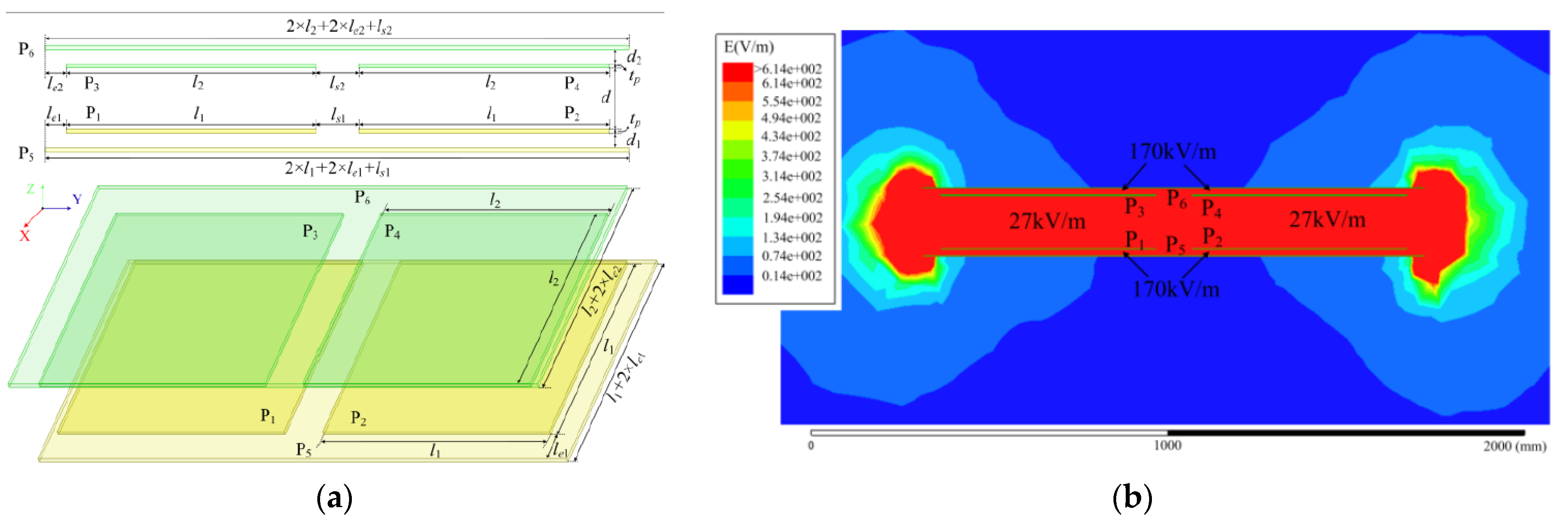
4.6. System Safety Research

The security of the CPT system has always been a key concern in the field of CPT research. The CPT system uses metal plates to form a transfer coupler and achieves wireless transmission of electric energy based on the high-frequency alternating electric field. In kW level CPT systems, the coupler voltage is often increased to improve transmission power, resulting in the voltage on the coupling plates reaching thousands of volts or even tens of thousands of volts, which has significant potential safety hazards.
When the voltage stress on the coupling plates is too high, the air medium between the plates may be broken down, resulting in overcurrent and endangering the safety of the coupler itself. Reference [102] proposed a voltage stress optimization method, which can reallocate the voltage stress of system components by adjusting system parameters; Reference [103] proposed a voltage control method for the coupling coupler of the CPT system, which can limit the voltage between the coupling plates to a safe range.
As there is a high-frequency AC electric field between the coupling plates, it is also necessary to take anti-electric shock and anti-radiation measures to reduce the harm to the human body. To prevent the harm of electric shock, the coupling plates of the system can be insulated and encapsulated. The electric field of the coupling coupler will generate distributed voltage on the surrounding metal body, and the human body may have the risk of electric shock when touching the metal body. Reference [104] established an equivalent model of human contact with the metal plates around the coupling coupler based on the human impedance model, which effectively guides the design of the CPT system from the perspective of safety.
In addition, ref. [22] used the external metal plates to shield the electric field from the harm of electromagnetic radiation, which weakened the electric field radiation to a certain extent. The schematic diagram of the coupling coupler is shown in Figure 7a, and the simulated electric field distribution between the coupling coupler is shown in Figure 7b. However, the additional shielding plate increases the volume of the coupler. In addition, the additional plate affected the coupling capacitance, making the design of the system coupler more complex; Ref. [20] proposed a staggered capacitive coupler which not only improved the system’s mutual capacitance but also significantly reduced the cross-coupling effect of the system coupling plate. Additionally, this coupler helped to reduce the radioactive electric field and thus significantly reduced the high radiation area.
To effectively simulate the electric field distribution, simulation tools such as ANSYSY Maxwell, FEKO, CST Microwave Studio and COMSOL are usually utilized.

5. Application of CPT System

The continuous development of the CPT system has attracted extensive attention from research teams around the world because of its simple structure, light weight and low cost. Research teams have not only focused on transmission distance and transmission power but have also fully explored the application scenarios with the advantages of CPT technology. This section will present the current research status of CPT technology in biomedical implants, transportation applications, line online monitoring equipment power supply, power supply for underwater equipment, and power supply application for rotary mechanism.

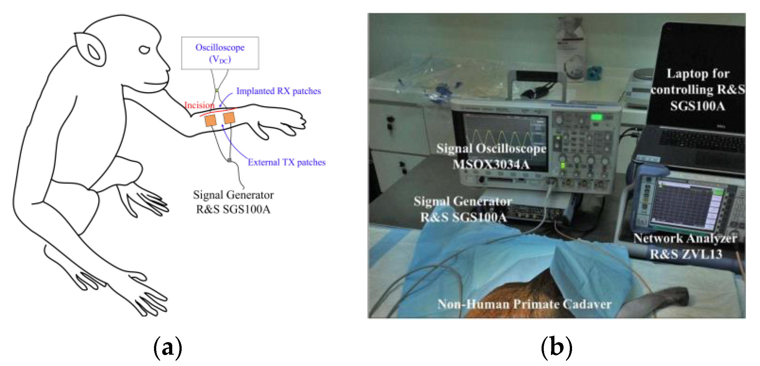
5.1. Biomedical Implants

Compared with the IPT system, the CPT system has the advantages of a simple coupling structure, low eddy current loss, and low electromagnetic radiation. It is widely used to power implantable biomedical devices [105].
Rangarajan Jegadeesan et al. of the National University of Singapore proposed a wireless power supply system based on electric field coupling using displacement current to create subcutaneous sensors. They have established a coupling model of power transmission and determined the optimal operating frequency of the system [106]. The coupling model and experimental diagrams are shown in Figure 8. Reza Erfani of Case Western Reserve University established a comprehensive circuit model of the coupling mechanism with the human tissue layer as the dielectric material [107,108] and developed a CPT power supply system suitable for human implantable medical devices in which a CMOS active rectifier is proposed to achieve dual-loop adaptive delay compensation and has automatic input frequency adaptation characteristics [109]. At present, the CPT system used in implantable biomedical devices is limited to a short-distance subcutaneous tissue sensor power supply (about 5 mm). There are no reports on the power supply of medical sensors with longer transmission distance requirements for organs. Reza Sedehi et al. of the University of Auckland proposed a CPT system for conductive tissue, which is a safe, efficient and stable energy transfer into the body for deeply implanted biomedical devices [110]. Under the limitation of IEEE C95.1, the proposed system can deliver 10 mW power into the deep body.

5.2. Transportation Applications

Due to the gradual exhaustion of traditional fossil energy in recent years, electric vehicles (EV) have flourished. Charging of EVs is a big challenge. Wireless power transfer as a charging technology has attracted much attention for EVs. The IPT system has gradually matured for charging EVs. By comparison, IPT has the disadvantage of high electromagnetic radiation, large eddy current loss, and the inability of metal obstacles to exist near the coupling area. Contrary to IPT of magnetic field coupling, CPT adopts electric field coupling, which can solve the shortcomings of IPT to a certain extent.
Takashi Ohira et al. from the Toyohashi University of Technology and Science in Japan proposed a dynamic CPT system for the battery-less EVs through the inter-board capacitator between the built-in metal of the road concrete and the car tires. The transfer power was up to 1 kW at a speed of 10 km/h [111]. The schematic diagram of the proposed system is shown in Figure 9. Reference [112] proposed an optimization method for the CPT system to reduce the voltage on the car shell during wireless charging for EVs. The car shell voltage was only 3.88 V when the output power was 1.3 kW. Aiming at the problems of small coupling capacitance and low transmission power for the CPT system to charge the EVs, Dai Jiejian et al. used the metal foil on the bumper of the electric vehicle and the metal foil on the fixed charging pile to achieve static wireless charging. The transfer power reached 1 kW with a DC–DC efficiency of more than 90% [113]. Reference [114] verified the possibility of providing 700 W power to a moving locomotive with a 24 pF coupling capacitance between the metal plates. Reference [115] proposed a dynamic capacitive power transfer system for an EV. A 150 W dynamic CPT system prototype was designed and implemented. When the receiver moved along the transmitter track, the output power changed within ±4.0% of the nominal power.

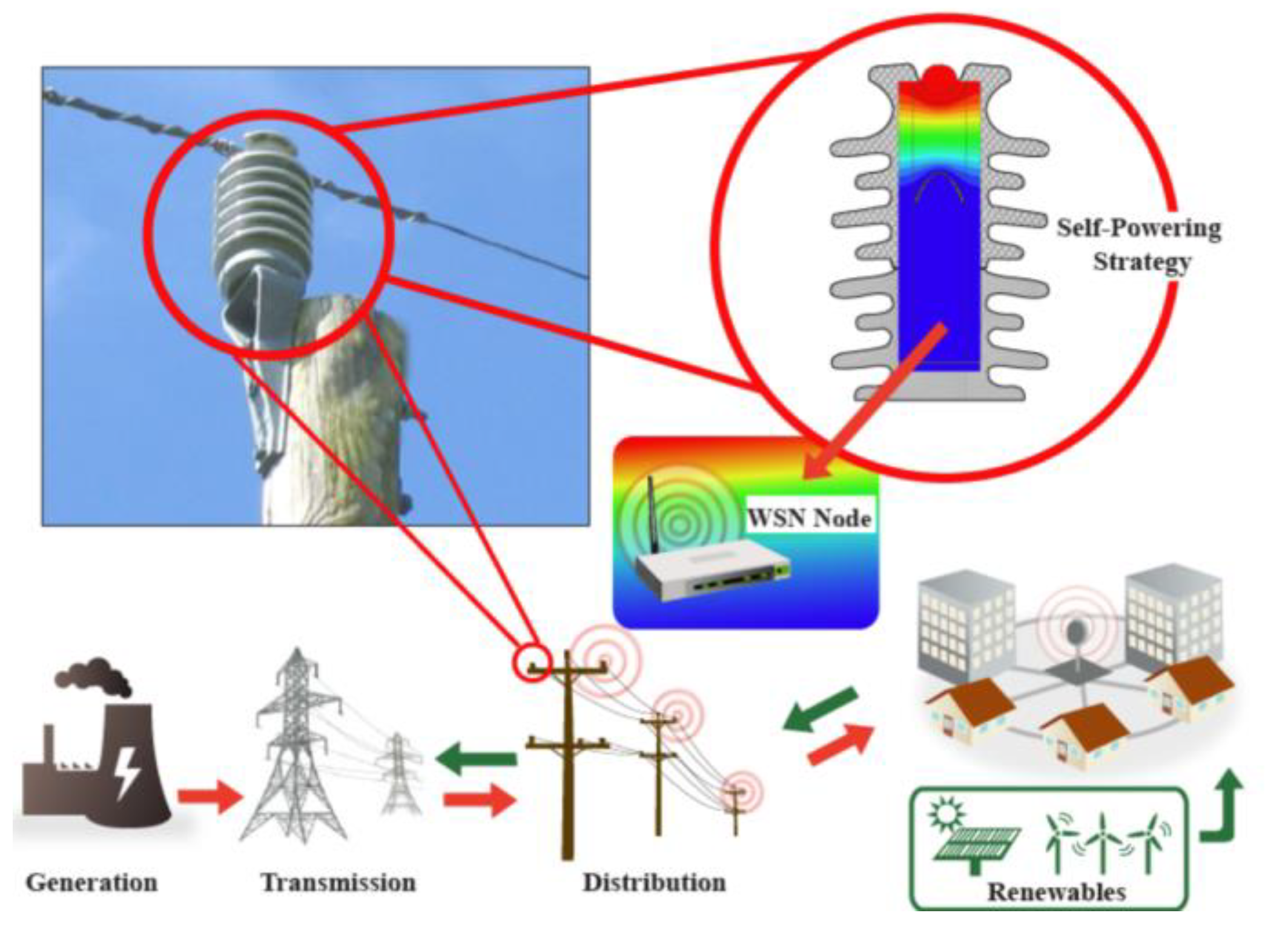
5.3. Line Online Monitoring Equipment Power Supply

In order to solve the problem of power supply for line monitoring equipment, photovoltaic cells and current transformers are mainly used to acquire electricity. However, due to the environmental and load fluctuations, the stability of the above power supply methods is relatively low. The CPT system uses electric field coupling to generate power transmission, which is stable and reliable when the input voltage is specified. Therefore, the CPT system can provide stable power for monitoring equipment. When the CPT system is adopted to power the monitoring equipment, the voltage input of the transfer coupler is provided by the high-voltage transmission line, which simplifies the transfer system structure, and only the receiver of the CPT system is needed.
Rohit Moghe et al. of Varentec Company first proposed the concept of electric field-based wireless power supply in [116], and developed a tubular energy pick up mechanism as shown in Figure 10. The effectiveness of the proposed system was experimentally verified. In addition to the tubular pick up mechanism, insulator embedded structures based on circular metal plates, multilayer cylindrical, rectangular and with higher safety, have also been developed [117,118,119,120]. The CPT system can also be applied to a low-voltage transmission line in addition to high-voltage/medium-voltage power systems. For example, ref. [120] proposed a transmission system with an output power of 47 μW by using a 60 cm aluminum foil adhered to a 220 V AC transmission line, which can meet the power supply requirements of monitoring sensors. Reference [121] also studied the monitoring strategy using CPT technology.

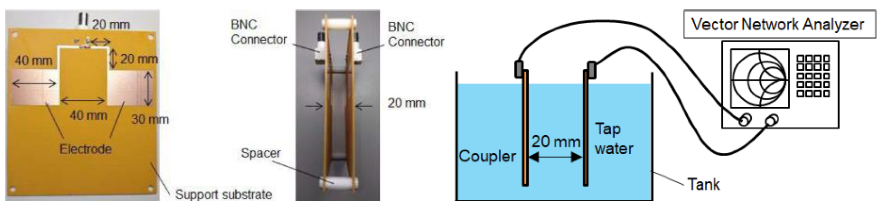
5.4. Power Supply for Underwater Equipment

In order to solve the problem of power supply for underwater equipment, the research and application of underwater WPT systems has also been a hot topic in recent years. Since the medium of water is different from that of air, the coupling capacitance of the CPT system can be effectively increased in the water medium [122]. Therefore, the transmission capacity can be significantly improved. It is of great significance to power equipment practically in water media such as fresh water and sea water.
Reference [123] proposed an underwater CPT system. The coupling coupler of the proposed system and the underwater test schematic diagram is shown in Figure 11. It was found that the transmission distance between the plates was the key factor in designing the compensation circuit. The water medium between the coupler plates affects the transmission characteristics. The stray capacitance between the two plates also affects the power transfer. Based on the frequency characteristics of the dielectric loss coefficient, ref. [124] discussed the influence of different factors of underwater electric field coupling on the transfer efficiency. Using 3D simulation and measurements, the S-parameters of the parallel-plate galvanic coupler were converted to achieve maximum efficiency. The maximum transfer efficiency of the CPT system in freshwater was deduced through simulation and measured results. Reference [125] deduced the relationship between the coupling coefficient and the operating frequency of the system based on the equivalent circuit of the coupling coupler and explained the key factors to improve the coupling coefficient.

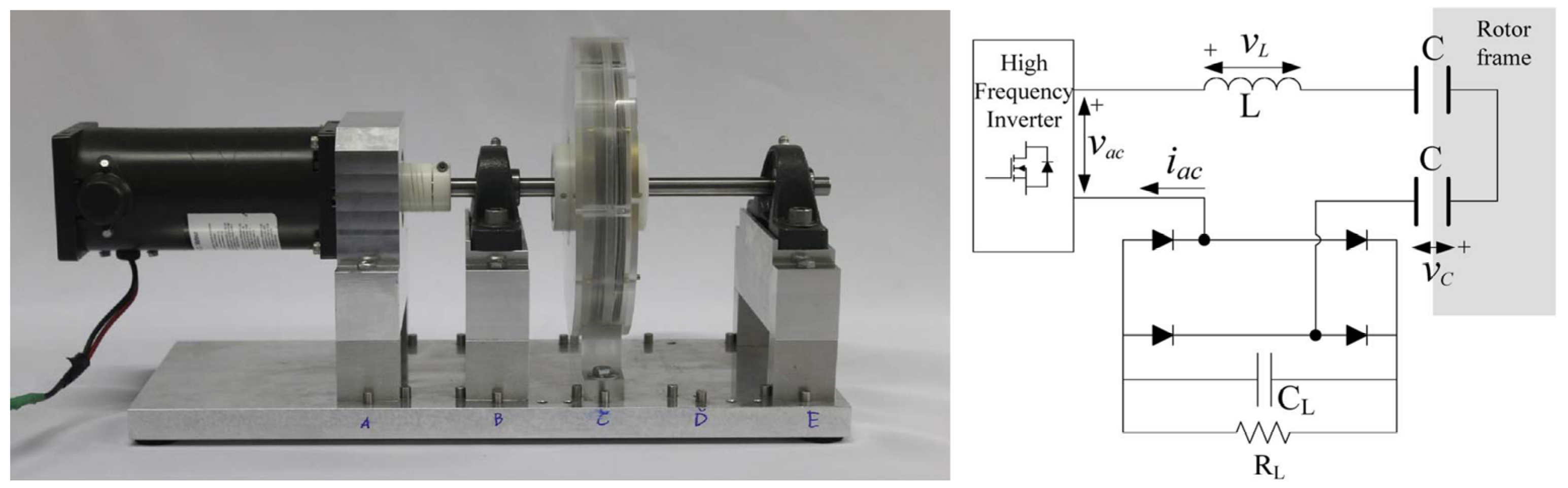
5.5. Power Supply Application for Rotary Mechanism

In order to switch the current direction for DC motors, brushes must be used for traditional continuous switching, which will cause brush friction, accelerate aging and generate sparks. To solve this problem, the CPT system was proposed to power the rotating mechanisms of the DC motors, which could effectively remove the friction loss, unreliable contact, sparks and other problems existing in the brush method. The CPT system has also been used to other rotary applications [126,127,128].
In the [126], the CPT system was used to generate wireless power transmission between the static surface and moving surface of an aerodynamic fluid bearing. The pneumatic fluid-bearing experimental device diagram and its circuit structure diagram are shown in Figure 12. Reference [127] designed a CPT power supply system suitable for three-dimensional space rotation applications. When the receiving plate is within a certain rotation angle range, the capacitance of the coupler can be constant, to ensure that the load can still receive power at a stable rate when the load is rotating. Reference [128] proposed a three-phase resonant capacitor power transfer system, which solved the problem that the existing rotating CPT plate concentric structure showed unbalance, leading to ground return common-mode current.

6. Conclusions and Further Work

With the rapid development of semiconductor switching devices and power electronic control technology, wireless power transfer technology has become more efficient, safer and reliable, and will definitely become the mainstream direction in the field of power supply. CPT technology has also achieved tremendous development. In contrast, some research should be carried out in these further areas: 1. Design and optimization of switching devices under high power requirements. Compared with the IPT system, the CPT system requires a higher switching frequency. The efficiency and thermal stability of the device are one of the important research directions; 2. The design and optimization of the coupler suitable for complex environments. The capacitance generated between the metal plates of the CPT coupler achieve the energy transfer channel. In contrast, the external conductor is very easy to generate additional parasitic capacitance with the coupler, which may affect the system characteristics. Therefore, how to shield, reduce or transform the influence of the external environment on the coupling mechanism is very critical; 3. Efficient and stable compensation network topology. Although the IPT system has a mature compensation network analysis, it cannot be directly applied to the CPT system due to the unique working characteristics of the CPT system. It is necessary to carry out a complete compensation network analysis based on the system transfer characteristics, electrical safety and system stability of the CPT system; 4. System efficiency improvement. At present, the efficiency research of CPT is mainly focused on the analysis and optimization of compensation topology parameters. At the same time, the system coupler, converter circuit and overall optimization have not been considered.
Although present research into the CPT system is still in the preliminary stage, it will definitely be the focus of future research teams due to its advantages in specific applications, and will certainly promote the wider application of the CPT system.

Author Contributions

Conceptualization, B.L.; methodology, Z.W.; software and hardware preparation, Y.Z.; validation, X.H.; writing—original draft preparation, Z.W.; writing—review and editing, Z.W.; supervision, R.M. All authors have read and agreed to the published version of the manuscript.

Funding

This research received no external funding.

Conflicts of Interest

The authors declare no conflict of interest.

References

  1. Zhang, Z.; Pang, H.; Georgiadis, A.; Cecati, C. Wireless Power Transfer—An Overview. IEEE Trans. Ind. Electron. 2019, 66, 1044–1058. [Google Scholar] [CrossRef]
  2. Patil, D.; McDonough, M.K.; Miller, J.M.; Fahimi, B.; Balsara, P.T. Wireless Power Transfer for Vehicular Applications: Overview and Challenges. IEEE Trans. Transp. Electrif. 2018, 4, 3–37. [Google Scholar] [CrossRef]
  3. Hui, S.Y.R.; Zhong, W.; Lee, C.K. A Critical Review of Recent Progress in Mid-Range Wireless Power Transfer. IEEE Trans. Power Electron. 2014, 29, 4500–4511. [Google Scholar] [CrossRef] [Green Version]
  4. Kazmierkowski, M.; Moradewicz, A. Unplugged But Connected: Review of Contactless Energy Transfer Systems. IEEE Ind. Electron. Mag. 2012, 6, 47–55. [Google Scholar] [CrossRef]
  5. Minnaert, B.; Stevens, N. Optimal Analytical Solution for a Capacitive Wireless Power Transfer System with One Transmitter and Two Receivers. Energies 2017, 10, 1444. [Google Scholar] [CrossRef] [Green Version]
  6. Lu, F.; Zhang, H.; Mi, C. A Review on the Recent Development of Capacitive Wireless Power Transfer Technology. Energies 2017, 10, 1752. [Google Scholar] [CrossRef] [Green Version]
  7. Dai, J.; Ludois, D.C. A Survey of Wireless Power Transfer and a Critical Comparison of Inductive and Capacitive Coupling for Small Gap Applications. IEEE Trans. Power Electron. 2015, 30, 6017–6029. [Google Scholar] [CrossRef]
  8. Leung, H.F.; Hu, A.P. Modeling the Contact Interface of Ultrasonic Power Transfer System Based on Mechanical and Electrical Equivalence. IEEE J. Emerg. Sel. Top. Power Electron. 2018, 6, 800–811. [Google Scholar] [CrossRef]
  9. Zhang, K.; Du, H.; Luo, B.; Mai, R.; Song, B.; Hu, A.P. Optimal Load Determination of Capacitor–Inductor Compensated Capacitive Power Transfer System with Curved-Edge Shielding Layer. Electronics 2021, 10, 2961. [Google Scholar] [CrossRef]
  10. Jin, K.; Zhou, W. Wireless Laser Power Transmission: A Review of Recent Progress. IEEE Trans. Power Electron. 2019, 34, 3842–3859. [Google Scholar] [CrossRef]
  11. Krasnok, A. Coherently Driven and Super directive Antennas. Electronics 2019, 8, 845. [Google Scholar] [CrossRef] [Green Version]
  12. Kracek, J.; Svanda, M. Analysis of Capacitive Wireless Power Transfer. IEEE Access 2019, 7, 26678–26683. [Google Scholar] [CrossRef]
  13. Wang, Y.; Zhang, H.; Lu, F. Review, Analysis, and Design of Four Basic CPT Topologies and the Application of High-Order Compensation Networks. IEEE Trans. Power Electron. 2022, 37, 6181–6193. [Google Scholar] [CrossRef]
  14. Luo, B.; Hu, A.P.; Munir, H.; Zhu, Q.; Mai, R.; He, Z. Compensation Network Design of CPT Systems for Achieving Maximum Power Transfer Under Coupling Voltage Constraints. IEEE J. Emerg. Sel. Top. Power Electron. 2022, 10, 138–148. [Google Scholar] [CrossRef]
  15. Zou, L.J.; Zhu, Q.; Van Neste, C.W.; Hu, A.P. Modeling Single-Wire Capacitive Power Transfer System with Strong Coupling to Ground. IEEE J. Emerg. Sel. Top. Power Electron. 2021, 9, 2295–2302. [Google Scholar] [CrossRef]
  16. Zhang, H.; Lu, F.; Hofmann, H.; Liu, W.; Mi, C. A 4-Plate Compact Capacitive Coupler Design and LCL-Compensated Topology for Capacitive Power Transfer in Electric Vehicle Charging Applications. IEEE Trans. Power Electron. 2016, 31, 8541–8551. [Google Scholar] [CrossRef]
  17. Dias Fernandes, R.; Matos, J.N.; Borges Carvalho, N. Resonant Electrical Coupling: Circuit Model and First Experimental Results. IEEE Trans. Microw. Theory Tech. 2015, 63, 2983–2990. [Google Scholar] [CrossRef]
  18. Huang, L.; Hu, A.P. Defining the mutual coupling of capacitive power transfer for wireless power transfer. Electron. Lett. 2015, 51, 1806–1807. [Google Scholar] [CrossRef]
  19. Huang, L.; Hu, A.P.; Swain, A.K.; Su, Y. Z-Impedance Compensation for Wireless Power Transfer Based on Electric Field. IEEE Trans. Power Electron. 2016, 31, 7556–7563. [Google Scholar] [CrossRef]
  20. Liu, Y.; Wu, T.; Fu, M. Interleaved Capacitive Coupler for Wireless Power Transfer. IEEE Trans. Power Electron. 2021, 36, 13526–13535. [Google Scholar] [CrossRef]
  21. Wu, X.; Su, Y.; Hu, A.P.; Qing, X.; Hou, X. Multiobjective Parameter Optimization of a Four-Plate Capacitive Power Transfer System. IEEE J. Emerg. Sel. Top. Power Electron. 2021, 9, 2328–2342. [Google Scholar] [CrossRef]
  22. Zhang, H.; Lu, F.; Hofmann, H.; Liu, W.; Mi, C.C. Six-Plate Capacitive Coupler to Reduce Electric Field Emission in Large Air-Gap Capacitive Power Transfer. IEEE Trans. Power Electron. 2018, 33, 665–675. [Google Scholar] [CrossRef]
  23. Behnamfar, M.; Javadi, H.; Afjei, E. A dynamic CPT system L.C. Compensated with a six-plate capacitive coupler for wireless charging of electric vehicle in motion. In Proceedings of the 2020 28th Iranian Conference on Electrical Engineering (ICEE), Tabriz, Iran, 4–6 August 2020; pp. 1–6. [Google Scholar]
  24. Wu, X.; Su, Y.; Hou, X.; Qing, X.; Dai, X. Study on load adaptation of capacitive power transfer system with a four-plate compact capacitive coupler. Electr. Eng. 2019, 101, 733–742. [Google Scholar] [CrossRef]
  25. Park, C.; Park, J.; Shin, Y.; Kim, J.; Huh, S.; Kim, D.; Park, S.; Ahn, S. Separated Circular Capacitive Coupler for Reducing Cross-Coupling Capacitance in Drone Wireless Power Transfer System. IEEE Trans. Microw. Theory Tech. 2020, 68, 3978–3985. [Google Scholar] [CrossRef]
  26. Chen, X.; Yu, S.; Zhang, Z. A Strip-Coupler for Dynamic Capacitive Wireless Power Transfer. In Proceedings of the IECON Proceedings (Industrial Electronics Conference), Lisbon, Portugal, 14–17 October 2019; Volume 1. [Google Scholar]
  27. Zhu, Q.; Zou, L.J.; Su, M.; Hu, A.P. E-Field Analysis of a 3D Capacitive Power Transfer Configuration with Single Source Excitation. In Proceedings of the 2019 IEEE PELS Workshop on Emerging Technologies: Wireless Power Transfer (WoW), London, UK, 18–21 June 2019; pp. 253–256. [Google Scholar]
  28. Wu, X.-Y.; Su, Y.-G.; Hu, A.P.; Zou, L.J.; Liu, Z. A Sleeve-Type Capacitive Power Transfer System with Different Coupling Arrangements for Rotary Application. IEEE Access 2020, 8, 69148–69159. [Google Scholar] [CrossRef]
  29. Pamungkas, L.; Tampubolon, M.; Chang, Y.-C.; Chiu, H.-J. Resonant Network Transformation and Implementation of a Compacted Four-Plate Capacitive Power Transfer. In Proceedings of the 2019 IEEE 4th International Future Energy Electronics Conference (IFEEC), Singapore, 25–28 November 2019; pp. 1–6. [Google Scholar]
  30. Zhu, J.-Q.; Ban, Y.-L.; Zhang, Y.; Cheng, C.; Yan, Z.; Xu, R.-M.; Mi, C.C. A Novel Capacitive Coupler Array with Free-Positioning Feature for Mobile Tablet Applications. IEEE Trans. Power Electron. 2019, 34, 6014–6019. [Google Scholar] [CrossRef]
  31. Abramov, E.; Zeltser, I.; Peretz, M.M. A Network-Based Approach for Modeling Resonant Capacitive Wireless Power Transfer Systems. CPSS Trans. Power Electron. Appl. 2019, 4, 19–29. [Google Scholar] [CrossRef]
  32. Mishra, S.K.; Adda, R.; Sekhar, S.; Joshi, A.; Rathore, A.K. Power transfer using portable surfaces in capacitively coupled power transfer technology. IET Power Electron. 2016, 9, 997–1008. [Google Scholar] [CrossRef]
  33. Wang, S.; Liang, J.; Fu, M. Analysis and Design of Capacitive Power Transfer Systems Based on Induced Voltage Source Model. IEEE Trans. Power Electron. 2020, 35, 10532–10541. [Google Scholar] [CrossRef]
  34. Vu, V.-B.; Dahidah, M.; Pickert, V.; Phan, V.-T. An Improved LCL-L Compensation Topology for Capacitive Power Transfer in Electric Vehicle Charging. IEEE Access 2020, 8, 27757–27768. [Google Scholar] [CrossRef]
  35. Xia, C.; Chen, R.; Liu, L.; Lei, K.; Wu, X. Investigation of the constant-voltage, constant-current, and power characteristics of capacitive power transfer systems based on double-CLC topology. IEEJ Trans. Electr. Electron. Eng. 2018, 13, 1660–1667. [Google Scholar] [CrossRef]
  36. Li, C.; Zhao, X.; Liao, C.; Wang, L. A graphical analysis on compensation designs of large-gap CPT systems for E.V. charging applications. CES Trans. Electr. Mach. Syst. 2018, 2, 232–242. [Google Scholar] [CrossRef]
  37. Wang, Y.; Zhang, H.; Lu, F. Current-Fed Capacitive Power Transfer with Parallel-Series Compensation for Voltage Step-Down. IEEE J. Emerg. Sel. Top. Ind. Electron. 2021. [Google Scholar] [CrossRef]
  38. Maji, S.; Sinha, S.; Afridi, K.K. Roadway Embeddable Multi-MHz Capacitive Wireless Charging System with Matching Network Realized using Wiring Parasitics. In Proceedings of the 2021 IEEE Energy Conversion Congress and Exposition (ECCE), Vancouver, BC, Canada, 10–14 October 2021; pp. 5775–5780. [Google Scholar]
  39. Lu, F.; Zhang, H.; Hofmann, H.; Mi, C. A CLLC-compensated high power and large air-gap capacitive power transfer system for electric vehicle charging applications. In Proceedings of the 2016 IEEE Applied Power Electronics Conference and Exposition (APEC), Long Beach, CA, USA, 20–24 March 2016; pp. 1721–1725. [Google Scholar]
  40. Otaki, D.; Funato, H.; Haruna, J. Proposal of Capacitive Power Transfer System through Automotive Body Paintings. In Proceedings of the 2021 IEEE 30th International Symposium on Industrial Electronics (ISIE), Kyoto, Japan, 20–23 June 2021; pp. 1–6. [Google Scholar]
  41. Truong, C.-T.; Choi, S.-J. Single-Stage Duty-Controlled Half-Bridge Inverter for Compact Capacitive Power Transfer System. IEEE Access 2021, 9, 119250–119261. [Google Scholar] [CrossRef]
  42. Abdolkhani, A.; Hu, A.P.; Tian, J. Autonomous Polyphase Current-Fed Push–Pull Resonant Converter Based on Ring Coupled Oscillators. IEEE J. Emerg. Sel. Top. Power Electron. 2015, 3, 568–576. [Google Scholar] [CrossRef]
  43. Ueda, H.; Koizumi, H. Class-E 2 DC-DC Converter with Basic Class-E Inverter and Class-E ZCS Rectifier for Capacitive Power Transfer. IEEE Trans. Circuits Syst. II Express Briefs 2020, 67, 941–945. [Google Scholar] [CrossRef]
  44. Ahmad, S.; Muharam, A.; Hattori, R. Rotary Capacitive Power Transfer with Class-E Inverter and Balun Circuit. In Proceedings of the 2020 IEEE PELS Workshop on Emerging Technologies: Wireless Power Transfer (WoW), Seoul, Korea, 15–19 November 2020; pp. 330–333. [Google Scholar]
  45. Muharam, A.; Mostafa, T.M.; Ahmad, S.; Masuda, M.; Obara, D.; Hattori, R.; Hapid, A. Preliminary study of 50 W Class-E GaN FET amplifier for 6.78 MHz capacitive wireless power transfer. J. Mechatron. Electr. Power Veh. Technol. 2020, 11, 22–29. [Google Scholar] [CrossRef]
  46. Choi, B.H.; Nguyen, D.T.; Yoo, S.J.; Kim, J.H.; Rim, C.T. A Novel Source-Side Monitored Capacitive Power Transfer System for Contactless Mobile Charger Using Class-E Converter. In Proceedings of the 2014 IEEE 79th Vehicular Technology Conference (VTC Spring), Seoul, Korea, 18–21 May 2014; pp. 1–5. [Google Scholar]
  47. Hasan, K.K.; Saat, S.; Yusop, Y.; Majid, M.A.; Ramli, M.S. Analysis and design of class E-LCCL compensation circuit topology circuit topology for capacitive power transfer system. Int. J. Power Electron. Drive Syst. 2021, 12, 1265. [Google Scholar] [CrossRef]
  48. Domingos, F.C.; De Campos de Freitas, S.V.; Mousavi, P. Capacitive Power Transfer based on Compensation Circuit for Class E Resonant Full-Wave Rectifier. In Proceedings of the 2018 IEEE Wireless Power Transfer Conference (WPTC), Montreal, QC, Canada, 3–7 June 2018; pp. 1–4. [Google Scholar]
  49. Kim, M.; Choi, J. Design of Robust Capacitive Power Transfer Systems Using High-Frequency Resonant Inverters. IEEE J. Emerg. Sel. Top. Ind. Electron. 2021. [Google Scholar] [CrossRef]
  50. Ludowicz, W.; Pietrowski, W.; Wojciechowski, R.M. Analysis of an Operating State of the Innovative Capacitive Power Transmission System with Sliding Receiver Supplied by the Class-E Inverter. Electronics 2020, 9, 841. [Google Scholar] [CrossRef]
  51. Lian, J.; Qu, X. Design of a Double-Sided L.C. Compensated Capacitive Power Transfer System with Capacitor Voltage Stress Optimization. IEEE Trans. Circuits Syst. II Express Briefs 2020, 67, 715–719. [Google Scholar] [CrossRef]
  52. Lian, J.; Qu, X. A High-Performance Double-Sided L.C. Compensated CPT System with Load-Independent Constant Current Output. In Proceedings of the 2019 IEEE PELS Workshop on Emerging Technologies: Wireless Power Transfer (WoW), London, UK, 18–21 June 2019; pp. 341–345. [Google Scholar]
  53. Lu, F.; Zhang, H.; Hofmann, H.; Mi, C.C. A Double-Sided LC-Compensation Circuit for Loosely Coupled Capacitive Power Transfer. IEEE Trans. Power Electron. 2018, 33, 1633–1643. [Google Scholar] [CrossRef]
  54. Xin, D.; Min, S. Generalized Hamiltonian Energy Modeling Method for Wireless Power Transfer System. In Proceedings of the 2020 8th International Conference on Power Electronics Systems and Applications (PESA), Hong Kong, China, 7–10 December 2020; pp. 1–5. [Google Scholar]
  55. Deng, J.; Lu, F.; Li, S.; Nguyen, T.-D.; Mi, C. Development of a high efficiency primary side controlled 7kW wireless power charger. In Proceedings of the 2014 IEEE International Electric Vehicle Conference (IEVC), Florence, Italy, 17–19 December 2014; pp. 1–6. [Google Scholar]
  56. Yao, Y.; Wang, Y.; Liu, X.; Cheng, H.; Liu, M.; Xu, D. Analysis, Design, and Implementation of a Wireless Power and Data Transmission System Using Capacitive Coupling and Double-Sided LCC Compensation Topology. IEEE Trans. Ind. Appl. 2019, 55, 541–551. [Google Scholar] [CrossRef]
  57. Lu, F.; Zhang, H.; Hofmann, H.; Mi, C. A Double-Sided LCLC-Compensated Capacitive Power Transfer System for Electric Vehicle Charging. IEEE Trans. Power Electron. 2015, 30, 6011–6014. [Google Scholar] [CrossRef]
  58. Suarez, C.; Kalmes, M.; Suffeleers, J.; Martinez, W. Frequency Splitting in an LCLC Capacitive Wireless Power Transfer System for Electric Vehicle Charging. In Proceedings of the IECON 2020 the 46th Annual Conference of the IEEE Industrial Electronics Society, Singapore, 18–21 October 2020; pp. 3622–3627. [Google Scholar]
  59. Atiyah, N.Q.; Atilla, D.C.; Aydin, C.; Mukhlif, Y.A. The Analysis of Variation in Plate Geometry for Capacitive Power Transfer Pads Utilized in Electric Vehicles. In Proceedings of the 2018 18th Mediterranean Microwave Symposium (MMS), Istanbul, Turkey, 31 October–2 November 2018; pp. 291–294. [Google Scholar]
  60. Vishnu, P.J.; Tummuru, N.R. A Phase Shift Control Strategy for Bidirectional Power Flow in Capacitive Wireless Power Transfer System Using LCLC Compensation. In Proceedings of the 2020 IEEE International Conference on Power Electronics, Smart Grid and Renewable Energy (PESGRE2020), Cochin, India, 2–4 January 2020; pp. 1–6. [Google Scholar]
  61. Hu, Z.; Goodall, M.; Zhao, L.; Zhu, Q.; Hu, A.P. A Comparative Study of Different Compensation Topologies for Capacitive Power Transfer. In Proceedings of the 2020 IEEE PELS Workshop on Emerging Technologies: Wireless Power Transfer (WoW), Seoul, Korea, 15–19 November 2020; pp. 389–394. [Google Scholar]
  62. Lian, J.; Qu, X. An LCLC-LC-Compensated Capacitive Power Transferred Battery Charger with Near-Unity Power Factor and Configurable Charging Profile. IEEE Trans. Ind. Appl. 2022, 58, 1053–1060. [Google Scholar] [CrossRef]
  63. Luo, B.; Xu, L.; Long, T.; Xu, Y.; Mai, R.; He, Z. An LC-CLC Compensated CPT System to Achieve the Maximum Power Transfer for High Power Applications. In Proceedings of the 2020 IEEE Applied Power Electronics Conference and Exposition (APEC), New Orleans, LA, USA, 15–19 March 2020; pp. 3186–3189. [Google Scholar]
  64. Liu, Z.; Su, Y.; Zhao, Y.; Hu, A.P.; Dai, X. Capacitive Power Transfer System with Double T-type Resonant Network for Mobile Devices Charging/Supply. IEEE Trans. Power Electron. 2021, 37, 2394–2403. [Google Scholar] [CrossRef]
  65. Encarnacion, E.S.E.; Hernandez-Gonzalez, L.; Garcia, J.C.S.; Ramirez-Hernandez, J.; Juarez-Sandoval, O.U. Modified Resonant Z Circuit Analysis by Capacitive Power Transfer. In Proceedings of the 2020 IEEE International Autumn Meeting on Power, Electronics and Computing (ROPEC), Ixtapa, Mexico, 4–6 November 2020; pp. 1–6. [Google Scholar]
  66. Dai, J.; Ludois, D.C. Single Active Switch Power Electronics for Kilowatt Scale Capacitive Power Transfer. IEEE J. Emerg. Sel. Top. Power Electron. 2015, 3, 315–323. [Google Scholar]
  67. Bui, D.; Mostafa, T.M.; Hu, A.P.; Hattori, R. DC-DC Converter Based Impedance Matching for Maximum Power Transfer of CPT System with High Efficiency. In Proceedings of the 2018 IEEE PELS Workshop on Emerging Technologies: Wireless Power Transfer (Wow), Montreal, QC, Canada, 3–7 June 2018; pp. 1–5. [Google Scholar]
  68. Liu, C.; Hu, A.P. Power flow control of a capacitively coupled contactless power transfer system. In Proceedings of the 2009 35th Annual Conference of IEEE Industrial Electronics, Porto, Portugal, 3–5 November 2009; pp. 743–747. [Google Scholar]
  69. Lu, K.; Nguang, S.K. LQG control of capacitive power transfer system. In Proceedings of the 2017 IEEE PELS Workshop on Emerging Technologies: Wireless Power Transfer (WoW), Chongqing, China, 20–22 May 2017; pp. 128–132. [Google Scholar]
  70. Abramov, E.; Peretz, M.M. Multi-Loop Control for Power Transfer Regulation in Capacitive Wireless Systems by Means of Variable Matching Networks. IEEE J. Emerg. Sel. Top. Power Electron. 2020, 8, 2095–2110. [Google Scholar] [CrossRef] [Green Version]
  71. Jeong, C.-H.; Choi, H.-S.; Choi, S.-J. Single-Stage PWM Converter for Dual-Mode Control of Capacitive Wireless Power Transmission. In Proceedings of the 2018 IEEE PELS Workshop on Emerging Technologies: Wireless Power Transfer (Wow), Montreal, QC, Canada, 3–7 June 2018; pp. 1–5. [Google Scholar]
  72. Erfani, R.; Marefat, F.; Mohseni, P. A Dual-Output Single-Stage Regulating Rectifier with PWM and Dual-Mode PFM Control for Wireless Powering of Biomedical Implants. IEEE Trans. Biomed. Circuits Syst. 2020, 14, 1195–1206. [Google Scholar] [CrossRef]
  73. Zhang, H.; Lu, F.; Hofmann, H.; Liu, W.; Mi, C.C. An LC-Compensated Electric Field Repeater for Long-Distance Capacitive Power Transfer. IEEE Trans. Ind. Appl. 2017, 53, 4914–4922. [Google Scholar] [CrossRef]
  74. Ahmadi, M.; Markley, L.; Johnson, T. A Filter Theory Approach to the Synthesis of Capacitive Power Transfer Systems. IEEE J. Emerg. Sel. Top. Power Electron. 2022, 10, 91–103. [Google Scholar] [CrossRef]
  75. Azer, P.; Emadi, A. Generalized State Space Average Model for Multi-Phase Interleaved Buck, Boost and Buck-Boost DC-DC Converters: Transient, Steady-State and Switching Dynamics. IEEE Access 2020, 8, 77735–77745. [Google Scholar] [CrossRef]
  76. Leng, X.; Yam, S.S.-H. Analytical Model for Abrupt Tapered Mach–Zehnder Interferometer Based on Coupled Mode Theory. IEEE Photonics Technol. Lett. 2019, 31, 1600–1603. [Google Scholar] [CrossRef]
  77. Liao, Z.-J.; Sun, Y.; Ye, Z.-H.; Tang, C.-S.; Wang, P.-Y. Resonant Analysis of Magnetic Coupling Wireless Power Transfer Systems. IEEE Trans. Power Electron. 2019, 34, 5513–5523. [Google Scholar] [CrossRef]
  78. Varghese, V.; Bhoyar, S.; Khalsa, L. Thermoelastic response of a nonhomogeneous elliptic plate in the framework of fractional order theory. Arch. Appl. Mech. 2021, 91, 3223–3246. [Google Scholar] [CrossRef]
  79. Xia, J.; Yuan, X.; Lu, S.; Li, J.; Luo, S.; Li, S. A Two-Stage Parameter Optimization Method for Capacitive Power Transfer Systems. IEEE Trans. Power Electron. 2022, 37, 1102–1117. [Google Scholar] [CrossRef]
  80. Wu, Y.; Chen, Q.; Ren, X.; Zhang, Z. Efficiency Optimization Based Parameter Design Method for the Capacitive Power Transfer System. IEEE Trans. Power Electron. 2021, 36, 8774–8785. [Google Scholar] [CrossRef]
  81. Awadh, Y.; Saat, S. State Feedback Controller Design for Capacitive Power Transfer System. In Proceedings of the 2021 International Congress of Advanced Technology and Engineering (ICOTEN), Taiz, Yemen, 4–5 July 2021; pp. 1–6. [Google Scholar]
  82. Gao, X.; Zhou, H.; Hu, W.; Deng, Q.; Liu, G.; Lai, J. Capacitive power transfer through virtual self-capacitance route. IET Power Electron. 2018, 11, 1110–1118. [Google Scholar] [CrossRef]
  83. Zou, L.J.; Hu, A.P.; Su, Y. A single-wire capacitive power transfer system with large coupling alignment tolerance. In Proceedings of the 2017 IEEE PELS Workshop on Emerging Technologies: Wireless Power Transfer (WoW), Chongqing, China, 20–22 May 2017; pp. 93–98. [Google Scholar]
  84. Lu, F.; Zhang, H.; Mi, C. A Two-Plate Capacitive Wireless Power Transfer System for Electric Vehicle Charging Applications. IEEE Trans. Power Electron. 2018, 33, 964–969. [Google Scholar] [CrossRef]
  85. Shu, X.; Zhang, B. Single-Wire Electric-Field Coupling Power Transmission Using Nonlinear Parity-Time-Symmetric Model with Coupled-Mode Theory. Energies 2018, 11, 532. [Google Scholar] [CrossRef] [Green Version]
  86. Liu, G.; Zhang, B. Analytical Model of a 25–50 m Robust Single-Wire Electric-Field Coupling Power Transfer System Using a Limiter. IEEE Trans. Circuits Syst. II Express Briefs 2019, 66, 978–982. [Google Scholar] [CrossRef]
  87. Chen, X.; Yu, S.; Zhang, Z. A Receiver-Controlled Coupler for Multiple Output Wireless Power Transfer Applications. IEEE Trans. Circuits Syst. I Regul. Pap. 2019, 66, 4542–4552. [Google Scholar] [CrossRef]
  88. Lu, F.; Zhang, H.; Hofmann, H.; Mi, C.C. An Inductive and Capacitive Combined Wireless Power Transfer System with LC-Compensated Topology. IEEE Trans. Power Electron. 2016, 31, 8471–8482. [Google Scholar] [CrossRef]
  89. Lu, F.; Zhang, H.; Hofmann, H.; Mi, C.C. An Inductive and Capacitive Integrated Coupler and Its LCL Compensation Circuit Design for Wireless Power Transfer. IEEE Trans. Ind. Appl. 2017, 53, 4903–4913. [Google Scholar] [CrossRef]
  90. Luo, B.; Long, T.; Mai, R.; Dai, R.; He, Z.; Li, W. Analysis and design of hybrid inductive and capacitive wireless power transfer for high-power applications. IET Power Electron. 2018, 11, 2263–2270. [Google Scholar] [CrossRef]
  91. Zhou, W.; Gao, Q.; Xiang, L. Inductive–capacitive combined power transfer system and its power superposition characteristic for rail transit inspection vehicle charging. Measurement 2021, 185, 110022. [Google Scholar] [CrossRef]
  92. Li, X.; Tang, C.; Dai, X.; Deng, P.; Su, Y. An Inductive and Capacitive Combined Parallel Transmission of Power and Data for Wireless Power Transfer Systems. IEEE Trans. Power Electron. 2018, 33, 4980–4991. [Google Scholar] [CrossRef]
  93. Luo, B.; Zhou, X.; Long, T.; Mai, R.; He, Z. Misalignment tolerance wireless power transfer system combining inductive and capacitive coupling. IET Electr. Power Appl. 2020, 14, 1925–1932. [Google Scholar] [CrossRef]
  94. Luo, B.; Long, T.; Guo, L.; Dai, R.; Mai, R.; He, Z. Analysis and Design of Inductive and Capacitive Hybrid Wireless Power Transfer System for Railway Application. IEEE Trans. Ind. Appl. 2020, 56, 3034–3042. [Google Scholar] [CrossRef]
  95. Gao, X.; Liu, C.; Zhou, H.; Hu, W.; Huang, Y.; Xiao, Y.; Lei, Z.; Chen, J. Design and Analysis of a New Hybrid Wireless Power Transfer System with a Space-Saving Coupler Structure. IEEE Trans. Power Electron. 2021, 36, 5069–5081. [Google Scholar] [CrossRef]
  96. Luo, B.; Mai, R.; Guo, L.; Wu, D.; He, Z. LC–CLC compensation topology for capacitive power transfer system to improve misalignment performance. IET Power Electron. 2019, 12, 2626–2633. [Google Scholar] [CrossRef]
  97. Jing, G.; Li, Y.; Zhang, Z.; Qian, C.; Gong, Q.; Jing, Y. Capacitive Coupling Wireless Energy Transmission Constant Voltage System Based On Composite Network Resonance. In Proceedings of the 2021 IEEE 16th Conference on Industrial Electronics and Applications (ICIEA), Chengdu, China, 1–4 August 2021; pp. 797–802. [Google Scholar]
  98. Li, L.; Wang, Z.; Gao, F.; Wang, S.; Deng, J. A family of compensation topologies for capacitive power transfer converters for wireless electric vehicle charger. Appl. Energy 2020, 260, 114156. [Google Scholar] [CrossRef]
  99. Su, Y.-G.; Xie, S.-Y.; Hu, A.P.; Tang, C.-S.; Zhou, W.; Huang, L. Capacitive Power Transfer System with a Mixed-Resonant Topology for Constant-Current Multiple-Pickup Applications. IEEE Trans. Power Electron. 2017, 32, 8778–8786. [Google Scholar] [CrossRef]
  100. Liu, W.; Luo, B.; Xu, Y.; Pan, S.; Zhou, W.; Jiang, C.; Mai, R. A Multi-Load Capacitive Power Transfer System with Load-Independent Characteristic for Reefer Container Application. IEEE Trans. Power Electron. 2022, 37, 6194–6205. [Google Scholar] [CrossRef]
  101. Chen, T.; Cheng, C.; Cheng, H.; Wang, C.; Mi, C. A Multi-Load Capacitive Power Relay System with Load-Independent Constant Current Outputs. IEEE Trans. Power Electron. 2022, 37, 6144–6155. [Google Scholar] [CrossRef]
  102. Mai, R.; Luo, B.; Chen, Y.; He, Z. Double-sided CL compensation topology based component voltage stress optimization method for capacitive power transfer charging system. IET Power Electron. 2018, 11, 1153–1160. [Google Scholar] [CrossRef]
  103. Liang, J.; Wu, D.; Yu, J. A Design Method of Compensation Circuit for High-Power Dynamic Capacitive Power Transfer System Considering Coupler Voltage Distribution for Railway Applications. Electronics 2021, 10, 153. [Google Scholar] [CrossRef]
  104. Su, Y.-G.; Ma, J.-H.; Xie, S.-Y.; Zhao, Y.-M.; Dai, X. Analysis on safety issues of capacitive power transfer system. Int. J. Appl. Electromagn. Mech. 2017, 53, 673–684. [Google Scholar] [CrossRef]
  105. Al-Kalbani, A.I.; Yuce, M.R.; Redoute, J.-M. A Biosafety Comparison between Capacitive and Inductive Coupling in Biomedical Implants. IEEE Antennas Wirel. Propag. Lett. 2014, 13, 1168–1171. [Google Scholar] [CrossRef]
  106. Jegadeesan, R.; Agarwal, K.; Guo, Y.-X.; Yen, S.-C.; Thakor, N.V. Wireless Power Delivery to Flexible Subcutaneous Implants Using Capacitive Coupling. IEEE Trans. Microw. Theory Tech. 2017, 65, 280–292. [Google Scholar] [CrossRef]
  107. Erfani, R.; Marefat, F.; Sodagar, A.M.; Mohseni, P. Modeling and Experimental Validation of a Capacitive Link for Wireless Power Transfer to Biomedical Implants. IEEE Trans. Circuits Syst. II Express Briefs 2018, 65, 923–927. [Google Scholar] [CrossRef]
  108. Erfani, R.; Marefat, F.; Sodagar, A.M.; Mohseni, P. Modeling and Characterization of Capacitive Elements with Tissue as Dielectric Material for Wireless Powering of Neural Implants. IEEE Trans. Neural Syst. Rehabil. Eng. 2018, 26, 1093–1099. [Google Scholar] [CrossRef]
  109. Erfani, R.; Marefat, F.; Nag, S.; Mohseni, P. A 1–10-MHz Frequency-Aware CMOS Active Rectifier with Dual-Loop Adaptive Delay Compensation and >230-mW Output Power for Capacitively Powered Biomedical Implants. IEEE J. Solid-State Circuits 2020, 55, 756–766. [Google Scholar] [CrossRef]
  110. Sedehi, R.; Budgett, D.; Jiang, J.; Ziyi, X.; Dai, X.; Hu, A.P.; McCormick, D. A Wireless Power Method for Deeply Implanted Biomedical Devices via Capacitively Coupled Conductive Power Transfer. IEEE Trans. Power Electron. 2021, 36, 1870–1882. [Google Scholar] [CrossRef]
  111. Ohira, T. Via-wheel power transfer to vehicles in motion. In Proceedings of the 2013 IEEE Wireless Power Transfer (WPT), Perugia, Italy, 15–16 May 2013; pp. 242–246. [Google Scholar]
  112. Guo, L.; Luo, B.; Mai, R. Voltage Optimization Method for Wireless Charging of Electric Vehicles Based on Capacitive Power Transfer. Diangong Jishu Xuebao/Trans. China Electrotech. Soc. 2020, 35, 19–27. [Google Scholar]
  113. Dai, J.; Ludois, D.C. Capacitive Power Transfer through a Conformal Bumper for Electric Vehicle Charging. IEEE J. Emerg. Sel. Top. Power Electron. 2016, 4, 1015–1025. [Google Scholar] [CrossRef]
  114. Li, S.; Liu, Z.; Zhao, H.; Zhu, L.; Shuai, C.; Chen, Z. Wireless Power Transfer by Electric Field Resonance and Its Application in Dynamic Charging. IEEE Trans. Ind. Electron. 2016, 63, 6602–6612. [Google Scholar] [CrossRef]
  115. Lu, F.; Zhang, H.; Hofmann, H.; Mei, Y.; Mi, C. A dynamic capacitive power transfer system with reduced power pulsation. In Proceedings of the 2016 IEEE PELS Workshop on Emerging Technologies: Wireless Power Transfer (WoW), Knoxville, TN, USA, 4–6 October 2016; pp. 60–64. [Google Scholar]
  116. Moghe, R.; Yang, Y.; Lambert, F.; Divan, D. A scoping study of electric and magnetic field energy harvesting for wireless sensor networks in power system applications. In Proceedings of the 2009 IEEE Energy Conversion Congress and Exposition, San Jose, CA, USA, 20–24 September 2009; pp. 3550–3557. [Google Scholar]
  117. Keutel, T.; Zhao, X.; Kanoun, O. C6.2—Energy Scavenging for Monitoring of Overhead Power Line Networks. In Proceedings SENSOR 2009 Volume II; AMA Service GmbH: Wunstorf, Germany, 2009; pp. 207–212. [Google Scholar]
  118. Rodriguez, J.C.; Holmes, D.G.; McGrath, B.P.; Wilkinson, R.H. Maximum energy harvesting from medium voltage electric-field energy using power line insulators. In Proceedings of the 2014 Australasian Universities Power Engineering Conference (AUPEC), Perth, WA, Australia, 28 September–1 October 2014; pp. 1–6. [Google Scholar]
  119. Moghe, R.; Iyer, A.; Lambert, F.C.; Divan, D. A Low-Cost Electric Field Energy Harvester for an MV/HV Asset-Monitoring Smart Sensor. IEEE Trans. Ind. Appl. 2015, 51, 1828–1836. [Google Scholar] [CrossRef]
  120. Chang, K.-S.; Kang, S.-M.; Park, K.-J.; Shin, S.-H.; Kim, H.-S.; Kim, H.-S. Electric Field Energy Harvesting Powered Wireless Sensors for Smart Grid. J. Electr. Eng. Technol. 2012, 7, 75–80. [Google Scholar] [CrossRef] [Green Version]
  121. Li, Z.; Mei, H.; Wang, L. A Power Supply Technology for a Low-Power Online Monitoring Sensor Based on Electric Field Induction. Sensors 2019, 19, 2169. [Google Scholar] [CrossRef] [Green Version]
  122. Zhang, H.; Lu, F. Insulated Coupler Structure Design for the Long-Distance Freshwater Capacitive Power Transfer. IEEE Trans. Ind. Inform. 2020, 16, 5191–5201. [Google Scholar] [CrossRef]
  123. Tamura, M.; Naka, Y.; Murai, K.; Nakata, T. Design of a Capacitive Wireless Power Transfer System for Operation in Fresh Water. IEEE Trans. Microw. Theory Tech. 2018, 66, 5873–5884. [Google Scholar] [CrossRef]
  124. Naka, Y.; Yamamoto, K.; Nakata, T.; Tamura, M.; Masuda, M. Verification efficiency of electric coupling wireless power transfer in water. In Proceedings of the 2017 IEEE MTT-S International Conference on Microwaves for Intelligent Mobility (ICMIM), Nagoya, Japan, 19–21 March 2017; pp. 83–86. [Google Scholar]
  125. Tamura, M.; Naka, Y.; Murai, K. Design of Capacitive Coupler for Wireless Power Transfer under Fresh Water Focusing on kQ Product. In Proceedings of the 2018 IEEE/MTT-S International Microwave Symposium—IMS, Philadelphia, PA, USA, 10–15 June 2018; pp. 1257–1260. [Google Scholar]
  126. Ludois, D.C.; Erickson, M.J.; Reed, J.K. Aerodynamic Fluid Bearings for Translational and Rotating Capacitors in Noncontact Capacitive Power Transfer Systems. IEEE Trans. Ind. Appl. 2014, 50, 1025–1033. [Google Scholar] [CrossRef]
  127. Liang, H.W.R.; Lee, C.-K.; Hui, S.Y.R. Design, Analysis, and Experimental Verification of a Ball-Joint Structure with Constant Coupling for Capacitive Wireless Power Transfer. IEEE J. Emerg. Sel. Top. Power Electron. 2020, 8, 3582–3591. [Google Scholar] [CrossRef]
  128. Rouse, C.D.; Cove, S.R.; Salami, Y.; Arsenault, P.; Bartlett, A. Three-Phase Resonant Capacitive Power Transfer for Rotary Applications. IEEE J. Emerg. Sel. Top. Power Electron. 2022, 10, 160–169. [Google Scholar] [CrossRef]
Figure 1. General CPT circuit with a simplified coupling coupler.
Electronics 11 01158 g001
Figure 2. Structure diagram of CPT system.
Electronics 11 01158 g002
Figure 3. Coupler model by two capacitors connected in series.
Electronics 11 01158 g003
Figure 4. Different forms of CPT system coupler: (a) Parallel disc-shaped, annular coupling mechanism. Reprinted with permission from ref. [25], 2020 IEEE. (b) Parallel cylindrical coupling mechanism. Reprinted with permission from ref. [28]. (c) Laminated rectangular coupling mechanism. Reprinted with permission from ref. [29], 2019 IEEE. (d) Array type rectangular coupling mechanism. Reprinted with permission from ref. [30], 2019 IEEE.
Electronics 11 01158 g004
Figure 5. Equivalent circuit model for the typically four-plates coupler: (a) typical four-plate coupler, (b) full capacitor model, (c) π-model.
Electronics 11 01158 g005
Figure 6. Schematic diagram of single capacitor CPT system. Reprinted from ref. [85].
Electronics 11 01158 g006
Figure 7. System coupler with shielding plates and simulated electric field distribution. Reprinted with permission from ref. [22], 2018 IEEE: (a) coupler dimension; (b) simulated electric field distribution.
Electronics 11 01158 g007
Figure 8. Power supply for biomedical implants based on CPT system. Reprinted with permission from ref. [107], 2016 IEEE: (a) coupling model, (b) experiment.
Electronics 11 01158 g008
Figure 9. Schematic diagram of EV charging based on the CPT system by using concrete pavement and tire steel belt. Reprinted with permission from ref. [111], 2013 IEEE.
Electronics 11 01158 g009
Figure 10. Energy harvesting based on CPT system using power line insulators. Reprinted with permission from ref. [118], 2014 IEEE.
Electronics 11 01158 g010
Figure 11. Schematic diagram of system coupling coupler and underwater test. Reprinted from ref. [124].
Electronics 11 01158 g011
Figure 12. Pneumatic fluid bearing experimental device and circuit structure diagram. Reprinted with permission from ref. [126], 2014 IEEE.
Electronics 11 01158 g012
Table 1. Voltage or current controlled source model.
Equivalent ModelParameter Relationships
Voltage–voltage model
Electronics 11 01158 i001 V 1 = I 1 j ω C M ( 1 1 K C 2 ) + I 2 j ω C M ( 1 K C 2 1 )
 
V 2 = I 1 j ω C M ( 1 K C 2 1 ) + I 2 j ω C M ( 1 1 K C 2 )
Voltage–current model
Electronics 11 01158 i002 V 1 = I 1 j ω C 1 + V 2 C M C 1
 
I 2 = I 1 C M C 1 + V 2 j ω C 2 ( 1 K C 2 )
Current–voltage model
Electronics 11 01158 i003 I 1 = V 1 j ω C 1 ( 1 K C 2 ) I 2 C M C 2
 
V 2 = V 1 C M C 2 + I 2 j ω C 2
Current–current model
Electronics 11 01158 i004 I 1 = j ω C 1 V 1 j ω C M V 2
 
I 2 = j ω C M V 1 j ω C 2 V 2
Table 2. Common resonant compensation topologies in CPT systems.
TopologiesFrequencyPowerEfficiencyDistanceYearReferences
LC-LC1 MHz216.5 W52.2%2000 mm2019[59]
LCL-LCL1 MHz1880 W85.87%150 mm2016[13]
LCLC-LCLC1 MHz2400 W90.8%150 mm2015[49]
CLLC-CLLC1 MHz2570 W89.3%150 mm2021[32]
LCLC-LC893 kHz96 W84.636%4 mm2021[54]
LC-CLC800 kHz2000 W90.29%150 mm2020[55]
LCL-L1 MHz1500 W85.5%150 mm2020[27]
Table 3. Research results of some hybrid WPT systems in recent years.
ReferenceSystem StructureCoupling MechanismPower/Efficiency (Signal Speed)
Reprinted with permission from ref. [88], 2016 IEEE. Electronics 11 01158 i005 Electronics 11 01158 i0062.84 kW/94.5%
Reprinted with permission from ref. [89], 2021 IEEE. Electronics 11 01158 i007 Electronics 11 01158 i008100 W/73.6%
Reprinted with permission from ref. [92], 2017 IEEE. Electronics 11 01158 i009 Electronics 11 01158 i01040 W/230 kbps
Reprinted with permission ref. [94], 2020 IEEE. Electronics 11 01158 i011 Electronics 11 01158 i012655 W/85.82%
Reprinted with permission from ref. [95], 2020 IEEE. Electronics 11 01158 i013 Electronics 11 01158 i014*/86.4%
Publisher’s Note: MDPI stays neutral with regard to jurisdictional claims in published maps and institutional affiliations.

