
A Fault Detection Method of IGBT Bond Wire Fatigue Based on the Reduction of Measured Heatsink Thermal Resistance


Abstract
:1. Introduction
2. Failure Mechanism and Detection Method
2.1. Effect of Bond Wire Lift-Off on Heatsink Thermal Resistance Measurement
2.2. Fault Detection Method of IGBT Bond Wire Fatigue Based on Heatsink Thermal Resistance
3. Simulation Validation
3.1. Electro-Thermal Modeling for IGBT Module
3.2. FEM Results
4. Experimental Validation
4.1. Test Bench Setup
4.2. Experimental Results Analysis
4.3. Discussion
5. Thermal Resistance Measurement of Heatsink in Power Cycling
6. Conclusions
Author Contributions
Funding
Data Availability Statement
Acknowledgments
Conflicts of Interest
References
- Li, B.; Ma, Z.; Hidalgo-Gonzalez, P.; Lathem, A.; Fedorova, N.; He, G.; Zhong, H.; Chen, M.; Kammen, D.M. Modeling the impact of EVs in the Chinese power system: Pathways for implementing emissions reduction commitments in the power and transportation sectors. Energy Policy 2021, 149, 111962. [Google Scholar] [CrossRef]
- Yang, S.; Bryant, A.; Mawby, P.; Xiang, D.; Ran, L.; Tavner, P. An Industry-Based Survey of Reliability in Power Electronic Converters. IEEE Trans. Ind. Appl. 2011, 47, 1441–1451. [Google Scholar] [CrossRef]
- Lai, W.; Chen, M.; Ran, L.; Xu, S.; Jiang, N.; Wang, X.; Alatise, O.; Mawby, P. Experimental investigation on the effects of narrow junction temperature cycles on die-attach solder layer in an IGBT module. IEEE Trans. Power Electron. 2016, 32, 1431–1441. [Google Scholar] [CrossRef]
- Baker, N.; Liserre, M.; Dupont, L.; Avenas, Y. Improved reliability of power modules: A review of online junction temperature measurement methods. IEEE Ind. Electron. Mag. 2014, 8, 17–27. [Google Scholar] [CrossRef] [Green Version]
- Pedersen, K.B.; Kristensen, P.K.; Pedersen, K.; Uhrenfeldt, C.; Munk-Nielsen, S. Vce as early indicator of IGBT module failure mode. In Proceedings of the 2017 IEEE International Reliability Physics Symposium (IRPS), Monterey, CA, USA, 2–6 April 2017; pp. FA-1.1–FA-1.6. [Google Scholar] [CrossRef]
- Morozumi, A.; Yamada, K.; Miyasaka, T.; Sumi, S.; Seki, Y. Reliability of power cycling for IGBT power semiconductor modules. IEEE Trans. Ind. Appl. 2003, 39, 665–671. [Google Scholar] [CrossRef]
- An, Q.T.; Sun, L.Z.; Zhao, K.; Sun, L. Switching function model-based fast-diagnostic method of open-switch faults in inverters without sensors. IEEE Trans. Power Electron. 2010, 26, 119–126. [Google Scholar] [CrossRef]
- Lehmann, J.; Netzel, M.; Herzer, R.; Pawel, S. Method for electrical detection of bond wire lift-off for power semiconductors. In Proceedings of the ISPSD′03, 2003 IEEE 15th International Symposium on Power Semiconductor Devices and ICs, 2003 Proceedings, Cambridge, UK, 14–17 April 2003. [Google Scholar] [CrossRef]
- Shiratsuchi, H.; Matsushita, K.; Omura, I. IGBT die current imaging system by scanning local magnetic field. Microelectron. Reliab. 2013, 53, 1409–1412. [Google Scholar] [CrossRef] [Green Version]
- Tomonaga, H.; Tsukuda, M.; Okoda, S.; Noda, R.; Tashiro, K.; Omura, I. 16-channel micro magnetic flux sensor array for IGBT current distribution measurement. Microelectron. Reliab. 2015, 55, 1357–1362. [Google Scholar] [CrossRef] [Green Version]
- Sheng, M.; Alvi, M.H.; Lorenz, R.D. Real-time Bond Wire Lift-off Monitoring via Module Integrated Current Sensors. In Proceedings of the 2019 IEEE Energy Conversion Congress and Exposition (ECCE), Baltimore, MD, USA, 29 September–3 October 2019. [Google Scholar] [CrossRef]
- Zhou, S.; Zhou, L.; Sun, P. Monitoring potential defects in an IGBT module based on dynamic changes of the gate current. IEEE Trans. Power Electron. 2013, 28, 1479–1487. [Google Scholar] [CrossRef]
- Wang, K.; Zhou, L.; Sun, P.; Du, X. Monitoring bond wires fatigue of multichip IGBT module using time duration of the gate charge. IEEE Trans. Power Electron. 2020, 36, 888–897. [Google Scholar] [CrossRef]
- Wang, K.; Zhou, L.; Sun, P.; Du, X. Monitoring Bond Wire Defects of IGBT Module Using Module Transconductance. IEEE J. Emerg. Sel. Top. Power Electron. 2021, 9, 2201–2211. [Google Scholar] [CrossRef]
- Yang, Y.; Zhang, P. A novel bond wire fault detection method for IGBT modules based on turn-on gate voltage overshoot. IEEE Trans. Power Electron. 2021, 36, 7501–7512. [Google Scholar] [CrossRef]
- Zhang, Q.; Yang, Y.; Zhang, P. A Novel Method for Monitoring the Junction Temperature of SiC MOSFET On-line Based on On-state Resistance. In Proceedings of the 2019 22nd International Conference on Electrical Machines and Systems (ICEMS), Harbin, China, 11–14 August 2019; pp. 1–5. [Google Scholar] [CrossRef]
- Choi, U.M.; Blaabjerg, F. Separation of wear-out failure modes of IGBT modules in grid-connected inverter systems. IEEE Trans. Power Electron. 2017, 33, 6217–6223. [Google Scholar] [CrossRef]
- Singh, A.; Anurag, A.; Anand, S. Evaluation of Vce at inflection point for monitoring bond wire degradation in discrete packaged IGBTs. IEEE Trans. Power Electron. 2017, 32, 2481–2484. [Google Scholar] [CrossRef]
- Du, M.; Kong, Q.; Ouyang, Z.; Wei, K.; Hurley, W.G. Strategy for diagnosing the aging of an IGBT module by on-state voltage separation. IEEE Trans. Electron Devices 2019, 66, 4858–4864. [Google Scholar] [CrossRef]
- Sun, P.; Gong, C.; Du, X.; Peng, Y.; Wang, B.; Zhou, L. Condition monitoring IGBT module bond wires fatigue using short-circuit current identification. IEEE Trans. Power Electron. 2016, 32, 3777–3786. [Google Scholar] [CrossRef]
- Held, M.; Jacob, P.; Nicoletti, G.; Scacco, P.; Poech, M.H. Fast power cycling test of IGBT modules in traction application. In Proceedings of the Second International Conference on Power Electronics and Drive Systems, Singapore, 26–29 May 1997; Volume 1, pp. 425–430. [Google Scholar] [CrossRef]
- Luo, D.; Lai, W.; Chen, M.; Xu, S.; Xiao, Y. A Fault Detection Method for IGBT Bond Wires Partial Lift off Based on Thermal Resistance Assessment. In Proceedings of the 2018 IEEE Region Ten Symposium (Tensymp), Sydney, NSW, Australia, 4–6 July 2018; pp. 135–139. [Google Scholar] [CrossRef]
- Luo, D.; Chen, M.; Lai, W.; Xia, H.; Deng, Z. A study on the effect of bond wires lift-off on IGBT thermal resistance measurement. Electronics 2021, 10, 194. [Google Scholar] [CrossRef]
- Hu, Z.; Du, M.; Wei, K. Online calculation of the increase in thermal resistance caused by solder fatigue for IGBT modules. IEEE Trans. Device Mater. Reliab. 2017, 17, 785–794. [Google Scholar] [CrossRef]
- Wang, Z.; Bo, T.; Wei, Q.; Qu, L. Real-time aging monitoring for IGBT modules using case temperature. IEEE Trans. Ind. Electron. 2016, 63, 1168–1178. [Google Scholar] [CrossRef]
- Xiang, D.; Ran, L.; Tavner, P.; Bryant, A.; Yang, S.; Mawby, P. Monitoring solder fatigue in a power module using case-above-ambient temperature rise. IEEE Trans. Ind. Appl. 2011, 47, 2578–2591. [Google Scholar] [CrossRef]
- Gao, B.; Yang, F.; Chen, M.; Ran, L.; Ullah, I.; Xu, S.; Mawby, P. A Temperature Gradient-Based Potential Defects Identification Method for IGBT Module. IEEE Trans. Power Electron. 2017, 32, 2227–2242. [Google Scholar] [CrossRef] [Green Version]
- Feng, T.Q.; Xu, J.L. An analytical solution of thermal resistance of cubic heat spreaders for electronic cooling. Appl. Therm. Eng. 2004, 24, 323–337. [Google Scholar] [CrossRef]
- EIA/JEDEC Standard JESD51-1; Integrated Circuit Thermal Measurement Method—Electrical Test Method. Electronic Industries Association: Arlington, VA, USA, 1995. Available online: www.jedec.org (accessed on 8 March 2022).
- Choi, U.; Jørgensen, S.; Blaabjerg, F. Advanced Accelerated Power Cycling Test for Reliability Investigation of Power Device Modules. IEEE Trans. Power Electron. 2016, 31, 8371–8386. [Google Scholar] [CrossRef]


| Parameters | Healthy | Solder Fatigue | Bond Wire Lift-Off |
|---|---|---|---|
| VCE | stay | Increase ↑ | Increase ↑ |
| Ploss | stay | Increase ↑ | Increase ↑ |
| TC | stay | Increase ↑ | Increase ↑ |
| TJ | stay | Increase ↑ | Increase ↑ |
| ZM_HS | stay | Increase ↑ or unchanged- | Decrease ↓ |
| Part | Material | Density kg/m3 | Electrical Conductivity S/m | Thermal Conductivity W/(m·K) |
|---|---|---|---|---|
| Bond wires | Aluminum | 2700 | 2.8 × 10⁷ | 237.2 |
| IGBT/Diode | Silicon | 2329 | σ(TJ, IC) | 124 |
| Solder | 96.5Sn3.5Ag | 7400 | 9.1 × 10⁶ | 54 |
| Baseplate | Copper | 8960 | 6 × 10⁷ | 380 |
| Insulation | Ceramic | 3780 | 1 × 10⁻⁶ | 30 |
| Conduct Current | 0 Wire Removed | 1 Wire Removed | 2 Wires Removed | 3 Wires Removed |
|---|---|---|---|---|
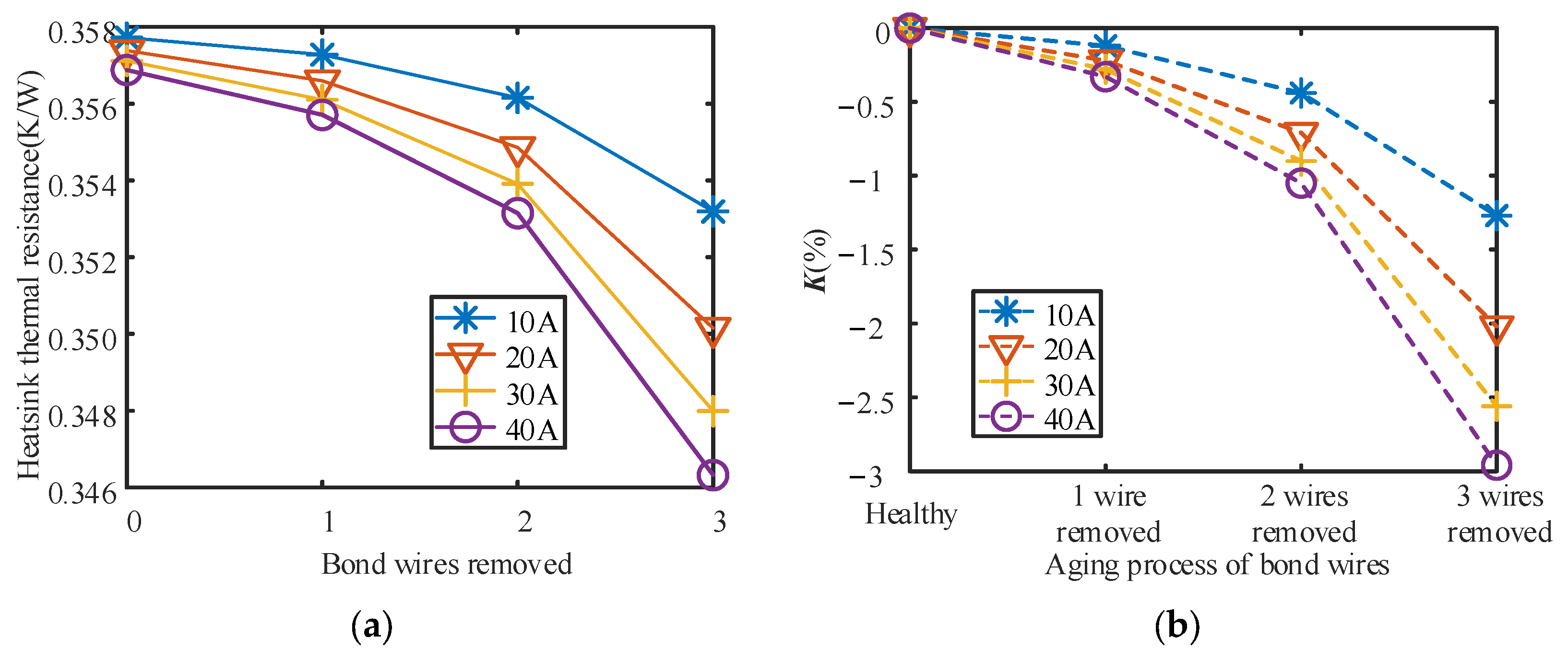
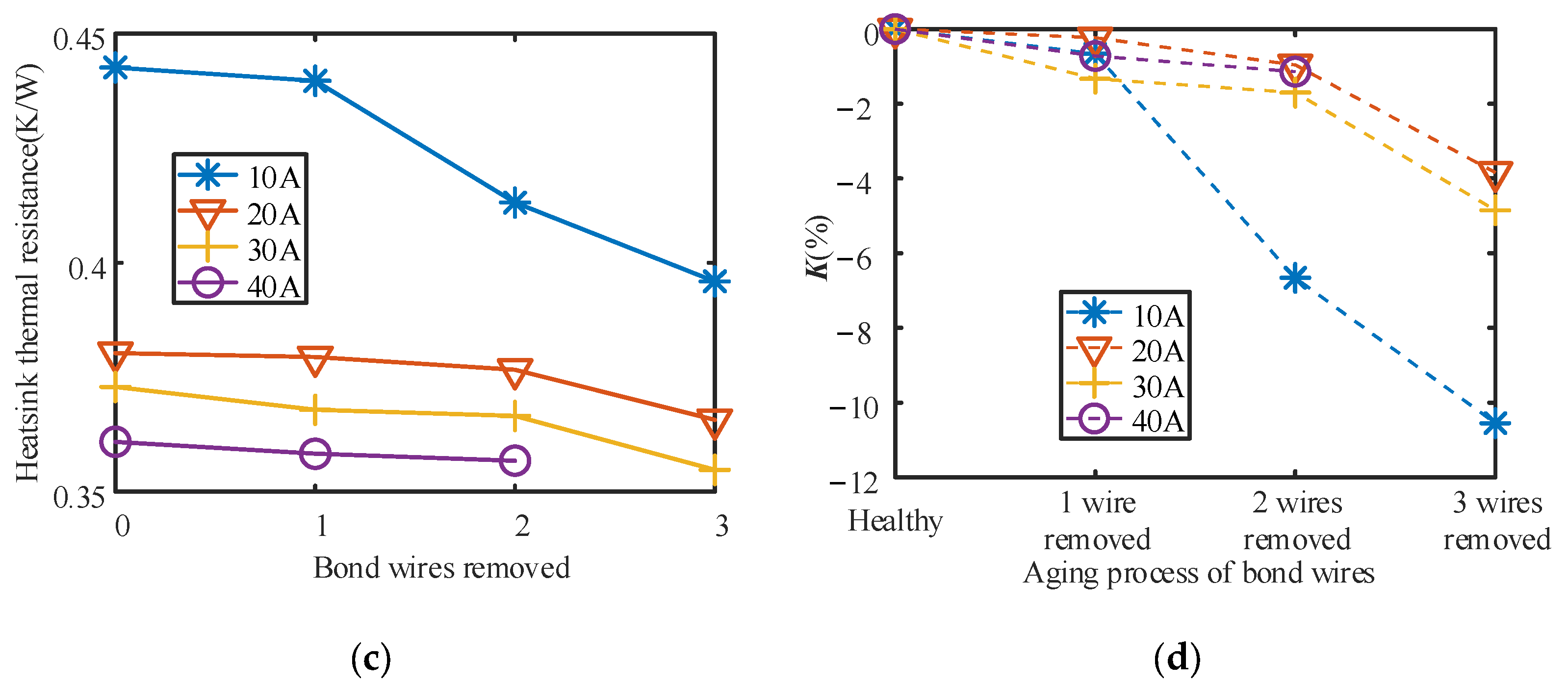
| 10 A | 1.71% | 2.31% | 3.49% | 6.59% |
| 20 A | 2.83% | 3.82% | 5.72% | 10.59% |
| 30 A | 3.65% | 4.91% | 7.31% | 13.34% |
| 40 A | 4.30% | 5.77% | 8.55% | 15.42% |
| Detection Type | Measured Parameter | Working Conditions | Reference | |
|---|---|---|---|---|
| Invasive Detection Method | Added layout | Voltage | Normal condition | [8] |
| Current sensor | Current | Normal condition | [9,10,11] | |
| Non-Invasive Detection Method | Gate charging current | Gate signal | Normal condition | [12] |
| Gate charging time | Gate signal | Special gate driver | [13] | |
| Transconductance | Gate signal | Normal condition | [14] | |
| Stray inductance | Gate signal | Normal condition | [15] | |
| Conduct voltage at the inflected point with special gate voltage | Conduct voltage | Special conduct current at a special gate voltage | [17,18,19] | |
| Short-circuit current with special gate voltage | Current | Short-circuit at a special gate voltage | [20] | |
| Measured thermal resistance of heatsink | Thermal resistance | Normal condition | This paper | |
Publisher’s Note: MDPI stays neutral with regard to jurisdictional claims in published maps and institutional affiliations. |
© 2022 by the authors. Licensee MDPI, Basel, Switzerland. This article is an open access article distributed under the terms and conditions of the Creative Commons Attribution (CC BY) license (https://creativecommons.org/licenses/by/4.0/).
Share and Cite
Luo, D.; Chen, M.; Lai, W.; Xia, H.; Deng, Z.; Wang, Z.; Yu, K. A Fault Detection Method of IGBT Bond Wire Fatigue Based on the Reduction of Measured Heatsink Thermal Resistance. Electronics 2022, 11, 1021. https://doi.org/10.3390/electronics11071021
Luo D, Chen M, Lai W, Xia H, Deng Z, Wang Z, Yu K. A Fault Detection Method of IGBT Bond Wire Fatigue Based on the Reduction of Measured Heatsink Thermal Resistance. Electronics. 2022; 11(7):1021. https://doi.org/10.3390/electronics11071021
Chicago/Turabian StyleLuo, Dan, Minyou Chen, Wei Lai, Hongjian Xia, Zhenyu Deng, Zhi Wang, and Kai Yu. 2022. "A Fault Detection Method of IGBT Bond Wire Fatigue Based on the Reduction of Measured Heatsink Thermal Resistance" Electronics 11, no. 7: 1021. https://doi.org/10.3390/electronics11071021