
A Comprehensive Virtual Synchronous Generator Control Strategy for Harmonic and Imbalance Voltage Suppression of Multi-Inverter Parallel Microgrid


Abstract
:1. Introduction
- (1)
- Propose a harmonic and voltage imbalance suppression comprehensive strategy for distributed control of a multi-inverter parallel microgrid. This comprehensive strategy has an inertia section, which improves the lack of inertia in the traditional control method. Apart from improving the power quality of the microgrid, the secondary adjustment of the frequency is realized by the distributed control strategy.
- (2)
- A small-signal state-space-based model is introduced for certain harmonics suppression to analyze non-linear load-induced system output characteristics caused by the superposition of fundamental and high-order harmonic components.
- (3)
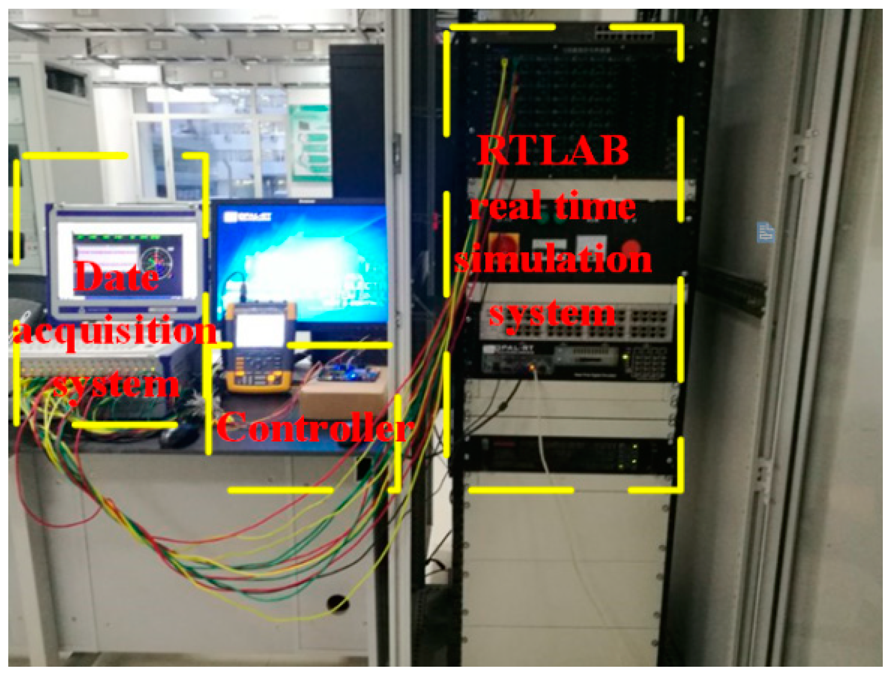
- To verify the validity of the proposed method, an accuracy model by the RTLAB semi-physical simulation system, the microgrid simulation is conducted.
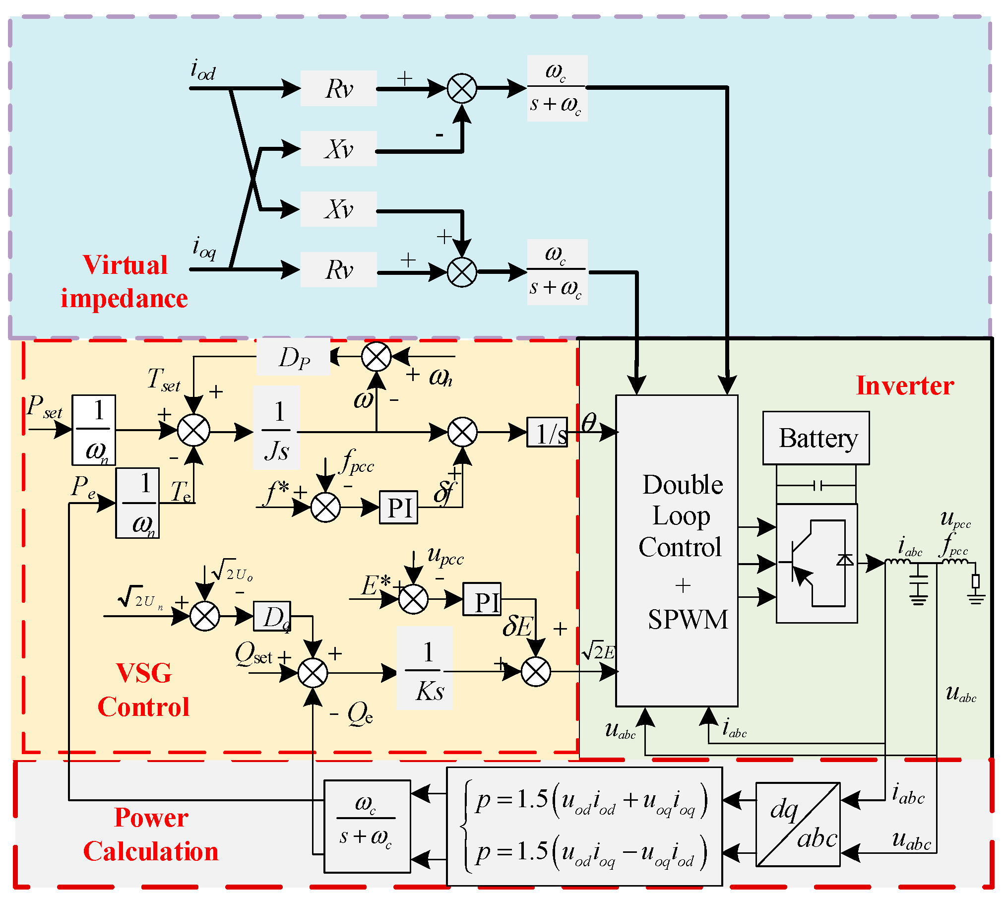
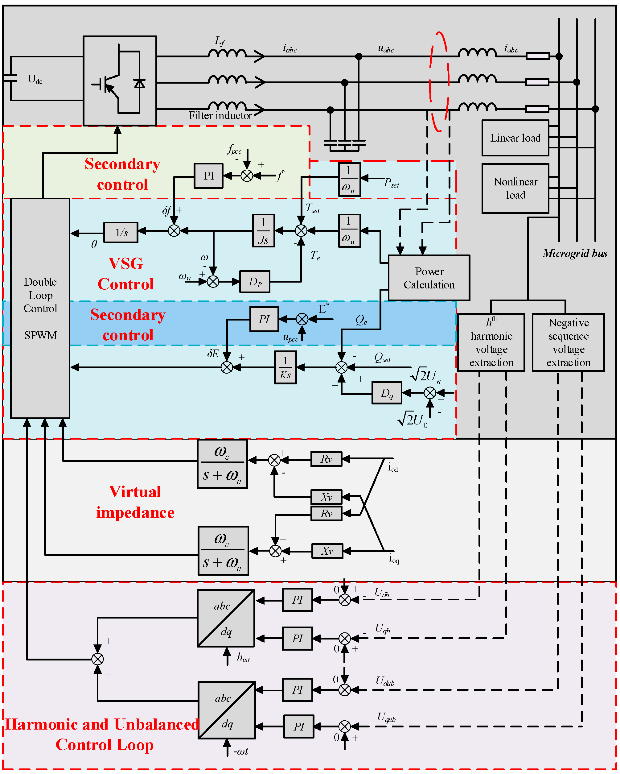
2. A Hierarchical VSG Secondary Control Strategy Based on Harmonic and Imbalance Principle
2.1. The Strategy and Modelling Based on Harmonic Imbalance Principle
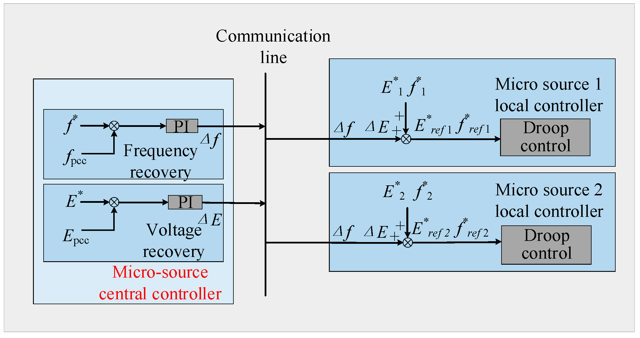
2.2. The Secondary Control Strategy and Modelling
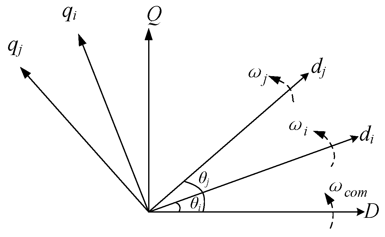
3. Small-Signal Model for Parallel-Based VSG Control Operation of Multi-Inverter Microgrid
3.1. Small-Signal Model for Parallel based VSG Control
3.1.1. VSG Power Loop Model Modeling
3.1.2. Virtual Impedance Modelling
3.1.3. Voltage and Current Loops Modeling
3.1.4. LC Filter Modeling
3.1.5. Small-Signal Model for VSG Inverter
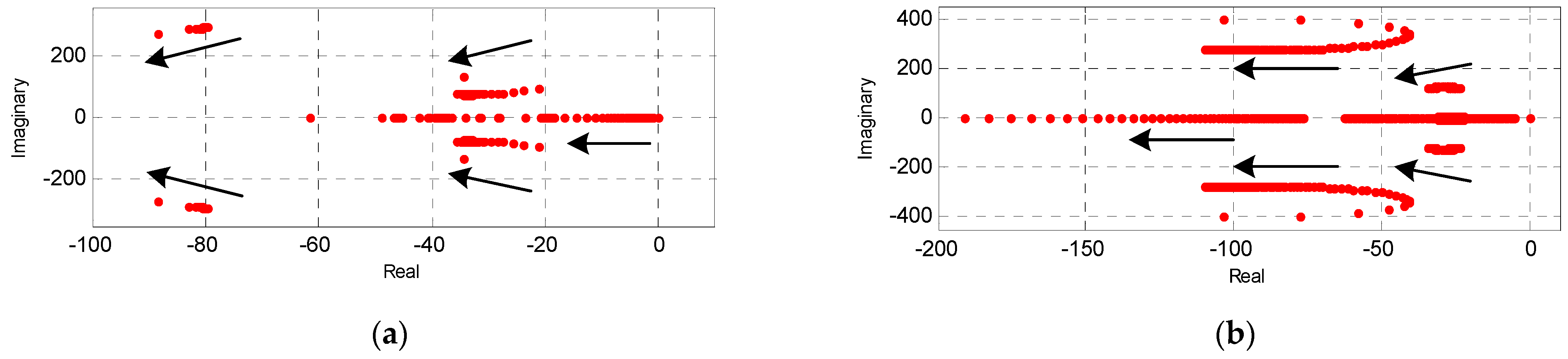
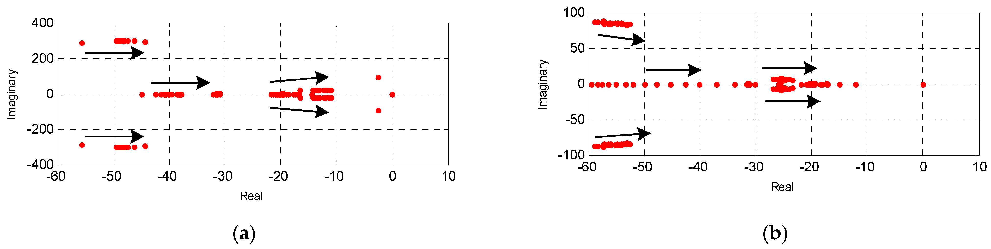
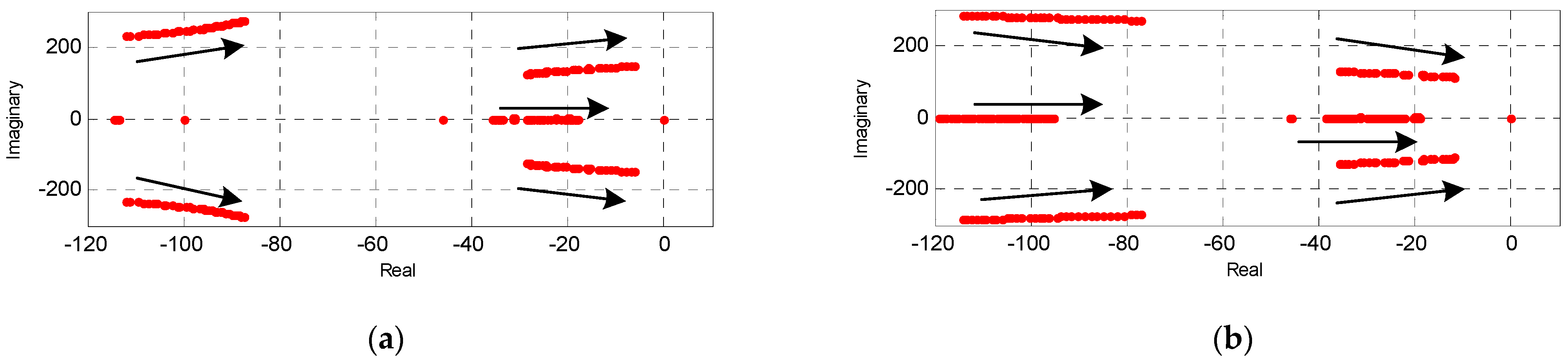
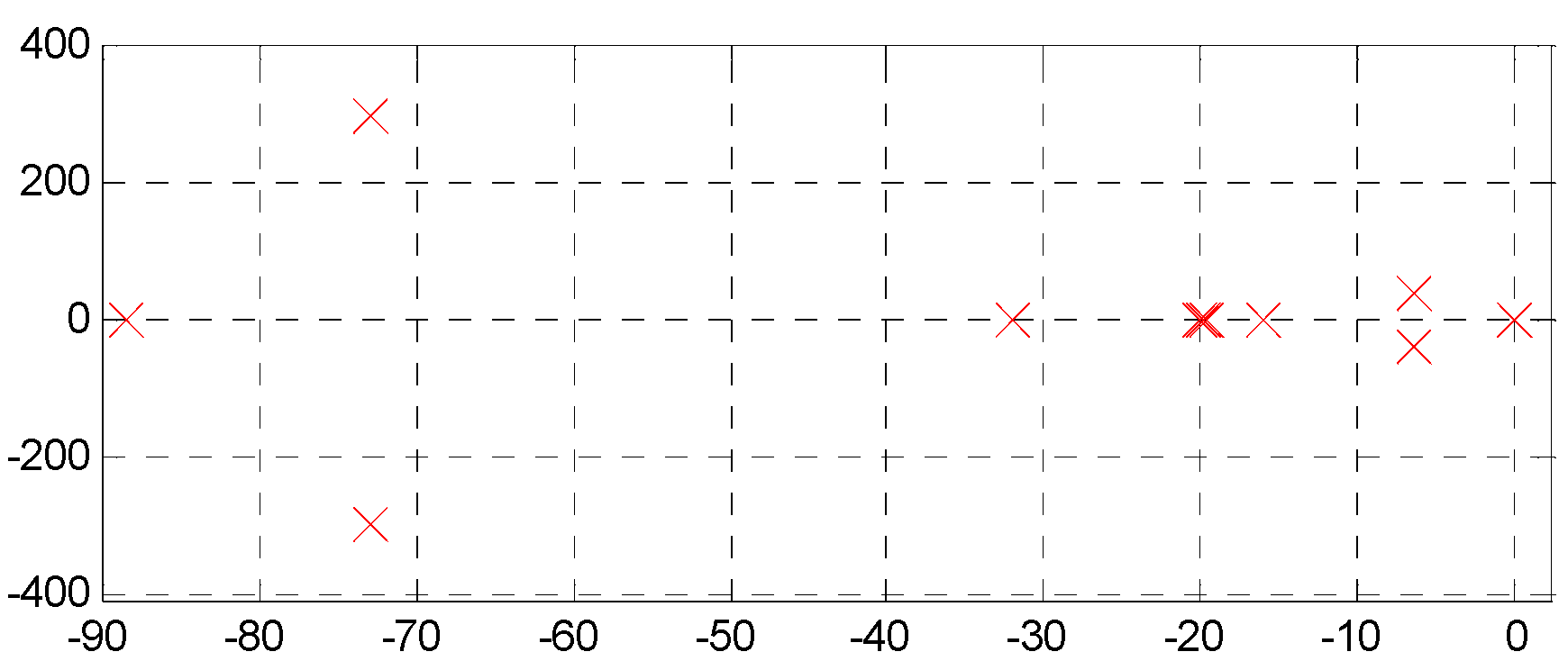
3.2. The Root Locus of the Parallel Based VSG Control
4. Experiment Results
5. Conclusions
Author Contributions
Funding
Conflicts of Interest
References
- Mehigan, L.; Deane, J.P.; Gallachóir, B.Ó.; Bertsch, V. A review of the role of distributed generation (DG) in future electricity systems. Energy 2018, 163, 822–836. [Google Scholar] [CrossRef]
- Ahmad, S.; Mekhilef, S.; Mokhlis, H.; Karimi, M.; Pourdaryaei, A.; Ahmed, T.; Jhuma, U.K.; Afzal, S. Fuzzy Logic-Based Direct Power Control Method for PV Inverter of Grid-Tied AC Microgrid without Phase-Locked Loop. Electronics 2021, 10, 3095. [Google Scholar] [CrossRef]
- Ghanbari, A.R.; Karimi, H.R.; Jadid, S. Optimal planning and operation of multi-carrier networked microgrids considering multi-energy hubs in distribution networks. Energy 2020, 204, 117936. [Google Scholar] [CrossRef]
- Peng, Y.; Shuai, Z.; Liu, X.; Li, Z.; Guerrero, J.M.; Shen, Z.J. Modeling and stability analysis of inverter-based microgrid under harmonic conditions. IEEE Trans. Smart Grid 2019, 11, 1330–1342. [Google Scholar] [CrossRef]
- Burgos-Mellado, C.; Llanos, J.; Cárdenas, R.; Sáez, D.; Olivares, D.E.; Sumner, M.; Costabeber, A. Distributed control strategy based on a consensus algorithm and on the conservative power theory for imbalance and harmonic sharing in 4-wire microgrids. IEEE Trans. Smart Grid 2020, 11, 1604–1619. [Google Scholar] [CrossRef]
- Bevrani, H.; Ise, T.; Miura, Y. Virtual synchronous generators: A survey and new perspectives. Int. J. Electr. Power Energy Syst. 2014, 54, 244–254. [Google Scholar] [CrossRef]
- Liu, J.; Miura, Y.; Bevrani, H.; Ise, T. Enhanced virtual synchronous generator control for parallel inverters in microgrids. IEEE Trans. Smart Grid 2017, 8, 2268–2277. [Google Scholar] [CrossRef]
- Yan, X.; Wang, C.; Wang, Z.; Ma, H.; Liang, B.; Wei, X. A United Control Strategy of Photovoltaic-Battery Energy Storage System Based on Voltage-Frequency Controlled VSG. Electronics 2021, 10, 2047. [Google Scholar] [CrossRef]
- Hirase, Y.; Abe, K.; Sugimoto, K.; Sakimoto, K.; Bevrani, H.; Ise, T. A novel control approach for virtual synchronous generators to suppress frequency and voltage fluctuations in Micro-grids. Appl. Energy 2017, 210, 699–710. [Google Scholar] [CrossRef]
- Yang, L.; Ma, J.; Wang, S.; Liu, T.; Wu, Z.; Wang, R.; Tang, L. The Strategy of Active Grid Frequency Support for Virtual Synchronous Generator. Electronics 2021, 10, 1131. [Google Scholar] [CrossRef]
- Liu, J.; Miura, Y.; Ise, T. Comparison of Dynamic Characteristics Between Virtual Synchronous Generator and Droop Control in Inverter-Based Distributed Generators. IEEE Trans. Power Electron. 2015, 31, 3600–3611. [Google Scholar] [CrossRef]
- Du, Y.; Guerrero, J.M.; Chang, L.; Su, J.; Mao, M. Modeling, analysis, and design of a frequency-droop-based virtual synchronous generator for microgrid applications. In Proceedings of the 2013 IEEE ECCE Asia Downunder, Melbourne, Australia, 3–6 June 2013; pp. 643–649. [Google Scholar] [CrossRef] [Green Version]
- Jiang, K.; Su, H.; Lin, H.; He, K.; Zeng, H.; Che, Y. A Practical Secondary Frequency Control Strategy for Virtual Synchronous Generator. IEEE Trans. Smart Grid 2020, 11, 2734–2736. [Google Scholar] [CrossRef]
- Torres, M.; Lopes, L.A. A virtual synchronous machine to support dynamic frequency control in a mini-grid that operates in frequency droop mode. Energy Power Eng. 2013, 5, 259–265. [Google Scholar] [CrossRef] [Green Version]
- Zhang, B.; Yan, X.; Huang, Y.; Liu, Z.; Xiao, X. Stability control and inertia matching method of multi-parallel virtual synchronous generators. Trans. China Electrotech. Soc. 2017, 32, 42–52. [Google Scholar]
- Li, Y.; Gao, W.; Yan, W.; Huang, S.; Wang, R.; Gevorgian, V.; Gao, D. Data-driven Optimal Control Strategy for Virtual Synchronous Generator via Deep Reinforcement Learning Approach. J. Mod. Power Syst. Clean Energy 2021, 4, 919–929. [Google Scholar] [CrossRef]
- Elbasuony, G.S.; Aleem, S.A.; Ibrahim, A.; Sharaf, A.M. A unified index for power quality evaluation in distributed generation systems. Energy 2018, 149, 607–622. [Google Scholar] [CrossRef]
- Delfino, F.; Rossi, M.; Ferro, G.; Minciardi, R.; Robba, M. MPC-based tertiary and secondary optimal control in islanded microgrids. In Proceedings of the 2015 IEEE International Symposium on Systems Engineering (ISSE), Rome, Italy, 28–30 September 2015; pp. 23–28. [Google Scholar] [CrossRef]
- Soni, N.; Doolla, S.; Chandorkar, M. Improvement of Transient Response in Microgrids Using Virtual Inertia. IEEE Trans. Power Deliv. 2013, 28, 1830–1838. [Google Scholar] [CrossRef]
- Rosini, A.; Mestriner, D.; Labella, A.; Bonfiglio, A.; Procopio, R. A decentralized approach for frequency and voltage regulation in islanded PV-Storage microgrids. Electr. Power Syst. Res. 2021, 193, 106974. [Google Scholar] [CrossRef]
- Ferro, G.; Robba, M.; Sacile, R. A Model Predictive Control Strategy for Distribution Grids: Voltage and Frequency Regulation for Islanded Mode Operation. Energies 2020, 13, 2637. [Google Scholar] [CrossRef]
- Grzegorz, B.; Marian, P. Power Theories for Improved Power Quality; China Machine Press: Beijing, China, 2014. [Google Scholar]
- Liu, Z.; Xu, X.; Makram, E. Harmonics assessment and mitigation: A case study on an unbalanced stand-alone microgrid integrated with PV. In Proceedings of the 2015 North American Power Symposium (NAPS), Charlotte, NC, USA, 4–6 October 2015; pp. 1–6. [Google Scholar] [CrossRef]
- Dong, Y.; Han, Z.; Mu, Y.; Dong, H.; Ma, S.; Cai, Z. Research on micro-grid harmonic suppression controlstrategy based on synchronous inverter technology. Renew. Energy Resources 2020, 38, 1670–1678. [Google Scholar] [CrossRef]
- Zhong, Q. Control of Power Inverters in Renewable Energy and Smart Grid Integration; China Machine Press: Beijing, China, 2016. [Google Scholar]
- Choudhury, S.R.; Das, A.; Anand, S.; Tungare, S.; Sonawane, Y.D. Adaptive shunt filtering control of UPQC for increased nonlinear loads. IET Power Electron. 2018, 12, 330–336. [Google Scholar] [CrossRef]
- Lee, T.; Lee, C.; Cheng, P. An Autonomous Harmonic Filtering Strategy for Distributed Energy Resources Converters in Micro-grid. In Proceedings of the Power Electronics Conference, Bonito-Mato Grosso do Sul, Brazil, 27 September–1 October 2009; pp. 19–25. [Google Scholar] [CrossRef]
- Lee, T.; Cheng, P. Design of a New Cooperative Harmonic Filtering Strategy for Distributed Generation Interface Converters in an Islanding Network. IEEE Trans. Power Electron. 2007, 22, 1919–1927. [Google Scholar] [CrossRef]
- Shi, R.; Zhang, X.; Liu, F.; Xu, H. A control strategy for unbalanced and nonlinear mixed loads of virtual synchronous generators. Proc. CSEE 2016, 36, 6086–6095. [Google Scholar] [CrossRef]
- Zhou, J.; Kim, S.; Zhang, H.; Sun, Q.; Han, R. Consensus-Based Distributed Control for Accurate Reactive, Harmonic, and Imbalance Power Sharing in Microgrids. IEEE Trans. Smart Grid 2016, 9, 2453–2467. [Google Scholar] [CrossRef] [Green Version]
- Yin, X.; Lin, Y.; Li, W.; Gu, Y.; Liu, H.; Lei, P. A novel fuzzy integral sliding mode current control strategy for maximizing wind power extraction and eliminating voltage harmonics. Energy 2015, 85, 677–686. [Google Scholar] [CrossRef]
- Dong, H.; Yuan, S.; Han, Z.; Zhiyuan, C.; Jia, G.; Yangyang, G. A comprehensive strategy for accurate reactive power distribution, stability improvement, and harmonic suppression of multi-inverter-based micro-grid. Energies 2018, 11, 745. [Google Scholar] [CrossRef] [Green Version]
- Li, M.; Huang, W.; Tai, N.; Yang, L.; Duan, D.; Ma, Z. A dual-adaptivity inertia control strategy for virtual synchronous generator. IEEE Trans. Power Syst. 2020, 35, 594–604. [Google Scholar] [CrossRef]
- Cheema, K.M. A comprehensive review of virtual synchronous generator. Int. J. Electr. Power Energy Syst. 2020, 120, 106006. [Google Scholar] [CrossRef]
- Wodyk, S.; Iwanski, G. Three-phase converter power control under grid imbalance with consideration of instantaneous power components limitation. Int. Trans. Electr. Energy Syst. 2020, 30, 12389. [Google Scholar] [CrossRef]
- Brandão, D.I.; Ferreira, W.M.; Alonso, A.M.; Tedeschi, E.; Marafão, F.P. Optimal Multiobjective Control of Low-Voltage AC Microgrids: Power Flow Regulation and Compensation of Reactive Power and Unbalance. IEEE Trans. Smart Grid 2020, 11, 1239–1252. [Google Scholar] [CrossRef] [Green Version]
- Leitner, S.; Yazdanian, M.; Mehrizi-Sani, A.; Muetze, A. Small-signal stability analysis of an inverter-based micro-grid with internal model–based controllers. IEEE Trans. Smart Grid 2017, 99, 1–10. [Google Scholar] [CrossRef]
- Li, Z.; Shahidehpour, M. Small-Signal Modeling and Stability Analysis of Hybrid AC/DC Microgrids. IEEE Trans. Smart Grid 2019, 10, 2080–2095. [Google Scholar] [CrossRef]


| System Parameters | Symbol | Numerical Value | System Parameters | Symbol | Numerical Value |
|---|---|---|---|---|---|
| Filter inductor | Lf | 0.6 × 10⁻³ H | VSG Inertia coefficient | J | 0.2 |
| Filter parasitic resistance | Rf | 1 × 10⁻² Ω | VSG excitation coefficient | K | 7 |
| Filter capacitor | Cf | 0 | Active droop coefficient | mp | 15 |
| DC bus voltage | Udc | 700 V | Reactive droop coefficient | nq | 2000 |
| Line resistance | Lline | 2.8 × 10⁻³ H | Voltage loop control proportional coefficient | Kup | 10 |
| Line inductance | Rline | 4.28 × 10⁻² Ω | Voltage loop control integral coefficient | Kui | 100 |
| VSG1 Virtual resistance | Rv1 | 0 Ω | Current loop control proportional coefficient | Kip | 5 |
| VSG2 Virtual resistance | Rv2 | 0 Ω | Harmonic suppression loop proportional coefficient | Khup | 10 |
| VSG1 Virtual reactance | Lv1 | 0.01 H | Harmonic suppression loop integral coefficient | Khui | 50 |
| VSG2 Virtual reactance | Lv2 | 0.01 H | imbalance suppression loop proportional coefficient | Khup | 3 |
| VSG Rated frequency | f* | 50 Hz | imbalance suppression loop integral coefficient | Khui | 2 |
| VSG Rated voltage | E* | 311 V |
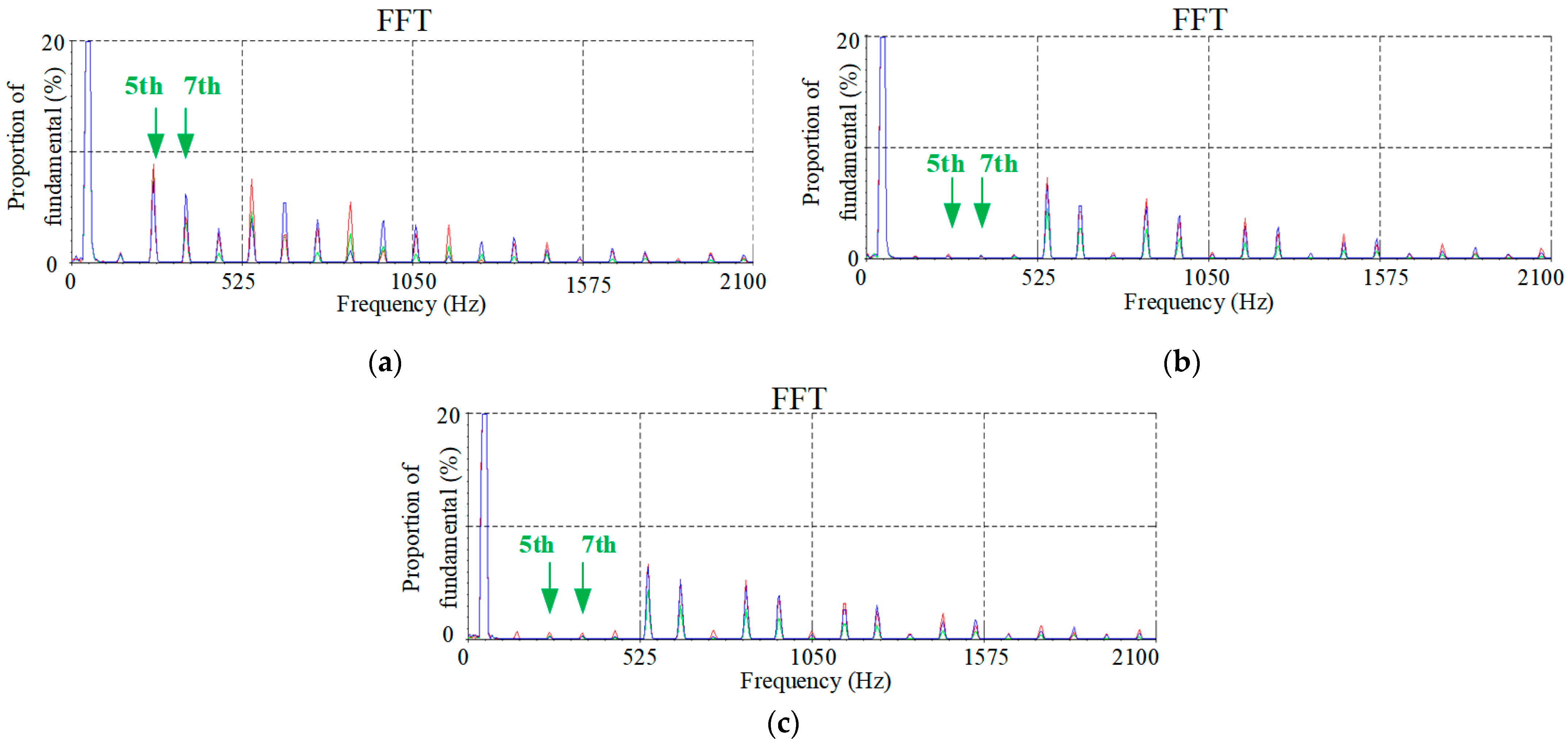
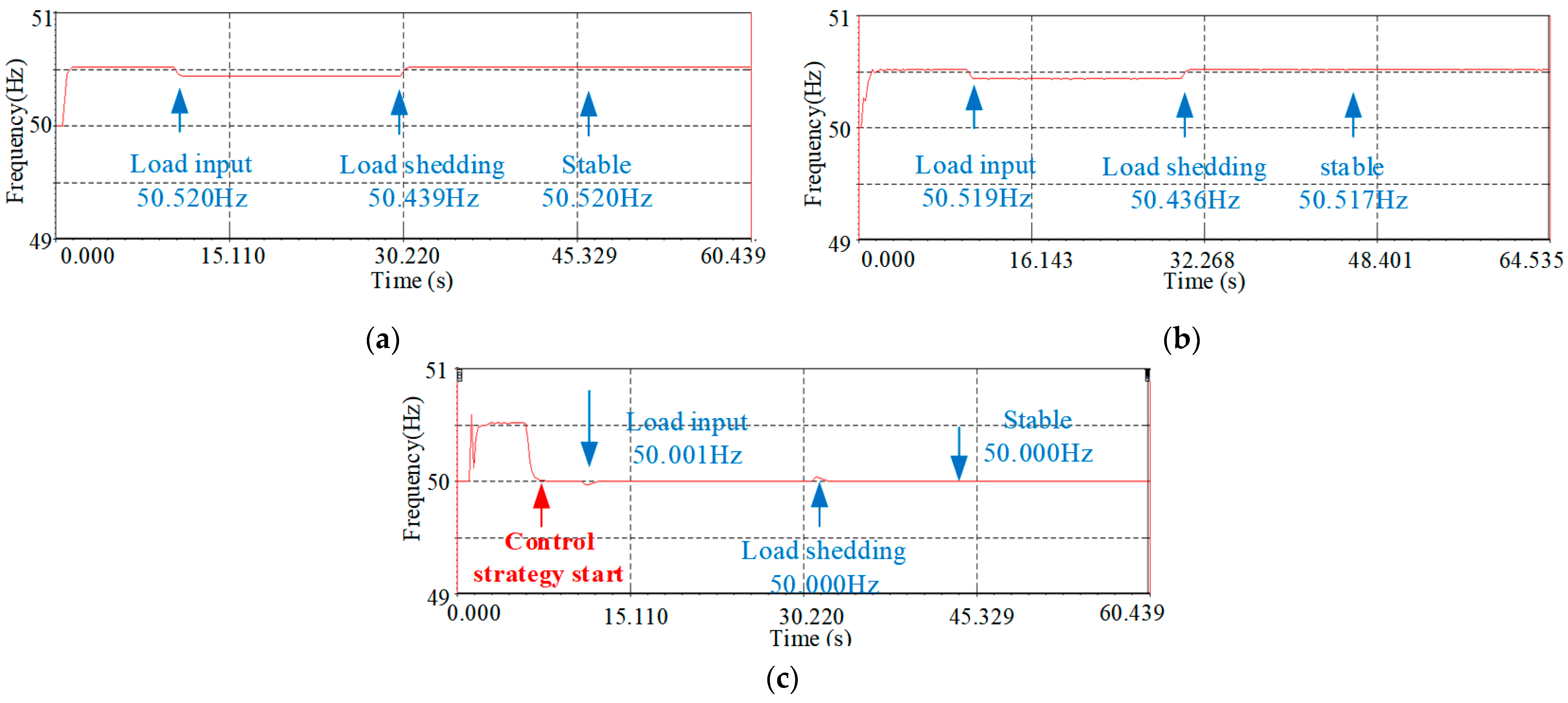
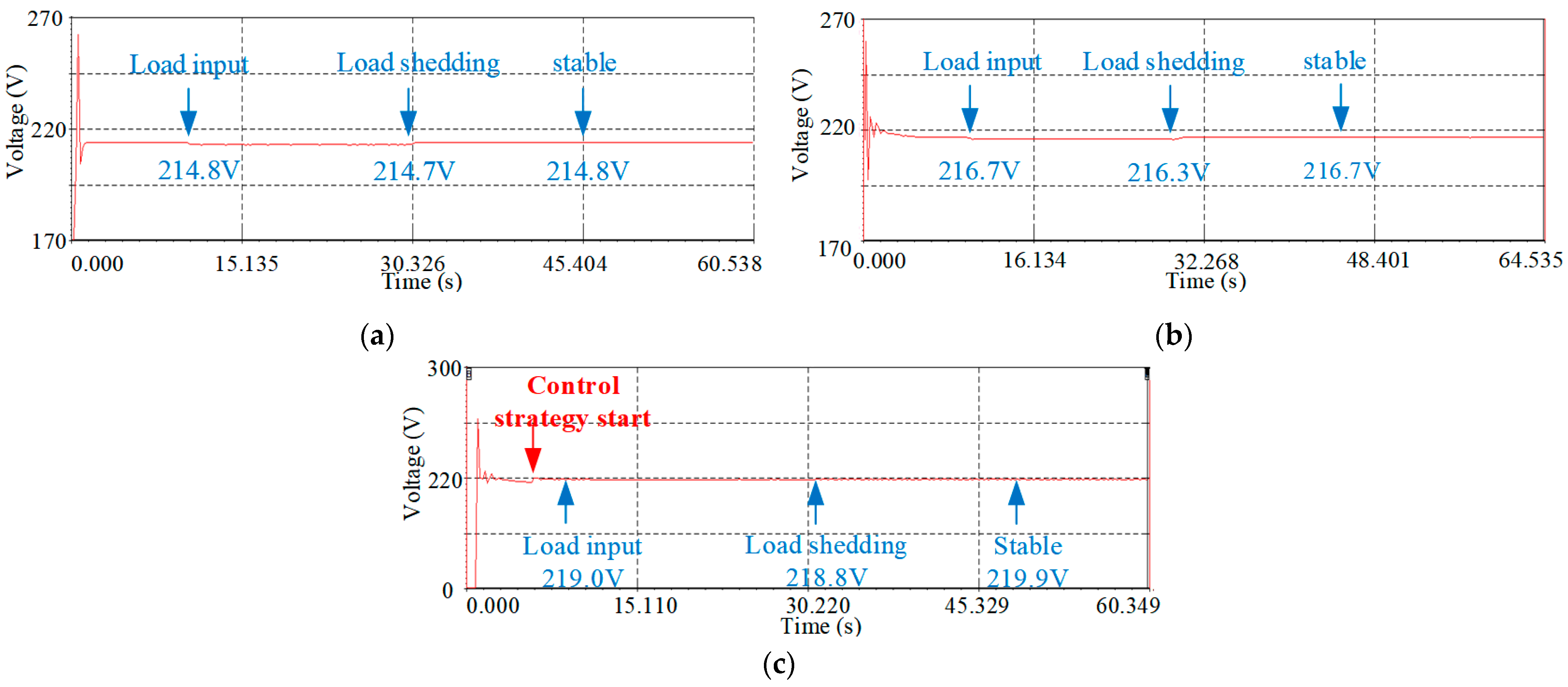
| Control Strategy | THD of Voltage Harmonics (%) | Imbalance Ratio of Voltage (%) | Frequency (Hz) | RMS of Voltage (V) | Inertia and Damping (YES/NO) | |
|---|---|---|---|---|---|---|
| 5th | 7th | |||||
| PI control strategy | 7.1 | 4.6 | 5.61 | 50.52 | 214.8 | NO |
| Comprehensive droop control strategy | 0.08 | 0.13 | 0.05 | 50.00 | 220 | NO |
| Harmonic and imbalance voltage suppression of multi-inverter parallel VSG | 0.12 | 0.08 | 0.1 | 50.52 | 216.7 | YES |
| Multi-inverter parallel VSG adding a secondary control strategy | 0.11 | 0.08 | 0 | 50.00 | 219.9 | YES |
Publisher’s Note: MDPI stays neutral with regard to jurisdictional claims in published maps and institutional affiliations. |
© 2022 by the authors. Licensee MDPI, Basel, Switzerland. This article is an open access article distributed under the terms and conditions of the Creative Commons Attribution (CC BY) license (https://creativecommons.org/licenses/by/4.0/).
Share and Cite
Dong, Y.; Ma, S.; Han, Z.; Dong, H.; Li, X. A Comprehensive Virtual Synchronous Generator Control Strategy for Harmonic and Imbalance Voltage Suppression of Multi-Inverter Parallel Microgrid. Electronics 2022, 11, 492. https://doi.org/10.3390/electronics11030492
Dong Y, Ma S, Han Z, Dong H, Li X. A Comprehensive Virtual Synchronous Generator Control Strategy for Harmonic and Imbalance Voltage Suppression of Multi-Inverter Parallel Microgrid. Electronics. 2022; 11(3):492. https://doi.org/10.3390/electronics11030492
Chicago/Turabian StyleDong, Yannan, Shaohua Ma, Zijiao Han, Henan Dong, and Xiangjun Li. 2022. "A Comprehensive Virtual Synchronous Generator Control Strategy for Harmonic and Imbalance Voltage Suppression of Multi-Inverter Parallel Microgrid" Electronics 11, no. 3: 492. https://doi.org/10.3390/electronics11030492