
Digital Pole Control for Speed and Torque Variation in an Axial Flux Motor with Permanent Magnets


Abstract
:1. Introduction
2. Methods
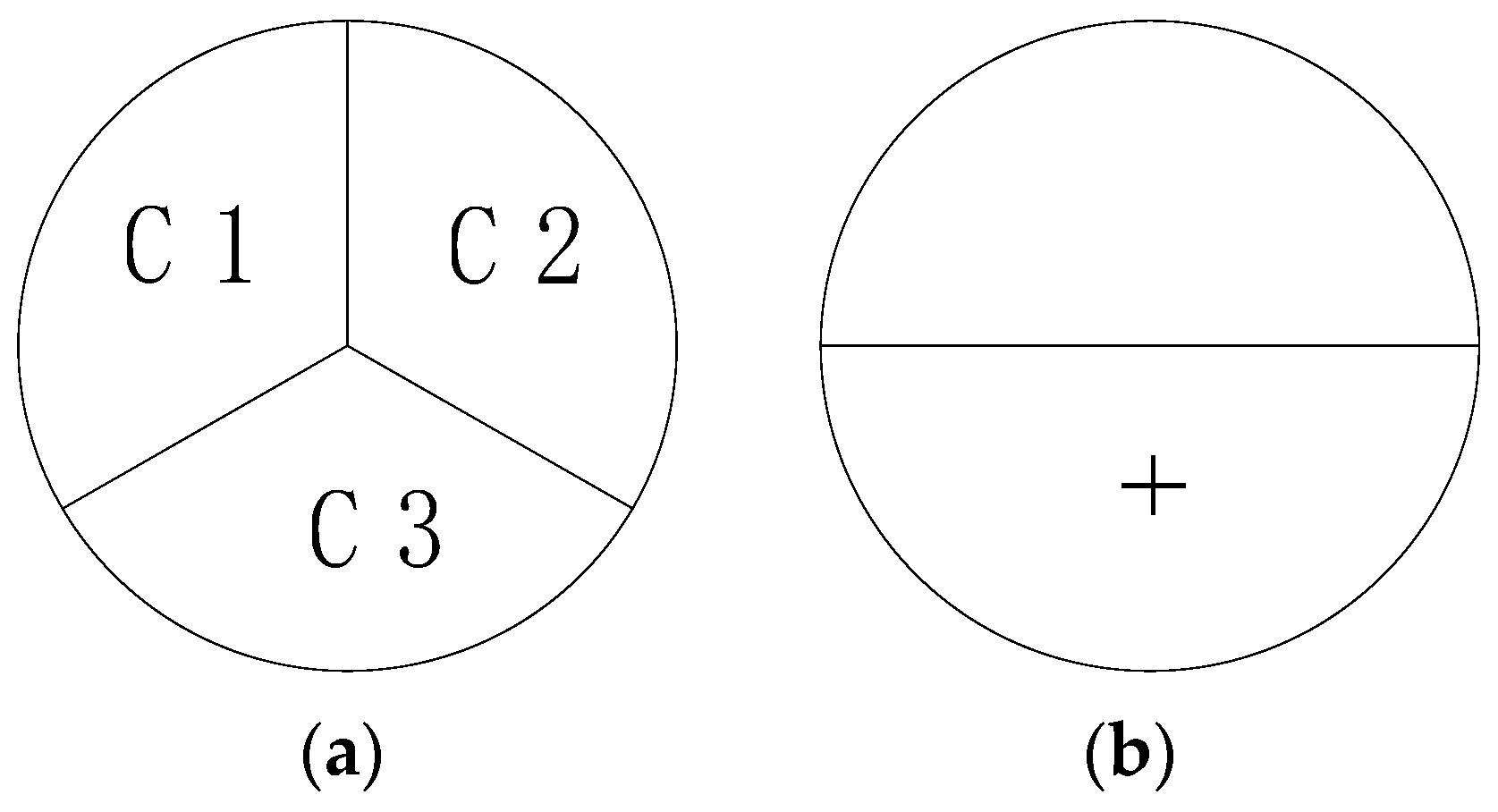
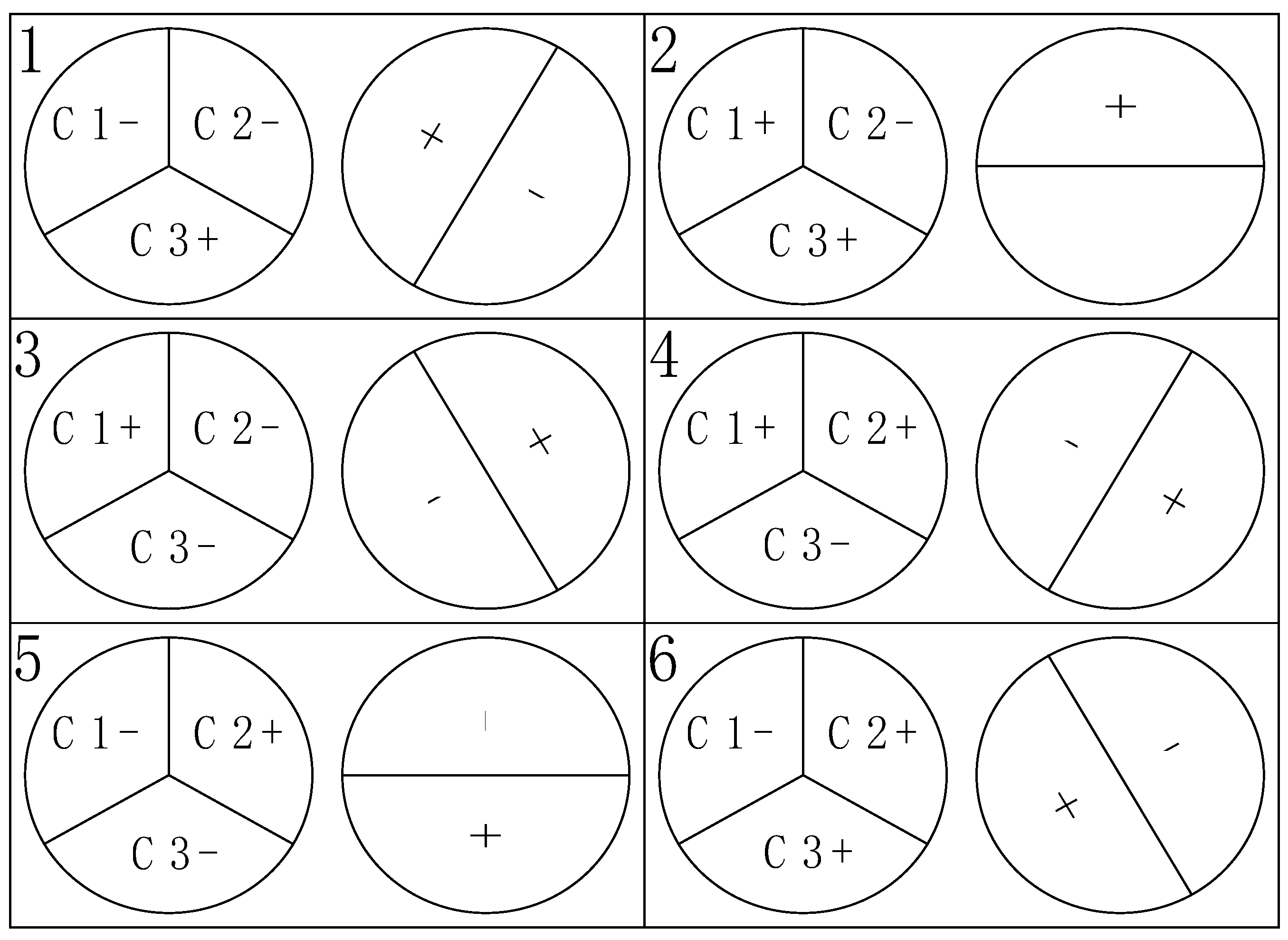
2.1. Control Theory
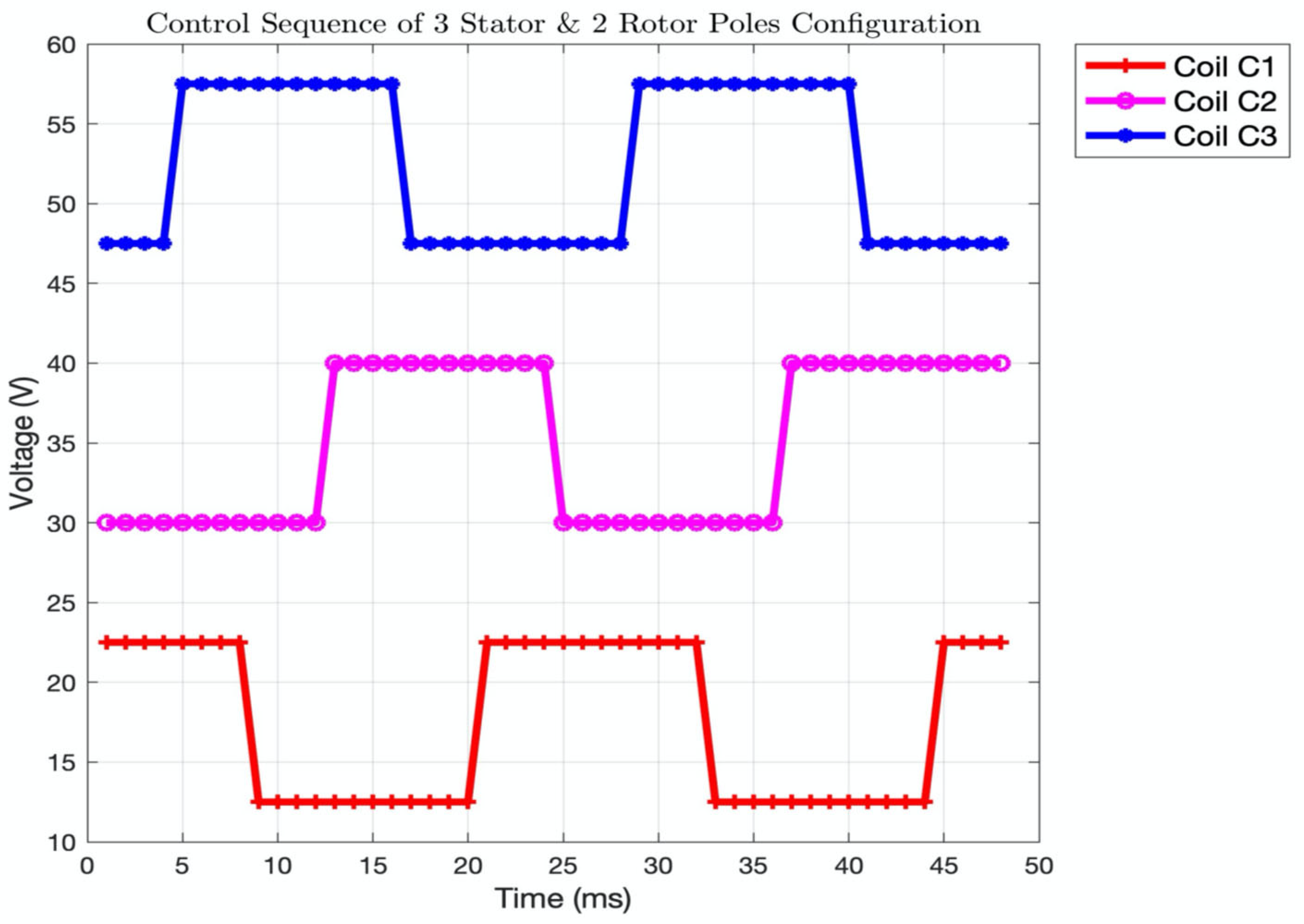
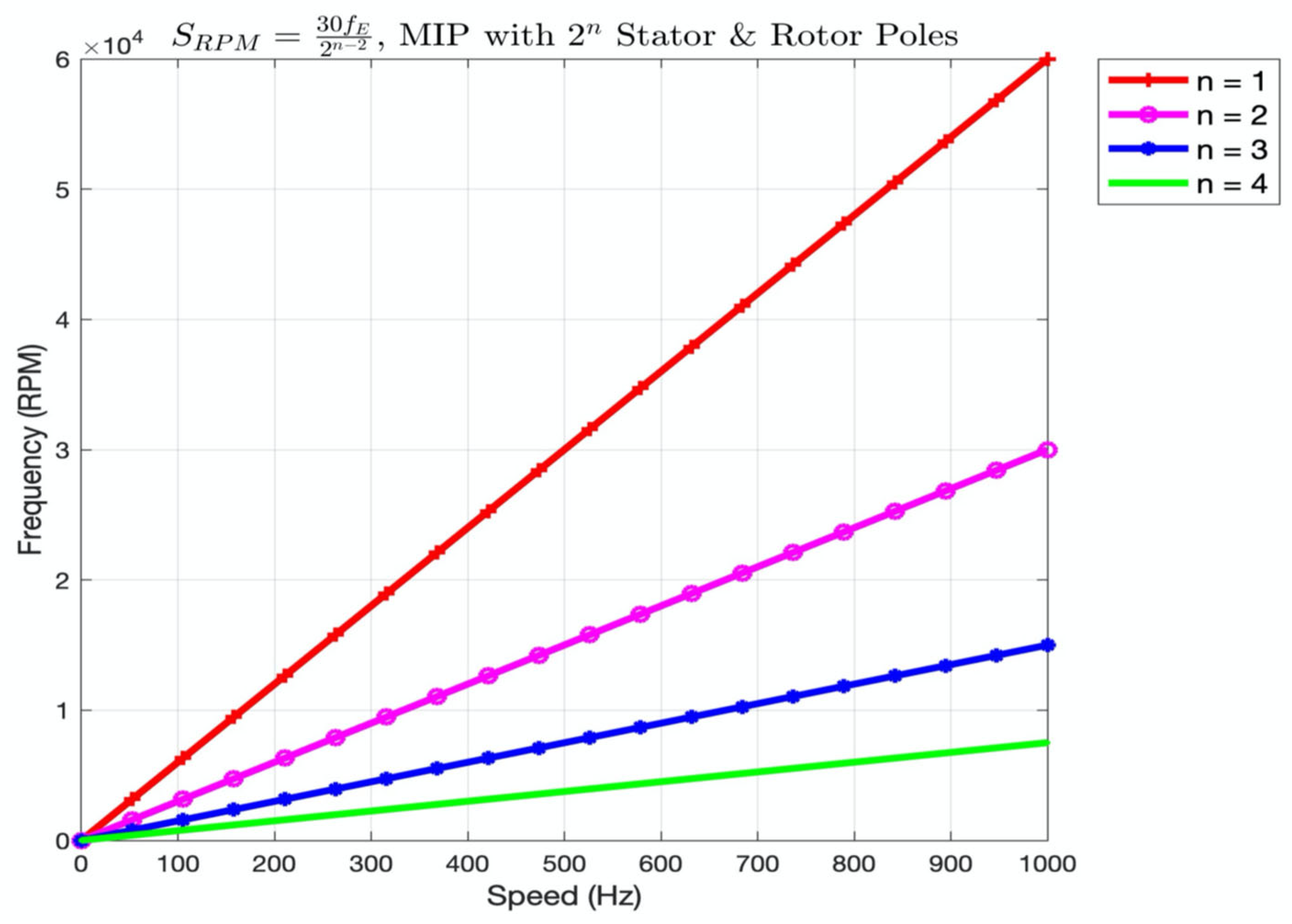
2.2. Speed Control for 3n Stator and 2n Rotor Configuration
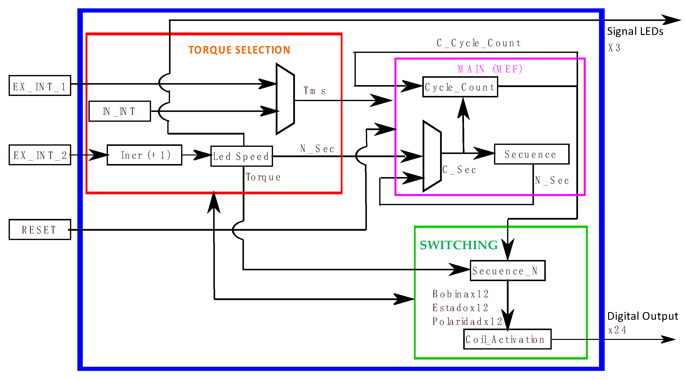
2.3. Speed and Torque Control Implementation
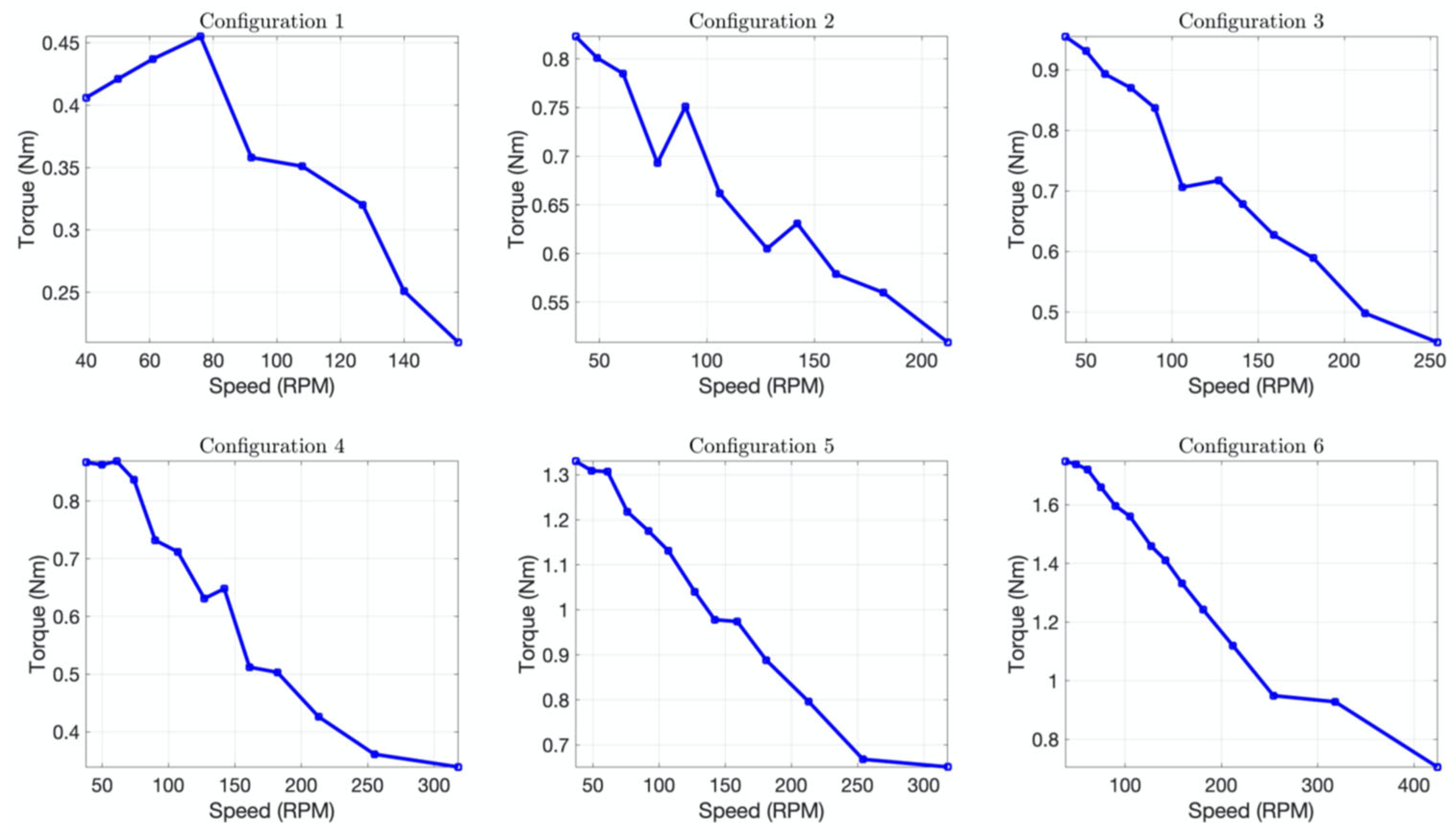
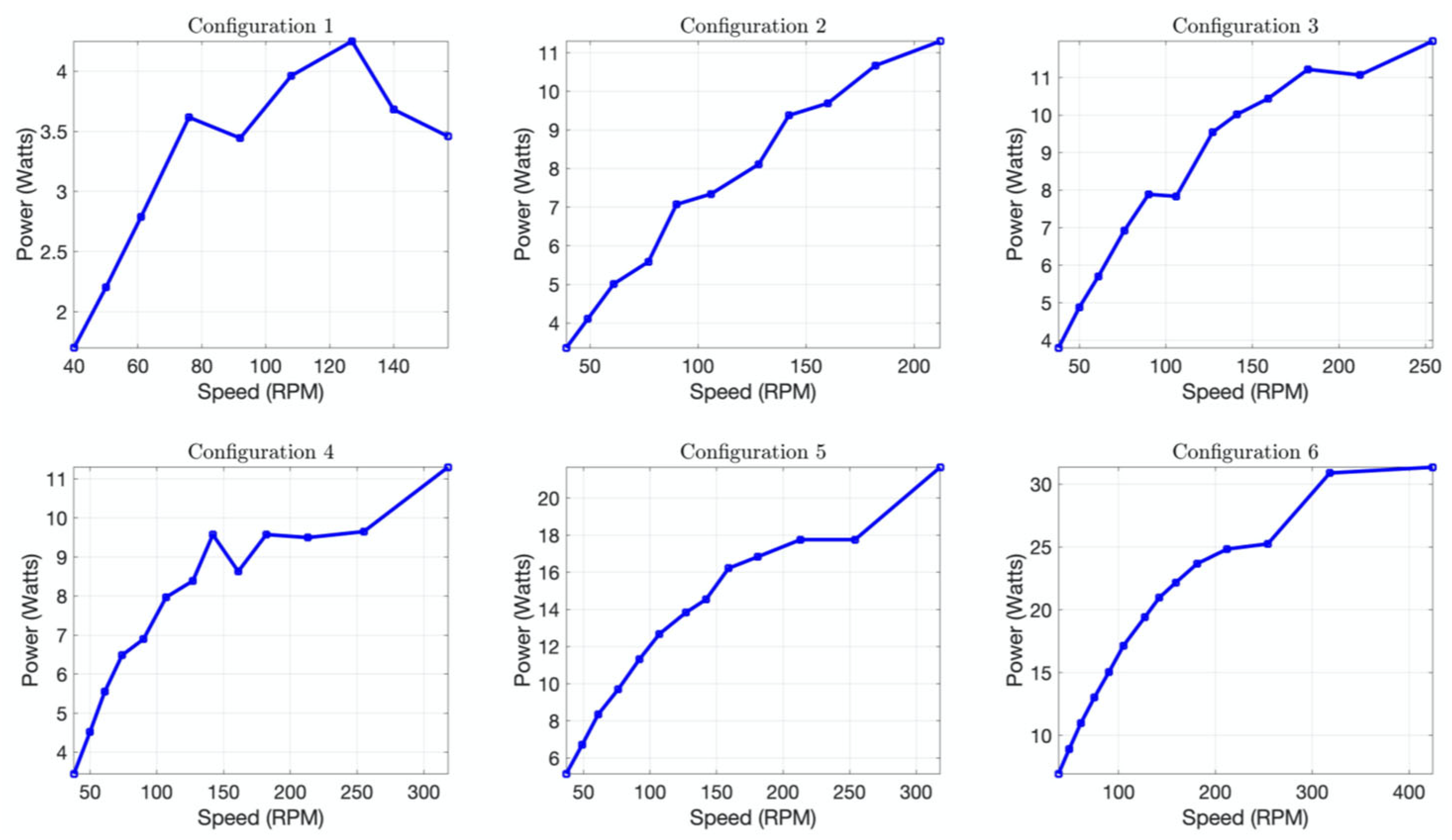
3. Results
4. Conclusions
Author Contributions
Funding
Informed Consent Statement
Acknowledgments
Conflicts of Interest
References
- Lambert, T.; Biglarbegian, M.; Mahmud, S. A Novel Approach to the Design of Axial-Flux Switched-Reluctance Motors. Machines 2015, 3, 27–54. [Google Scholar] [CrossRef]
- Rahman, K.; Fahimi, B.; Suresh, G.; Rajarathnam, A.; Ehsani, M. Advantages of switched reluctance motor applications to EV and HEV: Design and control issues. IEEE Trans. Ind. Appl. 2000, 36, 111–121. [Google Scholar] [CrossRef]
- Abdullah, H.; Ramasamy, G.; Ramar, K.; Aravind, C.V. Design consideration of dual axial flux motor for electric vehicle applications. In Proceedings of the 2015 IEEE Conference on Energy Conversion (CENCON), Johor Bahru, Malaysia, 19–20 October 2015; pp. 72–77. [Google Scholar]
- Madhavan, R.; Fernandes, B.G. Axial Flux Segmented SRM with a Higher Number of Rotor Segments for Electric Vehicles. IEEE Trans. Energy Convers. 2013, 28, 203–213. [Google Scholar] [CrossRef]
- Aydin, M.; Gulec, M.; Demir, Y.; Akyuz, B.; Yolacan, E. Design and validation of a 24- pole coreless axial flux permanent magnet motor for a solar powered vehicle. In Proceedings of the 2016 XXII International Conference on Electrical Machines (ICEM), Lausanne, Switzerland, 4–7 September 2016; pp. 1493–1498. [Google Scholar]
- Yang, Y.-P.; Liang, J.-Y.; Xing, X.-Y. Design, and application of axial-flux permanent magnet wheel motors for an electric vehicle. In Proceedings of the AFRICON 2009, Nairobi, Kenya, 23–25 September 2009; pp. 1–5. [Google Scholar]
- Gieras, J.F.; Wang, R.J.; Kamper, M.J. Axial Flux Permanent Magnet Brushless Machines; Springer Netherlands: Dordrecht, The Netherlands, 2008. [Google Scholar]
- Hegazy, O.; Barrero, R.; Van Mierlo, J.; El Baghdad, M.; Lataire, P.; Coosemans, T. Control, analysis, and comparison of different control strategies of electric motor for battery electric vehicles applications. In Proceedings of the 2013 15th European Conference on Power Electronics and Applications (EPE), Lille, France, 2–6 September 2013; pp. 1–13. [Google Scholar]
- Howlader, A.M.; Urasaki, N.; Senjyu, T.; Yona, A. Wide-Speed-Range optimal PAM control for permanent magnet synchronous motor. In Proceedings of the 2009 International Conference on Electrical Machines and Systems, Tokyo, Japan, 15–18 November 2009; pp. 1–5. [Google Scholar]
- Shao, L.; Hua, W.; Zhu, Z.Q.; Tong, M.; Zhao, G.; Yin, F.; Wu, Z.; Cheng, M. Infuence of Rotor-Pole Number on Electromagnetic Performance in 12-Phase Redundant Switched Flux Permanent Magnet Machines for Wind Power Generation. IEEE Trans. Ind. Appl. 2017, 53, 3305–3316. [Google Scholar] [CrossRef]
- Zhu, J.; Cheng KW, E.; Xue, X. Torque analysis for in-wheel switched reluctance motors with varied number of rotor poles. In Proceedings of the 2016 International Symposium on Electrical Engineering (ISEE), Hong Kong, China, 14 December 2016; pp. 1–5. [Google Scholar]
- Ji, J.; Luo, J.; Zhao, W. Relationship between iron loss and pole-pair number in flux- switching permanent-magnet machines. In Proceedings of the 2017 IEEE International Magnetics Conference (INTERMAG), Dublin, Ireland, 24–28 April 2017; pp. 1–6. [Google Scholar]
- Magill, M.P.; Krein, P.T.; Haran, K.S. Equivalent circuit model for pole-phase modulation induction machines. In Proceedings of the 2015 IEEE International Electric Machines Drives Conference (IEMDC), Coeur d’Alene, ID, USA, 10–13 May 2015; pp. 293–299. [Google Scholar]
- Reddy, B.P.; Umesh, B.S.; Rao, A.M.; Kumar, B.V.R.; Kumar, K.S. A five speed 45-phase induction motor drive with pole phase modulation for electric vehicles. In Proceedings of the 2017 IEEE International Conference on Industrial Technology (ICIT), Toronto, ON, Canada, 22–25 March 2017; pp. 258–263. [Google Scholar]
- Takatsuka, Y.; Hara, H.; Yamada, K.; Maemura, A.; Kume, T. A wide speed range high efciency EV drive system using winding changeover technique and SiC devices. In Proceedings of the 2014 International Power Electronics Conference (IPEC-Hiroshima 2014—ECCE ASIA), Hiroshima, Japan, 18–21 May 2014; pp. 1898–1903. [Google Scholar]
- Swamy, M.M.; Kume, T.; Maemura, A.; Morimoto, S. Extended high-speed operation via electronic winding-change method for AC motors. IEEE Trans. Ind. Appl. 2006, 42, 742–752. [Google Scholar] [CrossRef]
- Sergeant, P.; Vansompel, H.; Dupré, L.; Van den Bossche, A. Losses in VSI-PWM fed axial flux machines. In Proceedings of the 2014 16th European Conference on Power Electronics and Applications, Lappeenranta, Finland, 26–28 August 2014; pp. 1–6. [Google Scholar]


| Stator Pole | Rotor Pole | SPR | ECPR | Phase |
|---|---|---|---|---|
| 3 | 2 | 6 | 1 | 3 |
| 3 | 4 | 12 | 2 | 3 |
| 6 | 2 | 6 | 3 | 2 |
| 6 | 4 | 12 | 2 | 3 |
| 9 | 8 | 24 | 4 | 3 |
| 12 | 16 | 48 | 8 | 3 |
| 15 | 32 | 96 | 16 | 3 |
| Order n | Stator Pole SP = 3n | Rotor Pole RP = 2n | Seq./Rev. SPR = (3) 2n | Electrical Cycles/Rev. ECPR = 2n−1 | Phase φ |
|---|---|---|---|---|---|
| 1 | 3 | 2 | 6 | 1 | 3 |
| 2 | 6 | 4 | 12 | 2 | 3 |
| 3 | 9 | 8 | 24 | 4 | 3 |
| 4 | 12 | 16 | 48 | 8 | 3 |
| b0 | b1 | Activation | Polarity |
|---|---|---|---|
| 0 | 0 | 0 | X |
| 1 | 0 | 1 | 1 |
| 0 | 1 | 1 | 0 |
| 1 | 1 | 0 | X |
| Parameter | Value | Unit |
|---|---|---|
| U-type core length | 9.5 | mm |
| Stator pole number | 12 | each |
| Rotor pole number | 16 | each |
| Minimum perimeter separation between larger and smaller magnets | 4 | mm |
| Number of core laminations | 23 | each |
| Lamination thickness | 0.5 | mm |
| Diameter of the largest magnet | 19.0 | mm |
| Diameter of the smaller magnet | 12.7 | mm |
Publisher’s Note: MDPI stays neutral with regard to jurisdictional claims in published maps and institutional affiliations. |
© 2022 by the authors. Licensee MDPI, Basel, Switzerland. This article is an open access article distributed under the terms and conditions of the Creative Commons Attribution (CC BY) license (https://creativecommons.org/licenses/by/4.0/).
Share and Cite
González-Parada, A.; Lozano-García, J.M.; Ibarra-Manzano, M.A. Digital Pole Control for Speed and Torque Variation in an Axial Flux Motor with Permanent Magnets. Electronics 2022, 11, 482. https://doi.org/10.3390/electronics11030482
González-Parada A, Lozano-García JM, Ibarra-Manzano MA. Digital Pole Control for Speed and Torque Variation in an Axial Flux Motor with Permanent Magnets. Electronics. 2022; 11(3):482. https://doi.org/10.3390/electronics11030482
Chicago/Turabian StyleGonzález-Parada, Adrián, José Merced Lozano-García, and Mario Alberto Ibarra-Manzano. 2022. "Digital Pole Control for Speed and Torque Variation in an Axial Flux Motor with Permanent Magnets" Electronics 11, no. 3: 482. https://doi.org/10.3390/electronics11030482