Self-Decoupled MIMO Antenna Realized by Adjusting the Feeding Positions


Abstract
:1. Introduction
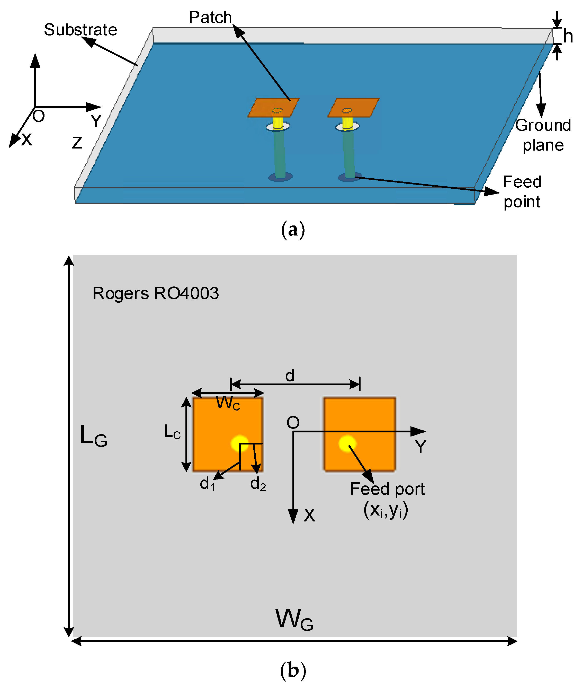
2. Proposed Design
2.1. A. Radiation Modes and Decoupling Mechanism
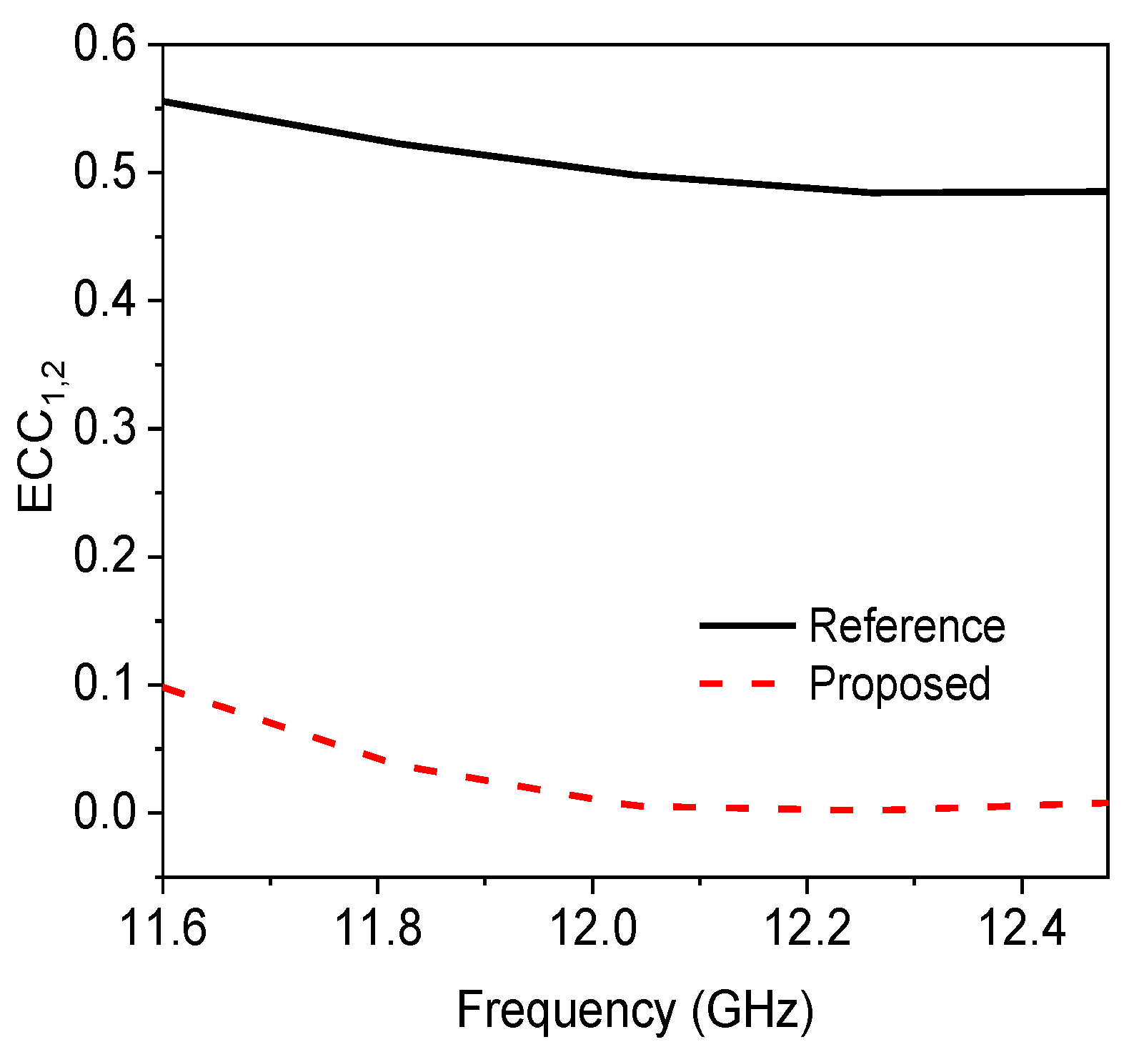
2.2. B. Simulation Verification
3. Experimental Validation
4. Conclusions
Author Contributions
Funding
Data Availability Statement
Conflicts of Interest
References
- Jensen, M.A.; Wallace, J.W. A review of antennas and propagation for MIMO wireless communications. IEEE Trans. Antennas Propag. 2004, 52, 2810–2824. [Google Scholar] [CrossRef] [Green Version]
- Wallace, J.; Jensen, M. Mutual coupling in MIMO wireless systems: A rigorous network theory analysis. IEEE Trans. Wirel. Commun. 2004, 3, 1317–1325. [Google Scholar] [CrossRef] [Green Version]
- Li, M.; Jiang, L.; Yeung, K.L. Novel and efficient parasitic decoupling network for closely coupled antennas. IEEE Trans. Antennas Propag. 2019, 67, 3574–3585. [Google Scholar] [CrossRef]
- Xia, R.L.; Qu, S.W.; Li, P.F.; Jiang, Q.; Nie, Z.P. An efficient decoupling feeding network for microstrip antenna array. IEEE Antennas Wirel. Propag. Lett. 2015, 14, 871–874. [Google Scholar] [CrossRef]
- Farahani, H.S.; Veysi, M.; Kamyab, M.; Tadjalli, A. Mutual coupling reduction in patch antenna arrays using a UC-EBG superstrate. IEEE Antennas Wirel. Propag. Lett. 2010, 9, 57–59. [Google Scholar] [CrossRef]
- Iglesias, E.R.; Teruel, O.Q.; Sanchez, L.I. Planar soft surface and their application to mutual coupling reduction. IEEE Trans. Antennas Propag. 2009, 57, 3852–3859. [Google Scholar] [CrossRef]
- Ghosh, J.; Mitra, D.; Das, S. Mutual coupling reduction of slot antenna array by controlling surface wave propagation. IEEE Trans. Antennas Propag. 2019, 67, 1352–1357. [Google Scholar] [CrossRef]
- Wang, Y.; Du, Z. A wideband printed dual-antenna with three neutralization lines for mobile terminals. IEEE Trans. Antennas Propag. 2014, 62, 1495–1500. [Google Scholar] [CrossRef]
- Chen, X.M.; Tang, M.C.; Yi, D.; Ziolkowski, R.W. Wideband, compact antennas with interdigitated magnetic-based near-field resonant parasitic elements. IEEE Trans. Antennas Propag. 2021, 69, 5036–5041. [Google Scholar] [CrossRef]
- Lin, H.W.; Chen, Q.G.; Ji, Y.; Yang, X.J.; Wang, J.P.; Ge, L. Weak-field-based self-decoupling patch antennas. IEEE Trans. Antennas Propag. 2020, 68, 4208–4217. [Google Scholar] [CrossRef]
- Sun, L.B.; Li, Y.; Zhang, Z.J. Decoupling between extremely closely spaced patch antennas by mode cancellation method. IEEE Trans. Antennas Propag. 2021, 69, 3074–3083. [Google Scholar] [CrossRef]
- Li, M.; Wang, M.; Jiang, L.J.; Yeung, L.K. Decoupling of antennas with adjacent frequency bands using cascaded decoupling network. IEEE Trans. Antenna Propag. 2021, 69, 1173–1178. [Google Scholar] [CrossRef]
- Jeong, J.W.; Park, J.S. A microcontroller unit-based electromagnetic bandgap control scheme: Application for enhancing isolation in an antenna array and the EMI scanner system speed thereof. IEEE Trans. Microw. Theory Tech. 2020, 68, 4536–4553. [Google Scholar] [CrossRef]
- Gao, D.; Cao, Z.X.; Fu, S.D.; Quan, X.; Chen, P. A novel slot-array defected ground structure for decoupling microstrip antenna array. IEEE Trans. Antennas Propag. 2020, 68, 7027–7038. [Google Scholar] [CrossRef]
- Li, M.; Jiang, L.J.; Yeung, K.L. A general and systematic method to design neutralization lines for isolation enhancement in MIMO antenna arrays. IEEE Trans. Veh. Technol. 2020, 69, 6242–6253. [Google Scholar] [CrossRef]
- Li, Z.Y.; Du, Z.W.; Takahashi, M.; Saito, K.; Ito, K. Reducing mutual coupling of MIMO antennas with parasitic elements for mobile terminals. IEEE Trans. Antennas Propag. 2012, 60, 473–481. [Google Scholar] [CrossRef]
- Cheng, Y.-F.; Cheng, K.-K.M. Decoupling of 2 × 2 MIMO Antenna by Using Mixed Radiation Modes and Novel Patch Element Design. IEEE Trans Antennas Propag. 2021, 69, 8204–8213. [Google Scholar] [CrossRef]
- Li, M.; Zhong, B.G.; Cheung, S.W. Isolation enhancement for MIMO patch antennas using near-field resonators as coupling-mode transducers. IEEE Trans. Antennas Propag. 2019, 67, 755–764. [Google Scholar] [CrossRef]
- Cheng, Y.F.; He, Y.; Wu, W.; Chen, C.; Wang, G. Wideband decoupling technique for two-element antenna array by using pixel neutralization line. Microw. Opt. Technol. Lett. 2022, 64, 1785–1792. [Google Scholar] [CrossRef]
- Abbas, A.; Hussain, N.; Sufian, M.A.; Jung, J.; Park, S.M.; Kim, N. Isolation and Gain Improvement of a Rectangular Notch UWB-MIMO Antenna. Sensors 2022, 22, 1460. [Google Scholar] [CrossRef]
- Sufian, M.A.; Hussain, N.; Abbas, A.; Lee, J.; Park, S.G.; Kim, N. Mutual Coupling Reduction of a Circularly Polarized MIMO Antenna Using Parasitic Elements and DGS for V2X Communications. IEEE Access 2022, 10, 56388–56400. [Google Scholar] [CrossRef]
- Bayarzaya, B.; Hussain, N.; Awan, W.A.; Sufian, M.A.; Abbas, A.; Choi, D.; Lee, J.; Kim, N. A Compact MIMO Antenna with Improved Isolation for ISM, Sub-6 GHz, and WLAN Application. Micromachines 2022, 13, 1355. [Google Scholar] [CrossRef] [PubMed]
- Roshani, S.; Shahveisi, H. Mutual Coupling Reduction in Microstrip Patch Antenna Arrays Using Simple Microstrip Resonator. Wirel. Pers. Commun. 2022, 126, 1665–1677. [Google Scholar] [CrossRef]


| LG | WG | d | LC | WC | d1 | d2 | |
|---|---|---|---|---|---|---|---|
| Reference | 50 | 50 | 10 | 5.555 | 6.9 | 1.5 | 4.5 |
| Proposed | 50 | 50 | 10 | 5.700 | 5.3 | 1.98 | 2.0 |
| Ref. No. (Year) | Additional Structure | Element Spacing | Frequency (GHz) | Isolation Enhancement | Peak Efficiency |
|---|---|---|---|---|---|
| [11] (2020) | Required (Connect-Strip) | 0.440 λ0 | 2.39–2.53 | 10 dB | 87% |
| [14] (2020) | Required (DGS) | 0.504 λ0 | 1.25–1.27 | 5 dB/15 dB | N.A. |
| [18] (2019) | Required (Resonators) | 0.260 λ0 | 2.20–2.23 | 12 dB | 74% |
| [19] (2020) | Required (Natura Line) | N.A. | 0.94–0.99 | 17 dB | N.A. |
| This work | Not Required | 0.404 λ0 | 11.61–12.49 | 7 dB | 73% |
Publisher’s Note: MDPI stays neutral with regard to jurisdictional claims in published maps and institutional affiliations. |
© 2022 by the authors. Licensee MDPI, Basel, Switzerland. This article is an open access article distributed under the terms and conditions of the Creative Commons Attribution (CC BY) license (https://creativecommons.org/licenses/by/4.0/).
Share and Cite
He, Y.; Cheng, Y.-F.; Luo, J. Self-Decoupled MIMO Antenna Realized by Adjusting the Feeding Positions. Electronics 2022, 11, 4004. https://doi.org/10.3390/electronics11234004
He Y, Cheng Y-F, Luo J. Self-Decoupled MIMO Antenna Realized by Adjusting the Feeding Positions. Electronics. 2022; 11(23):4004. https://doi.org/10.3390/electronics11234004
Chicago/Turabian StyleHe, Yangyang, Yi-Feng Cheng, and Jiang Luo. 2022. "Self-Decoupled MIMO Antenna Realized by Adjusting the Feeding Positions" Electronics 11, no. 23: 4004. https://doi.org/10.3390/electronics11234004