Article

Flexible Temperature Control Solution for Integrated Circuits Testing—Silicon Creations Thermal Elephant

by
Andrzej Laczewski
1 and
Krzysztof Kasiński
1,2,*
1
Silicon Creations Poland, Av. Conrada 63, 31-357 Kraków, Poland
2
Department of Measurement and Electronics, AGH University of Science and Technology, Av. Mickiewicza 30, 30-059 Kraków, Poland
*
Author to whom correspondence should be addressed.
Electronics 2022, 11(22), 3766; https://doi.org/10.3390/electronics11223766
Submission received: 25 October 2022 / Revised: 14 November 2022 / Accepted: 15 November 2022 / Published: 16 November 2022

Abstract

:
Both scientific and industrial applications require temperature stabilization and enforcement for testing purposes. In this study, we present a solution capable of handling socket-based IC test systems enabling packages from QFN up to FCBGA, or even COB solutions. The temperature range covers the full-range industrial temperature range (−40 °C to +125 °C). The extended temperature range of −55 °C to +150 °C is conditionally possible. Solution supports dry-air installation, safety mechanisms and flexible thermal head assemblies. We present the key features and architecture of the solution named “Thermal Elephant” that found applications in the industrial (characterization of the IP hard macros) and scientific applications (radiation imaging ICs).

1. Introduction and Overview of Existing Solutions

Temperature has an impact on each electronics and microelectronic devices.
Existing solutions available on the market include:
  • Environmental chambers (Figure 1) [1,2,3]. Pros: Universal, low temperature gradient across the low-power systems, moderate price. Cons: No temperature control at the IC package, slow temperature ramping (tens of minutes), high power consumption (few kW), area-consuming (e.g., 70 cm × 70 cm × 170 cm). Requires all components on the PCB to withstand the test conditions.
  • Thermal sockets or socket-compatible thermal heads [4,5,6]. Moderate price. Pros: Fast ramp, good temperature control. Cons: Needs re-design to support different enclosures, which is expensive.
  • Thermoelectric cooler (TEC)-based (Figure 2) [4,7]. Pros: Sufficient temperature range, ramping, dry-air support, moderate price. Cons: Custom-built, rigid dry box. Limited remote control capability.
  • Thermal-stream type solutions [6,7,8,9,10]. Pros: Very wide temperature range (e.g., −120 °C to +300 °C), capable of shock-testing (full swing in tens of s). Cons: Rigid dry box, not easily customizable, high cost.
The scope of this study was to design a cost-effective TEC-based device that would allow testing of the Application-Specific Integrated Circuits (ASICs) in the temperature range of −40 up to +125 °C and beyond; assuming the moderate size of test PCBs and low power dissipation of ASICs (below a few watts). The solution needs to be adaptable to various IC packages (e.g., BGA, QFN, bare-die) and allow long-term operation at various temperature corners (e.g., a few days at −40 °C). Compared to other solutions, the key innovative aspects of the presented solutions are:
  • Water condensation control by flexible, 3D-printed dry-box solution combined with air-flow control that allows frost-free operation, as well as being cost-effective and having fast adaptation to various IC test sockets.
  • Flexible thermal head architecture allowing support of various enclosures and mounting options.

2. System Architecture and Features

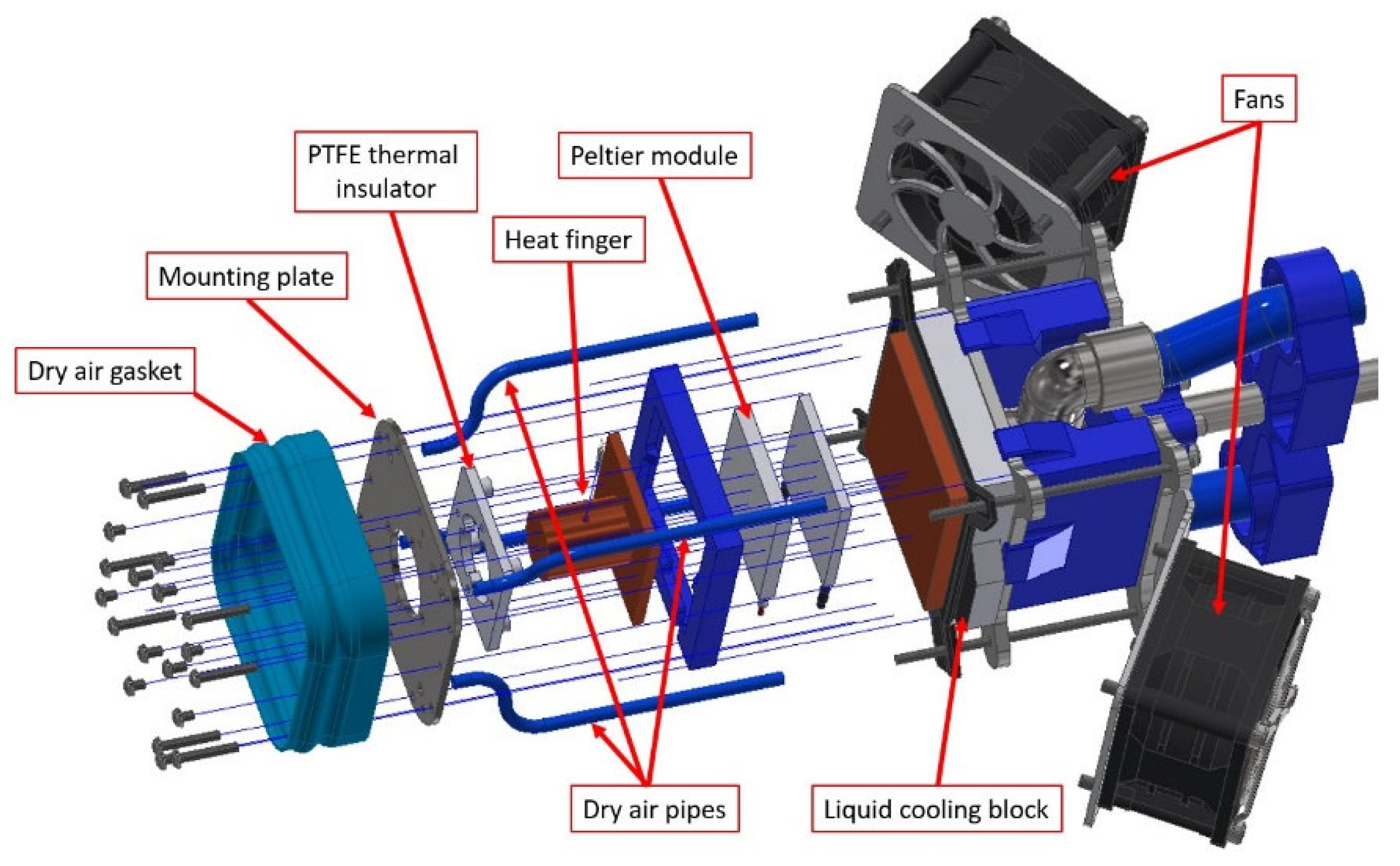
2.1. System Architecture

The temperature of the Device Under Test (DUT) is controlled by means of thermoelectric modules (Peltier modules) located in the thermal head (Figure 3). The heat transfer to the die is via the chips’ enclosure using thermal conduction via the copper milled “heat finger”. The temperature drop is minimized by using quality thermal interface material and the temperature sensing is located at the tip of the copper block.
The TEC stack and the “heat finger” are mounted together with the use of a custom PTFE thermal insulator and a steel mounting plate (Figure 3). Design of the PTFE thermal insulator is optimized in order to minimize heat leakage to the external environment and assembly components (Figure 4). Additionally, a thermal insulating foam is used to seal off any gaps in the thermal head to better control the dry air flow and minimize the water condensation on the internal parts of the head. Minimization of the heat leakage is crucial at lowest temperatures (<−40 °C) due to the reduced TEC heat pumping capability and increased heat leakage via the thermal head, but also via the PCB itself.
The quality of the thermal paste used to connect the components of the thermal head is a factor that is not to be underestimated. Both thermal conductivity and the ability for long-term operation are crucial. Silicon Creations chose IC Diamond [11] thermal compound (3M TCG-2035) that uses artificial diamond powder, resulting in superior thermal conductance of 4.5 W/mK, as well as an extended lifetime during the instrument’s operation compared to other tested thermal compounds. Diamond phononic crystals are used in cutting-edge IC thermal management solutions [12].
The factory-stacked Peltier modules (CUI Devices CP68475H-2 [13]) are supplied from the high-power switching power supply via a low-loss H-bridge, enabling high-frequency (tens of kHz) PWM-based power regulation and polarity reverse option for cooling/heating.
The temperature of the head is measured by the Pt100 sensor located at the tip of the “heat finger” to compensate for any thermal gradient that may occur in the stack. An integrated digitization solution dedicated to precise temperature measurements is used (MAX31865 RTD-to-Digital Converter). Thanks to the calibrated embedded conditioning circuit and 15-bit sigma-delta ADC, the stated accuracy is 0.5 °C (0.05% of full scale). The temperature measurement resolution is 0.03125 °C.
The temperature of the hot side of the Peltier module is stabilized using the commercial liquid cooling block (EK-Quantum Velocity Copper) connected to the commercial chiller (CW-5200).
The system can be manually operated either using the display and keyboard at the front-panel, or remotely operated using the console interface and USB connectivity. This allows integration with the automated test environment.

2.2. Mounting Options

Keeping in mind the flexibility of the designed solution, the thermal head allows for several uses:
  • The DUT is packaged and placed inside a pogo-pin or elastomeric-type test socket. The thermal contact and force required for proper contact between the pins/balls and the socket is applied through a thermal head from the top (Figure 5 and Figure 6).
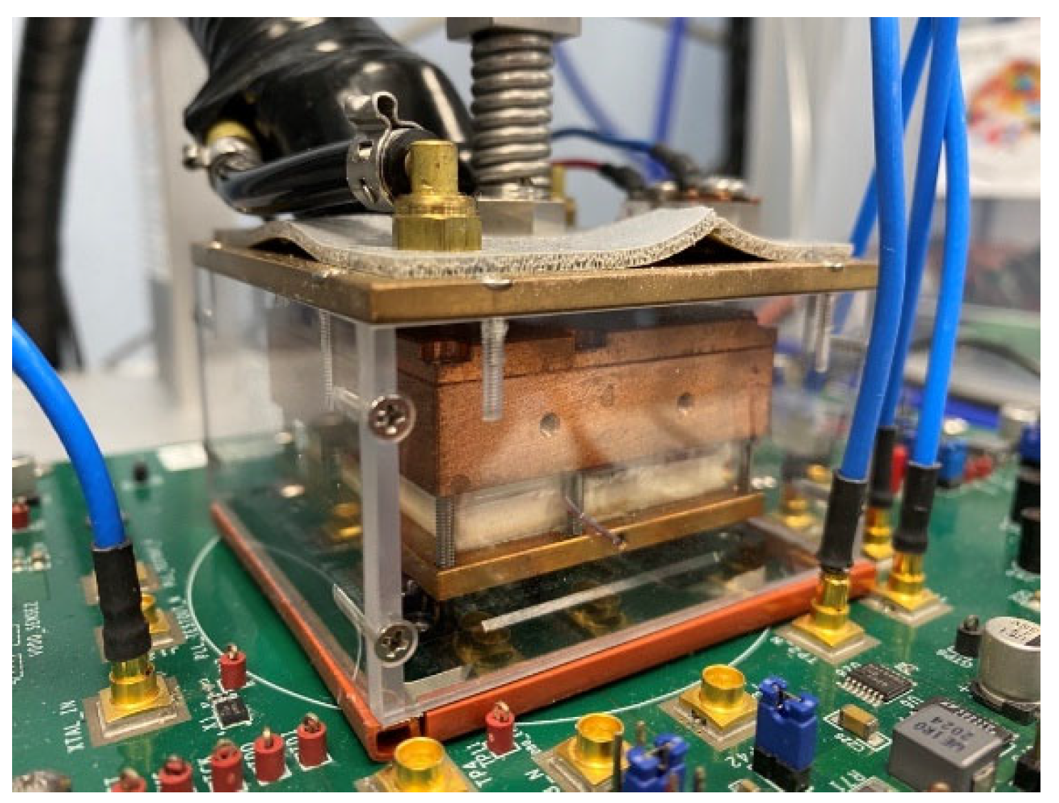
  • The DUT is packaged or as a bare-die (COB) and soldered/wire-bonded to the test PCB. Cooling/heating is applied by the thermal head attached to the bottom side of the PCB and transferred to the DUT via the thermal vias. The thermal head is attached to the larger metal plate which is stabilizing it on the testbench (Figure 7).
  • The DUT is attached, as per the previous instruction, but the thermal head can be freely moved and placed, e.g., inside the irradiation chamber, to perform any kind of imaging or radiation imaging tests.

2.3. Flexibility of the Thermal Head

The thermal head can be mounted in several ways. The default mounting scheme uses the modified ESD trolley (Reeco RF-028-100600-9003 [14]) with a custom clamping arm (Figure 5) to apply force to the DUT and initiate the electrical contact between the chip package and the pogo-pins or elastomeric spacer in the test socket, as well as the good thermal contact between the heat finger and the chip package (via thermal compound). Elastomeric-type sockets may require 10–20 g/ball to initiate proper contact, which, in the case of 1000+ BGA packages, reaches a significant amount of force; thus, the construction of the clamping arm guarantees the stiffness of the whole structure.

2.4. Control of Icing and Water Condensation

Even though the condensed water is almost pure H2O, together with the impurities on the PCB, this can be a problem for the DUT, and particularly when high-impedance circuits or high-voltage circuits are concerned. To limit, and often totally prevent, condensation of water from the surrounding air on the test chips and the test PCBs, the following solutions are presented (Figure 8):
  • Dry-boxes composed of an elastic gasket covering the DUT and the thermal head. The dry air-feed via the valve and splitter block creates dry conditions at the DUT and its neighborhood, thus preventing condensation due to the conditions allowed by the amount of water vapor in the installation. The gasket seals the dry box at the PCB level and the air is forced to flow upwards around the heat finger to escape via dedicated outlets. The gaskets can be easily replaced and adjusted to the target application (3D printed with the use of TPU filament).
  • The top dry box is accompanied by the bottom dry cup, which additionally prevents ice forming at the bottom side of the PCB; something that is often an overlooked, long-term issue when testing at low temperatures. The dry air is fed using a dedicated air hose.
  • Another option to prevent condensation at the bottom side of the PCB is to seal it with adhesive caoutchouc thermal insulating foam with low diffusion capability. This unfortunately does not work with the IC sockets that contain the bottom stiffening plate attached to the PCB.
  • The PCB area outside the dry box is exposed to forced air flow by the fans located at the thermal head that helps evaporate the humidity that might condensate outside the dry box.
Figure 8. Elastic dry-box gasket and the dry air inlets/outlets at the head.
Electronics 11 03766 g008
Dry air is supplied by the industrial compressed dry-air installation. An Atlas-Copco SF1P scroll oil-free compressor feeds the air via the water separator and an adsorption dryer, Beko AC122 (allowing −70 °C dew point at 6 bar), to finally reach the compressed air reservoir. The dry air is then distributed to the end units through the pressure regulators. To protect the lifetime of the compressor and service intervals, the presented solution automatically controls the dry air valve (ON/OFF) to trigger the dry air flow only when needed (i.e., during the cooling process with a setpoint below 10 °C).

2.5. Safety Mechanisms

The control unit (Figure 9) implements several safety mechanisms preventing damage to the equipment, in addition to standard solutions.
  • Monitoring of the water block temperature with use of an external hardware temperature monitoring watchdog. If the chiller fails, the thermal head power supply will be cut off.
  • Monitoring of the Resistance Temperature Detector (RTD), Pt100. Power to the thermal head will be cut off if any of the following faults is detected: open RTD element, RTD shorted to out-of-range voltage, short across RTD element, or measured temperature out of range.
Figure 9. Main board of the unit.
Electronics 11 03766 g009

2.6. Interface

The instrument can be controlled and inspected by the following means:
  • USB serial communication—Thermal Elephant can be controlled remotely via an isolated USB VCOM port. Due to this capability, it can be integrated into automated test solutions. The following commands are available: thermal head enable/disable; change temperature setpoint; read measured thermal head temperature; temperature logging enable/disable; check Pt100 status; set thermal head fan speed; dry air valve enable/disable.
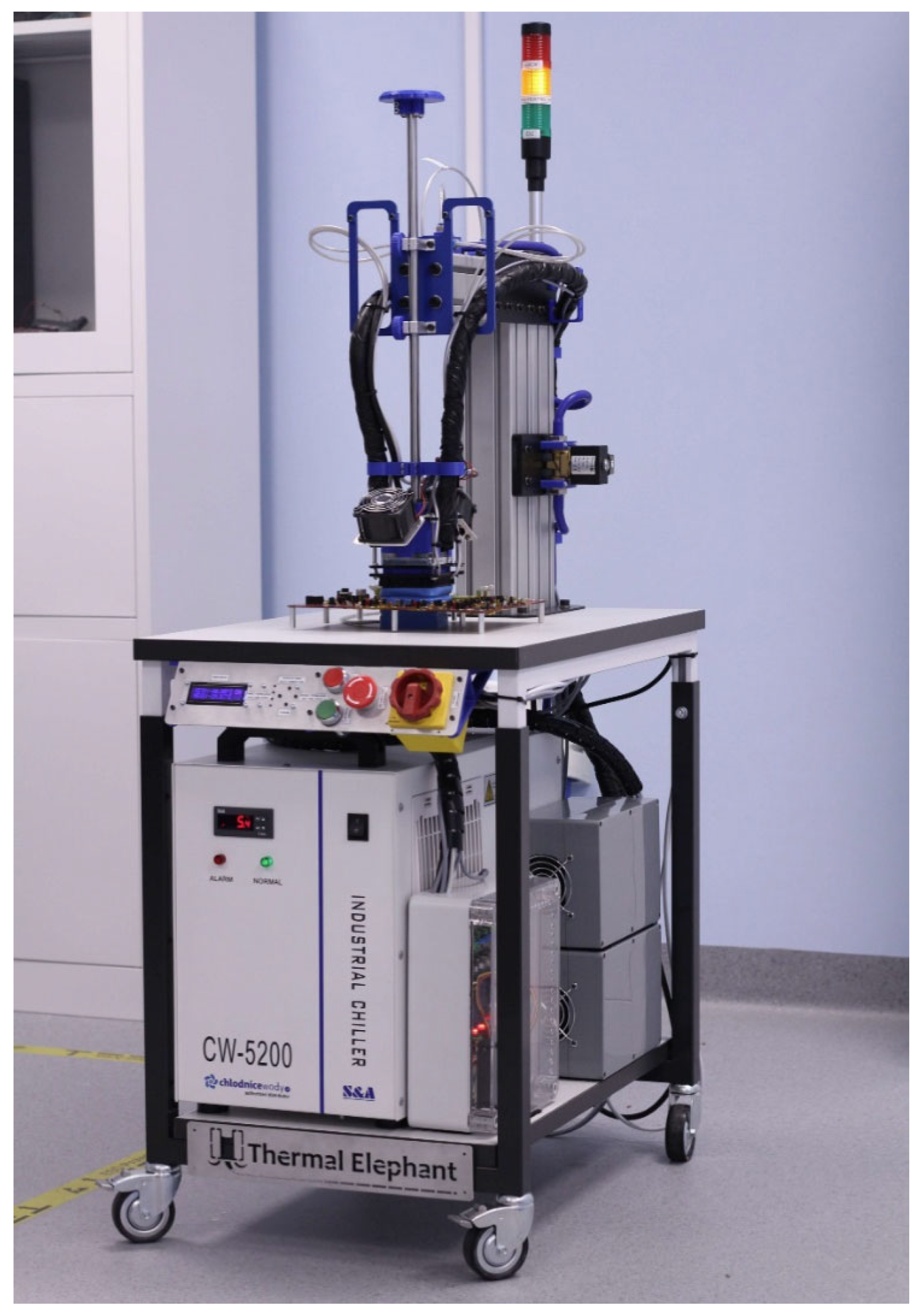
  • Front panel—The user interface located at the front panel consists of: LCD display; pushbuttons; industrial buttons; main power switch (Figure 10). Users can perform the following actions with use of the front panel: read current setpoint and measured temperature; change temperature setpoint; enable and disable the thermal head; force Thermal Elephant into fault state (thermal head power cut off) by pressing emergency stop button.
  • Signaling column and sound messages—This is used to show the current status of the Thermal Elephant. Green light indicates idle state (thermal head disabled); yellow light indicates active state (thermal head enabled); red light together with sound alarm indicates critical fault.

3. Test Results

This section discusses the practical use of the designed solution and the performance evaluation methodology.
The thermal head is capable of achieving very high temperature differences. The key points for success are: selection of the optimal TEC stack; selection of the optimal water block and chiller to evacuate the heat generated by hot side of the TEC; selection of the optimal thermal interface material; optimization of the heat leakage; the architecture of the chilled sample (type of package, method of assembly on the Printed Circuit Board (PCB) and the PCB size). At high temperature differences, the ability to pump the heat significantly drops (see datasheet [13]). At the same time, heat leakage grows (via conduction to the PCB, and then to the environment via convection). This sets the limits of achievable temperatures. The regulation accuracy depends on the setpoint. Examples are presented in Figure 11.

3.1. Exemplary Use Cases

The list below presents some of the applications for which the designed solution has been used in both scientific and industrial applications.
  • Emulation of the system temperature (−22 °C) which is anticipated in the target application: SMX2.2 ASIC for radiation imaging during a CBM experiment at FAIR (Facility of Antiproton and Ion Research) [15], Figure 12.
  • Noise optimization of the hybrid-pixel detector array by lowering the thermal noise of the analog front-end and the detector die itself: UFXC32k ASIC. The thermal head, together with the DUT, were installed in the irradiation chamber of the Rigaku research X-ray generator [16].
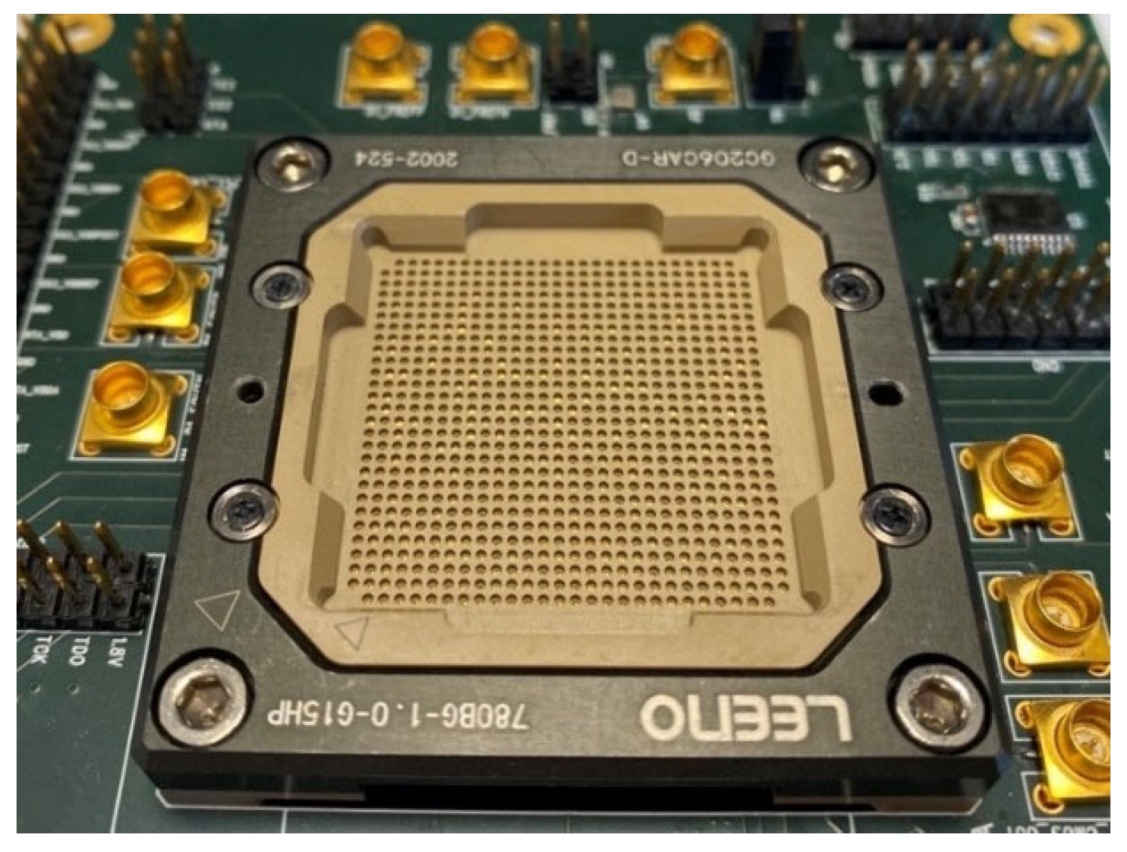
  • IP hard macros characterization across the specified temperature range. For example, Silicon Creations high-performance 14 GHz LC PLL LCPLLTS6FFADA1, 6.4 GHz PLLTS6FFFRACG4 fractional-N ring PLL working with CMLBUFTS6FFGRA on-chip CML buffer and LVDSTS6FFBI1D LVDS I/O in TSMC 6 nm CMOS process in QFN40 enclosure. The solution was also successfully tested with various BGA enclosures placed in both pogo-pin (e.g., UMC 22 nm PLLUM22ULPLVDESKEW1 Deskew PLL) and elastomeric test sockets (e.g., Global Foundries 12 nm process with PLLGF12LPPLUSMFFRACA ring-based, 6.4 GHz PLL and PMAGF12LPPLUSFL1EA1 32Gbps Serdes PMA IP) [17], Figure 10 and Figure 13.
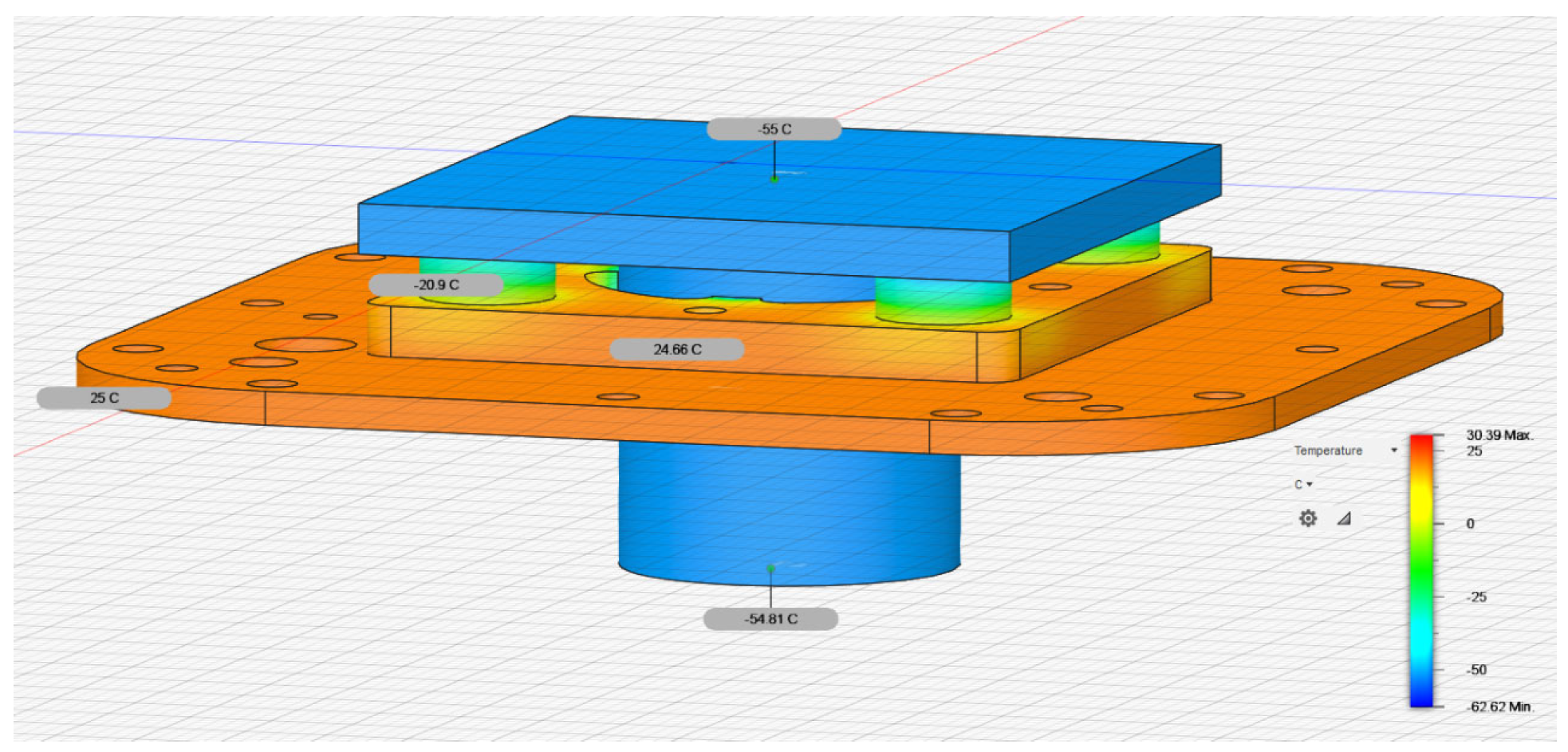
3.2. Validation

The thermal head stabilizes the temperature at the “heat finger”. Particularly in the case of wire-bonded packages and plastic-mold packages, the die temperature is always a concern in cases where the IC is not supplied with a thermal sensor with the required accuracy.
In order to evaluate the real die temperature performance in the system of the exemplary plastic-molded package, an on-chip ESD diode was used as a temperature sensor. An unpowered test chip was placed in the environmental chamber and the I-V points were acquired at biased ESD diodes across different temperatures, allowing the temperature to stabilize for 1 h. The resulting calibration curve was used to evaluate the die temperature of the same test chip while working in the test setup with the Thermal Elephant, with the test PCB attached. The results indicated that for a +125 °C setpoint, the die temperature was 113.7 °C, while for a −40 °C setpoint, it was −31.2 °C. Considering that the plastic molded package is a pessimistic case, the 9-degree offset is a good result which can be corrected by modifying the setpoint. For FCBGA enclosures with metal IHS, the results should be much better. This excludes self-heating effects, which increase the uncertainty of die temperature stabilization.

4. Conclusions

The designed solution has value in industrial and scientific applications. It continues to be used on a daily basis at the Silicon Creations IP Verification and Validation Laboratories in Atlanta and Kraków, testing IPs at commonly specified temperature corners of −40 and +125 °C. The introduced condensation prevention methods allow the DUT to be tested at extreme temperatures for days, without icing occurring. Table 1 presents summary of the features.
The following improvements are planned for implementation:
  • Increased cooling/heating power to enable extended temperature range for larger PCBs and ICs dissipating more power;
  • Optimization of the “heat finger” shape and modularity;
  • Spring-loaded mechanism for force application and achieving coplanarity between the finger and the package;
  • Force measurement mechanism for precise regulation of applied force according to the socket’s datasheet (e.g., 20 g/ball for BGA packages with low inductance elastomeric spacer);
  • Thermal head redesign for easier maintenance;
  • Additional Pt100 sensor to be placed at the test chip enclosure to monitor (and compensate, if needed) the temperature gradient across the thermal interface material.

Author Contributions

A.L.: investigation, design, assembly, software, validation, K.K.: conceptualization, writing, supervision, funding acquisition, validation. All authors have read and agreed to the published version of the manuscript.

Funding

This research received no external funding.

Institutional Review Board Statement

Not applicable.

Informed Consent Statement

Not applicable.

Data Availability Statement

Not Applicable.

Acknowledgments

This work was partially developed using resources of the Interdisciplinary Research Laboratory (ILB) at AGH University of Science and Technology. The research results presented in this paper have been developed with the use of equipment financed from the funds of the “Excellence Initiative—Research University” program at AGH University of Science and Technology.

Conflicts of Interest

K.K. was co-editor of the special issue, but did not have any impact on the decision. The funders had impact on the design of the solution, but had no role in its validation.

References

  1. Available online: https://www.thermalproductsolutions.com/ (accessed on 1 August 2022).
  2. Available online: https://www.cts-umweltsimulation.de/en/ (accessed on 1 August 2022).
  3. Available online: https://www.dellamarca.it/en/ (accessed on 1 August 2022).
  4. Available online: https://www.siliconthermal.com/pages/companyoverview.htm (accessed on 1 August 2022).
  5. Available online: https://www.exatrontestsockets.com/ (accessed on 1 August 2022).
  6. Available online: https://www.smithsinterconnect.com/ (accessed on 1 August 2022).
  7. Available online: https://mechanical-devices.com (accessed on 1 August 2022).
  8. Available online: https://www.lneya.com/special-chiller/Chip-Impact-Test.html (accessed on 1 August 2022).
  9. Available online: https://www.intestthermal.com/temptronic (accessed on 1 August 2022).
  10. Available online: https://mpi-thermal.com/applications/semiconductor-ic-devices/ (accessed on 1 August 2022).
  11. Available online: https://www.innovationcooling.com/products/ic-diamond/ (accessed on 1 August 2022).
  12. Available online: https://phononic.com/solid-state-technology/ (accessed on 1 August 2022).
  13. CP68475H-2 Datasheet, Rev 1.02, CUI Devices. Available online: https://www.cuidevices.com/product/thermal-management/peltier-devices/multi-stage-peltier-modules/cp68475h-2 (accessed on 24 October 2022).
  14. Available online: https://renex.pl (accessed on 1 August 2022).
  15. Kasinski, K.; Rodriguez-Rodriguez, A.; Lehnert, J.; Zubrzycka, W.; Szczygiel, R.; Otfinowski, P.; Kleczek, R.; Schmidt, C.J. Characterization of the STS/MUCH-XYTER2, a 128-channel time and amplitude measurement IC for gas and silicon microstrip sensors. Nucl. Instrum. Methods Phys. Res. Sect. A Accel. Spectrometers Detect. Assoc. Equip. 2018, 908, 225–235. [Google Scholar] [CrossRef]
  16. Kasinski, K.; Grybos, P.; Kmon, P.; Maj, P.; Szczygiel, R.; Zoschke, K. Development of a Four-Side Buttable X-Ray Detection Module with Low Dead Area Using the UFXC32k Chips with TSVs. IEEE Trans. Nucl. Sci. 2017, 64, 2433–2440. [Google Scholar] [CrossRef]
  17. Available online: https://www.siliconcr.com (accessed on 1 August 2022).
Figure 1. Tenney environmental chamber at a phase-locked loop characterization testbench in the Silicon Creations Laboratory.
Electronics 11 03766 g001
Figure 2. Commercial thermal control solution in Silicon Creations Laboratory.
Electronics 11 03766 g002
Figure 3. Exploded view of the thermal head containing replaceable “heat finger”.
Electronics 11 03766 g003
Figure 4. PTFE thermal insulator simulation.
Electronics 11 03766 g004
Figure 5. Socket-based test setup mounting option.
Electronics 11 03766 g005
Figure 6. Example of supported sockets (pogo-pin socket for BGA package with clamshell lid removed).
Electronics 11 03766 g006
Figure 7. Chip-on board mounting option.
Electronics 11 03766 g007
Figure 10. Photo of the Silicon Creations Thermal Elephant Unit for handling socket-based testing systems.
Electronics 11 03766 g010
Figure 11. Measured stability of the temperature regulation for heating up to +120 °C (top) and cooling down to −10 °C (bottom).
Electronics 11 03766 g011
Figure 12. Photo of the Thermal Elephant Unit for scientific radiation imaging systems testing at AGH University of Science and Technology.
Electronics 11 03766 g012
Figure 13. Dry air installation in the Silicon Creations Laboratory supplying thermal chambers and Thermal Elephant units with the dry air.
Electronics 11 03766 g013
Table 1. Key parameters of the presented solution.
ParameterMinMax
Temperature range (standard)−40 °C+125 °C
Temperature range (extended)−55 °C+150 °C
Temperature measurement resolution0.3125 °C
Temperature regulation accuracyApprox. ±0.5 °C
Temperature settling time (1% of the setpoint)20 °C down to −40 °C in 200 s
Power consumption (including chiller) 1 kW
Supported enclosuresQFN 5 mm × 5 mmBGA > 35 mm × 35 mm
Publisher’s Note: MDPI stays neutral with regard to jurisdictional claims in published maps and institutional affiliations.

