Article

A Strain Rate Dependent Damage Model for Evaluating the Dynamic Response of CFRTP Laminates with Different Stacking Sequence

1
Beijing Key Laboratory of Lightweight Metal Forming, Beijing 100083, China
2
School of Mechanical Engineering, University of Science and Technology Beijing, Beijing 100083, China
*
Author to whom correspondence should be addressed.
Electronics 2022, 11(22), 3728; https://doi.org/10.3390/electronics11223728
Submission received: 22 October 2022 / Revised: 7 November 2022 / Accepted: 8 November 2022 / Published: 14 November 2022

Abstract

:
Carbon fiber reinforced thermoplastic polymer (CFRTP) laminates can be used in packaging electronics components to reduce weight and shield external disturbance. The CFRTP structures in operation are inevitably to suffer dynamic loading conditions such as falling rocks, tools and impacts. In this study, a strain rate dependent material model for accurately evaluating the dynamic response of CFRTP laminates with different stacking sequence was proposed. The model was composed of three components: a strain rate dependent constitute model, a strain rate related damage initiation model and an energy-based damage evolution model. The strain rate effect of modulus and strength was described by a stacking sequence related matrix, and the damage initiation model could describe the matrix, fiber and delamination damage of CFRTP laminates without introducing cohesive elements. The material model was implemented into finite element software ABAQUS by user defines subroutine VUMAT. The low velocity impact tests of CFRTP laminates with quasi-isotropic and angle-ply stacking sequence were used to provide validation data. The dynamic response of CFRTP laminates from numerical results were highly consistent with the experimental results. The mechanical response of CFRTP laminates were affected by stacking sequence and impact energy, and the numerical error of proposed material model significantly decreased with the increasing impact energy especially for the laminae with damage occur.

1. Introduction

Carbon fiber reinforced thermoplastic (CFRTP) laminates have considerable potential for lightweight use in electronic shields, aerospace, automotive, wind energy and marine due to their high specific stiffness and strength, corrosion resistance, fatigue performance and recyclability [1,2,3]. In structural applications, CFRTP laminates are inevitably exposed to the low velocity dynamic loading condition such as tool dropping, debris impact, and bird impact [4]. The dynamic loading issues cause barely visible impact damage (BVID), and should be crucially considered for strength assessment of composite structures.
To thoroughly investigate the dynamic response of composite laminates, many numerical investigations have been conducted in the past several decades, but few of them considered strain rate effects. Actually, due to the viscose-plastic of thermoplastic matrix, the strain rate sensitivity of CFRTP laminates cannot be neglected even if in the low strain rate loading condition. For example, Massaq et al. [5] claimed that the failure stress and failure energy of PA6/Glass showed obvious strain rate sensitivity in the strain rate range from 10−5 s−1 to 1 s−1 and 100 s−1 to 2500 s−1, respectively. Chen et al. [6] showed the failure strain of PEEK composites increased apparently with the strain rate increasing from 0.001 s−1 to 1000 s−1. Ou et al. [7] investigated the effect of strain rate on the mechanical properties and failure patterns of GFRP and reported that tensile strength, maximum strain and toughness increase with increasing strain rates from 1/600 s−1 to 160 s−1. The authors previous research also revealed that the strain rate sensitivity of CFRTP laminates was obvious from strain rate 2 × 10⁻⁴ s−1 to 2200 s−1 [8]. The strain rate sensitivity was one of the key factors an accurate assessment of composite tensile strength and fracture toughness under dynamic loadings [9,10].
The phase field initiated in 1990s, has received a significant development in the recent years [11,12,13]. It is widely used for composite laminates and the progressive failure [14,15]. The implementation of traditional damage model could be more easier as only the material properties on the integration points of the elements are required to be modified [16]. Thus, a material model involving strain rate effects based on continuum mechanics was proposed in this study. Normally, the constitute behaviour of composite laminate is assumed to be linear deformation and the non-linear mechanical response is mainly due to the damage formation and expansion. Thus, damage imitation and evolution model are the research focus in the past decades. Typical failure modes in composite laminates include matrix damage, fiber damage and delamination damage. Some widely used failure criteria such as Tai-Wu criterion [17], Hashin [18] and Hou [19,20] criteria can predict fiber and matrix damage, but none of them considered the effect of strain rate. Yen and Caiazoo [21,22] proposed a model to determine the stiffness and strength of composite materials at various strain rate levels [23,24]. Based on Y-C function, Wang et al. [25] proposed a three-dimensional strain-rate-dependent damage model which can predict the strain rate dependent contact force curve and damage modes. However, the aforementioned failure criteria cannot directly predict delamination damage of composite laminates. They additionally introduced cohesive zone elements to predict the mechanical behaviour of interface, which significantly increased the computation cost and may lead to the distortion of adjacent elements.
Additional, the dynamic behaviour of CFRTP laminates were affected by not only strain rate but also stacking sequence [26,27]. The strain rate sensitivity in matrix dominant direction was normally more obvious than fiber dominant direction. Hence, the effect of stacking sequence on the strain rate needed to be considered in the finite element modelling analysis of dynamic mechanical properties of CCFRT laminates.
The objective of this study is to present a strain rate related material model for accurately evaluating the dynamic response of CFRTP laminates with different stacking sequence. The established model included a strain rate related constitute model, a strain rate related damage initiation model, and an energy based damage evolution model. The strain rate related modulus and strength were evaluated by introducing a matrix for describing stacking sequence effect. The damage initiation model was established based on Hou criteria including fiber damage, matrix damage and delamination criteria. The material model was implemented in the ABAQUS/Explicit by user subroutine codes. Low velocity impact tests of CFRTP laminate plates with quasi-isotropic and angle-ply stacking sequence were used to validate the proposed model. Detailed strength and failure mode comparisons between the numerical predictions and experimental results were discussed.

2. Strain Rate Relate Dependent Material Model

To model the constitute behavior of CFRTP lamina, fiber direction, in-plane perpendicular to the fiber direction, out-of-plane perpendicular to the fiber direction were respectively defined as Direction 1, Direction 2 and Direction 3, as is shown in Figure 1.

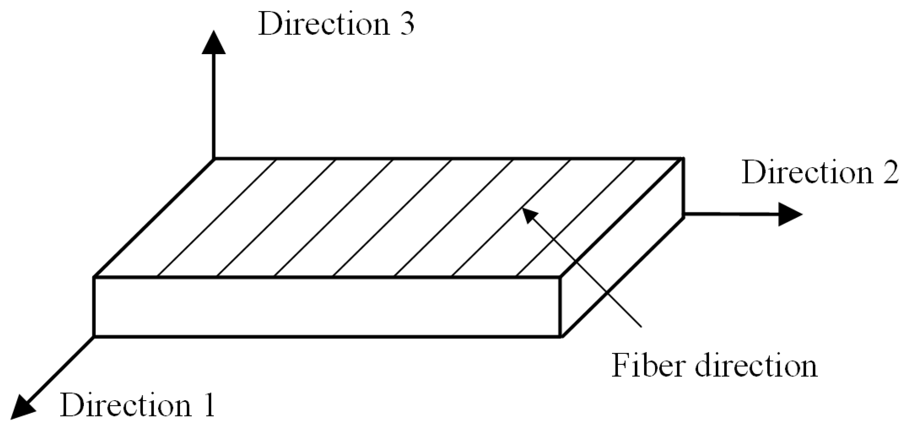
2.1. Constitute Model

A three dimensional constitute model for orthotropic composite can be expressed as:
σ = C × ε
where σ , C   and ε are stress matrix, stiffness matrix and strain matrix, respectively. σ = [ σ 11 σ 22 σ 33 τ 12 τ 23 τ 31 ] T , ε = [ ε 11 ε 22 ε 33 γ 12 γ 23 γ 31 ] T .
In the static condition, the stiffness matrix of CFRTP laminate can be expressed as:
C = [ C 11 C 12 C 13 C 22 C 23 C 33 C 44 C 55 C 66 ]
where C 11 = 1 υ 23 υ 32 E 22 E 33 Δ , C 12 = υ 21 + υ 23 υ 31 E 11 E 33 Δ , C 22 = 1 υ 13 υ 31 E 11 E 33 Δ ,   C 13 = υ 31 + υ 21 υ 32 E 11 E 22 Δ , C 23 = υ 32 + υ 12 υ 31 E 11 E 22 Δ ,   C 33 = 1 υ 12 υ 21 E 11 E 22 Δ , C 44 = E 12 , C 55 = E 13 , C 66 = E 23 , υ i j E i i = υ j i E j j , Δ = 1 υ 13 υ 31 υ 12 υ 21 υ 23 υ 32 2 υ 12 υ 32 υ 31 E 11 E 22 E 33 ; E i j   and υ i j   ( i , j = 1 , 2 , 3 ) are the elastic modulus and poisson’s ratio, respectively.
According to the logarithmic function established by Yen and Caiazzo [22], a matrix was introduced to describe the strain rate related modulus as:
DIF i j e = 1 + m i j e × l n ( ε ˙ / ε 0 ˙ ) , E i j * = E i j × DIF i j e ( i , j = 1 , 2 , 3 )
where m i j e ( i , j = 1 , 2 , 3 ) was the component in the matrix. ε ˙ was the loading strain rate. ε 0 ˙ was the reference strain rate, which was 2 × 10 4   s 1 in this study. E i j * and E i j were the strain rate related modulus and reference modulus, respectively.

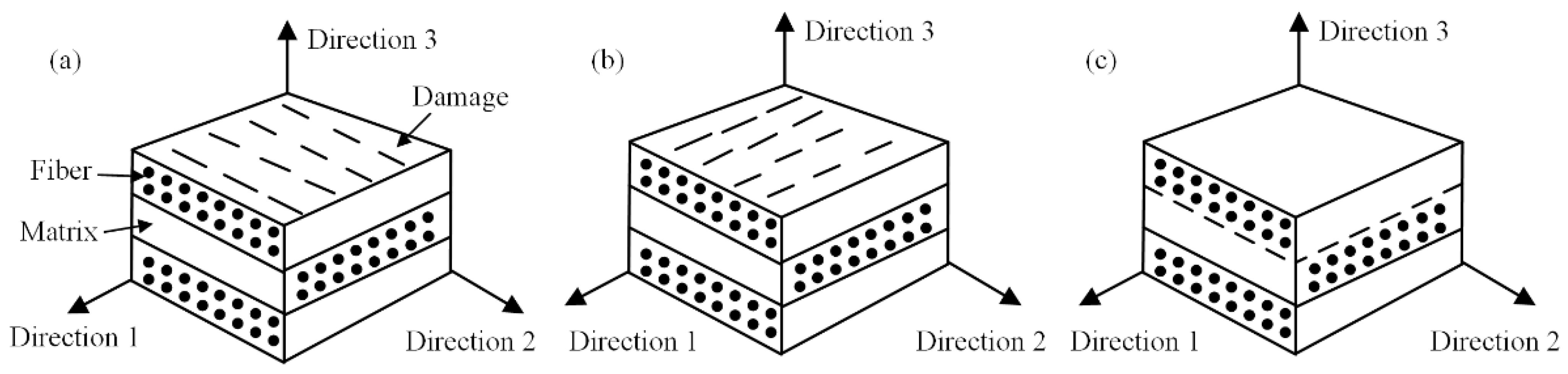
2.2. Damage Initiation Model

Hou failure criteria including fiber damage and matrix damage were used to predict material damage initiation, and a traction separation model was introduced to predict delamination damage as [19,28,29]:
Fiber damage:
f 1 2 = { ( σ 11 σ 11 f , t ) 2 σ 11 0   ( σ 11 σ 11 f , c ) 2 σ 11 < 0  
Matrix damage:
f 2 2 = { ( σ 22 σ 22 f , t ) 2 + ( σ 12 σ 12 f ) 2 + ( σ 23 σ 23 f ) 2   σ 22 0   ( σ 22 + σ 33 2 σ 23 f ) 2 + σ 22 f , c σ 22 ( 2 σ 12 f ) 2 σ 12 σ 12 f + ( σ 12 σ 12 f ) 2 σ 22 < 0  
Delamination damage:
f 3 2 = { ( σ 33 σ 33 f , t ) 2 + ( σ 13 σ 13 f ) 2 + ( σ 23 σ 23 f ) 2   σ 33 0 ( σ 13 σ 13 f ) 2 + ( σ 23 σ 23 f ) 2   σ 33 0  
where σ i i f , t and   σ i i f , c ( i = 1 , 2 , 3 ) represented the tensile and compression strength in direction i. σ 12 f   is the in plane shear strength. σ 13 f and σ 23 f are the out of plane shear strength. f i   ( i = 1 , 2 , 3 ) represents the damage state: f i < 1 represents undamaged state, and f i 1 represents damaged state.
A dynamic increased factor matrix is introduced to describe the strain rate related strength of CFRTP laminates as:
DIF i j s = 1 + m i j s × l n ( ε ˙ / ε 0 ˙ ) , S i j * = S i j × DIF i j s ( i , j = 1 , 2 , 3 )
where m i j s is the strain rate constants for describing the material strength strain rate sensitivity. ε ˙ is the loading strain rate. ε 0 ˙ is the reference strain rate, which is 2 × 10 4   s 1 in this study. S i j * and S i j   are the strain rate related strength and reference strength, respectively.

2.3. Damage Evolution Model

To described the damage evolution of CFRTP laminate, d i ( i = 1 , 2 , 3 ) was defined to characterize the damage state of in material. d 1 represents the damage in direction 1, which can be quantified as the in-plane damage distribution density perpendicular to the fiber (Figure 2a). d 2 represents the damage in direction 2, which can be quantified as the in-plane damage distribution density along the fiber direction (Figure 2b). d 3 represents the damage in direction 3, which can be quantified as the out of plane damage distribution density (Figure 2c). The value of d i is between 0 and 1. d i = 0 represents the material is no damage in direction i ; d i = 1 represents the material fails in direction i   [30].
An energy-based criterion is used to describe the nonlinear damage evolution as [31]:
d i = 1 exp ( σ i i f δ e q , i i f ( f i 1 ) / G i ) / f i
where G i represents the fracture energy in direction i ; δ e q , i i f represents the equivalent displacement in relative direction and can be expressed as [32]:
δ e q , i i f = { σ i i f , t L C C i i   σ i i 0 ,   i = 1 , 2 σ i i f , c L C C i i   σ i i < 0 ,   i = 1 , 2  
in which L C is the feature length of element.
Once the damage initiation criterion is satisfied, the constitute model of composite laminate is defined as:
σ = C d × ε
the damaged stiffness matrix C d can be expressed as:
C d = [ C 11 d C 12 d C 13 d C 22 d C 23 d C 33 d C 44 d C 55 d C 66 d ]
C 11 d = ( 1 d 1 ) C 11 ,   C 22 d = ( 1 d 2 ) C 22 ,   C 33 d = ( 1 d 3 ) C 33 ,   C 12 d = ( 1 d 1 ) ( 1 d 2 ) C 12 ,   C 23 d = ( 1 d 2 ) ( 1 d 3 ) C 23 ,     C 13 d = ( 1 d 1 ) ( 1 d 3 ) C 13 , C 44 d = ( 1 d 1 ) ( 1 d 2 ) C 44 ,   C 55 d = ( 1 d 1 ) ( 1 d 3 ) C 55 ,   C 66 d = ( 1 d 2 ) ( 1 d 3 ) C 12

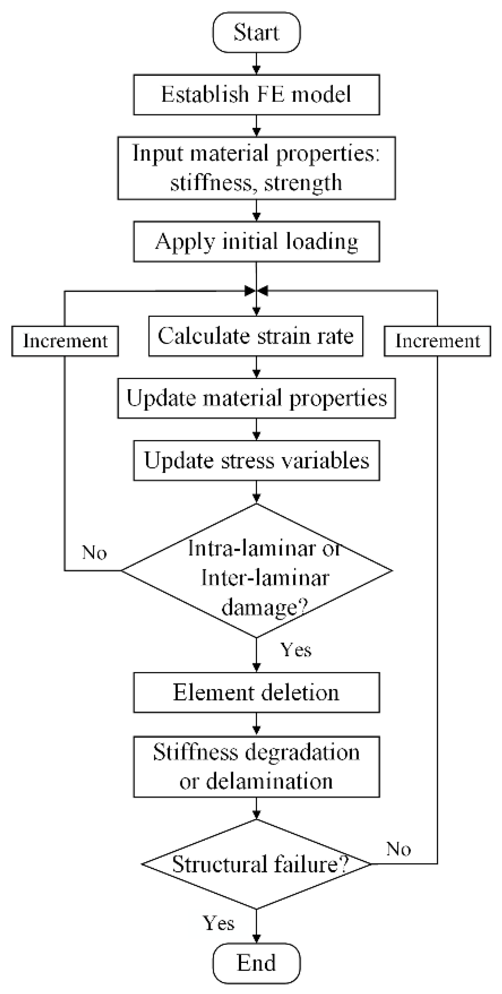
2.4. Model Implementation

The strain rate related constitute model, strain rate related damage initiation model and energy based damage evolution model were implemented in finite element software ABAQUS by user subroutine VUMAT. The simulation flowchart is shown in Figure 3. Firstly, the mechanical parameters including material modulus and strength at the reference strain rate and the state variables in the previous increment were imported in the established finite element model. Secondly, the strain rate, as well as the strain rate related modulus and strength of the material in the current increment, were calculated according to the strain increment and time increment. Thirdly, the damage state is examined according to the intra-laminar and inter-laminar damage model. If the damage occurs, the stiffness degradation or delamination is conducted. Otherwise, status variable is updated and the model goes to the next incremental step. Finally, the time increment is calculated and the model goes to the next incremental step.

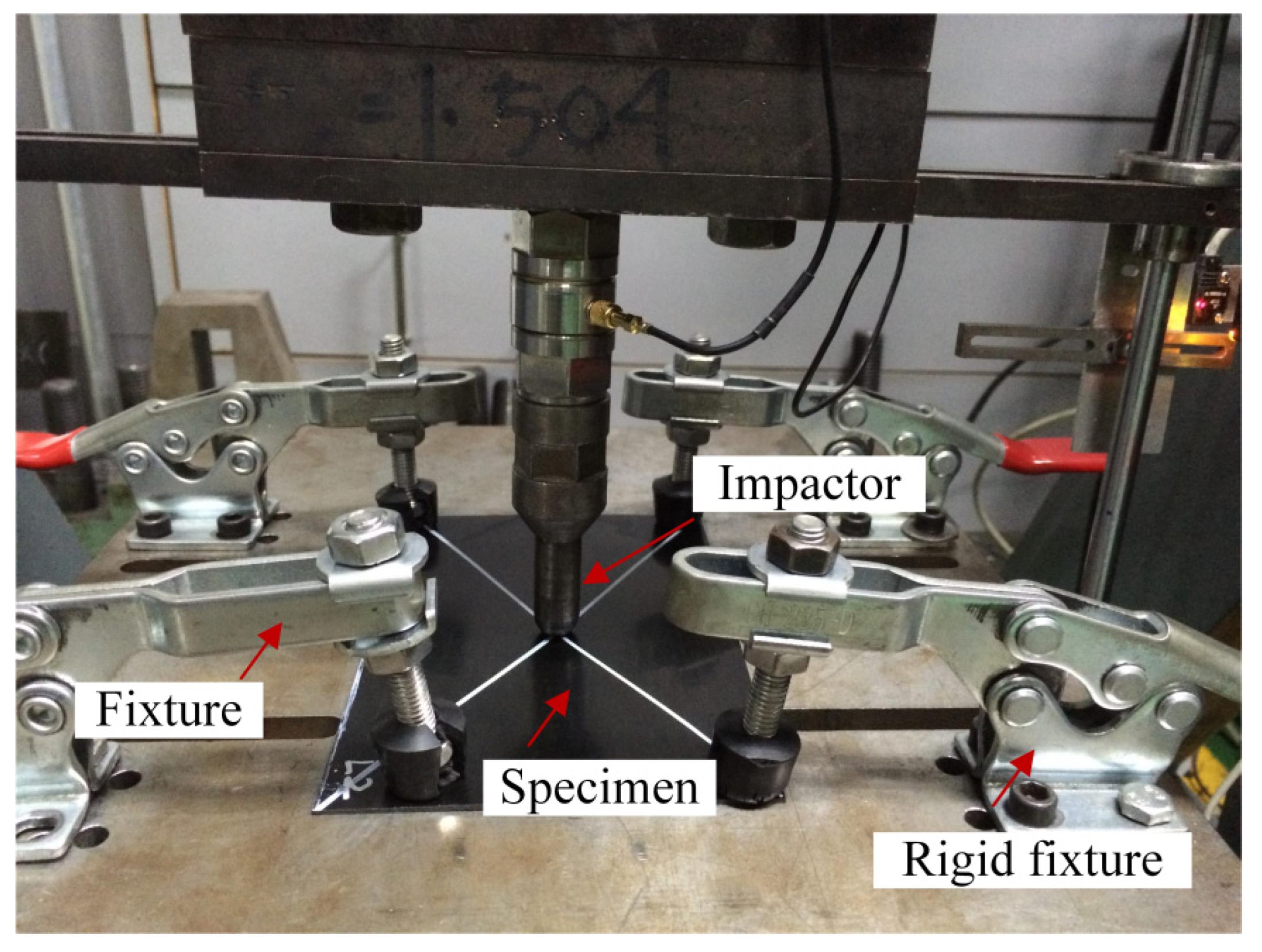
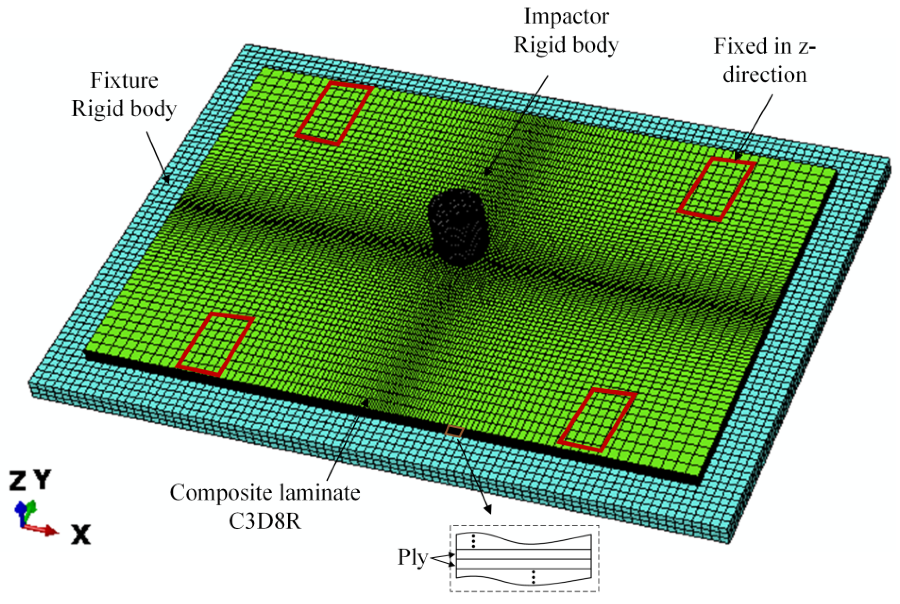
3. Experimental Method
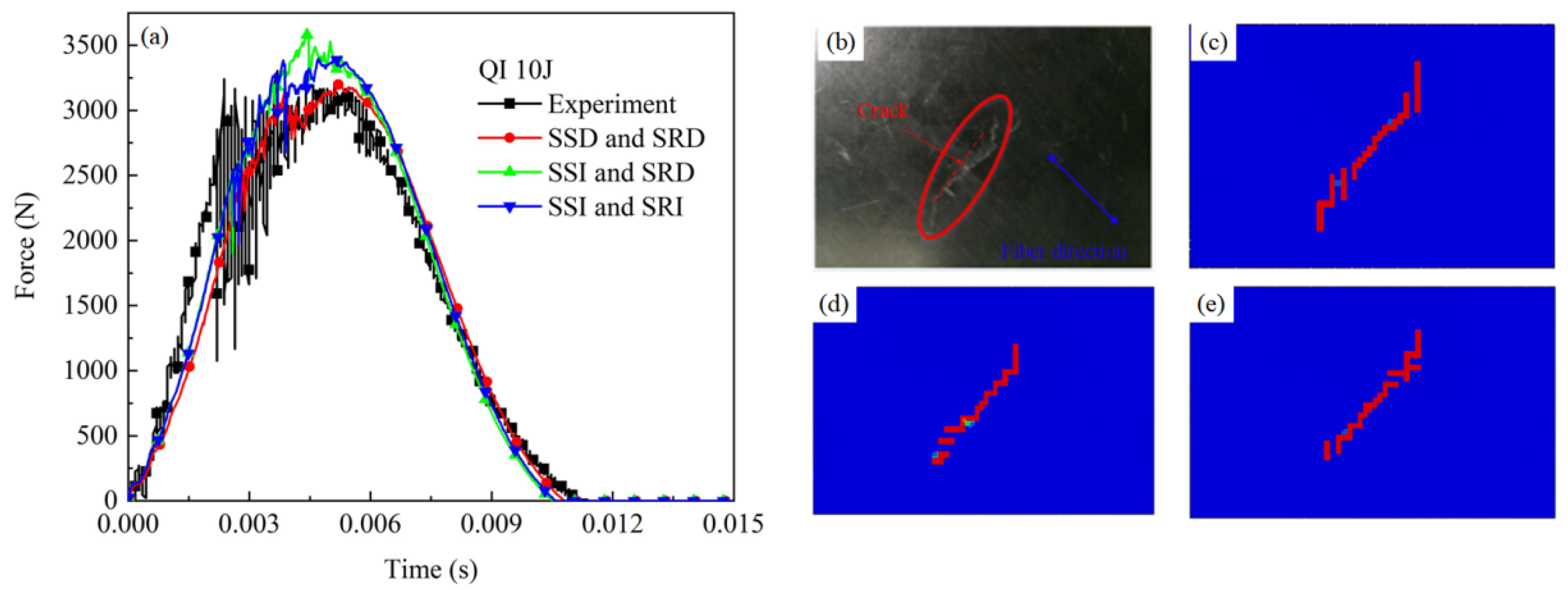
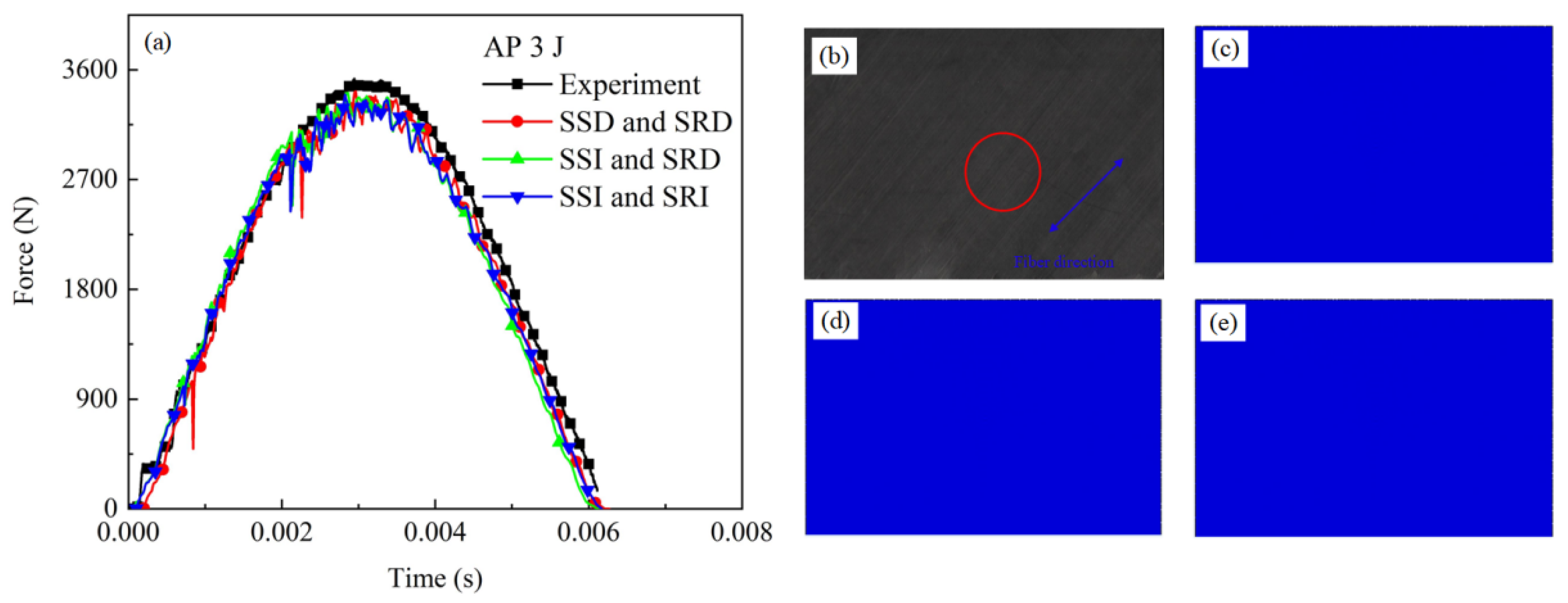
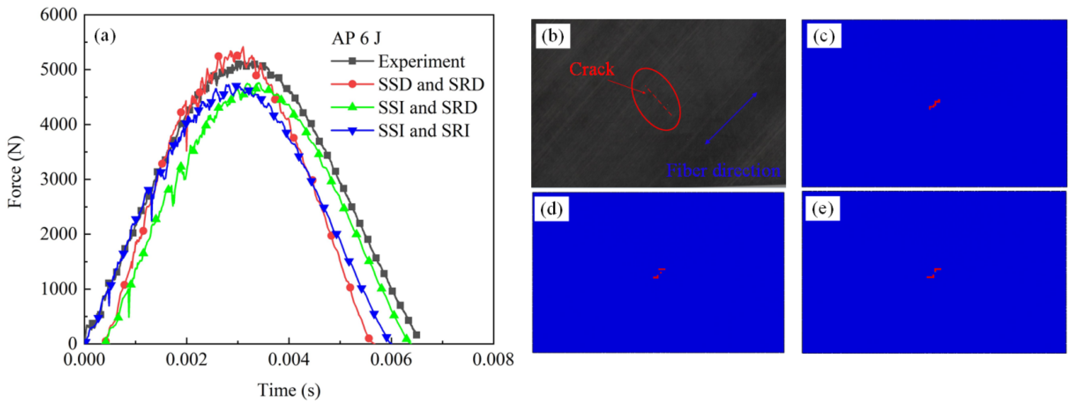
The LVI experiments of CFRTP laminates was conducted with INSTRON CEAST 9350 impact test system in accordance with ASTM D7136 (Manufacture: American Society of Testing Materials; City: PA; Country: American) [33]. The rectangular specimens with length of 150 mm, width of 100 mm and thickness of 2.6 mm for quasi-isotropic and thickness 3.0 mm for angle-ply stacking sequence (Figure 4). The LVI specimens were fixed on the rigid support by four clamps to prevent the longitudinal vibration of the specimen. The fixture has 125 mm × 75 mm rectangular cut, and the impact point located at the center of rectangular cut. The steel hemispherical impactor was 5.5 kg weigh and 12.7 diameter. The LVI experiments were conducted at room temperature, and there is no obvious electromagnetic and vibration. For quasi-isotropic (QI) laminate, the matrix was PA and the reinforced component was carbon fiber; the impact energy was 10 J; For angle-ply (AP) laminate, the matrix was PC and the reinforced component was carbon fiber; the impact energy was 3 J and 6 J. The impact speed is determined by the impact energy and the initial height of the punch along the impact direction according to Formula (12)
E imp = mg h = 1 2 mv imp 2
where E imp is the impact energy; m is the impactor mass;   h is the initial impactor height, and v imp is the initial impactor velocity; The contact force history was recorded by a sensor in the test system.

4. Model Validation

Figure 5 showed the finite element model of LVI experiments of CFRTP laminates. The model included three components: a support, a sample and an impactor. The support and impactor were modeled by rigid bodies, and the composite laminate sample were modeled by C3D8R solid elements with a minimum element size of 0.8 mm × 0.8 mm. One element was used for each layer in the thickness direction. Rigid supports was constrained all the freedom in the transition and rotation direction. Four pressure heads on the specimen were simplified as constraint in the impact direction. The impactor was applied an initial impact speed according to experiments. The surface contact between the impactor and the CFRTP specimen was adopted. The material parameter of QI and AP laminate were listed in Table 1 and Table 2, respectively.
Normally the modulus and strength of CFRTP in Direction 2 and Direction 3 were assumed to be equivalent as material properties in these two directions were affected by matrix. Thus, the strain rate parameter m 22 and m 33 was unified expressed by m 2 , and m 12 , m 23 and m 13 was unified expressed by m 3 . The material parameters of QI and AP laminate were listed in Table 1 and Table 2, respectively.
The contact force history of QI laminate under 10 J impact from experiment and simulation results were compared in Figure 6a. It can be seen that the contact force history curves from three simulation models and test have similar trends. Firstly, the contact force increased with impact propagation, and the growth rate decreased when the damage threshold was reached. With the damage propagation, the contact force continued to increase with a slow rate until reaching the peak value. Then, the impactor starts to rebound and the contact force gradually decreases to zero. The failure pattern of QI laminate under 10 J impact from experimental and simulation results were compared in Figure 6b–e. There were obvious cracks caused by fiber fracture on the laminated plate, and the cracks extend linearly along the 45° direction (the red circle). The damage area from SSD and SRD model was larger than that from the other two models as the failure evolution process were evidently accelerated according to the proposed criteria.
The contact force history of AP laminate under 3 J impact from experiment and simulation results were compared in Figure 7a. The contact force from experimental results, SSD and SRD, SSI and SRD, SSI and SRI simulation results were similar. The curve firstly increased with the increasing contact time, and then decreased after reaching the maximum value. The failure pattern of AP laminate under 3 J impact from experimental and simulation results were compared in Figure 6b–e. There were no obvious damage on the composite surface, which was reflected by all the three simulation results.
The contact force history of AP laminate under 6 J impact from experiment and simulation results were compared in Figure 8a. Similarly, the contact force from experiments, SSD and SRD, SSI and SRD, SSI and SRI numerical models were quadratic function type. The failure pattern of AP laminate under 6 J impact from experimental and simulation results were compared in Figure 6b–e. The cracks from simulation results were on the impact point and along the fiber direction, which was similar to the experimental results. Moreover, the crack in SSD and SRD model was more continuity than other two models. It indicated that the failure evolution process were evidently in SSD and SRD model.
The detailed maximum contact force from experiment and simulation models were listed in Table 3. It can be seen that the simulation error decreased significantly in the SSD and SRD material model compared to the other two material model for both QI and AP laminate. Moreover, the simulation error for AP laminate under 3 J energy impact was decreased by 21.6% (from 2.9% to 3.7%), and the value was 40.5% (from 8.4% to 5%) for AP laminate under 6 J. The simulation error was decreased with the increasing strain rate especially for the laminae with damage occur.

5. Conclusions

This paper proposed a strain rate dependent damage model for evaluating the dynamic response of CFRTP laminates with different stacking sequence. In this model, a strain-stress relationship as well as matrix damage, fiber damage and delamination damage criteria considering strain rate effect were established and implemented into finite element software ABAQUS by user defined subroutine. The low velocity impact experiments at different impact energies on quasi-isotropic laminate and angle-ply laminae were also used to validate the model. It was found that the contact force curves of LVI tests from numerical results were coincidence well with the experimental results. The simulation error was decreased with the increasing strain rate especially for the laminae with damage occur. The effect of stacking sequence on the strain rate sensitivity should be considered when analyzing the dynamic response of CFRTP laminates.

Author Contributions

Methodology, writing—original draft preparation Y.Z.; Project administration, writing-review and editing, supervision B.L. All authors have read and agreed to the published version of the manuscript.

Funding

This work was sponsored by Fundamental Research Funds for the Central Universities (No. FRF-BD-20-08A, No. FRF-BD-19-003A).

Institutional Review Board Statement

Not applicable.

Informed Consent Statement

Not applicable.

Data Availability Statement

We choose to exclude this statement.

Acknowledgments

This work was sponsored by Fundamental Research Funds for the Central Universities (No. FRF-BD-20-08A, No. FRF-BD-19-003A).

Conflicts of Interest

The authors declared no potential conflict of interest with respect to the research, authorship, and/or publication of this article.

References

  1. Che, D.M.; Saxena, I.; Han, P.D.; Guo, P.; Ehmann, K.F. Machining of carbon fiber reinforced plastics/polymers: A literature review. J. Manuf. Sci. Eng. 2014, 136, 034001. [Google Scholar] [CrossRef]
  2. Zhang, Y.B.; Sun, L.Y.; Li, L.J.; Xiao, H.Y.; Wang, Y.T. An efficient numerical method to analyze low-velocity impact response of carbon fiber reinforced thermoplastic laminates. Polym. Compos. 2020, 41, 2673–2686. [Google Scholar] [CrossRef]
  3. Lu, Y.H.; Zhang, M.S.; Zheng, W.H. Preparation and properties of T300 carbon fiber-reinforced thermoplastic polyimide composites. Appl. Polym. Sci. 2006, 102, 646–654. [Google Scholar] [CrossRef]
  4. Quaresimin, M.; Ricotta, M.; Martello, L.; Mian, S. Energy absorption in composite laminates under impact loading. Compos. Part B 2013, 44, 133–140. [Google Scholar] [CrossRef]
  5. Massaq, A.; Rusinek, A.; Klosak, M.; Bahi, S.; Arias, S. Strain rate effect on the mechanical behavior of polyamide composites under compression loading. Compos. Struct. 2014, 214, 114–122. [Google Scholar] [CrossRef]
  6. Chen, C.Y.; Zhang, C.; Liu, C.L.; Miao, Y.G.; Wong, S.C.; Li, Y.L. Rate-dependent tensile failure behavior of short fiber reinforced PEEK. Compos. Part B 2018, 136, 187–196. [Google Scholar] [CrossRef]
  7. Ou, Y.F.; Zhu, D.J. Tensile behavior of glass fiber reinforced composite at different strain rates and temperatures. Constr. Build. Mater. 2015, 96, 648–656. [Google Scholar] [CrossRef]
  8. Zhang, Y.B.; Sun, L.Y.; Li, L.J.; Wei, J.L. Effects of strain rate and high temperature environment on the mechanical performance of carbon fiber reinforced thermoplastic composites fabricated by hot press molding. Compos. Part A 2020, 134, 105905. [Google Scholar] [CrossRef]
  9. Bie, B.X.; Han, J.H.; Lu, L.; Zhou, X.M.; Qi, M.L.; Zhang, Z.; Luo, S.N. Dynamic fracture of carbon nanotube/epoxy composites under high strain-rate loading. Compos. Part A 2015, 68, 282–288. [Google Scholar] [CrossRef]
  10. Wang, S.Y.; Wen, L.H.; Xiao, J.Y.; Lei, M.; Hou, X.; Liang, J. The out-of-plane compression response of woven thermoplastic composites: Effects of strain rates and temperature. Polymers 2021, 13, 264. [Google Scholar] [CrossRef]
  11. Zhang, P.; Tan, S.Y.; Hu, X.F.; Yao, W.A.; Zhuang, X.Y. A double-phase field model for multiple failures in composites. Compos. Struct. 2022, 293, 115730. [Google Scholar] [CrossRef]
  12. Min, L.; Hu, X.F.; Yao, W.A.; Bui, T.Q.; Zhang, P. On realizing specific failure initiation criteria in the phase field model. Comput. Methods Appl. Mech. Eng. 2022, 394, 114881. [Google Scholar] [CrossRef]
  13. Hu, X.F.; Xu, H.Q.; Xi, X.; Zhang, P.; Yang, S.T. Meso-scale phase field modelling of reinforced concrete structures subjected to corrosion of multiple reinforcements. Constr. Build. Mater. 2022, 321, 126376. [Google Scholar] [CrossRef]
  14. Zhang, P.; Yao, W.A.; Hu, X.F.; Zhuang, X.Y. Phase field modelling of progressive failure in composites combined with cohesive element with an explicit scheme. Compos. Struct. 2021, 262, 113353. [Google Scholar] [CrossRef]
  15. Zhang, P.; Hu, X.F.; Bui, T.Q.; Yao, W.A. Phase field modeling of fracture in fiber reinforced composite laminate. Int. J. Mech. Sci. 2019, 161, 105008. [Google Scholar] [CrossRef]
  16. Bui, T.Q.; Hu, X.F. A review of phase-field models, fundamentals and their applications to composite laminates. Eng. Fract. Mech. 2021, 248, 107705. [Google Scholar] [CrossRef]
  17. Tsai, S.; Wu, E.M. A general theory of strength for anisotropic materials. J. Compos. Mater. 1971, 5, 58–80. [Google Scholar] [CrossRef]
  18. Hashin, Z.; Rotem, A. A fatigue failure criterion for fiber reinforced materials. J. Compos. Mater. 1973, 7, 448–464. [Google Scholar] [CrossRef] [Green Version]
  19. Hou, J.P.; Petrinic, N.; Ruiz, C.; Hallett, S.R. Prediction of impact damage in composite plates Compos. Sci. Technol. 2000, 60, 273–281. [Google Scholar]
  20. Hou, J.P.; Petrinic, N.; Ruiz, C. A delamination criterion for laminated composites under low-velocity impact. Compos. Sci. Technol. 2001, 61, 2069–2074. [Google Scholar] [CrossRef]
  21. Yen, C.F. Ballistic impact modeling of composite materials. In Proceedings of the 7th International LS-DYNA Users Conference, Dearborn, MI, USA, 19–21 May 2002. [Google Scholar]
  22. Yen, C.F.; Caiazzo, A. Innovative Processing of Multifunctional Composite Armor Forground Vehicles; ARL Technical Report ARL-CR-484; US Army Research Laboratory, Aberdeen Proving Ground, MD, USA. 2001. Available online: http://www.tjprc.org/publishpapers/2-67-1516433007-54.IJMPERDFEB201854.pdf (accessed on 7 November 2022).
  23. Balkan, O.; Demirer, H.; Kayal, E.S. Effects of deformation rates on mechanical properties of PP/SEBS blends. J. Achiev. Mater. Manuf. Eng. 2011, 47, 26–33. [Google Scholar]
  24. Brown, K.A.; Brooks, R.; Warrior, N.A. The static and high strain rate behaviour of a commingled E-glass/ polypropylene woven fabric composite. Compos. Sci. Technol. 2010, 70, 272–283. [Google Scholar] [CrossRef]
  25. Wang, K.K.; Zhao, L.B.; Hong, H.M.; Zhang, J.Y. A strain-rate-dependent damage model for evaluating the low velocity impact induced damage of composite laminates. Compos. Struct. 2018, 201, 995–1003. [Google Scholar] [CrossRef]
  26. Taniguchi, N.; Nishiwaki, T.; Hirayama, N.; Nishida, H.; Kawada, H. Dynamic tensile properties of carbon fiber composite based on thermoplastic epoxy resin loaded in matrix-dominant directions. Compos. Sci. Technol. 2009, 69, 207–213. [Google Scholar] [CrossRef]
  27. Lyu, Q.H.; Wang, B.; Zhao, Z.Q.; Guo, Z.Y. Damage and failure analysis of hybrid laminates with different ply-stacking sequences under low-velocity impact and post-impact compression. Thin-Walled Struct. 2022, 180, 109743. [Google Scholar] [CrossRef]
  28. Rafiee, R.; Ghorbanhosseini, A. Investigating interaction between CNT and polymer using cohesive zone model. Polym. Compos. 2018, 39, 3903–3911. [Google Scholar] [CrossRef]
  29. Li, X.; Ma, H.F.; Liu, H.F.; Tan, W.; Gong, X.J.; Zhang, C.; Li, T.L. Assessment of failure criteria and damage evolution methods for composite laminates under low-velocity impact. Compos. Struct. 2019, 207, 727–739. [Google Scholar] [CrossRef]
  30. Robbins, D.H.; Chopra, I. Modelling of progressive damage in the adhesive bond layers of actuated plates. J. Intell. Mater. Syst. Struct. 2007, 18, 893–921. [Google Scholar] [CrossRef]
  31. Linde, P.; Pleitner, J.; Boer, H.D.; Carmone, C. Modelling and simulation of fiber metal laminate. In Proceedings of the ABAQUS Users’ Conference; Abaqus Inc.: Palo Alto, CA, USA, 2004; pp. 421–438. [Google Scholar]
  32. Lapczyk, I.; Hurtado, A. Progressive damage modeling in fiber-reinforced materials. Compos. Part A 2007, 38, 2333–2341. [Google Scholar] [CrossRef]
  33. ASTM D7136–05; Standard Test Method for Measuring the Damage Resistance of a Fibre-Reinforced Polymer Matrix Composite to a Drop-Weight Impact Event. ASTM International: West Conshohocken, PA, USA, 2005.
Figure 1. Material direction of composite lamina.
Electronics 11 03728 g001
Figure 2. Damagedirection in CFRTP laminate (a) direction 1; (b) direction 2; (c) dirfection 3.
Electronics 11 03728 g002
Figure 3. The simulation flowchart.
Electronics 11 03728 g003
Figure 4. Low velocity impact experiment system.
Electronics 11 03728 g004
Figure 5. Finite element model of LVI experiments.
Electronics 11 03728 g005
Figure 6. Comparison of experimental results and simulation results (a) contact force; (b) experimental failure pattern; (c) SSD and SRD (d) SSI and SRD (e) SSI and SRI simulation result.
Electronics 11 03728 g006
Figure 7. Comparison of experimental results and simulation results (a) contact force; (b) experimental failure pattern; (c) SSD and SRD (d) SSI and SRD (e) SSI and SRI simulation result.
Electronics 11 03728 g007
Figure 8. Comparison of experimental results and simulation results (a) contact force; (b) experimental failure pattern; (c) SSD and SRD (d) SSI and SRD (e) SSI and SRI simulation result.
Electronics 11 03728 g008
Table 1. Material parameter for QI laminate.
Elastic ParameterStrength ParameterFracture EnergyStrain Rate Parameter
(GPa)(MPa)(N/mm)
E 11 42.9 σ 11 f , t 850 σ 12 f 105 G 1 0.3 m 1 e 0.005
E 22 4.5 σ 11 f , c 350 σ 23 f 105 G 2 0.2 m 2 e 0.064
E 33 4.5 σ 22 f , t 260 σ 13 f 105 G 3 0.2 m 3 e 0.032
E 12 1.2 σ 22 f , c 275 m 1 s 0.003
E 23 1.2 σ 33 f , t 260 m 2 s 0.042
E 31 1.2 σ 33 f , c 275 m 3 s 0.027
Table 2. Material parameter for AP laminate.
Elastic ParameterStrength ParameterFracture EnergyStrain Rate Parameter
(GPa)(MPa)(N/mm)
E 11 115 σ 11 f , t 1524 σ 12 f 210 G 1 0.9 m 1 e 0.001
E 22 10.5 σ 11 f , c 945 σ 23 f 210 G 2 0.6 m 2 e 0.018
E 33 10.5 σ 22 f , t 615 σ 13 f 210 G 3 0.6 m 3 e 0.024
E 12 6.2 σ 22 f , c 425 m 1 s 0.001
E 23 6.2 σ 33 f , t 615 m 2 s 0.012
E 31 6.2 σ 33 f , c 425 m 3 s 0.014
Table 3. Maximum contact force comparison of the experimental and numerical results.
Impact
Energy (J)
Experiment (N)SSD and SRD (N)Error (%)SSI and SRD (N)Error (%)SSI and SRI (N)Error (%)
QI10320332000.1%358111.8%34086.4%
AP3352534232.9%34123.2%33963.7%
6515854165%47597.7%47278.4%
Publisher’s Note: MDPI stays neutral with regard to jurisdictional claims in published maps and institutional affiliations.

