1. Introduction
The utilization of rotating mechanical machinery at high speeds has been in commercial use for at least the last 80 years and can be considered as mature technology. Application fields include superchargers, turbochargers and car racing engines amongst others, with rotational speeds over 10 krpm and having an rpm√kW over 1 × 10
5 [
1].
Aided by the rapid developments in power electronic (PE) devices that can switch at ever-higher frequencies, and corresponding PE converter topologies, the last two decades have seen unprecedented research, product development and market uptake of rotating high-speed electrical machines. Making electrical machines rotate at higher speeds melds well with technology roadmaps of increasing their volumetric/gravimetric power density as well as their cost-performance [
2].
Ultimately, in many application areas, the market uptake of high-speed electrical machines primarily depends on the strength of the business case for the use of such machines with respect to the conventional use of systems that employ a lower-speed, geared machine. The business case is, in turn, strongly influenced by the electrical machine type. Due to the mechanical considerations and complexities, the electrical machine options for high speed are more limited. In [
3], the various types of electrical machines suitable for high speed were investigated through an extensive review including machines that have been built and tested in industry and academia. The induction machine, in the solid and laminated versions, the switched reluctance machine and the surface permanent magnet machines are by far the most suitable types for high speed and occupy almost the entire high speed drive market. In the aforementioned study, it was established that different operational limits exist and a reliable figure of merit for different technologies is the rpm√kW.
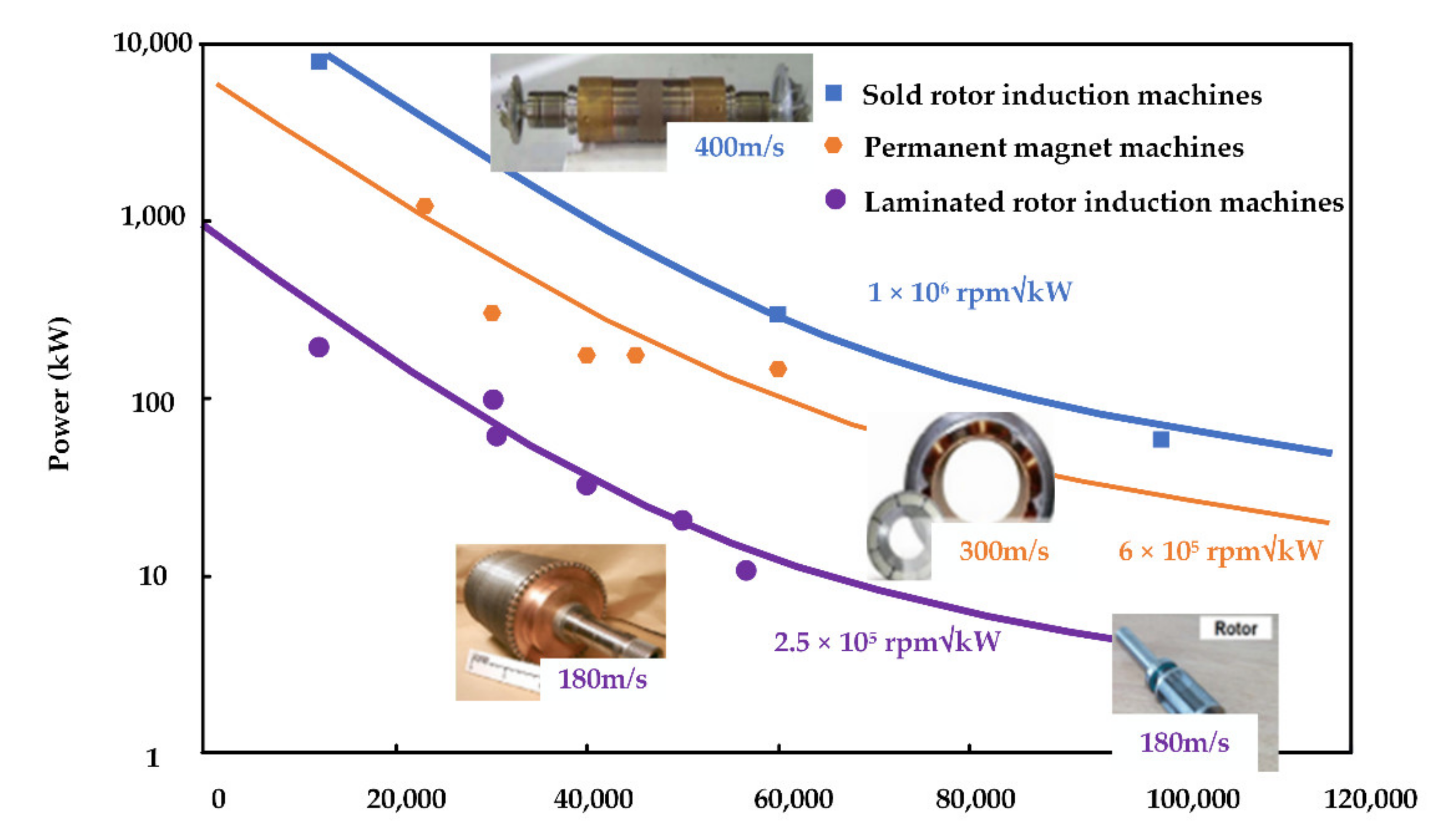
Figure 1 summarizes the previously established limits.
In this figure, the blue line represents the rpm√kW limit line of the solid rotor induction motor, which is approximately 1 × 10
6 rpm√kW. While the solid rotor induction machine achieves the highest power-speed capability, it suffers from comparatively lower efficiencies, due to the high eddy current losses generated within the solid body. While the performance can be improved by using a copper coating on top of the solid body, this also increases the magnetic airgap and hence reduces the power factor. In general, there is a consensus that for many applications, when possible, the use of a squirrel-cage laminated rotor induction machine is preferable due to the higher efficiencies and better power factor [
4,
5]; however, the achievable rpm√kW drops to around 2.5 × 10
5 rpm√kW, highlighted by the purple line in
Figure 1, thus precluding its use for a wide range of applications that require an elevated power and speed rating, such as in the oil–gas industry, compressor markets, as well as within waste heat recovery systems for high horse power internal combustion engines, or other high speed applications that require a wide constant power speed range (CSPR) to be achieved, where the Induction Machine would have considerable system level advantages.
Finally, the third common topology for high-speed applications is the Surface mount Permanent Magnet Machine (SM-PMSM), in which magnets are typically mounted on a solid shaft and retained under compression through the use of a high-strength sleeve typically made of materials such as Inconel, titanium or carbon fiber. In this case, the traditional limit line, shown in orange is about 6 × 10
5 rpm√kW.
Table 1 summarizes the aforesaid limits, as well as the limits of other topologies that have been used for high-speed applications, albeit less frequently.
It should be noted that the limits presented in
Figure 1 and
Table 1 refer to the use of conventional materials. Recently, there have been relevant and interesting material developments both in the field of electrical steels, as well as in the field of copper alloys, with such materials potentially serving as an enabler to push the boundaries for high-speed laminated rotor induction machines. This paper is structured as follows:
Section 2 reviews the developments in high strength copper alloys and electrical steels,
Section 3 describes the multi-domain design considerations of a 150 kW high speed machine for an electrically assisted marine engine turbocharger,
Section 4 discusses the development aspects and finally, the conclusions from this research are presented in
Section 5.
3. The Design of a 150 kW 50 krpm Induction Machine Using Novel Materials
Table 3 summarizes the requirement for the marine engine heat recovery application. The machine is 150 kW, which needs to be achieved over a speed range of 25–50 krpm, thus translating to an rpm√kW of 6 × 10
5. The power-speed requirement derives from the needs of a 3 MW-class marine engine. Engine coolant ethylene-water-glycol (EWG) is available to cool the machine.
At the time of initiating this research, an existing surface PM solution was available, which, although fully functional, makes a difficult case due to the mass (and cost) of the magnets involved, and hence it was desired to move to a magnet-free, induction machine solution. Given that the aim of the application is higher fuel efficiencies, preference was to be made to higher efficiency, laminated rotor solutions if possible. While it is known that with conventional materials such a power–speed combination is outside the operational territory of laminated rotor induction machines, this research investigates as to whether the aforesaid rpm√kW is achievable with the novel high-strength materials described in the previous section.
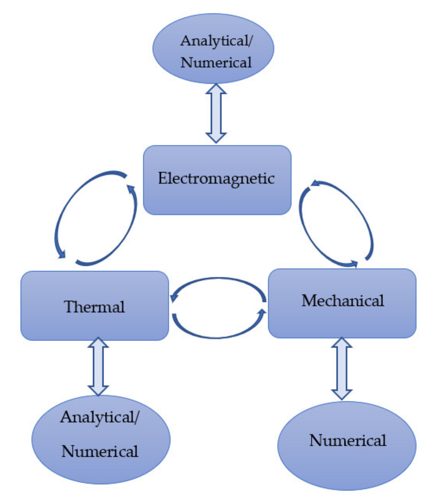
The design of high-speed electrical machines is known to be very challenging due to the close coupling of the sciences involved [
9]. To this end, the use of coupled multi-domain design environments is necessary to achieve a stable design, such as the one used in this investigation, shown in
Figure 5. In this environment, the electromagnetic, thermal and mechanical domains run in parallel so that any geometrical change can be instantly assessed from all the domains. Moreover, comprehensive detailed information about the materials used and their behavior at different temperatures, under different mechanical stresses and different excitations is included within the design environment, as is the information about the various manufacturing techniques.
3.1. Multidomain High-Speed Induction Machine Design Procedure
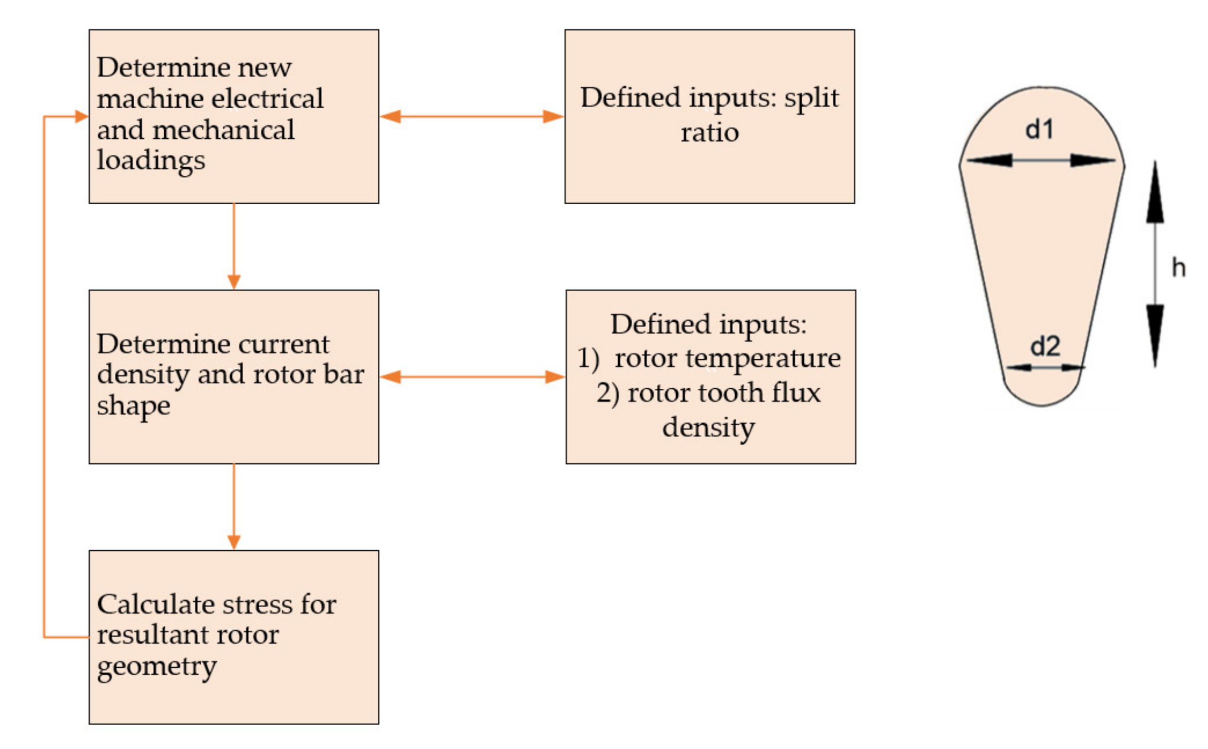
With the electromagnetic, thermal and mechanical domains coupled, the induction machine is designed following the high speed laminated rotor induction machine design procedure described in detail in [
9] and reproduced in
Figure 6. As suggested in the same paper, drop-shaped rotor bars are utilized to maximize the power density while avoiding high stress concentrations on the rotor laminations.
The multi-domain design methodology for maximizing the power density of laminated rotor HSIM (High Speed Induction Machine) is described in
Figure 6. Basically, for each rotor diameter considered, the various combinations of electrical/magnetic loadings, which correspond to the particular diameter, are evaluated. The different electrical/magnetic loadings correspond to different airgap flux-densities, turn number as well as rotor bar current, as described in [
9].
Based on the (i) rotor bar current, (ii) maximum rotor temperature and (iii) a pre-defined flux-density in the rotor teeth, the drop-shaped bar can be automatically sized and the resultant mechanical stress calculated. The procedure is repeated for different rotor diameters, to identify the most feasible rotor design, with reduced stress and an acceptable temperature rise, as one case shown in
Figure 7.
3.2. Mechanical Design Aspects
Since this paper treats the exploitation of novel high-strength materials to increase the power–speed capability of a laminated rotor induction machine, in this section, greater focus is expended on the rotor mechanical design aspects of the machine. Given that the machine targets a very high rpm√kW, the machine is designed using the novel high-strength materials described in
Section 2, but importantly, avoiding any material that uses rare-earth materials such as Cobalt Iron laminations, since this paper aimed to develop a rare-earth-free machine solution.
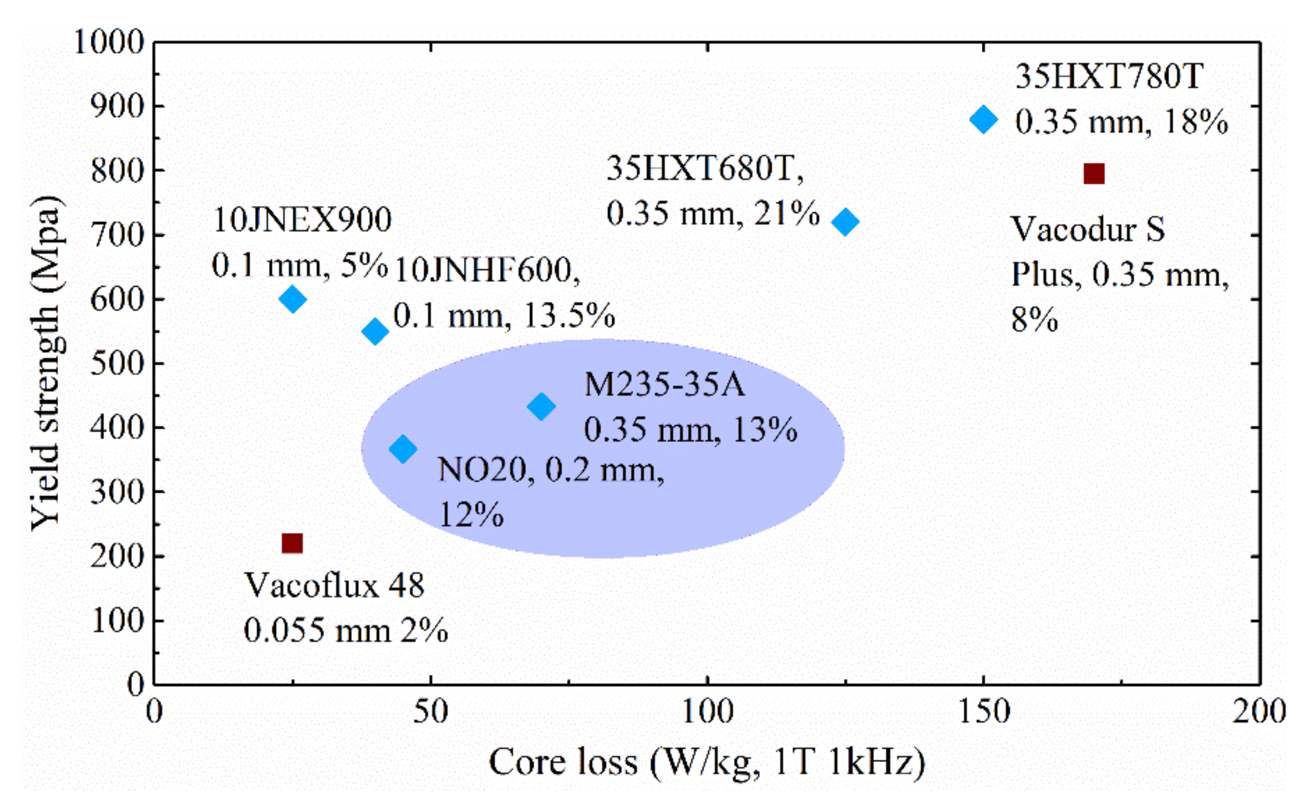
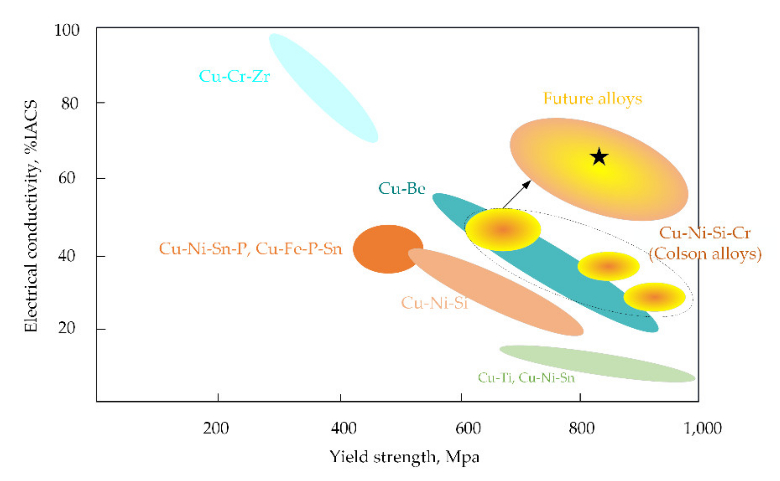
Table 4 summarizes the materials considered, including the high strength HXT780T, which is the best-in-class commercially available high-strength SiFe, with a yield strength of 850 MPa. For the rotor bars, CuCrZr is considered, given its high yield strength (500 MPa) and good conductivity (80% IACS). For the end-rings, where a higher mechanical stress is expected with respect to the bars, the Beryllium-free CuNiSiCr alloy, with a yield strength of 820 MPa and a conductivity of 27% IACS, is considered.
3.2.1. Laminations
The rotor laminations and the rotor end-rings can be simplified as a rotating hollow disk for first-level stress analysis. For a rotating hollow disk, the hoop stress and radial stress distributions can be calculated using the following equations [
10]:
where ‘
σr’ and ‘
σH’ are the stress in the radial and hoop direction of the disk, ‘
A’ and ‘
B’ are constant values at the inner and outer radii of the hollow disk, ‘
ω’ is the rotating speed of the disk, ‘
r’ is the radius of the disk and ‘
v’ and ‘
p’, are the material Poisson ratio and mass-density, respectively, of the material.
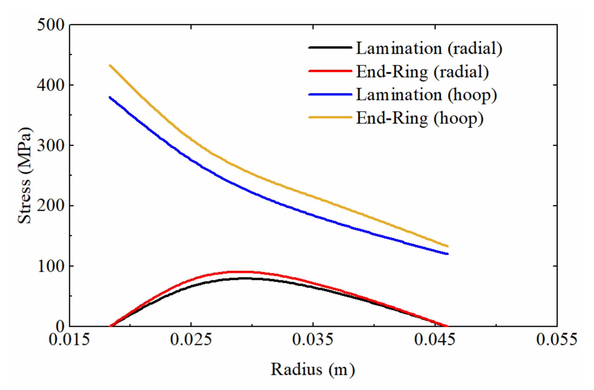
Using the simple hollow disk equations,
Figure 8 shows the stress distribution of the rotor laminations and end-rings at the rotational speed of 50 krpm. As can be seen from the figure, the maximum stress for the lamination is around 400 MPa and occurs at the inner edge of the disk. Due to the different material mass-density and Poisson ratio, the stress at the end-ring inner diameter is slightly higher, around 450 MPa. Importantly, both the initially obtained stress values for the lamination and the end-ring indicate that, at the diameter and speed targeted, the use of special materials with a markedly higher yield strength with respect to the conventional materials is required.
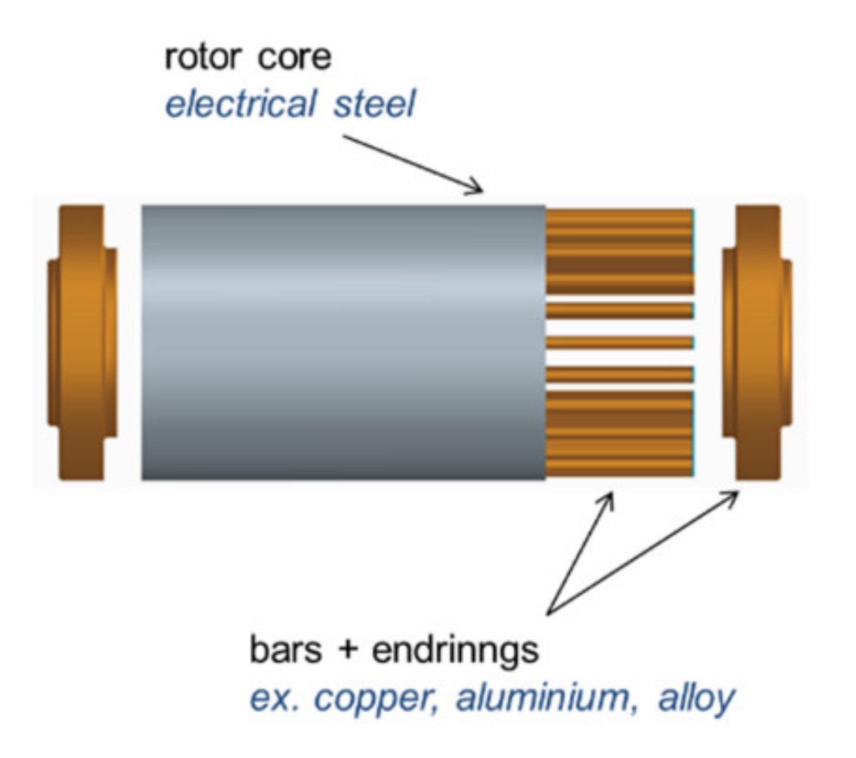
For an Induction Machine’s rotor, the lamination stack also holds the rotor bars. Due to the limited mechanical strength of the long thin bars, the lamination stack provides retaining support against the centrifugal forces of the copper bars in the radial direction. This generates extra stress in the laminate disk, beyond that calculated by simply using Equation (1).
The detailed distribution of stress including the centrifugal load and the load due to the bars is obtained using Finite Element Analysis (FEA).
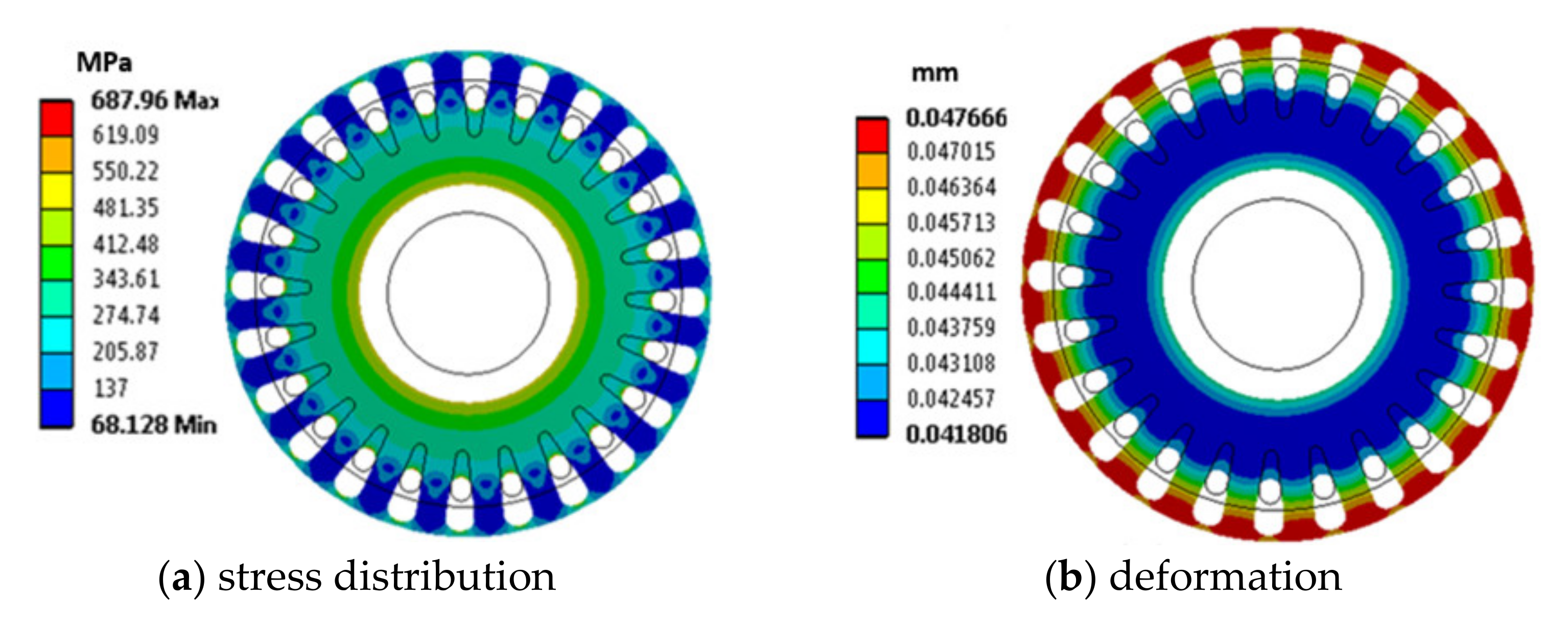
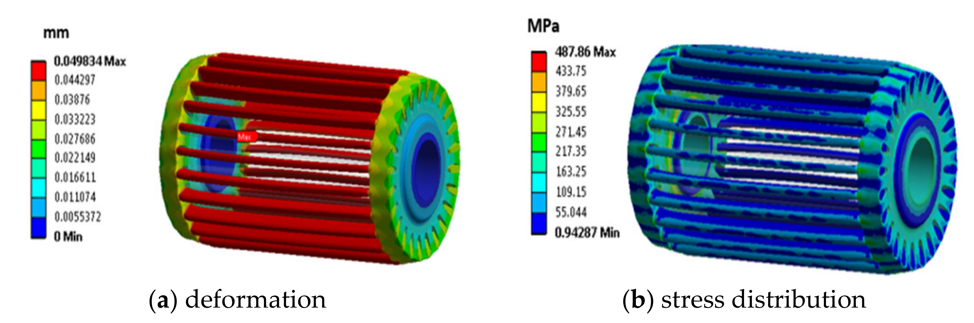
Figure 9a shows the stress distribution of the lamination at 50 krpm. The copper bars’ masses are added to the slots on the laminate disk, which allows the total centrifugal force loads to be simulated. From
Figure 9a it can be observed that the maximum stress in the lamination occurs at the bottom of the slots due to the extra centrifugal loading from the bars and stress concentration at inner corner of opening, which is different compared to the hollow disk where the maximum stress occurs at the inner surface of the disk. The maximum stress in the lamination is 687 MPa, which is an over 75% increase with respect to the hollow disk only, although still below the yield strength of the HXT780T material by over 20%. Moreover, compared to
Figure 8,. the extra load from the rotor bars also significantly increases the stress level at the inner surface of the hollow disk.
Figure 9b shows the deformation of the lamination under rotation. As expected, maximum deformation occurs at the outer surface of the lamination. The radial growth of the lamination at 50 krpm is less than 0.047 mm, which is less than 10% of the airgap of the machine.
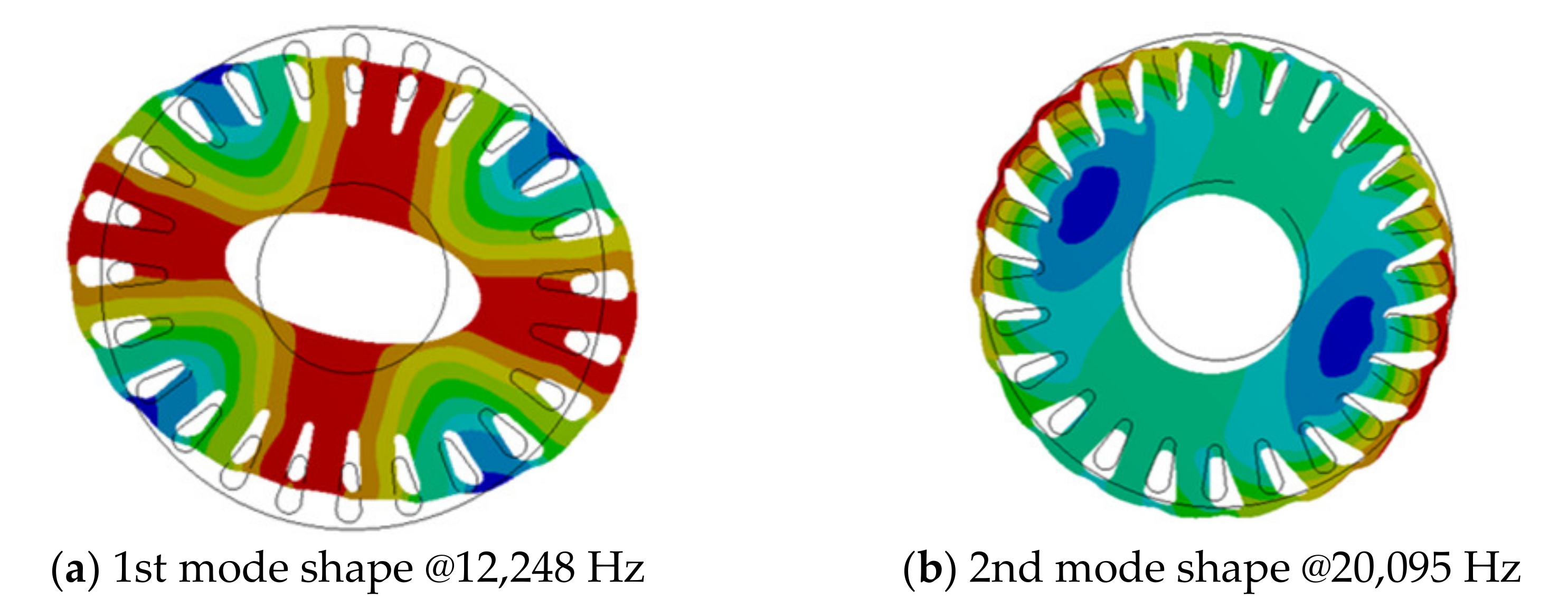
The natural frequencies of the laminations are also predicted using the FEA method.
Figure 10 shows the first and second mode shapes of the laminate disk. The first mode shape occurs at a frequency of 12,248 Hz and is much higher than the machine max operating speed of machine 50 krpm (~833 Hz).
3.2.2. End-Rings
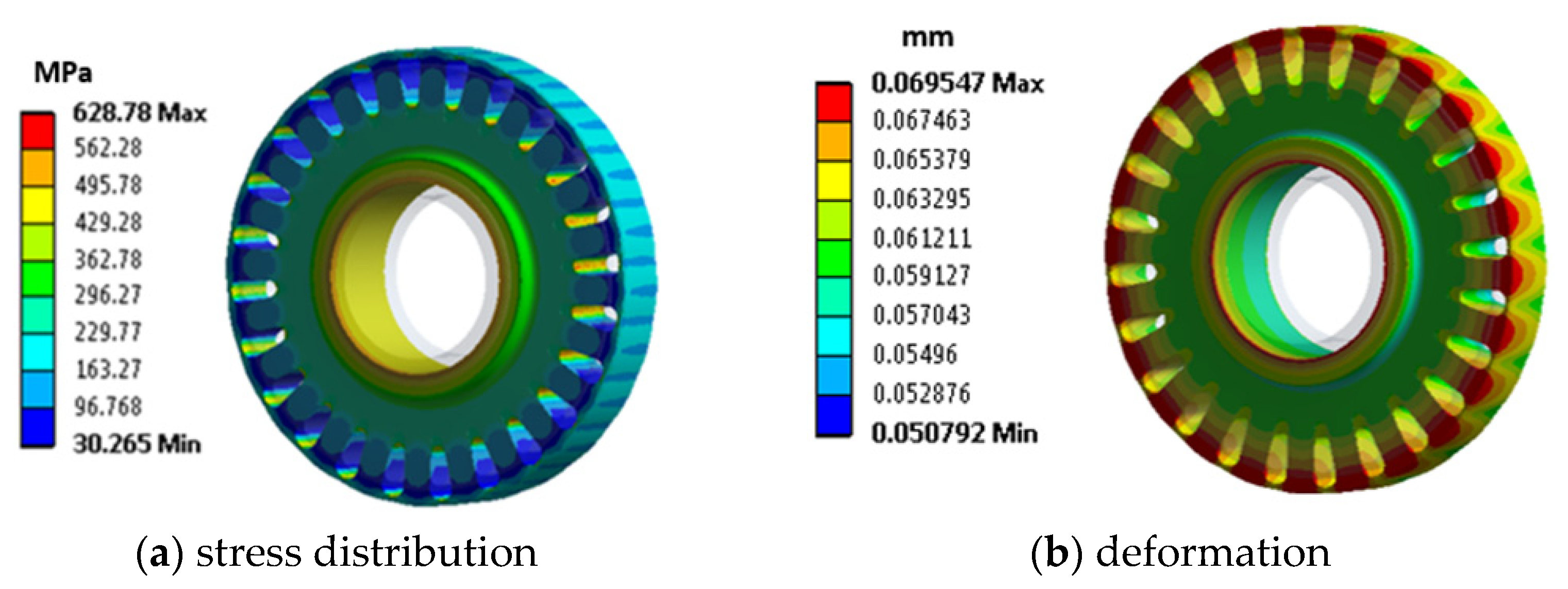
FEA is also used to predict the stress distribution on the CuNiSiCr end-rings when the CuCrZr bars are embedded within.
Figure 11 shows the FEA results of stress and deformation of the disk at 50 krpm. The stress concentrations occur at the location where the bars are inserted with a maximum of 628 MPa, which is 40% higher with respect to the theoretical hollow disk, although still safely below the yield strength of the CuNiSiCr material. The maximum deformation of the disk at 50 krpm is 0.07 mm, as shown in
Figure 9b.
3.2.3. Rotor Bars and Rotor Cage
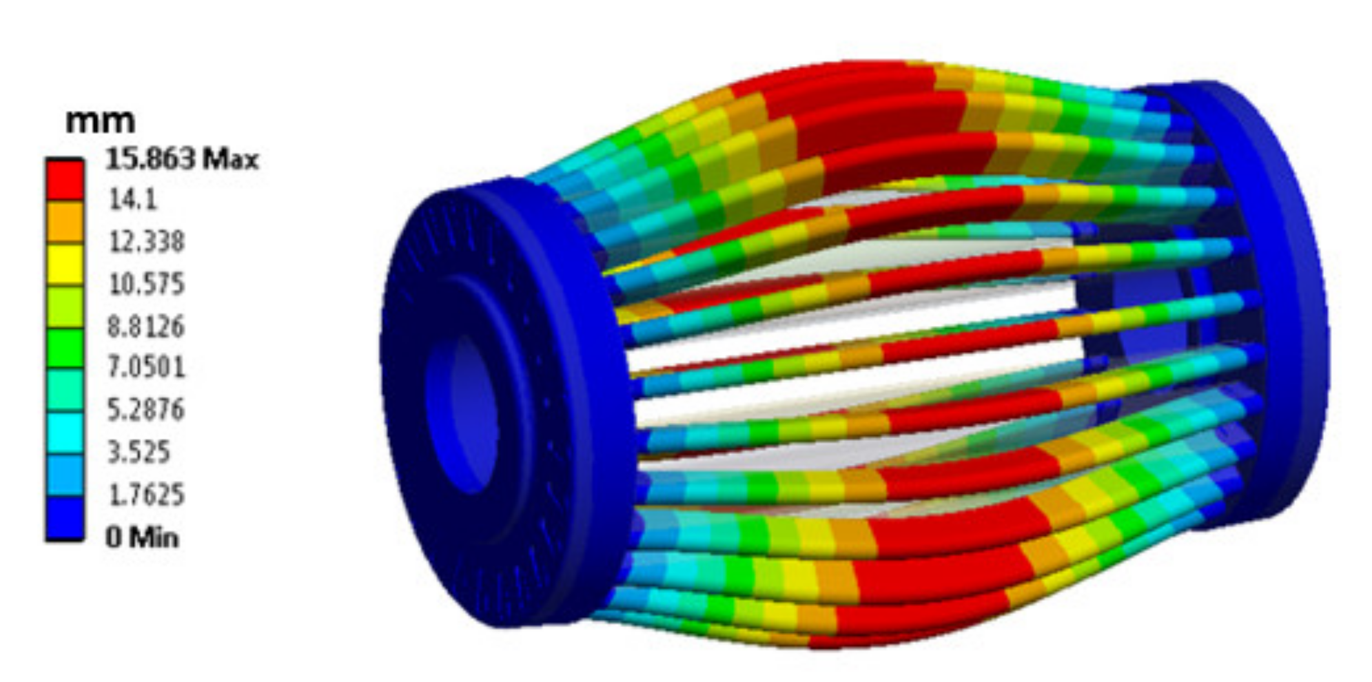
An FEA simulation is carried out to understand the extent of the deformations when the rotor squirrel-cage rotates at 50 krpm, without the support of the laminations. As can be seen from
Figure 12, the deformation of the CuCrZr bars is significantly large if the bars are only supported by the two end disks, under which circumstance the stress in the bar would well exceed the limitations of the material. However, for an induction machine rotor, all the conductors are inserted into the rotor lamination stack that supports the conductors, as shown earlier in
Figure 7, and hence limits their deformation. The maximum deformation of lamination (0.05 mm, as determined from
Figure 9), is applied as a boundary condition to the copper cage, as shown in
Figure 13, in which case the maximum stress of the bar will be limited to around 400 MPa, yielding a mechanical design margin of 1.2.
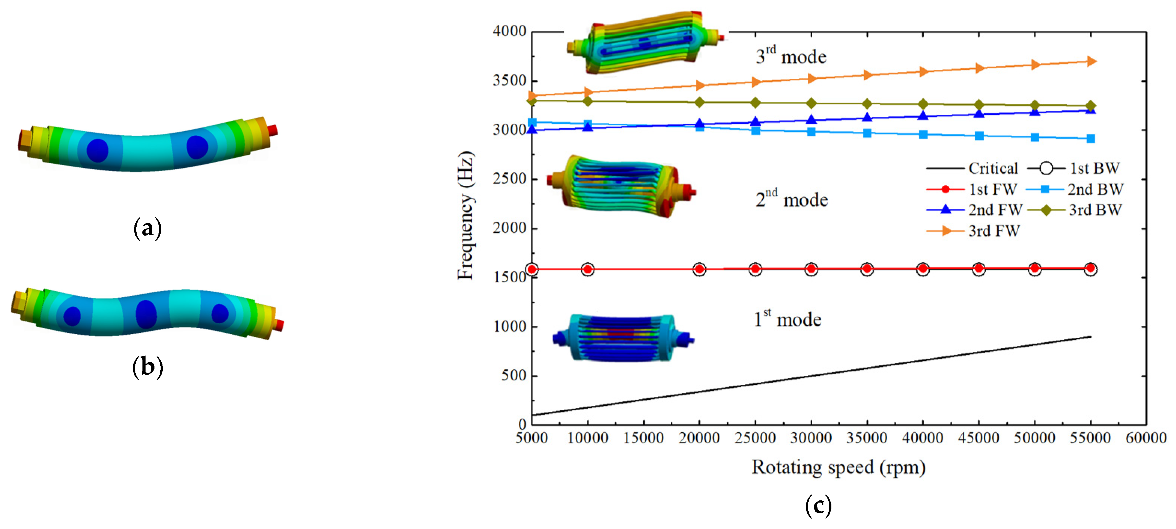
3.2.4. Rotor Dynamics
In the first instance, the shaft itself is analyzed without the influence of the rotor core and the rotor cage. The first and second bending modes occur at the frequencies of 2839.9 and 7086.4 Hz, respectively, well above the machine operating frequency of 833.3 Hz. When the mass of the rotor laminations, copper-alloy bars and the two end-disks are added to the shaft, the natural frequency corresponding to the first bending mode drops to 1565.9 Hz, while the second bending mode frequency drops to 3563.8 Hz, as shown in
Figure 14a,b.
For more accurate analysis, the rotor assembly includes the shaft and the rotor cage. In this case, the cage, made of high-strength materials, apart from the well-known primary electromagnetic design function of generating torque, also serves an important mechanical design function of stiffening the rotor assembly.
4. 150 kW 50 krpm Induction Machine Development Aspects
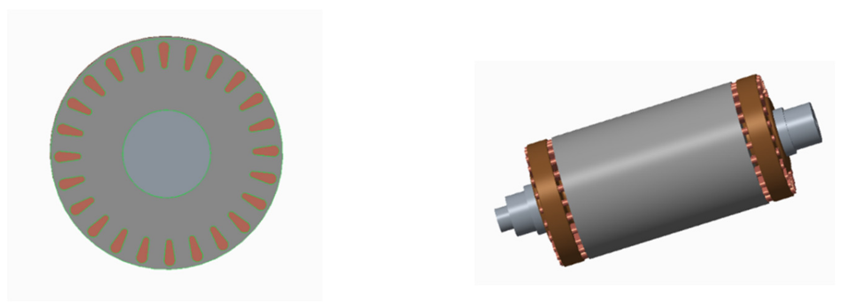
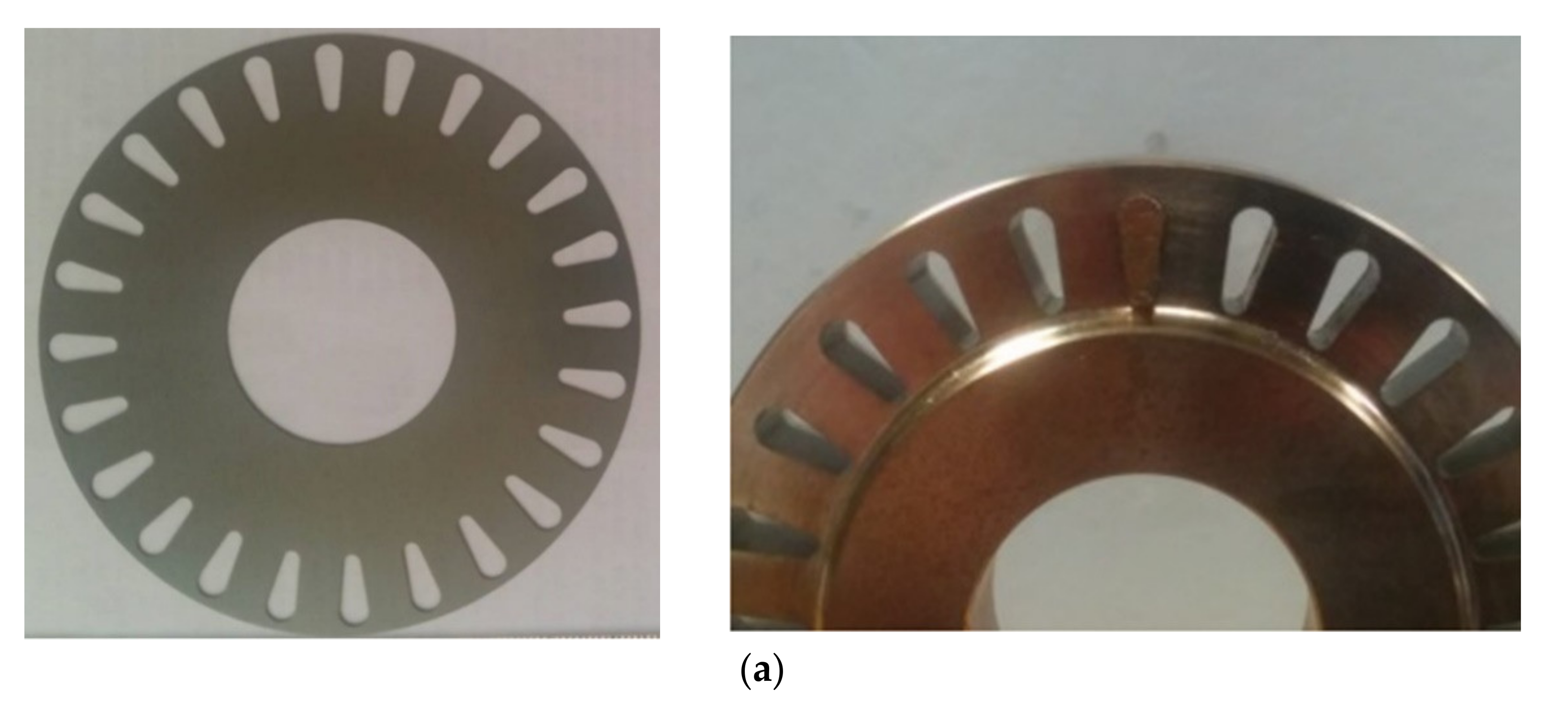
With the geometry and mechanical aspects considered, the machine is prototyped using the high strength materials. Due to low prototype volumes, the HXT780T laminations are laser cut from loose laminations. Similarly, the rotor bars and end-rings are wire-cut from solid CuCrZr and CuNiSiCr billets. For volume production, a punching tool can be used for the high strength laminations, while the alloys used for the rotor cage can be conveniently cast, or for the case of the rotor-bars an extrusion process can also be used. The cut laminations, rotor bars and end-rings are shown in
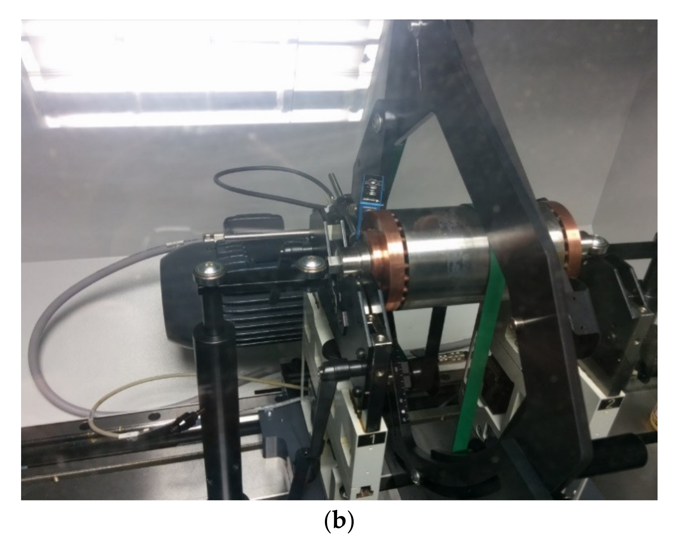
Figure 15a. The bars are then inserted into the lamination stack and brazed using a high conductivity alloy. The rotor is then precision balanced for high-speed operation, as shown in
Figure 15b.
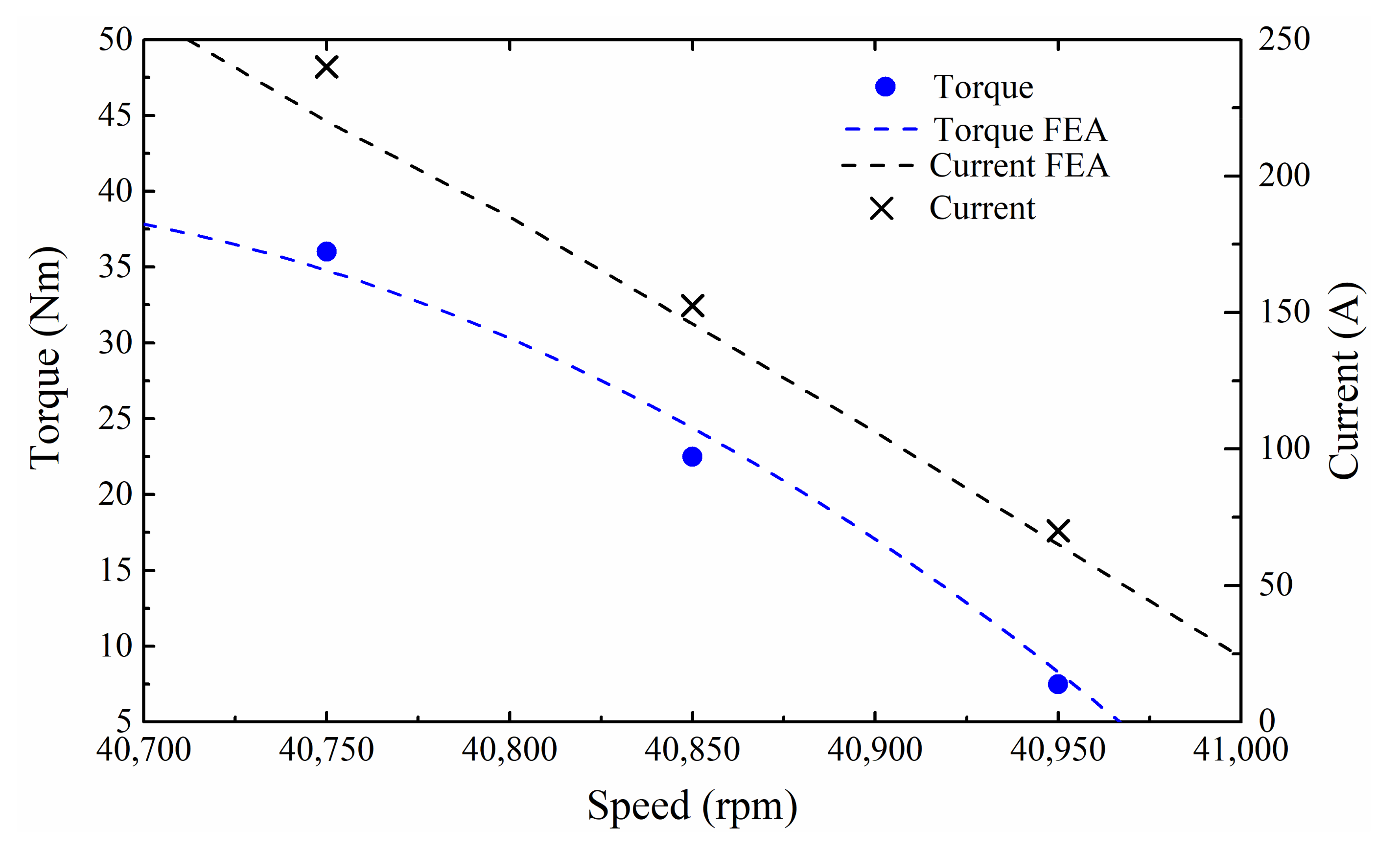
Characterization is performed on a high-speed dynamometer in order to check the performance on-load. In
Figure 16, the current and torque are compared to the FEA predictions at a frequent high-speed operation point of 40 krpm. For a given speed, the maximum difference to the predicted current is 11%.
5. Conclusions
With the increasing drive to achieve higher power densities, the research, development and commercialization of such machines is at an all-time high. While the laminated rotor induction machine is a long-established, mature technology, it can sometimes be overlooked for higher power–speed product applications, as the achievable power–speed capability and peripheral speeds are traditionally lower with respect to those attained by the more common surface-PM topologies.
Recent developments in the IM’s constituent materials include the development of environmentally friendly Be-free high-strength copper alloys and high-strength electrical steels, with yield strengths in excess of 800 MPa, around twice that of conventional steel.
This paper has described the mechanical design procedure for high-speed IMs, which can be summarized as:
Start with an analytical calculation of stress in the lamination and end-ring at the maximum speed, assuming a circular hollow disk (no slots present) as the initial design.
Complete detailed FEA analysis of the stress distribution and deformation for rotating laminations and end-rings including all the geometric features to guarantee a safety margin of mechanical strength even at the location where stress concentration occurs.
Check the dynamic performances of the rotor at various conditions to ensure the critical speed is well above the machine operating speed.
By using the above mechanical design procedure within a multi-domain environment, and then exploiting the properties of the aforesaid novel electrical steels and copper alloys, this paper has shown that the laminated rotor IM can achieve higher rpm√kW, similar to that typically associated with the SPM technology. This is an important result that can translate to an increase market uptake of high-power, high-speed drives, especially in applications where the mass (and cost) of rare-earths in SPM machines remains prohibitive, such as in waste heat recovery systems of high-horsepower engines.


 ,
, 


