
Low-Voltage, High-Frequency Synchronous Motor for Aerospace Applications
 and
and
Abstract
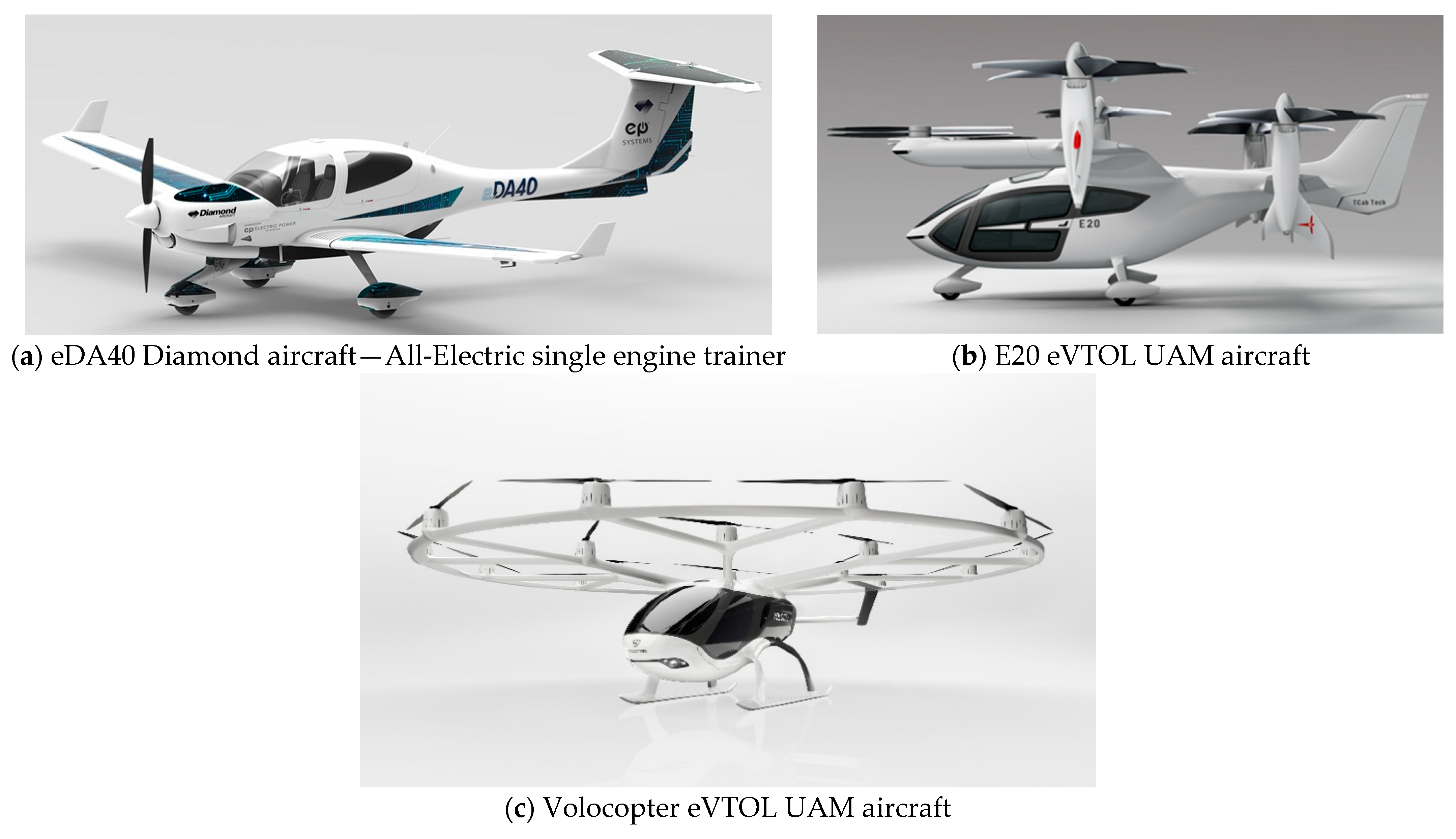
:1. Introduction
2. Description of the Developed Concept
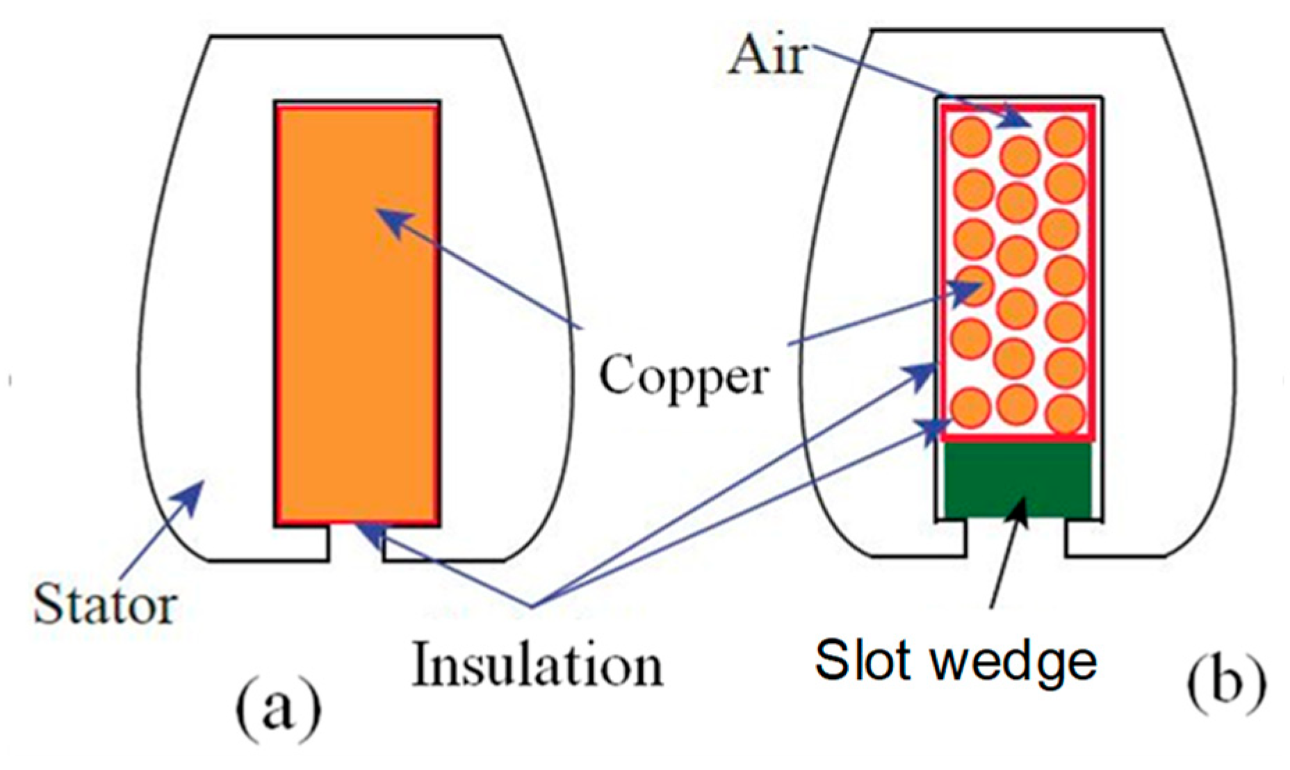
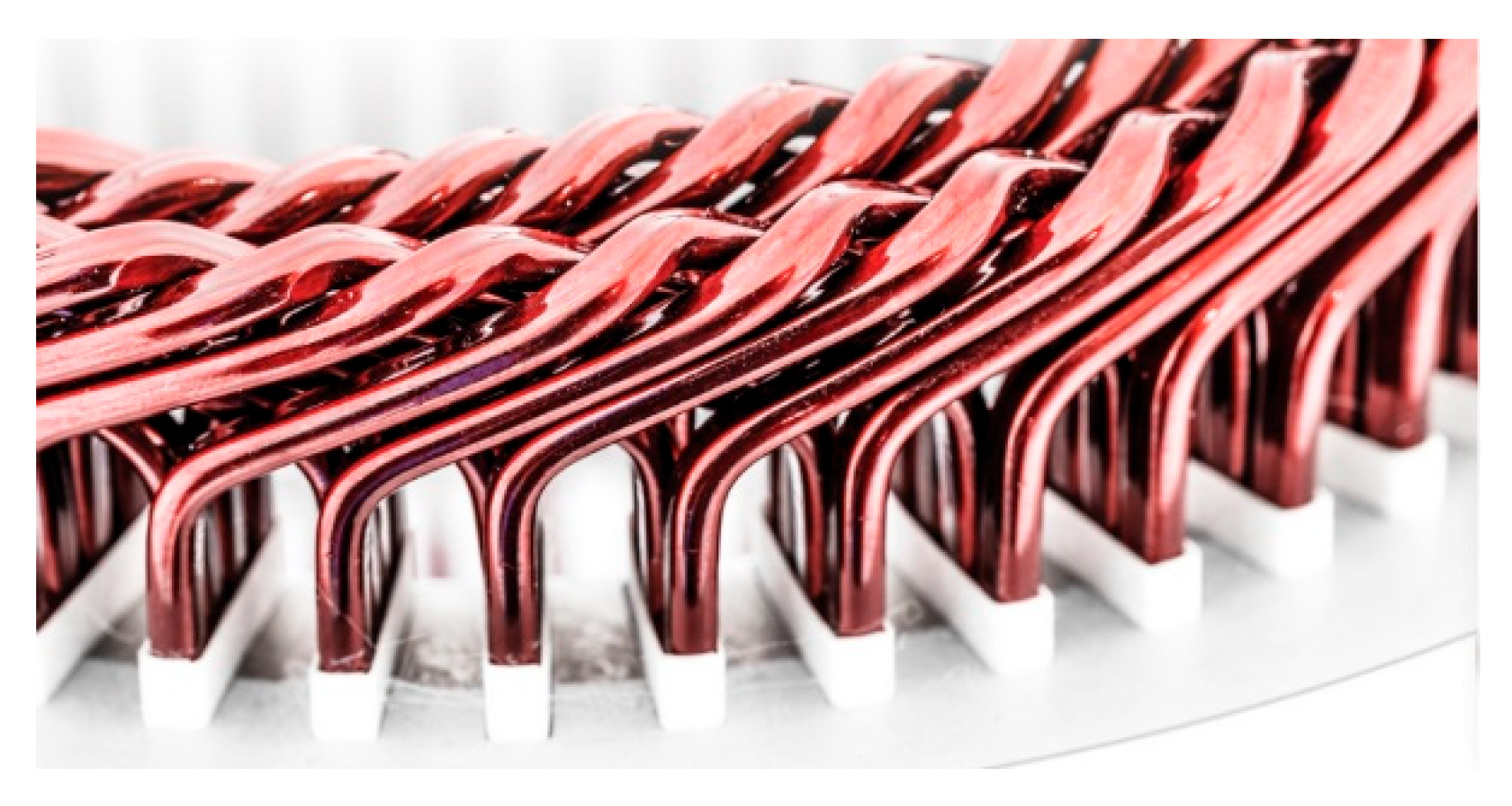
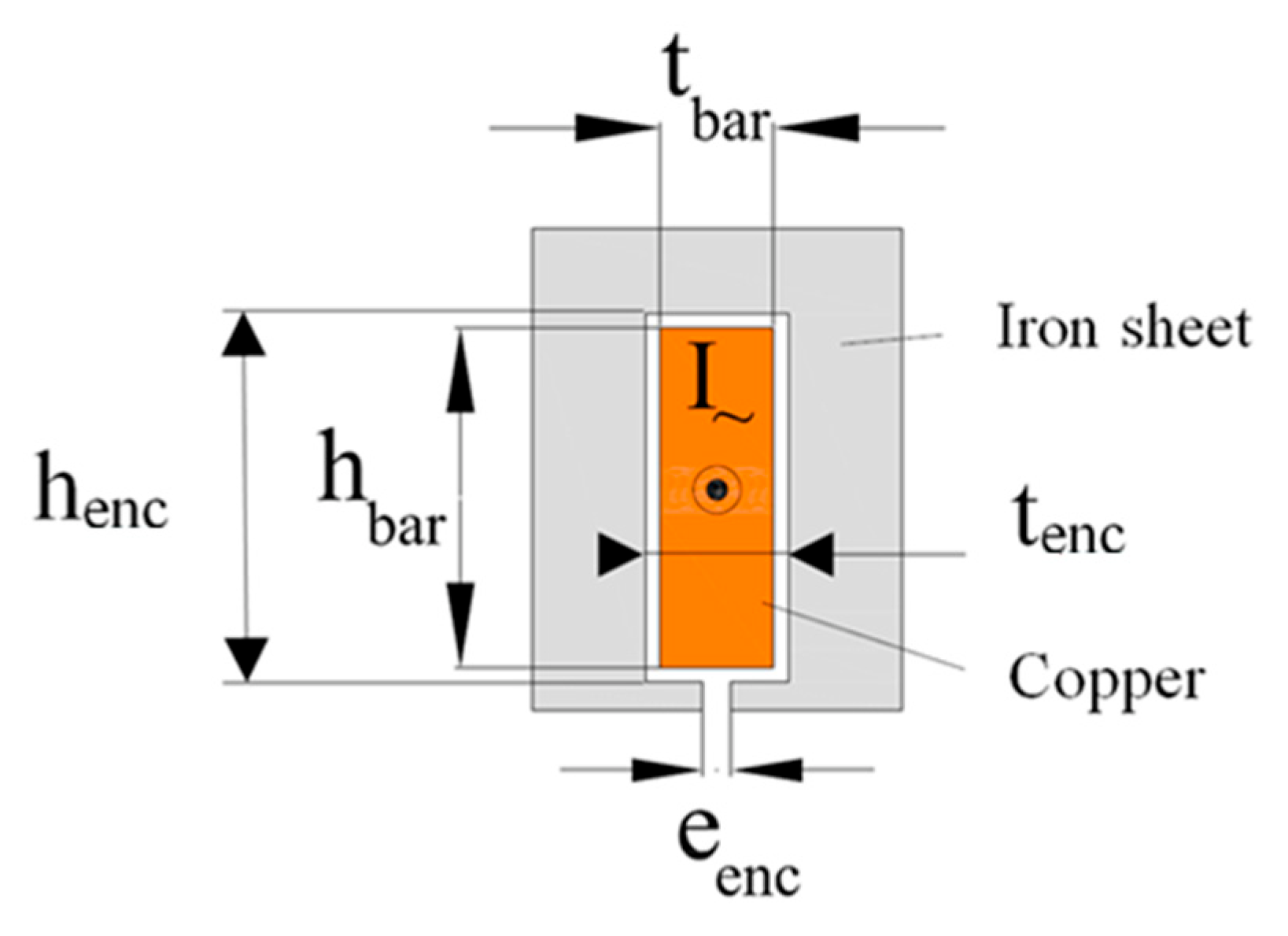
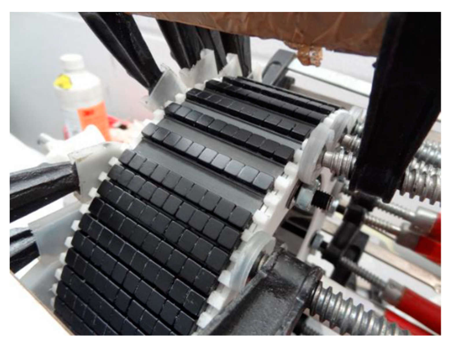
2.1. Solid Bar Winding
- High copper fill factor of 80%, instead of 30 to 40% maximum with a conventional winding.
- The iron-copper thermal resistance is reduced.
- The slot’s opening width can be very narrow (approximately 0.5 mm) resulting in the increase of the flux density in the air gap (more torque output), decrease of the cogging torque/torque ripple, and reduction of AC copper loss due to the rotating magnets.
- The copper overhangs are very compact and well-controlled; this aspect will be further developed in this article.
- The winding manufacturing process is simplified and can be easily automated.
- The machine is more robust and reliable by tremendously reducing the likelihood of the occurrence of short-circuits between phases.
- The solution does not work for a low number of slots unless the motor is operating at a very low voltage.
- The solution does not benefit from the already well-established manufacturing processes and requires new tools and processes.
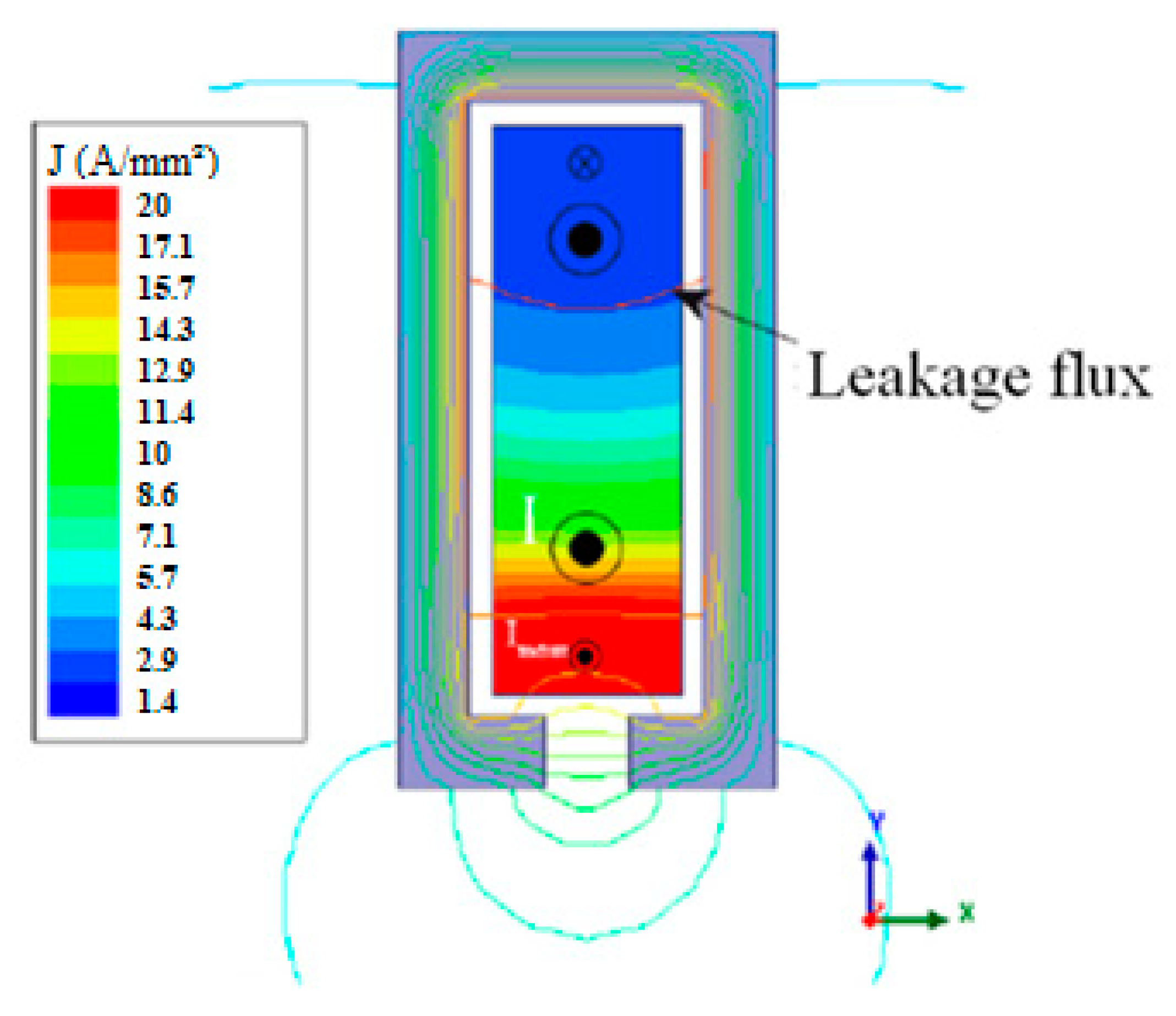
- The main drawback is the excessive loss due to the nature of the solid conductor that is more prone to the AC copper loss. The latter can be fully controlled if the phenomena causing the losses are well-understood. These phenomena are well-studied in the bibliographic references [1,2,3,4,5,6,7,8,9,10], where the main principles will be recalled here without getting into details.
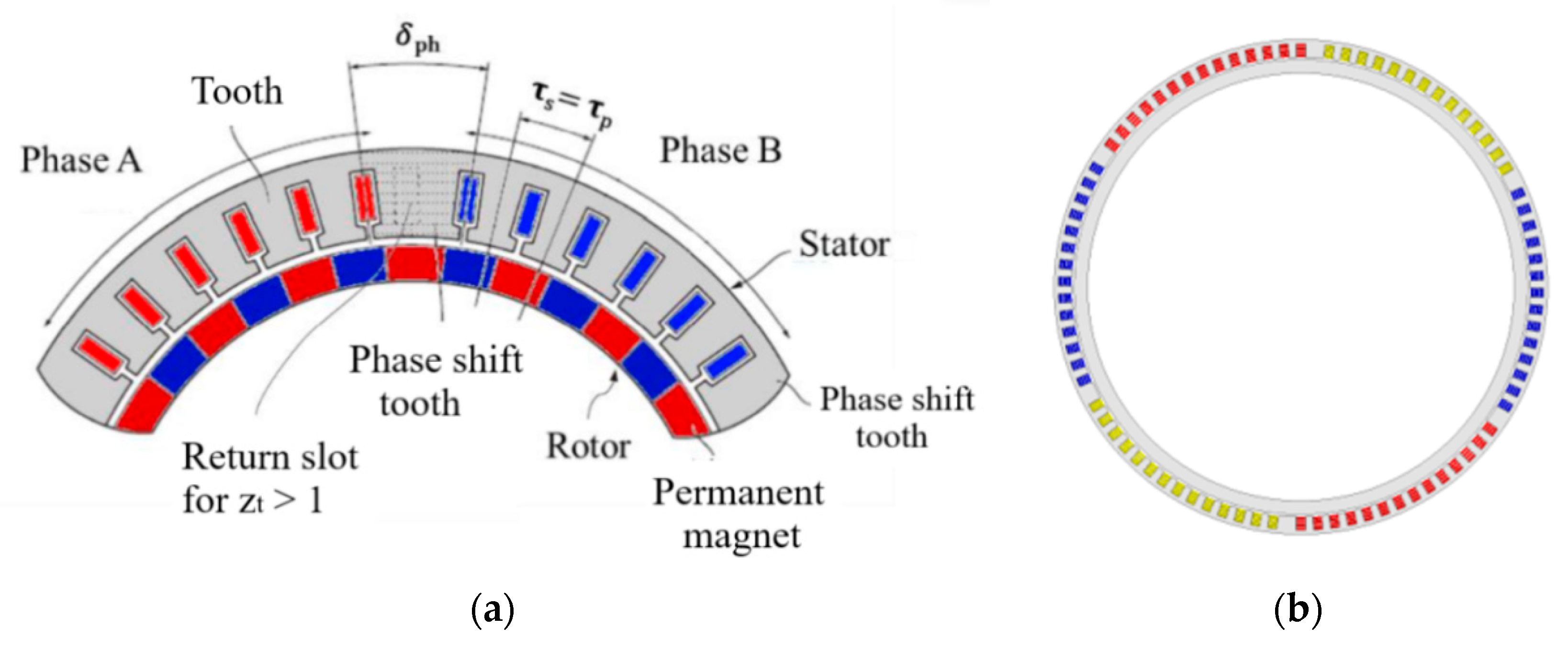
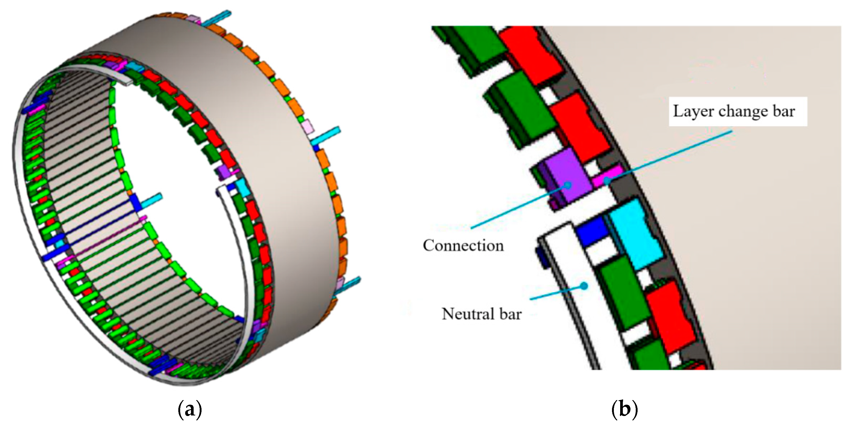
2.2. General Architecture of the Motor and Winding Selection
3. Design/Sizing of the Prototype and Material Selection
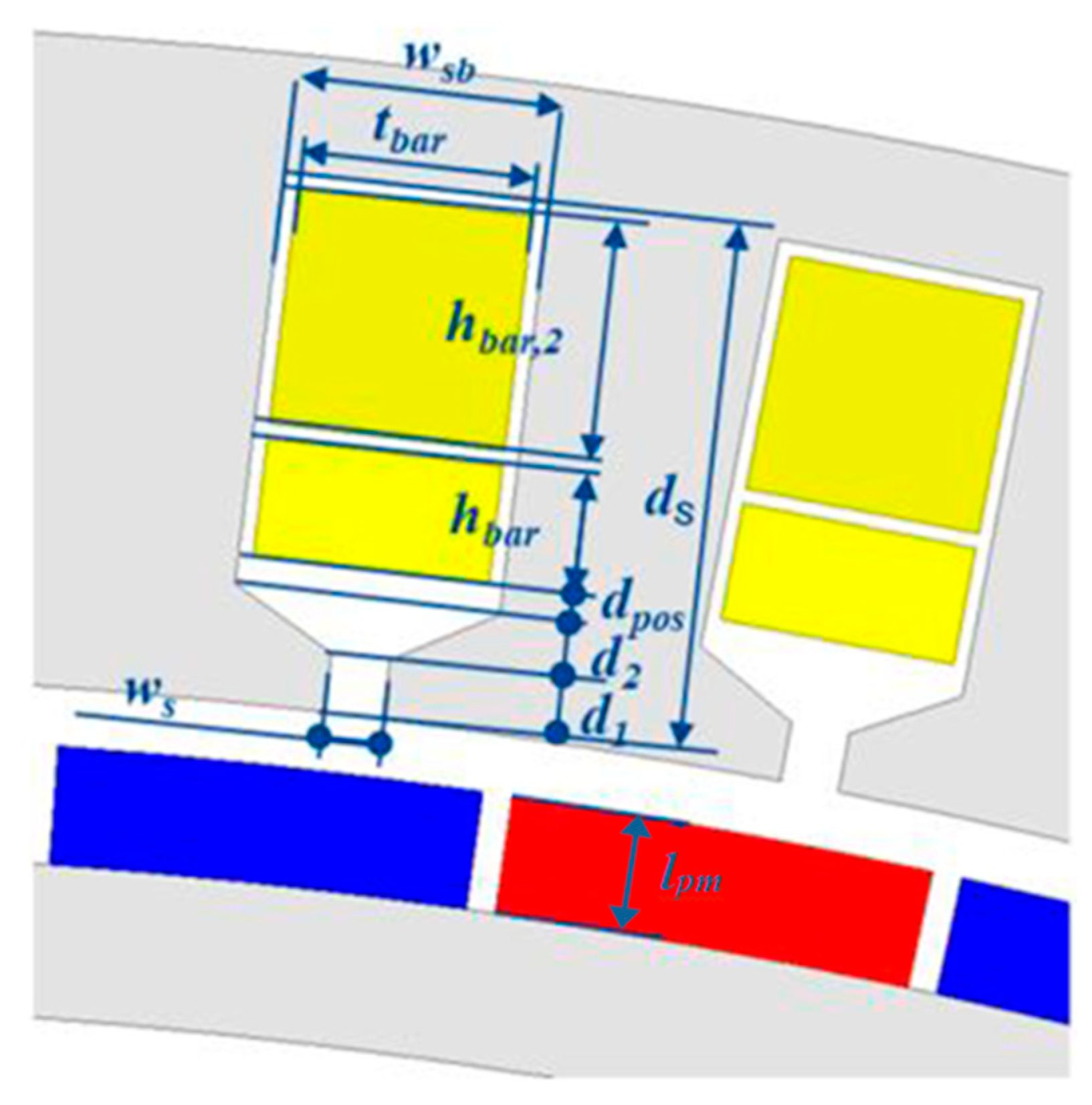
3.1. Electromagnetic Design
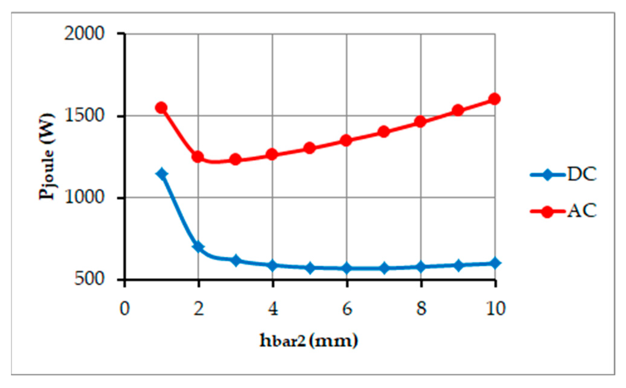
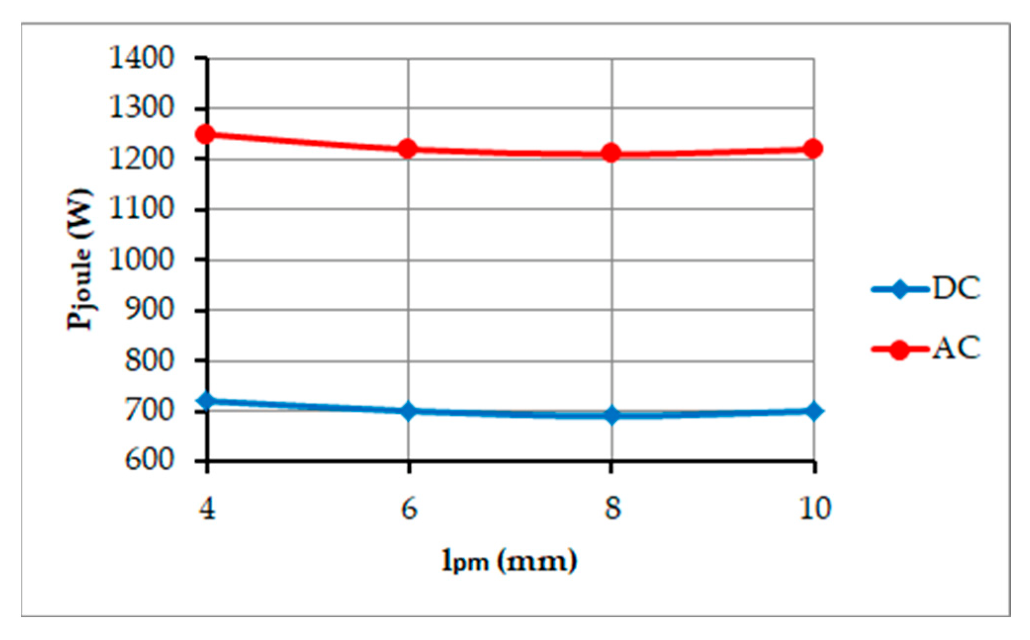
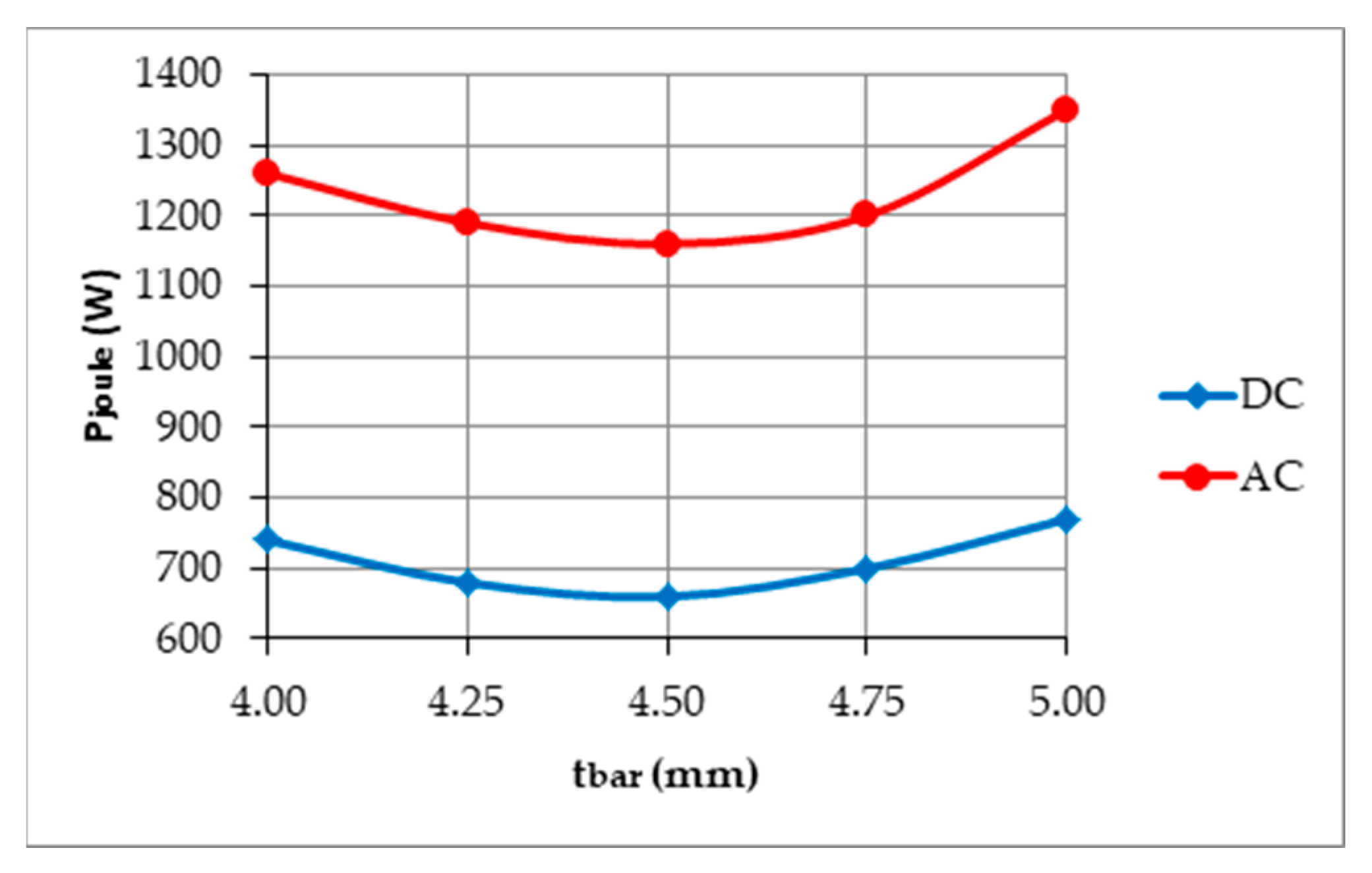
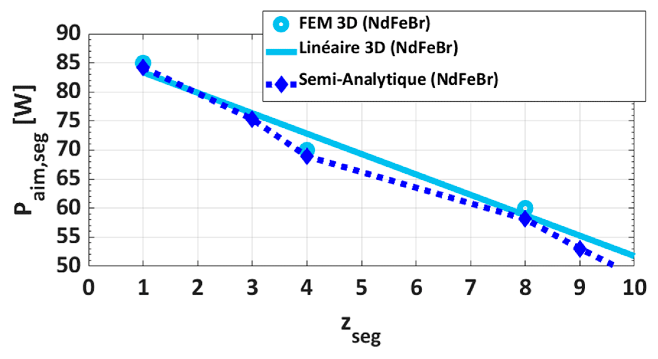
3.2. Simplified Parametric Study
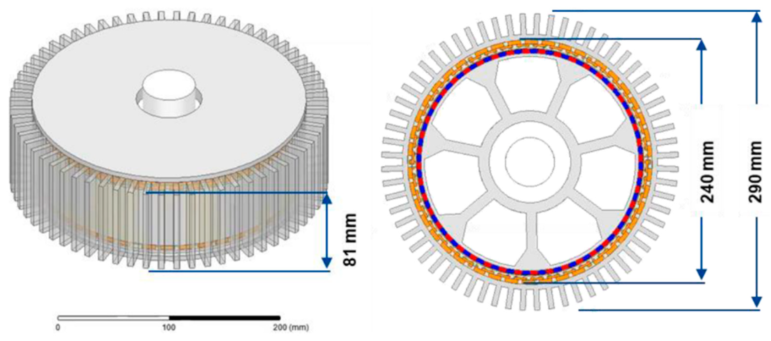
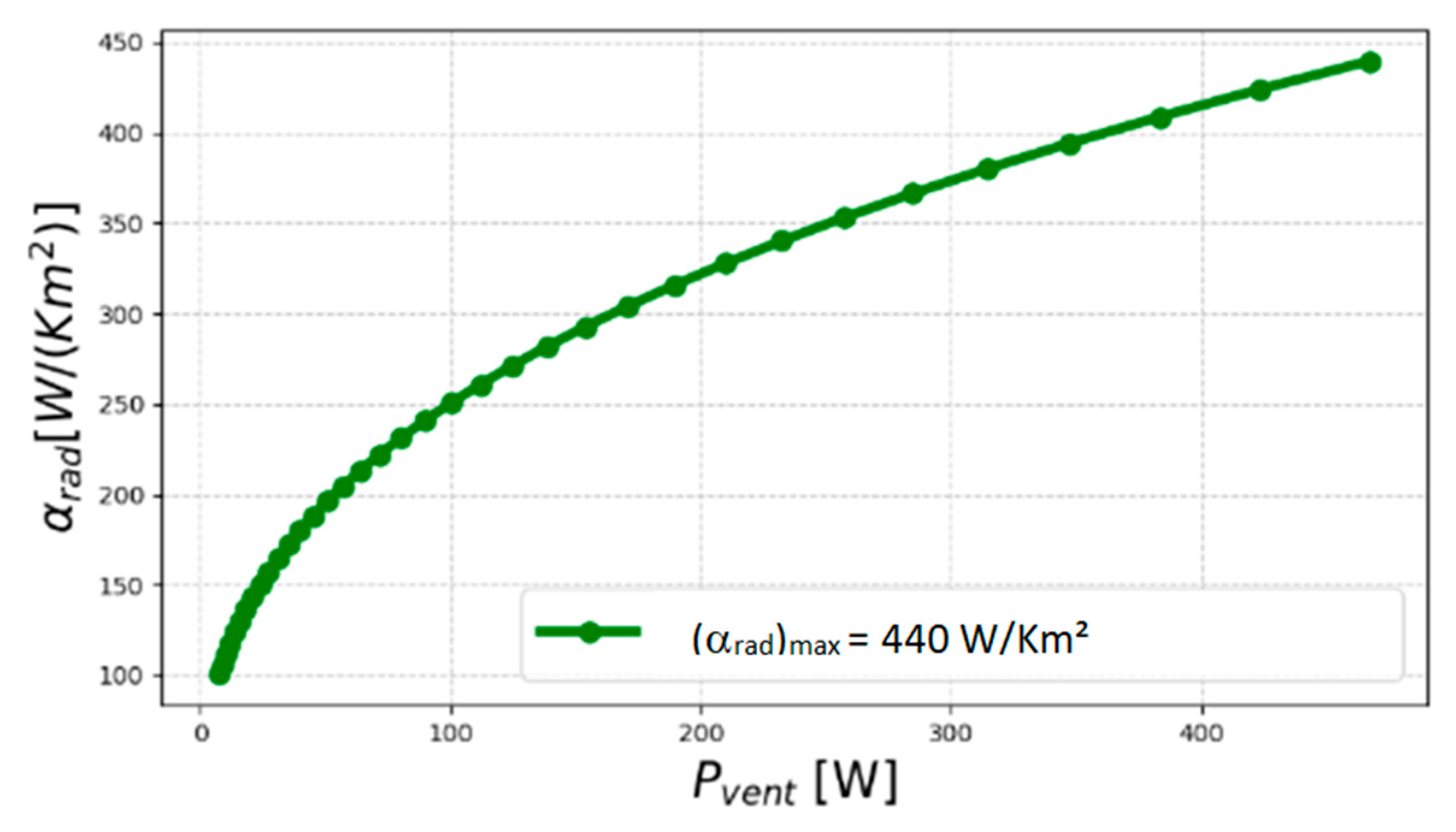
3.3. Materials Selection and Dimensions of the Prototype
4. Experimental Test Results, Performance of the Prototype and Conclusions
Author Contributions
Funding
Institutional Review Board Statement
Informed Consent Statement
Data Availability Statement
Conflicts of Interest
References
- Piscini, L. Study of a High Frequency and High Performance Machine for an Aeronautical Application. Ph.D. Thesis, University of Montpellier, Montpellier, France, 2020. [Google Scholar]
- Boubaker, N. Study of Atypical Losses in High Performance Permanent-Magnet Synchronous Machines for Aircraft Applications. Ph.D. Thesis, University of Montpellier, Montpellier, France, 2016. [Google Scholar]
- Matt, D.; Boubaker, N. Very Low Voltage and High Efficiency Motorisation for Electric Vehicles. In Emerging Electric Machines—Advances, Perspectives and Applications; IntechOpen: London, UK, 2021; ISBN 978-1-83968-732-7. [Google Scholar] [CrossRef]
- Deshpande, Y.B.; Toliyat, H.A.; Nair, S.S.; Dhinagar, S.J.; Immady-Setty, S.; Nalakhat, S. High-torque-density single tooth-wound bar conductor permanent-magnet motor for electric two wheeler application. IEEE Trans. Ind. Appl. 2014, 51, 2123–2135. [Google Scholar] [CrossRef]
- Endert, F.; Heidrich, T.; Möckel, A. Increased power density of permanent magnet synchronous machines by use of concentrated bar windings. In Proceedings of the 2012 2nd International Electric Drives Production Conference (EDPC), Nuremberg, Germany, 15–18 October 2012. [Google Scholar]
- Endert, F.; Heidrich, T.; Schwalbe, U.; Szalai, T.; Ivanov, S.D. Effects of current displacement in a PMSM traction drive with single turn coils. In Proceedings of the Electric Machines & Drives Conference, Chicago, IL, USA, 12–15 May 2013; pp. 160–165. [Google Scholar]
- Levasseur, A. Nouvelles formules, valables à toutes les fréquences, pour le calcul rapide de l’effet Kelvin. J. Phys. Radium 1930, 1, 93–98. [Google Scholar] [CrossRef]
- Liwschitz, M. Calcul des Machines Électriques; SPES: Oakland, CA, USA, 1967. [Google Scholar]
- Zhang, W.; Jahns, T.M. Analytical 2-D slot model for predicting AC losses in bar-wound machine windings due to armature reaction. In Proceedings of the 2014 IEEE Transportation Electrification Conference and Expo (ITEC), Dearborn, MI, USA, 15–18 June 2014; pp. 1–6. [Google Scholar]
- Pyrhonen, J.; Jokinen, T.; Hrabovcova, V. Design of Rotating Electrical Machines, 2nd ed.; John and Wiley and Sons: Hoboken, NJ, USA, 2013. [Google Scholar]
- Boubaker, N.; Matt, D.; Nierlich, F. A Stator Winding Arrangement. Patent WO2020208425A1, 15 October 2020. [Google Scholar]


| Parameter | Value |
|---|---|
| Maximum continuous power @ 2500 RPM | 42 kW |
| Nominal output torque | 160 Nm |
| Transient power @ 2800 RPM (for max duration of 30 s) | 60 kW |
| VDC voltage supply (battery) | 300 VDC |
| Maximum overall outer diameter including housing fins | 290 mm |
| Maximum rotor inertia | 0.03 kg m2 |
| Maximum length of the wound stator core pack | 75 mm |
| External air flow for cooling | 200 L/s |
| Minimum efficiency | 92% |
| Configuration | I | II | III |
|---|---|---|---|
| Magnets grade | N45UH | N45UH | Sm2Co17 (Br = 1.1 T) |
| Rotor material | Vacoflux50® | Aluminium | Aluminium |
| Tmagnet (°C) | 76 | 88 | 124 |
| Twinding (°C) | 100 | 122 | 201 |
| Trotor (°C) | 76 | 88 | 124 |
| Tstator (°C) | 98 | 120 | 167 |
| Phase current (Arms) | 185 | 225 | 288 |
| Total losses (kW) | 2.2 | 2.75 | 4.56 |
| Efficiency (%) | 94 | 92 | 88 |
| Torque (Nm) | 133 | 128 | 143 |
| Performance | Steady-State Temperatures | ||
|---|---|---|---|
| Phase current (Arms) | 253 | Tmagnet (°C) | 108 |
| Back EMF constant Ke (Vs/rad) @ 20 °C | 0.29 | Twinding (°C) | 152 |
| Total losses (kW) | 4.2 | Trotor (°C) | 112 |
| Efficiency (%) | 90 | Tstator (°C) | 148 |
| Torque (Nm) | 160 | ||
| Nominal output torque | 160 NM |
| Maximum continuous power @ 2500 RPM | 42 kW |
| Nominal efficiency | 90% |
| Overall outer diameter | 290 mm |
| Total length | 92 mm |
| Total mass/active mass | 9.7 kg/5.7 kg |
| Power-to-weight ratio, total/active | 4.3 kW/kg/7.4 kW/kg |
| Torque-to-weight ratio, total/active | 16.5 Nm/kg/28 Nm/kg |
| Back EMF constant Ke (phase to neutral RMS) @ 20 °C | 0.26 Vs/rd |
| Torque constant Kt @ 20 °C | 0.78 Nm/Arms |
| Phase resistance @ 100 °C | 12.4 mΩ |
| Phase inductance | 16.4 μH |
| No-load core losses @ 2500 rpm | 900 W |
Publisher’s Note: MDPI stays neutral with regard to jurisdictional claims in published maps and institutional affiliations. |
© 2022 by the authors. Licensee MDPI, Basel, Switzerland. This article is an open access article distributed under the terms and conditions of the Creative Commons Attribution (CC BY) license (https://creativecommons.org/licenses/by/4.0/).
Share and Cite
Matt, D.; Piscini, L.; Boubaker, N.; Gimeno, A.; Enrici, P.; Aitakkache, M. Low-Voltage, High-Frequency Synchronous Motor for Aerospace Applications. Electronics 2022, 11, 2719. https://doi.org/10.3390/electronics11172719
Matt D, Piscini L, Boubaker N, Gimeno A, Enrici P, Aitakkache M. Low-Voltage, High-Frequency Synchronous Motor for Aerospace Applications. Electronics. 2022; 11(17):2719. https://doi.org/10.3390/electronics11172719
Chicago/Turabian StyleMatt, Daniel, Lorenzo Piscini, Nadhem Boubaker, Anthony Gimeno, Philippe Enrici, and Mourad Aitakkache. 2022. "Low-Voltage, High-Frequency Synchronous Motor for Aerospace Applications" Electronics 11, no. 17: 2719. https://doi.org/10.3390/electronics11172719