Article

A Compact Low-Profile Antenna for Millimeter-Wave 5G Mobile Phones

1
School of Electrical Engineering and Computer Science, National University of Sciences and Technology, Islamabad 44000, Pakistan
2
College of Engineering, Taibah University, Madinah P.O. Box 344, Saudi Arabia
3
Department of Electronics Engineering, University of Engineering and Technology, Taxila 47050, Pakistan
*
Author to whom correspondence should be addressed.
Electronics 2022, 11(19), 3256; https://doi.org/10.3390/electronics11193256
Submission received: 6 August 2022 / Revised: 28 September 2022 / Accepted: 29 September 2022 / Published: 10 October 2022
(This article belongs to the Special Issue Advances in Micro/mm Waves Circuits and Antennas)

Abstract

:
This paper presents a very low profile and simple antenna design for dual beam and dual-band operation to be employed in future 5G mobile phones operating in the millimeter-wave bands of 26.75–30.31 and 35.83–41.22 GHz. The two distinct resonances at 28 and 38 GHz are achieved using a meta-material-based structure consisting of a closed-ring resonator (CRR) and a split-ring resonator (SRR) by co-centrically combining two planar hexagonal rings; i.e., an inner split-ring resonator (SRR) and an outer closed-ring resonator (CRR). The antenna has a high gain of 4.5 dBi. The antenna also exhibits a dual-beam radiation pattern in one of its planes. The overall antenna size is 6 × 8 mm2 and is manufactured using a low-cost PCB fabrication process. The antenna’s dual-beam operation, broadband characteristics, high gain, and low profile makes it a potential candidate for future millimeter-wave mobile phones, especially in applications where space diversity is required.

1. Introduction

Future mobile service operators will face the problem of providing an extremely large bandwidth to allow an enormous number of mobile users to connect to each other via social media networks. To cope with this problem, the International Telecommunication Union (ITU) is planning to allocate the spectrum between 24 and 86 GHz for mobile services [1]. Future mobile systems will have extremely high data-rate communication in the range of 5–50 Gbps. These high data rates will only be possible with communication in the millimeter-wave frequency bands. Reliability verification of millimeter-wave communication for mobile phones in dense urban scenarios has been performed and it was found to be quite suitable [2].
The antennas for future millimeter-wave communication systems should provide a large bandwidth with regard to Gbps data rates. An additional feature that is desirable in a millimeter-wave antenna is an ability to cover multiple bands allocated by standard bodies such as the United States Federal Communications Commission (FCC). The FCC has announced that it will license two prominent frequency bands; i.e., 28 and 38 GHz, for the future mobile communication system operating in the millimeter-wave bands [3]. Apart from the US, some European and far Eastern countries such as Japan and Korea have also indicated the use of these two bands for millimeter-wave mobile communications [4].
Most recently, millimeter-wave antennas reported by the research community covered a large bandwidth in the desired spectrum [5,6,7,8,9,10,11,12,13]. For example, Park et al. [5] proposed a cavity-backed antenna with 13.97 dBi of gain to cover the 28 GHz band using a complex mechanism of reducing the side-lobe levels. Choubey [6] also proposed a wideband cavity-backed antenna covering either the 28 or 45 GHz band individually by using a complex combination of series and parallel feeds. The antenna proposed by Khalily [7] was a simple planar array for 28 GHz with a high gain and narrow bandwidth. For unlicensed millimeter-wave bands, antennas [8,9] with very large bandwidths have been proposed. Similarly, to cover the 28 and 38 GHz spectrum simultaneously, the reported antenna in [10] covered a single large band ranging from 26.5–38.3 GHz. Recently, an eight-element printed dipole array with a large bandwidth to cover 28 and 38 GHz was published for the millimeter-wave frequency spectrum [11]. A planar log-periodic dipole array [12] with a quasi-Yagi structure was proposed for 40–50 GHz. The antenna in [13] has a very large gain of 26.7 dBi and a large bandwidth of 14 GHz in the unlicensed 60 GHz band.
A dual-band, dual-polarized, and dual-feed antenna was proposed in [14] to address the 28/38 GHz 5G bands. This antenna has a gain of around 6.5 dBi in single-element mode and 15 dBi in array mode. However, this antenna has a complicated structure with narrow bands of only 0.4 and 0.72 GHz for 28 and 38 GHz, respectively. Furthermore, dual-band antennas [15,16] based on substrate-integrated waveguide (SIW) and multilayered structures have been published recently. Both antennas cover the 28 and 38 GHz bands with large gains of around 15 and 10 dBi, respectively. These antennas are complex and fed using the proximity feeding technique. Both the antennas are arrays with a relatively large size of least 30 mm2.
As opposed to complex and large-sized antennas, there have been attempts to visualize simple and planar 5G antenna solutions to achieve the same levels of performance. In this regard, planar monopole antennas have been presented [17,18,19,20,21] to show their feasibility in 5G mobile phones. For example, a planar spiral monopole antenna array [17] with a very large bandwidth of 18.39 GHz and peak gain of 11.5 dBi has been presented. The antenna covers both the 28 and 38 GHz 5G frequency bands with high gain values. Another simple yet high-performance monopole antenna array [18] with a higher gain of 12.15 dBi and bandwidth of 9.87 GHz in the range 25–25 GHz was also published. A rhombus-type monopole antenna array [19] with a relatively smaller bandwidth of 4.6 GHz for the 28 GHz 5G band with a gain of 11.24 dBi was proposed. A novel fractal design bearing a snowflake shape [20] with a dual-beam radiation pattern has proposed. This antenna has 13.43% of bandwidth at 28 GHz and provides stable dual beams that are almost 90° apart for spatial diversity application. A 10.7 dBi high-gain improved bowtie-shaped millimeter-wave antenna array [21] for 5G mobile systems has been published. The antenna has an extremely wide bandwidth that ranged from 23.41 GHz to 33.92 GHz.
The above discussion on millimeter-wave antennas shows that the 28 and 38 GHz bands are of vital importance for future mobile phone communications in the millimeter-wave frequency spectrum. Hence, it is desirable that both these bands are covered simultaneously with good frequency rejection between them. The antenna design presented in this research covers both the 28 GHz and 38 GHz frequency bands with a large bandwidth for each, which is quite suitable for high-speed communication in the millimeter-wave spectrum. In this paper, we have continued our previous research that we presented in [22]; this design was presented as an initial proof of concept with very limited simulation results only. The current research paper presents a detailed analysis of the original design along with fabrication and measurement results. This is a dual-band/dual-beam antenna that uses a simple planar structure. A complete design process and parametric study was carried out to explain the working mechanism behind our chosen structure. The fabrication and measurement show that this antenna is compact and provides satisfactory performance for future 5G and millimeter-wave systems.

2. Antenna Design

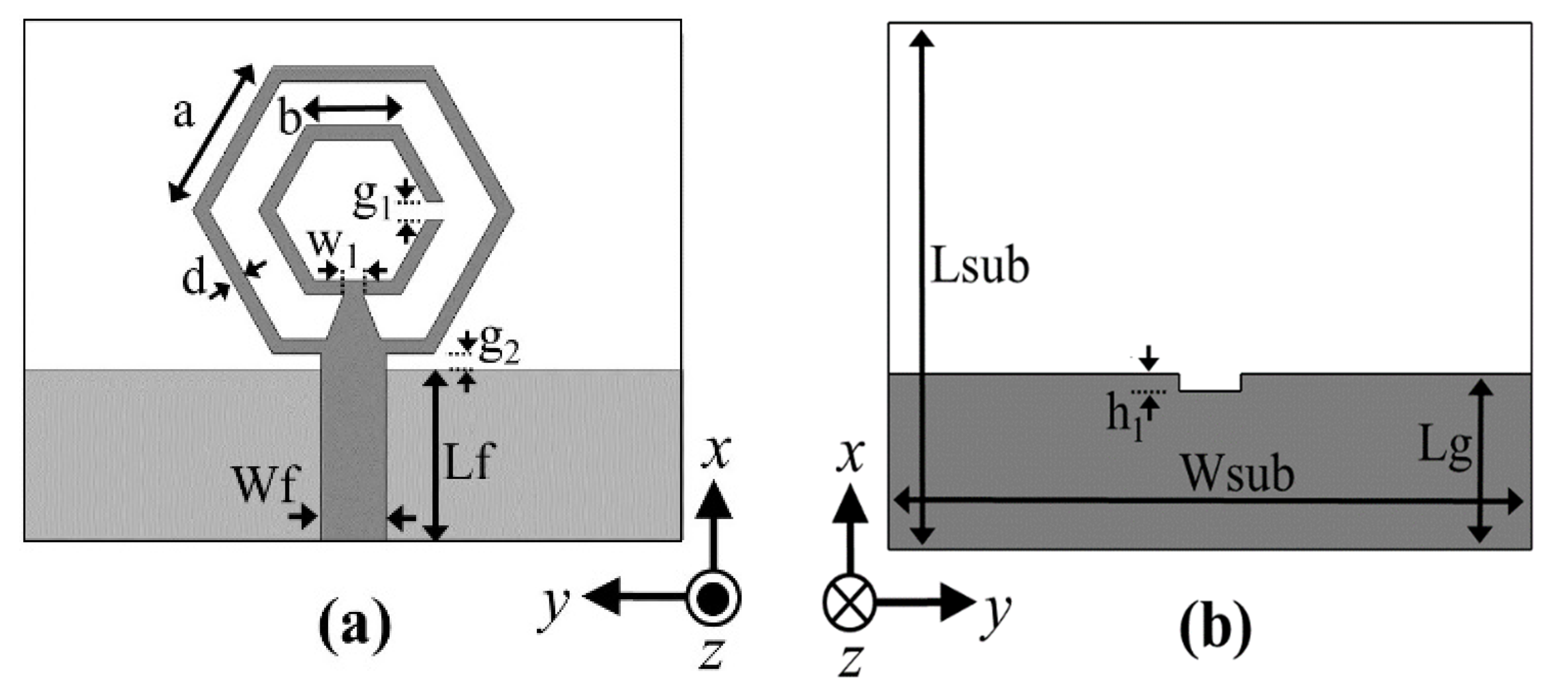
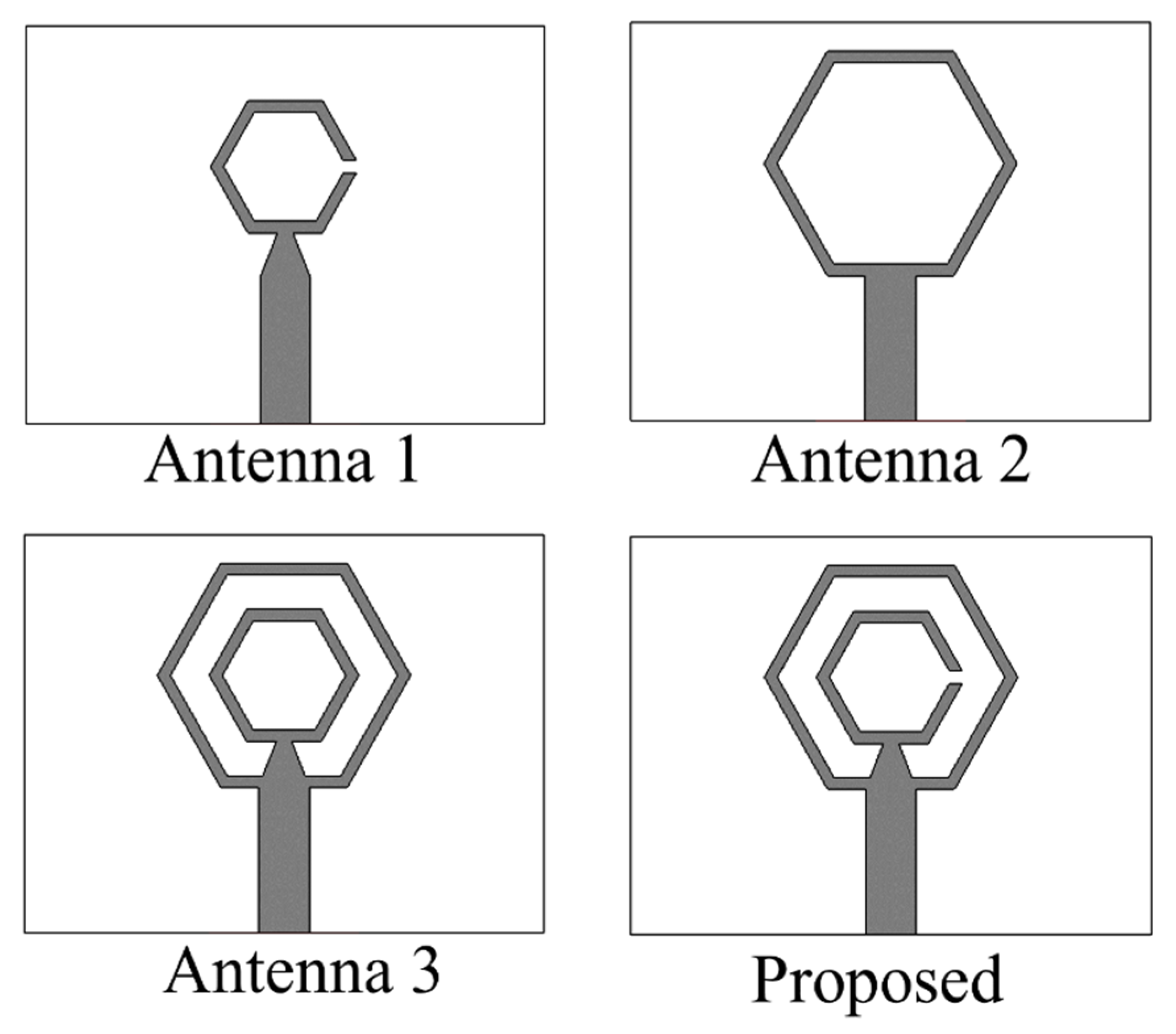
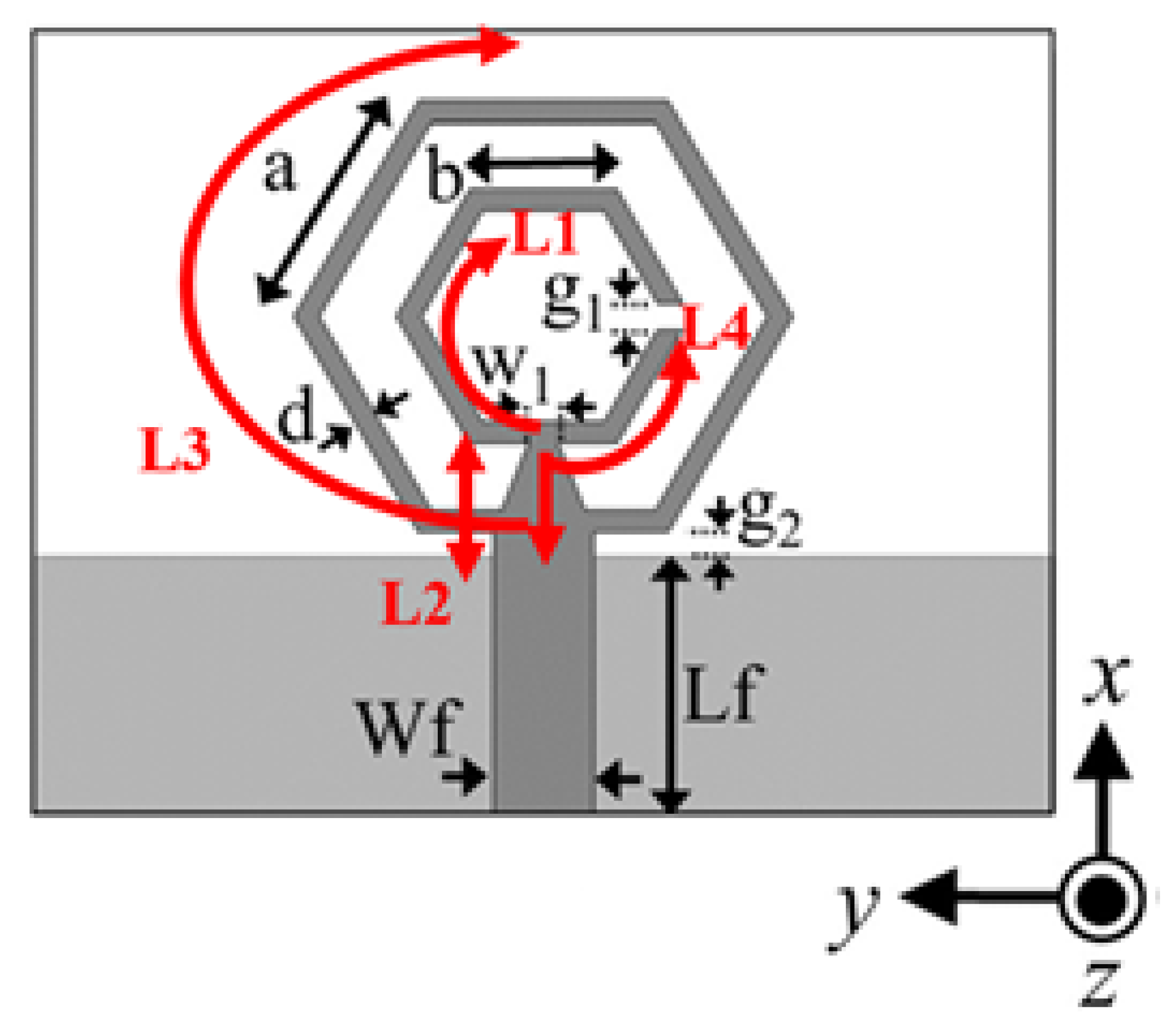
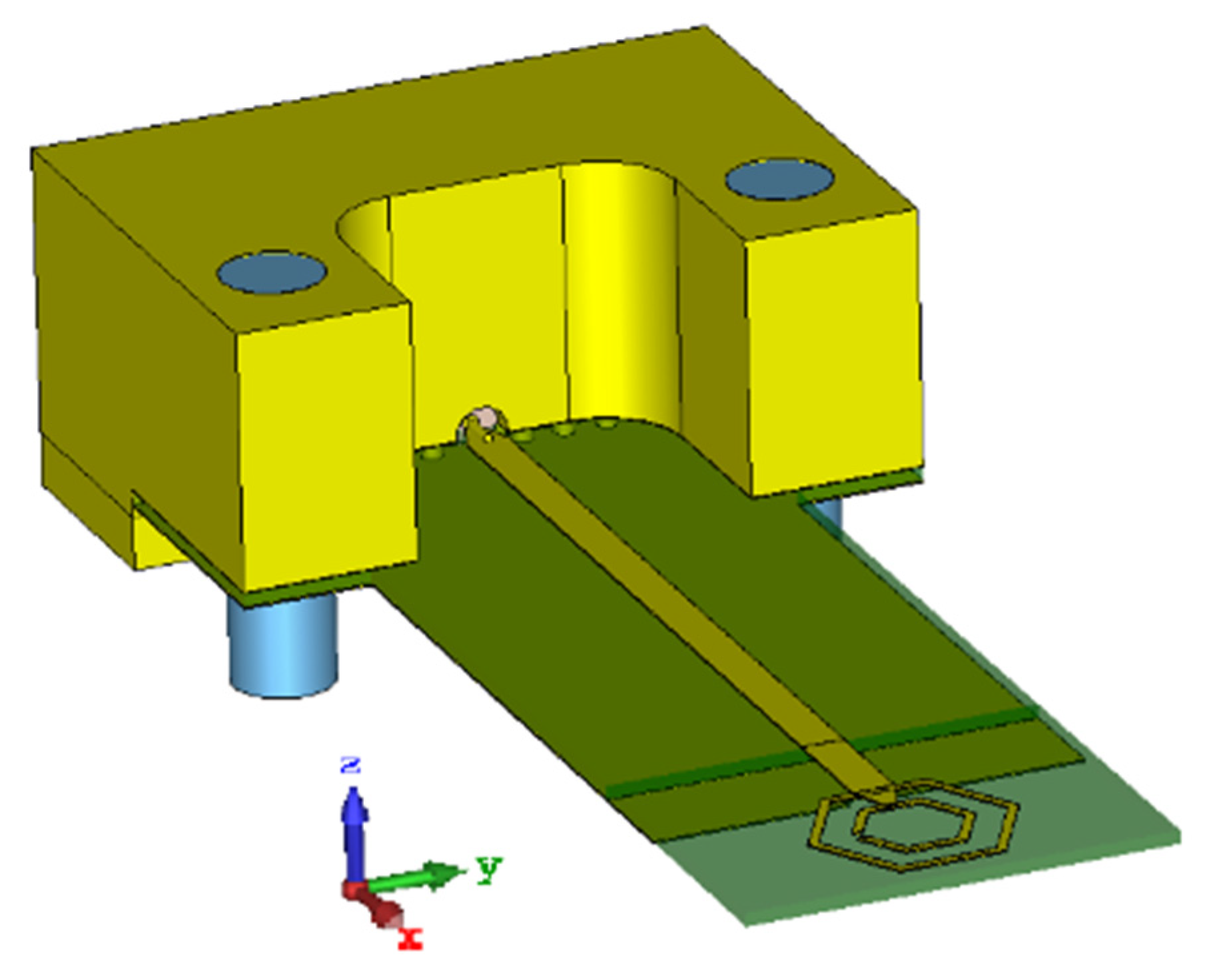
2.1. Physical Configuration

The proposed antenna model is based on the Rogers RT/Duroid 5880 substrate and has a thickness equal to 0.254 mm, a dielectric constant εr = 2.2 and loss tangent tanδ = 0.0009. The antenna length is Lsub = 6 mm and width is Wsub = 8 mm, as shown in Figure 1. The optimized dimensions are listed in Table 1.
The proposed antenna’s front side as shown in Figure 1a has two hexagonal structures; i.e., inner and outer rings. The outer hexagon is a closed ring while the inner hexagon is a split ring with a gap ‘g1’. The ground plane is truncated to the length ‘Lg’ as shown in Figure 1b. The ground plane has a rectangular notch at its center of length ‘h1′ and width ‘Wf’. The radii of the inner and outer hexagonal rings are 0.95 mm and 1.75 mm, respectively. Since the radius of any hexagon is numerically equal to the length of its sides, Figure 1 and Table 1 show the lengths of the hexagons’ sides.

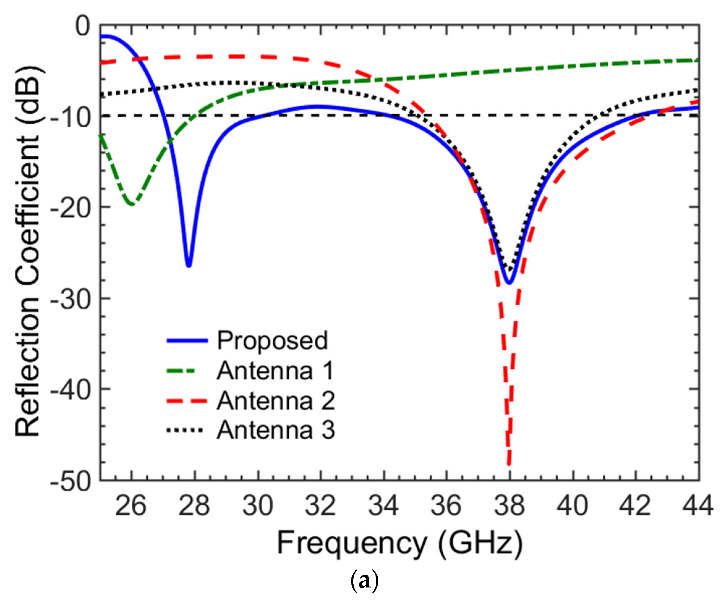
2.2. Design Methodology

The philosophy behind using two rings is to obtain dual-band operation in the millimeter-wave spectrum. This was achieved through a metamaterial-based structure consisting of a closed-ring resonator (CRR) and a split-ring resonator (SRR). Thus, the antenna was expected to operate in two resonant modes. To verify this dual-mode operation, Figure 2 shows the different antenna structures used and Figure 3 shows their corresponding reflection coefficients. The first antenna, which consists of a hexagonal SRR (Antenna 1 shown in Figure 2), has a resonance frequency of 26 GHz and covers the frequency spectrum of interest, as shown in Figure 3. The second antenna is a CRR with a larger hexagon size (Antenna 2 shown in Figure 2) that covers the higher-frequency spectrum with a resonance at 38 GHz, as shown in Figure 3.
These two geometries (Antenna 1 and Antenna 2) are combined to reach at the final Proposed antenna in Figure 2. The reflection coefficient given in Figure 3 shows that the final Proposed antenna has a dual-band coverage at 28 GHz and 38 GHz, respectively. To show the importance of the split used in the inner hexagon structure of Antenna 1, we simulated Antenna 3, which has no split in its inner hexagonal ring, as shown in Figure 2. The reflection coefficient of Antenna 3 shown in Figure 3a indicates that it does not cover the lower required band in the region around 28 GHz. Hence, the split in our proposed antenna plays a key role in producing a band at 28 GHz. Furthermore, it should be noted that the resonance for Antenna 1 shifts from 26 GHz to 28 GHz when an outer ring is introduced in the final Proposed antenna. This shift is caused by the parasitic effect on the inner ring due to its close proximity to the outer ring.
In Figure 3a, it is evident that each of the hexagonal rings is individually responsible for producing a single band; therefore, if their dimensions are varied, the resonance frequency of each band can be effectively controlled. To verify this, first we chose to vary the dimension of the larger ring (CRR) by changing its parameter ‘a’, as shown in Figure 3b. It was clearly seen that as expected, the higher resonant frequency is changed accordingly. Thus, parameter ‘a’ is chosen such that we get a resonance at 38 GHz; its optimum value here is 1.75 mm.
To control the lower-frequency band, there were two options: the first is to change parameter ‘b’, and the second is to change the dimensions of the taper line.
Since the taper line is part of the inner ring, we expect that it also affect the lower-frequency band. The effect of parameter ‘w1′ is shown in Figure 3c. It can be clearly seen that the lower-frequency band is fully adjustable by varying ‘w1′. The optimum value of 0.2 mm has been chosen to obtain a resonance at 28 GHz. Adjusting parameter ‘b’ of the inner hexagon (SRR) has a similar effect and therefore not shown here for brevity.

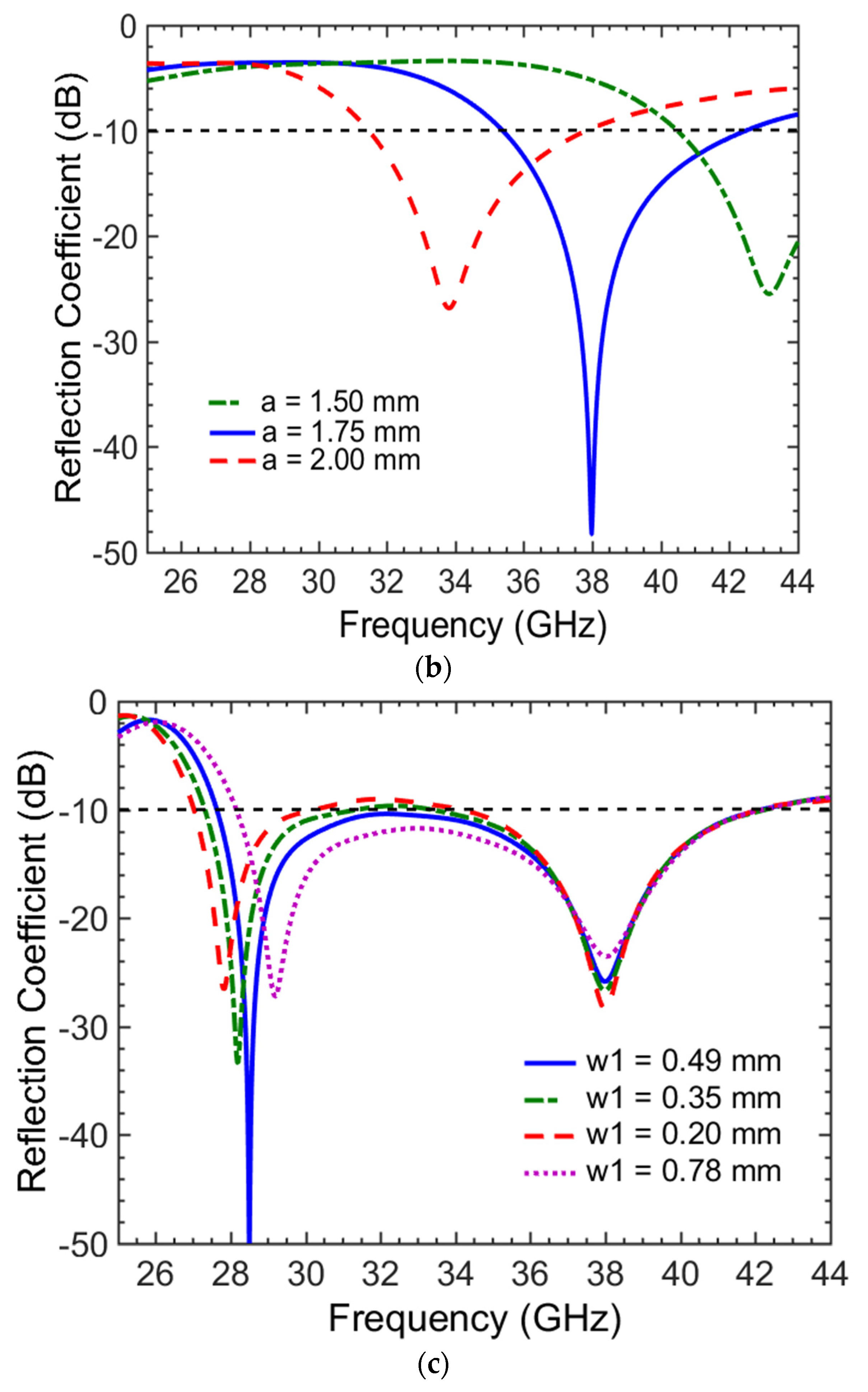
2.3. The Effective Length

The effective electrical length required to resonate a monopole antenna should be around λ/4 or integer multiples of λ/4 for higher modes. For a substrate with an electrical permittivity εr = 2.2, the wavelength at 28 GHz is 7.22 mm and at 38 GHz is 5.32 mm.
As shown in Figure 4a, the total perimeter of the left arm of the inner ring starting from the center of base arm up to the split is 4.175 mm. This has been calculated as L1 = (b/2) + (4×b) − (g1/2) = 4.175 mm, while L2 = 0.88 and d/2 = 0.1 mm. The total physical length of the left arm of the inner ring = L1 + L2 + d/2 = 5.155 mm. The effective radiating length including L2 as ground plane is removed from this part of the feed line, hence the total electrical length of the left arm of inner ring at 28 GHz becomes 0.72λ or approximately (3/4)λ. Now, coming towards the right-side arm of the inner ring, the total physical length (i.e., L4) of this small arm of the inner hexagon is: L4 = b/2 + b + L2 + d/2 − (g1/2) = 2.3 mm. This L4 is 0.32λ at 28 GHz and 0.44λ at 38 GHz for our chosen substrate. Therefore, this part of the inner hexagon contributes more to the 28 GHz resonant frequency.
Now, considering the outer hexagonal ring, which is actually responsible for generating the resonance response at 38 GHz, the outer ring is symmetrical across its x-axis and hence we take half of its total perimeter; i.e., starting from the center of the base arm up to the center of the upper arm. The extra length above the ground also will also be added; this is calculated as follows: L3 = {(6 × a)/2} + (Lf−Lg) + (d/2). This length turns out to be 10.8 mm, which is 2.03λ at 38 GHz. Thus, we can say that the outer hexagon resonates in a higher-order mode with an electrical length of approximately 2λ.

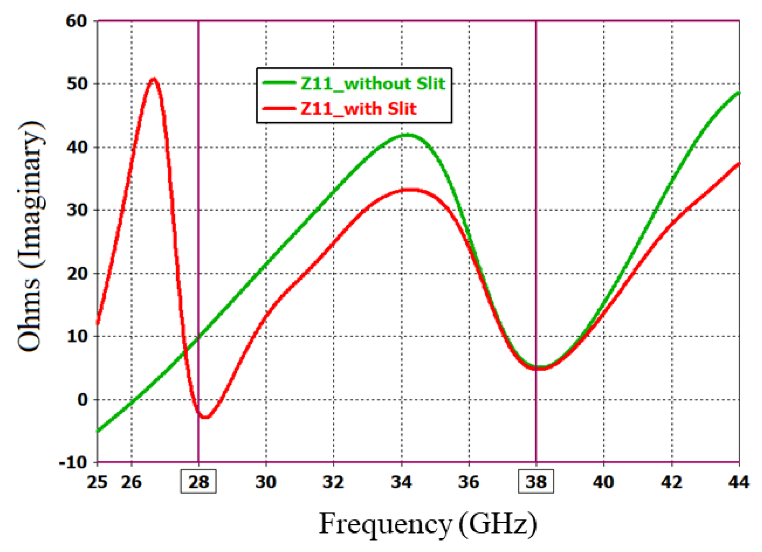
2.4. The Capacitive Effect of the Split (g)

To see whether the split change the effective impedance of the antenna, we compare the imaginary part of the input impedance for the two cases; i.e., Antenna 3 and the Proposed antenna shown in Figure 2. The imaginary part of the input impedance for both of the cases is depicted in Figure 5 below. It can be seen that reactance of the antenna is inductive for no-split case (Antenna 3) at 28 GHz. However, it transforms into capacitive reactance when the split is introduced (i.e., the Proposed antenna), generating a strong resonance at 28 GHz.

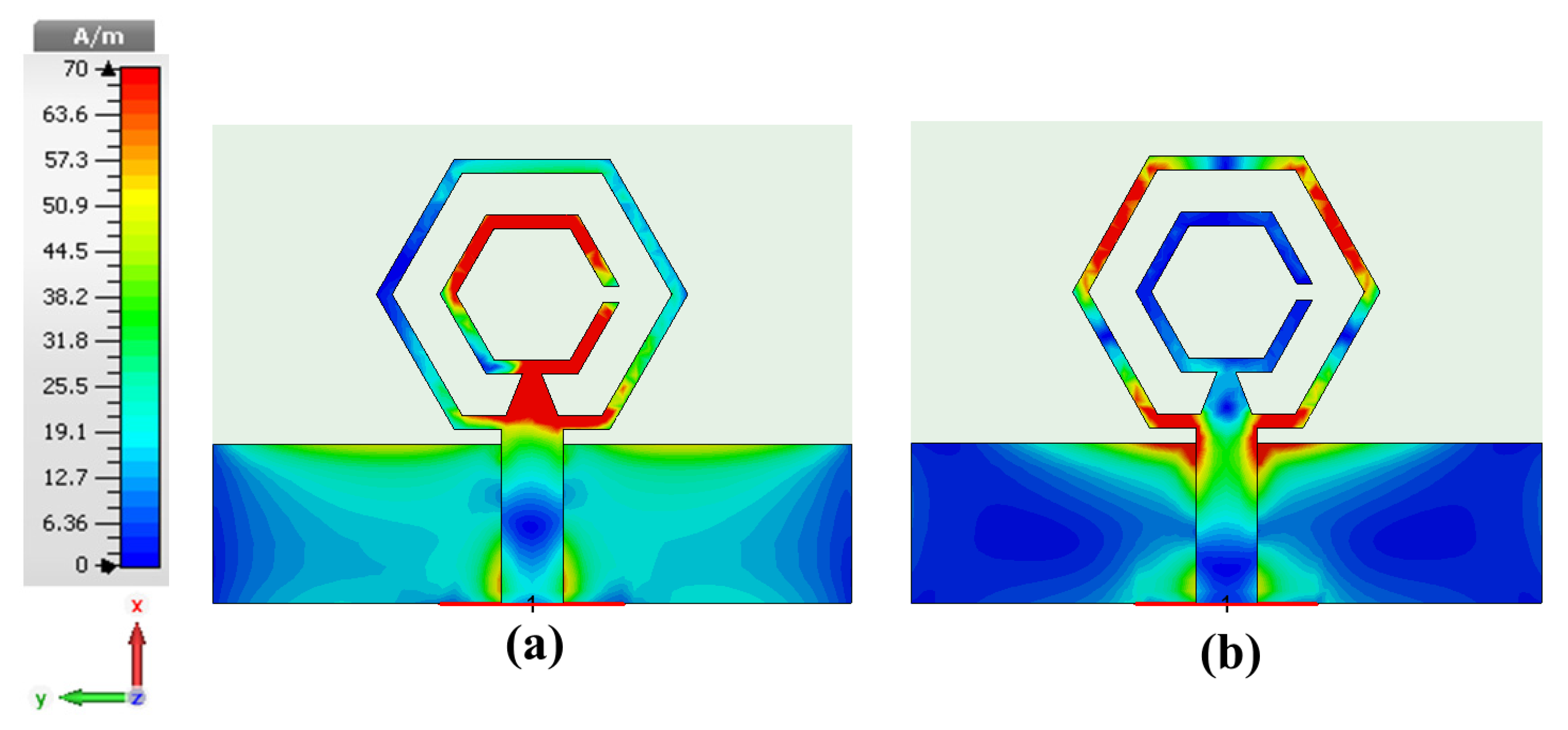
2.5. Surface Current Distribution

To further investigate the role of the hexagonal rings in the generation of the two resonant modes, the surface current distribution shown in Figure 6 is analyzed. At 28 GHz, it can be easily seen that the inner SRR exhibits highest current distribution, as shown in Figure 6a. Similarly, at 38 GHz, it is observed that the outer CRR has the highest current distribution as shown in Figure 6b. Hence, it is verified that the SRR and CRR indeed give rise to the 28 GHz and 38 GHz resonant modes respectively, as predicted.
These hexagonal rings provide a potential benefit of creating a dual-beam radiation pattern. Dual-beam antennas are useful for providing spatial diversity in radio communications [23] and also play a vital role in cases where interference between adjacent channels requires minimization [24]. A dual-beam antenna such as that in [9] provides a dual-beam radiation pattern at the cost of increased complexity and bulkiness. The design in [9] employed multiple arrays of metamaterial inclusions to generate two beams that were ±60° apart. In this paper, we used the inherent symmetric nature of a hexagon to conceive a dual-beam radiation pattern. To grasp the idea, consider the current distribution shown in Figure 6b for 38 GHz. The current is symmetrically distributed (shown in red color) along the two sides of the outer hexagon. This current distribution results in two distinct radiation beams angled at ±45° with reference to the x-axis.
As depicted in Figure 7, the two beams are created by the angled arms of the hexagonal structure. It should be noted that any two opposite arms are at an angle of 60° to each other. When the current distribution (see Figure 6) is maximum in these arms, two beams ideally at 120° apart should be generated; however, in this case the two beams were at ±45° (i.e., 90° apart). This is because of the current distribution on the other arms as well. The ideal and actual beam formations are shown in Figure 7 with blue and red colors, respectively. The hexagonal geometry with optimized dimensions and a very judicious placement of the tapered feedline provides a current distribution at the hexagonal arms that allows it to create these two distinct beams. Similarly, when considering the current distribution shown in Figure 6a for 28 GHz, it can be seen that the current is almost symmetrical in the inner two side arms of the inner hexagon. In this case, we see some additional surface current distribution on the top and bottom right side of the inner hexagon; therefore, we obtain a dual beam towards the front side with some minor lobes towards the back side of the antenna.

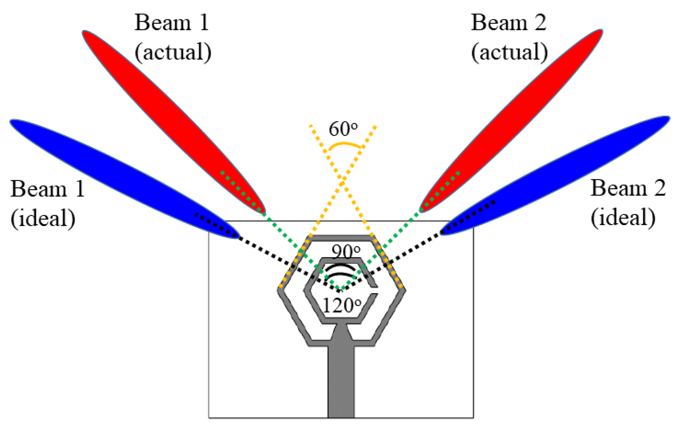
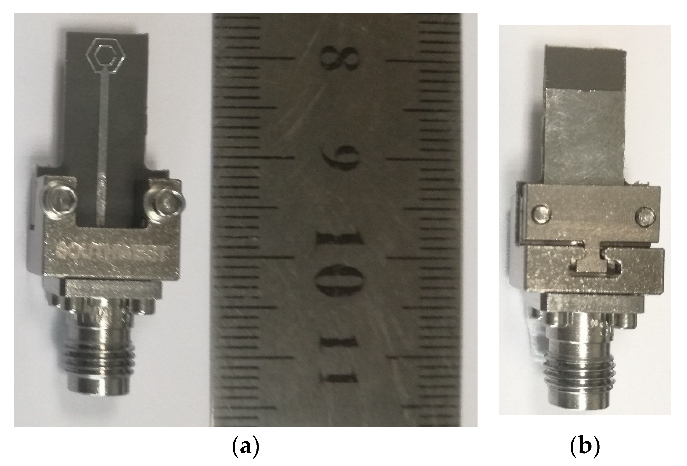
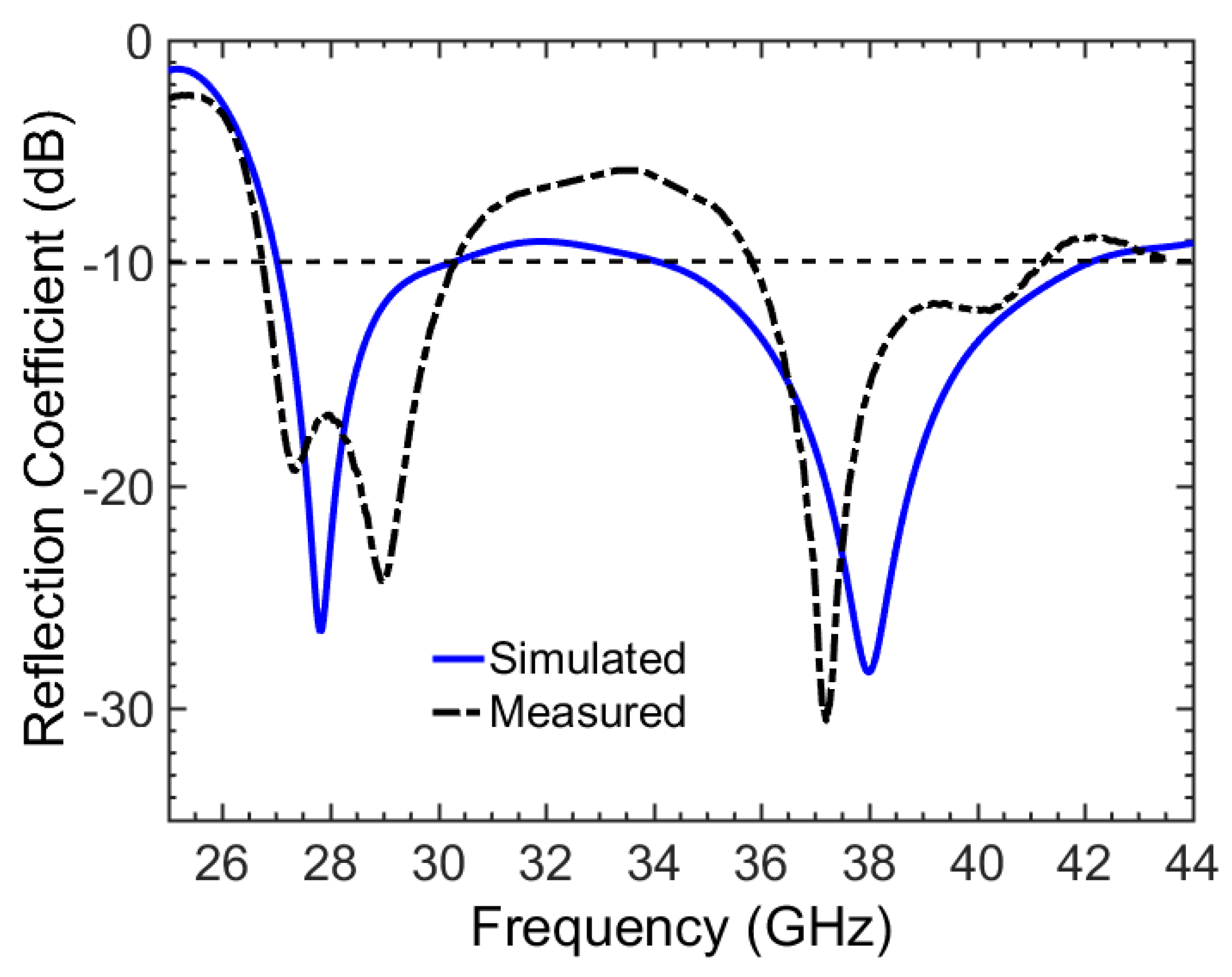
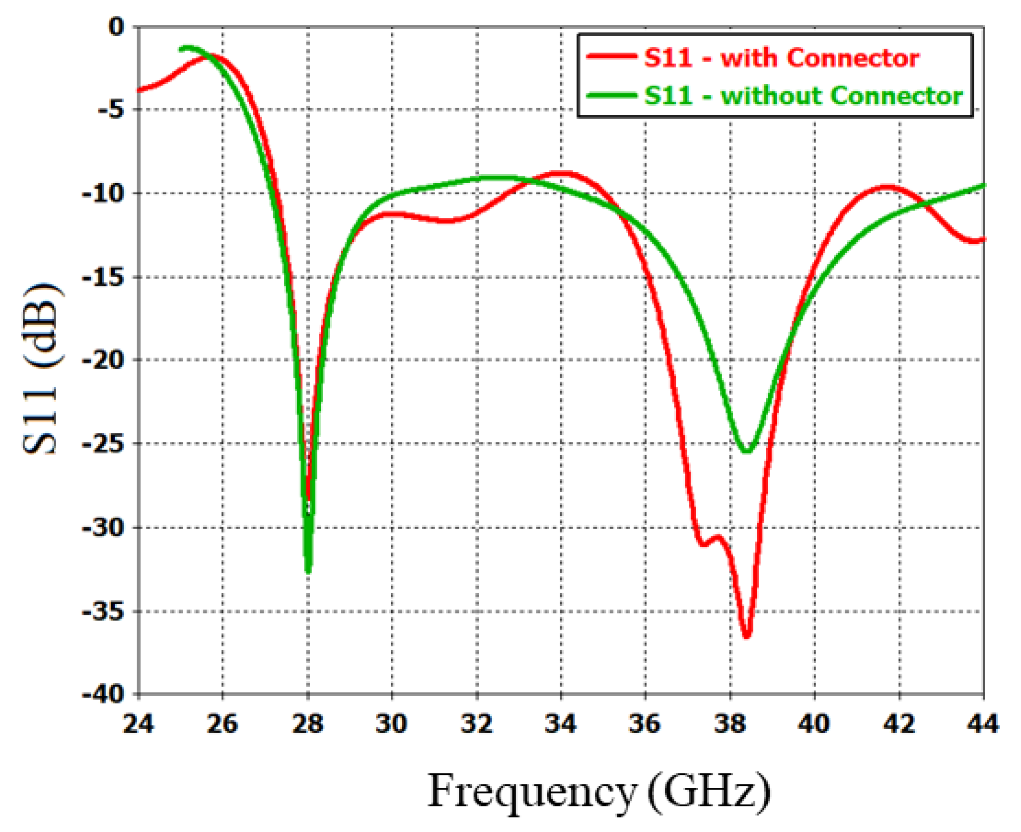
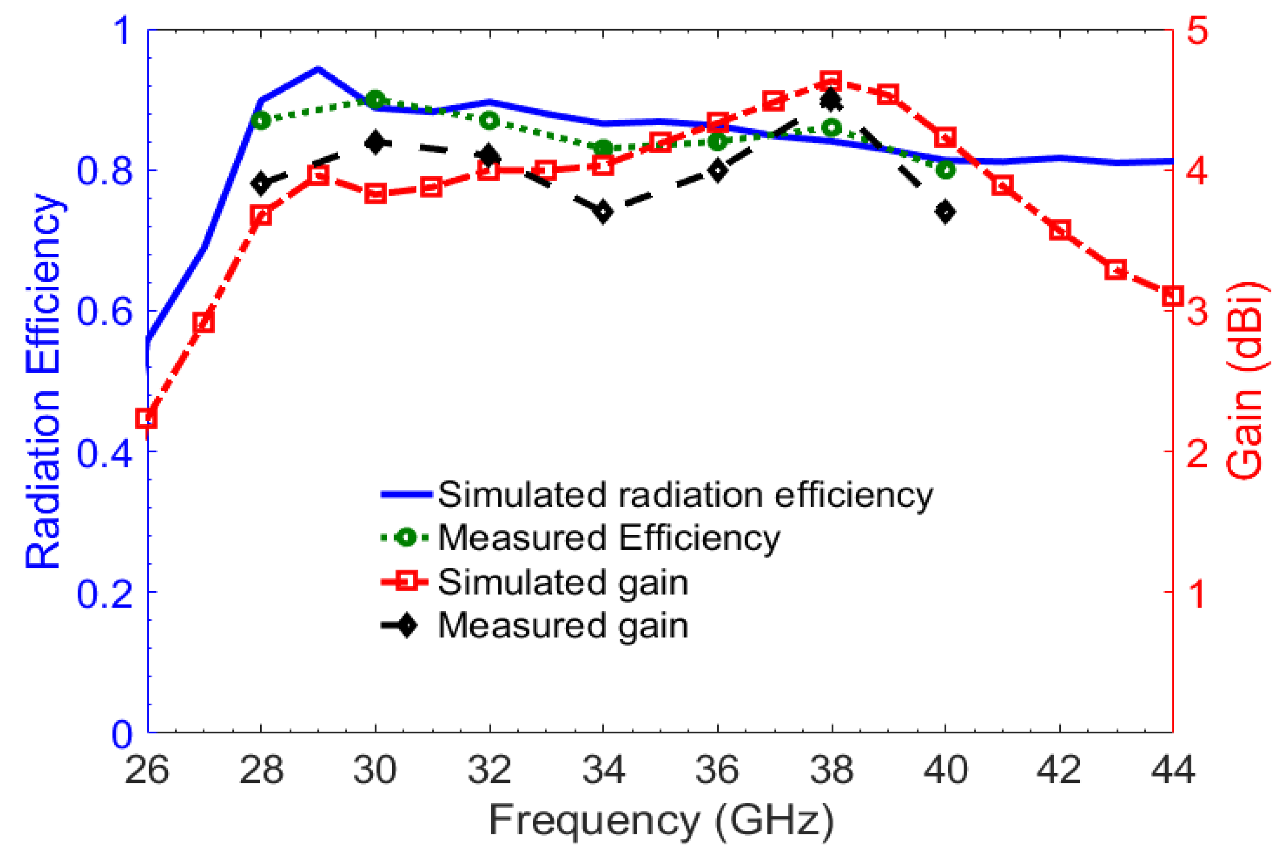
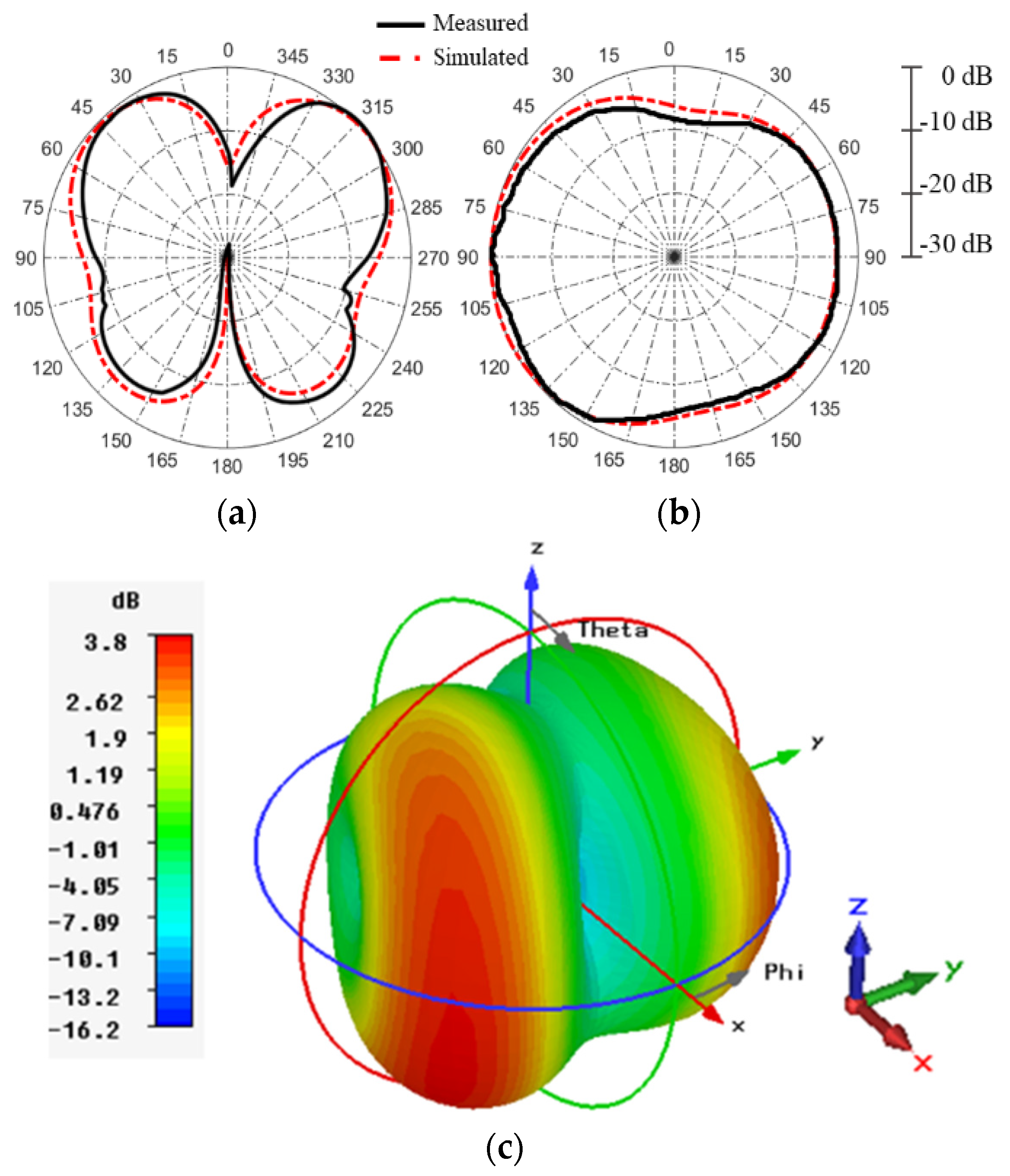
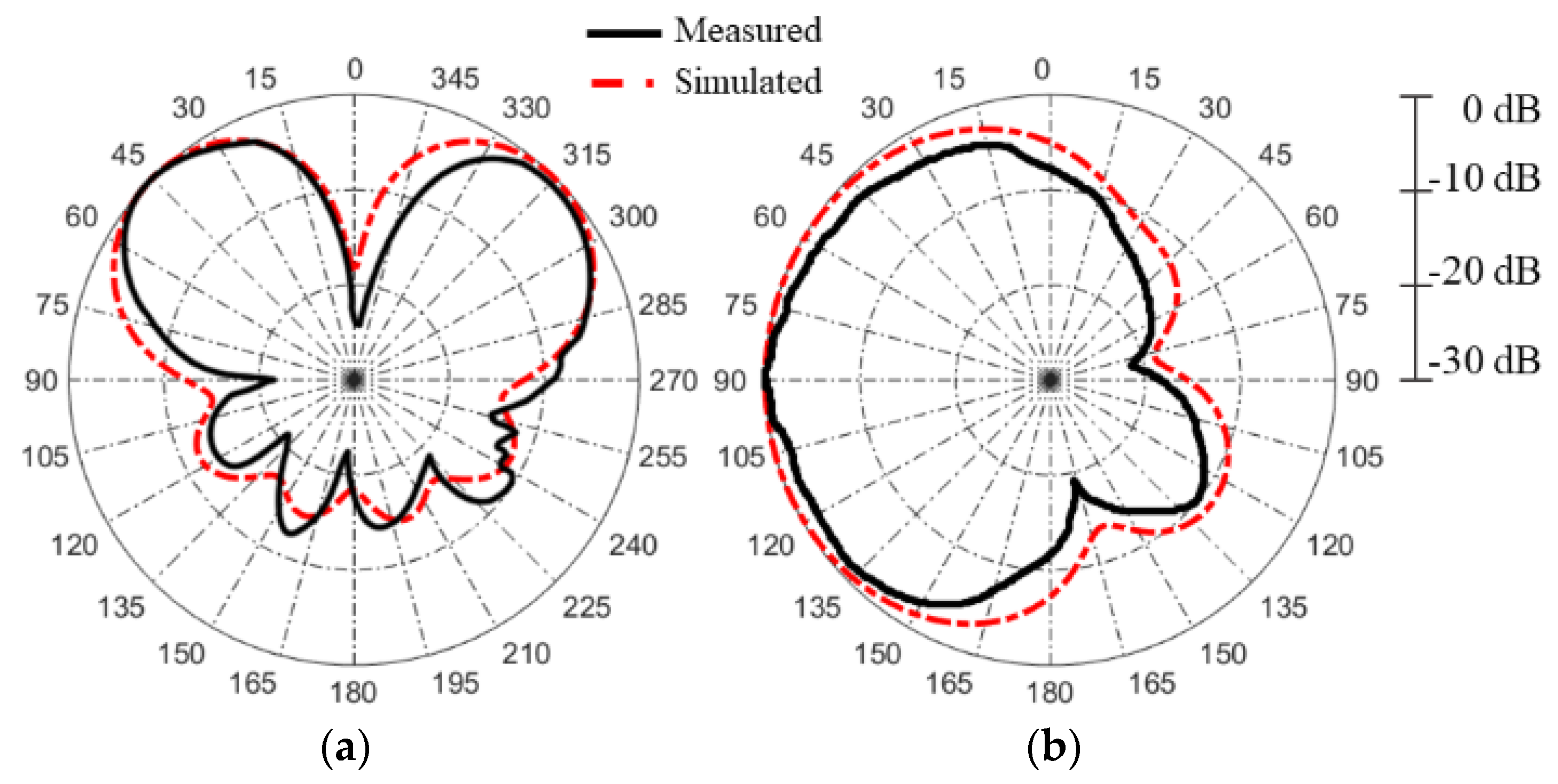
3. Measurement Results

The antenna was fabricated on Rogers 5880 board using an in-house standard PCB manufacturing facility (LPKF S103). The fabricated prototype was then fixed with a Southwest RF connector as shown in Figure 8.
The feed line was extended for easy mounting of the antenna onto the connector. The antenna was tested for radiation patterns in our in-house anechoic chamber facility (range: 800 MHz–40 GHz). The simulated and measured reflection coefficients (S11) are shown in Figure 9. The simulated S11 showed that the lower band ranged from 26.983 GHz to 29.814 GHz and the upper band from 34.29 GHz to 42.206 GHz. The measured S11 followed the same trend and showed two distinct bands; i.e., at 26.75–30.31 GHz and 35.83–41.22 GHz. Thus, the desired bands of 28 GHz and 38 GHz were well covered with total bandwidths of 3.56 GHz (12.71%) and 5.39 GHz (14.18%), respectively.
The antenna was also simulated using an approximate model of an actual Southwest microwave connector and extended feed line. The simulation model and reflection coefficients are shown in Figure 10. It can be observed that there are two extra resonances within each band in our measured results. Therefore, it can be said that these extra resonances were not due to the calibration problem, but in fact due to the introduction of the connector for measurement purposes. In an actual 5G applications in which such antennas will be used in mobile handsets, this type of large connectors are not employed; therefore, this connector effect is not very critical for practical applications.
The in-band radiation efficiency of the antenna remains above 80%. Both the radiation efficiency and gain plots are shown in Figure 11. The measured gain and radiation efficiency of the antenna agree well with those simulated. At 28 GHz, the antenna has a measured gain equal to 3.9 dBi; at 38 GHz, the absolute gain was 4.5 dBi. The radiation patterns of the proposed antenna at 28 and 38 GHz are depicted in Figure 12 and Figure 13, respectively.
The patterns in the θ = 90° planes (xy-planes) indicate a dual beam operation of the antenna. There are two maxima at ϕ = 45° and ϕ = 315° for both the 28 GHz and 38 GHz bands, as shown in Figure 12a,b and Figure 13a,b, respectively. The ϕ = 45° planes are shown in Figure 12b and Figure 13b, whereas the ϕ = 315° is not shown here for brevity. It can be seen in the radiation patterns that the dual beams are separated by approximately 90°. As already discussed above, dual-beam radiation patterns are desirable in applications where space diversity is required. To provide an illustration of the directivity of the antenna, the overall 3D radiation pattern is shown in Figure 12c for 28 GHz and in Figure 13c for 38 GHz. The radiation pattern analysis shows that the antenna has a very directive dual-beam pattern that are suitable for dual-beam operation at higher frequencies.

4. Conclusions

A dual-band planar antenna with hexagonal-shaped SRR and CRR structures for millimeter-wave communication systems was presented. The dimensions of both rings were optimized so that they covered the two important 5G frequency bands of 28 GHz and 38 GHz. The antenna had a large bandwidth of 3.56 and 5.39 GHz at 28 GHz and 38 GHz, respectively. The unique structural layout of the antenna enabled fine selection of resonance points at the desired frequency in the millimeter-wave spectrum. The antenna had a simulated radiation efficiency of more than 80% and its measured gain was as high as 4.5 dBi. The antenna’s low fabrication cost, large bandwidth, high gain, and dual-band operation suggested that this antenna will be quite useful in future mobile phones systems working in the millimeter-wave communication bands.

Author Contributions

H.U. designed and performed the simulations of the antenna. He also performed measurements and wrote the manuscript. H.F.A. contributed to the concept and revised the entire manuscript. A.R. contributed to the writeup and revised the manuscript. F.A.T. conceived the idea, analyzed the results, interpreted the data, and supervised the whole work. All authors have read and agreed to the published version of the manuscript.

Funding

This research was funded by the Higher Education Commission (HEC) of Pakistan through its National Research Program for Universities (NRPU) under Project No. 10070/Federal/NRPU.

Data Availability Statement

Not applicable.

Conflicts of Interest

The authors declare no competing interests.

References

  1. International Telecommunication Union-Radiocom Sector (ITU-R), Final Acts-World Radiocommunication Conference (WRC-15). Available online: http://handle.itu.int/11.1002/pub/80d4e1c0-en (accessed on 1 June 2020).
  2. Roh, W.; Seol, J.-Y.; Park, J.; Lee, B.; Lee, J.; Kim, Y.; Cho, J.; Cheun, K.; Aryanfar, F. Millimeter-wave beamforming as an enabling technology for 5G cellular communications: Theoretical feasibility and prototype results. IEEE Commun. Mag. 2014, 52, 106–113. [Google Scholar] [CrossRef]
  3. Federal Communications Commission (FCC), Report and Order And (ECC) Further Notice of Proposed Rulemaking in the Matter of Use of Spectrum Bands above 24 GHz for Mobile Radio Services (GN Docket No. 14-177), Doc. FCC-16-89, 14 July 2016. Available online: https://docs.fcc.gov/public/attachments/FCC-16-89A1.pdf (accessed on 7 June 2019).
  4. 5G Americas White Paper on 5G Spectrum Recommendations, April 2017. Available online: www.5gamericas.org (accessed on 7 August 2020).
  5. Park, S.-J.; Shin, D.-H. Low Side-Lobe Substrate-Integrated-Waveguide Antenna Array Using Broadband Unequal Feeding Network for Millimeter-Wave Handset Device. IEEE Trans. Antennas Propag. 2015, 64, 923–932. [Google Scholar] [CrossRef]
  6. Choubey, P.N.; Hong, W.; Hao, Z.C.; Chen, P.; Duong, T.V.; Mei, J. A Wideband Dual-Mode SIW Cavity-Backed Triangular-Complimentary-Split-Ring-Slot (TCSRS) Antenna. IEEE Trans. Antennas Propag. 2016, 64, 2541–2545. [Google Scholar] [CrossRef]
  7. Khalily, M.; Tafazolli, R.; Rahman, T.A.; Kamarudin, M.R. Design of Phased Arrays of Series-Fed Patch Antennas With Reduced Number of the Controllers for 28-GHz mm-Wave Applications. IEEE Antennas Wirel. Propag. Lett. 2015, 15, 1305–1308. [Google Scholar] [CrossRef]
  8. Bisharat, D.J.; Liao, S.; Xue, Q. High Gain and Low Cost Differentially Fed Circularly Polarized Planar Aperture Antenna for Broadband Millimeter-Wave Applications. IEEE Trans. Antennas Propag. 2015, 64, 33–42. [Google Scholar] [CrossRef]
  9. Dadgarpour, A.; Zarghooni, B.; Virdee, B.S.; Denidni, T.A. Single End-Fire Antenna for Dual-Beam and Broad Beamwidth Operation at 60 GHz by Artificially Modifying the Permittivity of the Antenna Substrate. IEEE Trans. Antennas Propag. 2016, 64, 4068–4073. [Google Scholar] [CrossRef] [Green Version]
  10. Dadgarpour, A.; Sorkherizi, M.S.; Kishk, A. Wideband Low-Loss Magnetoelectric Dipole Antenna for 5G Wireless Network With Gain Enhancement Using Meta Lens and Gap Waveguide Technology Feeding. IEEE Trans. Antennas Propag. 2016, 64, 5094–5101. [Google Scholar] [CrossRef]
  11. Ta, S.X.; Choo, H.; Park, I. Broadband Printed-Dipole Antenna and Its Arrays for 5G Applications. IEEE Antennas Wirel. Propag. Lett. 2017, 16, 2183–2186. [Google Scholar] [CrossRef]
  12. Chu, Q.X.; Li, X.R.; Ye, M. High-Gain Printed Log-Periodic Dipole Array Antenna With Parasitic Cell for 5G Communication. IEEE Trans. Antennas Propag. 2017, 65, 6338–6344. [Google Scholar] [CrossRef]
  13. Zhu, Q.; Ng, K.B.; Chan, C.H.; Luk, K.-M. Substrate-Integrated-Waveguide-Fed Array Antenna Covering 57–71 GHz Band for 5G Applications. IEEE Trans. Antennas Propag. 2017, 65, 6298–6306. [Google Scholar] [CrossRef]
  14. Lee, S.; Kim, S.; Choi, J. Dual-Band Dual-Polarized Proximity Fed Patch Antenna for 28 GHz/39 GHz 5G Millimeter-Wave Communications. In Proceedings of the 2019 13th European Conference on Antennas and Propagation (EuCAP), Krakow, Poland, 31 March–5 April 2019; pp. 1–5. [Google Scholar]
  15. Hong, T.; Zhao, Z.; Jiang, W.; Xia, S.; Liu, Y.; Gong, S. Dual-Band SIW Cavity-Backed Slot Array Using TM020 and TM120 Modes for 5G Applications. IEEE Trans. Antennas Propag. 2019, 67, 3490–3495. [Google Scholar] [CrossRef]
  16. Deckmyn, T.; Cauwe, M.; Ginste, D.V.; Rogier, H.; Agneessens, S. Dual-Band (28,38) GHz Coupled Quarter-Mode Substrate-Integrated Waveguide Antenna Array for Next-Generation Wireless Systems. IEEE Trans. Antennas Propag. 2019, 67, 2405–2412. [Google Scholar] [CrossRef] [Green Version]
  17. Ullah, H.; Tahir, F.A. Broadband planar antenna array for future 5G communication standards. IET Microwaves, Antennas Propag. 2019, 13, 2661–2668. [Google Scholar] [CrossRef]
  18. Ullah, H.; Tahir, F.A. A broadband wire hexagon antenna array for future 5G communications in 28 GHz band. Microw. Opt. Technol. Lett. 2018, 61, 696–701. [Google Scholar] [CrossRef]
  19. Ullah, H.; Tahir, F.A. A wide-band rhombus monopole antenna array for millimeter wave applications. Microw. Opt. Technol. Lett. 2020, 62, 2111–2117. [Google Scholar] [CrossRef]
  20. Ullah, H.; Tahir, F.A. A Novel Snowflake Fractal Antenna for Dual-Beam Applications in 28 GHz Band. IEEE Access 2020, 8, 19873–19879. [Google Scholar] [CrossRef]
  21. Ullah, H.; Tahir, F.A. A High Gain and Wideband Narrow-Beam Antenna for 5G Millimeter-Wave Applications. IEEE Access 2020, 8, 29430–29434. [Google Scholar] [CrossRef]
  22. Ullah, H.; Tahir, F.A.; Ahmad, Z. A Dual-band Hexagon Monopole Antenna for 28 and 38 GHz Millimeter-Wave Communications. In Proceedings of the 2018 IEEE International Symposium on Antennas and Propagation & USNC/URSI National Radio Science Meeting, Boston, MA, USA, 8–13 July 2018; pp. 1215–1216. [Google Scholar]
  23. Kirthiga, S.; Jayakumar, M. Performance of Dualbeam MIMO for Millimeter Wave Indoor Communication Systems. Wirel. Pers. Commun. 2014, 77, 289–307. [Google Scholar] [CrossRef]
  24. Hosoya, K.; Prasad, N.; Ramachandran, K.; Orihashi, N.; Kishimoto, S.; Rangarajan, S.; Maruhashi, K. Multiple Sector ID Capture (MIDC): A Novel Beamforming Technique for 60-GHz Band Multi-Gbps WLAN/PAN Systems. IEEE Trans. Antennas Propag. 2015, 63, 81–96. [Google Scholar] [CrossRef]
Figure 1. Geometry of the proposed antenna: (a) front side; (b) back side.
Electronics 11 03256 g001
Figure 2. Front sides of the geometries of Antennas 1, 2, and 3 and the final Proposed antenna.
Electronics 11 03256 g002
Figure 3. (a) Reflection coefficients of Antennas 1, 2, and 3 and the final Proposed antenna; (b) effect of outer hexagonal ring size on reflection coefficient; (c) effect of taper line width on the first resonant frequency.
Electronics 11 03256 g003aElectronics 11 03256 g003b
Figure 4. Electrical lengths of the two rings.
Electronics 11 03256 g004
Figure 5. Effect of inner ring split on antenna reactance.
Electronics 11 03256 g005
Figure 6. Surface current distribution: (a) 28 GHz; (b) 38 GHz.
Electronics 11 03256 g006
Figure 7. Depiction of the dual-beam phenomenon.
Electronics 11 03256 g007
Figure 8. Fabricated antenna: (a) front side; (b) back side.
Electronics 11 03256 g008
Figure 9. Simulated and measured reflection coefficient (S11) magnitudes.
Electronics 11 03256 g009
Figure 10. Simulated reflection coefficients (S11) with connector model.
Electronics 11 03256 g010aElectronics 11 03256 g010b
Figure 11. Simulated and measured radiation efficiency gains.
Electronics 11 03256 g011
Figure 12. Radiation patterns at 28 GHz for (a) θ = 90° and (b) ϕ = 45° planes. (c) The 3D radiation pattern at 28 GHz.
Electronics 11 03256 g012
Figure 13. Radiation patterns at 38 GHz for (a) θ = 90° and (b) ϕ = 45° planes. (c) The 3D radiation pattern at 38 GHz.
Electronics 11 03256 g013aElectronics 11 03256 g013b
Table 1. Optimized parameters of the antenna.
ParameterValue (mm)ParameterValue (mm)
a1.75Lsub6
b0.95Wsub8
d0.2Lg2
g10.2Wf0.78
w10.2Lf2
h10.2g20.2
Publisher’s Note: MDPI stays neutral with regard to jurisdictional claims in published maps and institutional affiliations.

