Communication

A Five-Level RF-PWM Method with Third and Fifth Harmonic Elimination for All-Digital Transmitters

1
The Sixty-Third Research Institute, National University of Defense Technology, Nanjing 210007, China
2
School of Electronic and Information Engineering, Nanjing University of Information Science and Technology, Nanjing 210044, China
*
Author to whom correspondence should be addressed.
Electronics 2022, 11(19), 3257; https://doi.org/10.3390/electronics11193257
Submission received: 25 August 2022 / Revised: 4 October 2022 / Accepted: 5 October 2022 / Published: 10 October 2022
(This article belongs to the Special Issue Signal Processing in Wireless Communications)

Abstract

:
An appropriate pulse-coding algorithm is the key to achieving an efficient switched-mode power amplification in all-digital transmitters. A five-level RF-PWM method with third and fifth harmonic elimination is proposed to relax the requirements of the filter and to reduce the control complexity of the SMPA for all-digital transmitters. By controlling the pulse width and the center position of three-level sub-pulses, third and fifth harmonic elimination is achieved. Meanwhile, the control complexity of the SMPA is reduced by the decrease in the output-signal-level number. Finally, the feasibility of the method is verified by simulation. For the 16QAM signal with a carrier frequency of 200 MHz, the proposed method can achieve third harmonic suppression of −46.24 dBc and fifth harmonic suppression of −54.05 dBc when coding efficiency reaches 77.51%.

1. Introduction

In recent years, the rapid increase in wireless communication requirements has brought challenges to the traditional analog architecture of transmitters, especially as the current trend is to achieve most of the functions of the digital domain by software-defined radio (SDR) techniques [1]. An all-digital transmitter [2,3,4,5] (ADTx) has flexible reconfigurability and programmability and meets the demand of SDR technology. The development of high-speed switching devices, such as the switched-mode power amplifier (SMPA), also brings the possibility of realization of the ADTx. However, the broadband requirement of SDR is a pressing issue in the implementation of the ADTx.
The ADTx is mainly composed of the directly digital-radio-frequency modulator (DDRFM), the switched-mode power amplifier (SMPA) and the tunable filter [6]. To handle the inherently strong nonlinearity of the SMPA, the DDRFM adopts pulse coding [7] to convert the digital RF signal into a pulse signal. Massive quantization noise in the pulse signal can be suppressed by a suitable pulse-coding method. Therefore, pulse coding [8] becomes crucial to achieving the high linearity and efficiency of the ADTx [9].
RF-PWM [10] is one of the most suitable pulse-coding algorithms for the ADTx. Based on existing implementation architectures of the ADTx, it can be digitally achieved by polar [11], quadrature [12] and outphasing [13] transmitters, and the polar architecture for the ADTx is commonly used for RF-PWM. Under the polar architecture, apart from the novel RF model, a baseband model for RF-PWM is proposed [14]. The ADTx structure based on the proposed RF-PWM method is shown in Figure 1. In this structure, the CORDIC circuit converts the baseband signal to an envelope signal a(t) and a phase signal φ(t). The threshold signal Vthi (t) (I = 1, 2, …, n) is generated by the look-up table related to a(t). The phase modulator generates the reference signal refi (t) (i = 1, 2, …, n) with a different phase. The sub-pulses are generated by the comparators, amplified and synthesized by SMPAs.
However, the implementation of RF-PWM still has challenges. Plenty of high-order harmonics in the RF-PWM output pulse not only place high demands on the tuning filter, but they also require the modulator and SMPA to have the ability to handle wideband signals. In addition, the dynamic range for the RF-PWM signal decreases with the rise of the carrier frequency fc. Thus, it will bring distortions of swallowed pulses when the pulse width of the output signal is extremely narrow [15].
To improve the coding efficiency and dynamic range, the multilevel RF-PWM scheme [16] is proposed to reduce quantization noise and harmonic distortion by increasing the number of quantization levels; however, it still needs a high Q filter to suppress harmonics. Theoretically, the increase in quantization levels improves the coding efficiency and dynamic range and reduces harmonic distortion. However, it will also increase the control complexity of the SMPA. Considering the control complexity of the SMPA and the demand of performance, the five-level scheme is a good compromise [17]. A five-level MPWM method is proposed to improve the bandwidth of the filter [8] without cancelling the harmonics. To eliminate the harmonic components, the selective harmonic-elimination pulse-width modulator (SHE-PWM) [18,19,20] is proposed. The PWM waveform and harmonic components can be expressed by the Fourier series in the SHE-PWM method. Then, a group of nonlinear and transcendental equations is obtained by setting the selected low-order harmonics to zero, and the harmonic elimination is implemented by solving the obtained group of equations. According to this selective harmonic elimination theory, a five-level RF-PWM method with third harmonic elimination is proposed [5]. The method enhances the output filter bandwidth by eliminating the third harmonic, but it has a limited effect on relaxing the output filtering requirements. Therefore, eliminating the third and fifth harmonics simultaneously can significantly improve the output filter bandwidth. The schematic diagram of the harmonics is shown in Figure 2. Passband 1 is the bandwidth of filter 1 in the existing RF-PWM method with third harmonic elimination. Passband 2 is the bandwidth of filter 2 in the proposed method with third and fifth harmonic elimination. As shown in Figure 2, the bandwidth of the filter in the proposed method is improved. The harmonics of an odd number from the fundamental component to the 13th harmonic is shown in Figure 2 and the 3rd, 5th and 9th harmonics are eliminated.

2. The Third and Fifth Harmonic Elimination Method for Five-Level RF-PWM

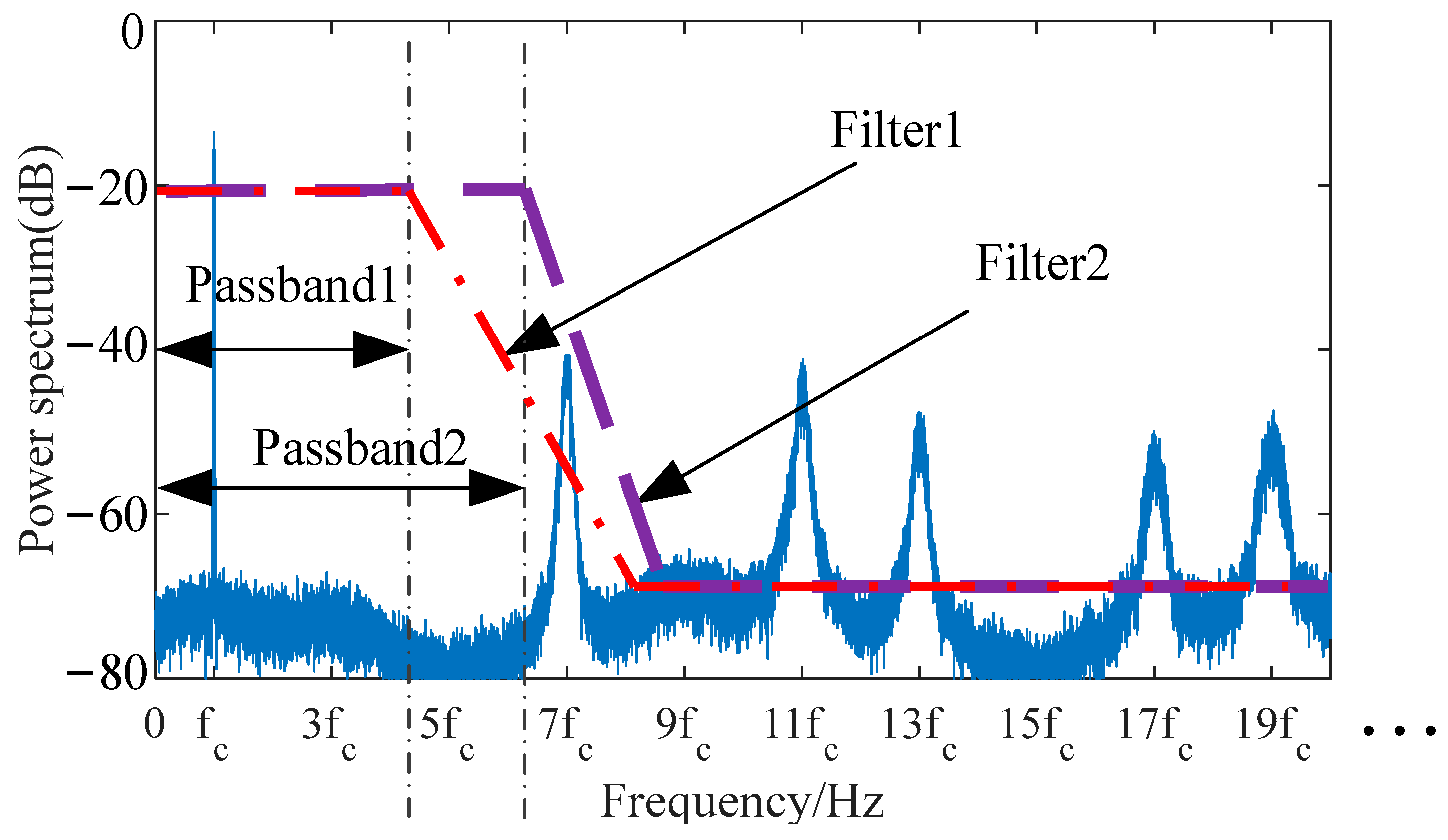
2.1. The Principle of Third and Fifth Harmonic Elimination

The multilevel RF-PWM signal can be obtained by the linear superposition of multiple three-level pulses [5]. The normalized three-level pulse signal waveform q(t) with an arbitrary period of Tc and a pulse width of W is shown in Figure 3, where wc = 2π/Tc is the angular frequency and t0 is the pulse center position. And the three-level pulse q(t) is generated by threshold comparison of threshold signal Vth(t) and reference signal ref(t). A (2m + 1) level RF-PWM signal can be obtained by the linear superposition of m three-level sub-pulse signals qn(t) (n = 1, 2, ..., m), expressed as [21]:
p ( t ) = 1 m n = 1 m k = 1 + 4 sin π k d n π k cos k w c t t n
where k is a positive odd number, dn = Wn/Tc is the duty cycle of the n-th three-level sub-pulse and tn is the pulse center position of the n-th three-level sub-pulse.
By changing the duty cycle dn and the center position tn of the three-level sub-pulse signal qn(t), the fundamental component of the multilevel RF-PWM signal p(t) can be proportional to the input RF signal Sin(t) = a(t)cos[wctφ(t)], and the third and fifth harmonic components are cancelled. The pulse parameters satisfy the equations are as follows:
1 m n = 1 m ε n sin π d n cos w c t t n = c π a t cos w c t φ t / 4 n = 1 m ε n sin 3 π d n cos 3 w c t t n = 0 n = 1 m ε n sin 5 π d n cos 5 w c t t n = 0
where εn = ±1 is the weighting coefficient, the value is determined by the envelope amplitude a(t) of the input signal and c is the gain of the modulator.
In order to simplify the solution of Equation (2), this paper gives a simplified condition which assumes m = 4, t0 = φ(t)/wc, d1 = d3, d2 = d4, t1 = t0 + Δt1, t3 = t0 − Δt1, t2 = t0 + Δt2, t4 = t0 − Δt2. When Δt1 = Δt2 = Δt, Equation (2) can be simplified as
sin π d 1 + d 2 / 2 cos π d 1 d 2 / 2 cos w c Δ t = c π a t / 4 sin 3 π d 1 + d 2 / 2 cos 3 π d 1 d 2 / 2 cos 3 w c Δ t = 0 sin 5 π d 1 + d 2 / 2 cos 5 π d 1 d 2 / 2 cos 5 w c Δ t = 0
According to the periodicity of sine and cosine functions, if sinφ = 0 or cosφ = 0, then sin = 0 or cos = 0 correspondingly, where k is an odd number (k = 1, 3, 5…,). According to Equation (3), when the amplitude of the third and fifth harmonics is zero, the harmonics that are odd multiples of three and five are also cancelled. Therefore, this method can eliminate not only third and five harmonics but also the harmonics that are odd multiples of three and five.
Taking the maximum of the modulator gain c to solve Equation (3), four three-level sub-pulse parameter combinations can be obtained, and these are shown in Table 1. The four parameter combinations can generate two different waveforms. The output waveforms of combinations 1 and 3 are denoted as WI; the output waveforms of combinations 2 and 4 are denoted as WII.
The change of the input signal amplitude a(t) brings the change of the duty cycle of three-level sub-pulses, so that the level number of the multilevel RF-PWM signal synthesized by the superposition of four three-level pulse signals changes. According to the relationship between the pulse width and the pulse center position, the range of the normalized envelope amplitude a(t) under different levels can be calculated.
In the four three-level sub-pulse signals q1(t), q2(t), q3(t) and q4(t), the pulse width of q1(t) and q3(t) is W1 =d1. The pulse width of q2(t) and q4(t) is W2 =d2, and W1 > W2. From the superposition and position relationship of the three-level sub-pulses, and when 0 < W1 ≤ 2Δt, the output signal has three levels; when (W1 + W2)/2 < 2ΔtW1, the output signal has five levels; when W2 < 2Δt ≤ (W1 + W2)/2, the output signal has seven levels; and when 2Δt < W2 ≤ π, the output signal has nine levels. The relationship between the output levels of the two waveforms and the envelope amplitude a(t) is shown in Figure 4. As a(t) increases, the level number of WI and WII gradually increases according to the trend in output signal changing from three levels to five, seven and nine levels.
The three-level sub-pulse qij(t) that meets any combination of pulse parameters in Table 1 can be generated by threshold comparison. After the input signal is normalized, two different reference signals ref1(t) and ref2(t) are obtained according to the pulse center position. The pulse width is determined by the intersection of Vth(t) with ref(t). When |ref(t)| ≤ Vth(t), qij(t) = 0; when ref(t) > Vth(t), qij(t) = 1; and when ref(t) < −Vth(t), qij(t) = −1.
Taking parameter combination 1 as an example, the threshold signal and reference signal can be expressed as follows:
V th 1 = sin 3 π / 10 arccos a t V th 2 = sin 3 π / 10 + arccos a t r e f 1 t = sin w c t φ t π / 6 r e f 2 t = sin w c t φ t + π / 6

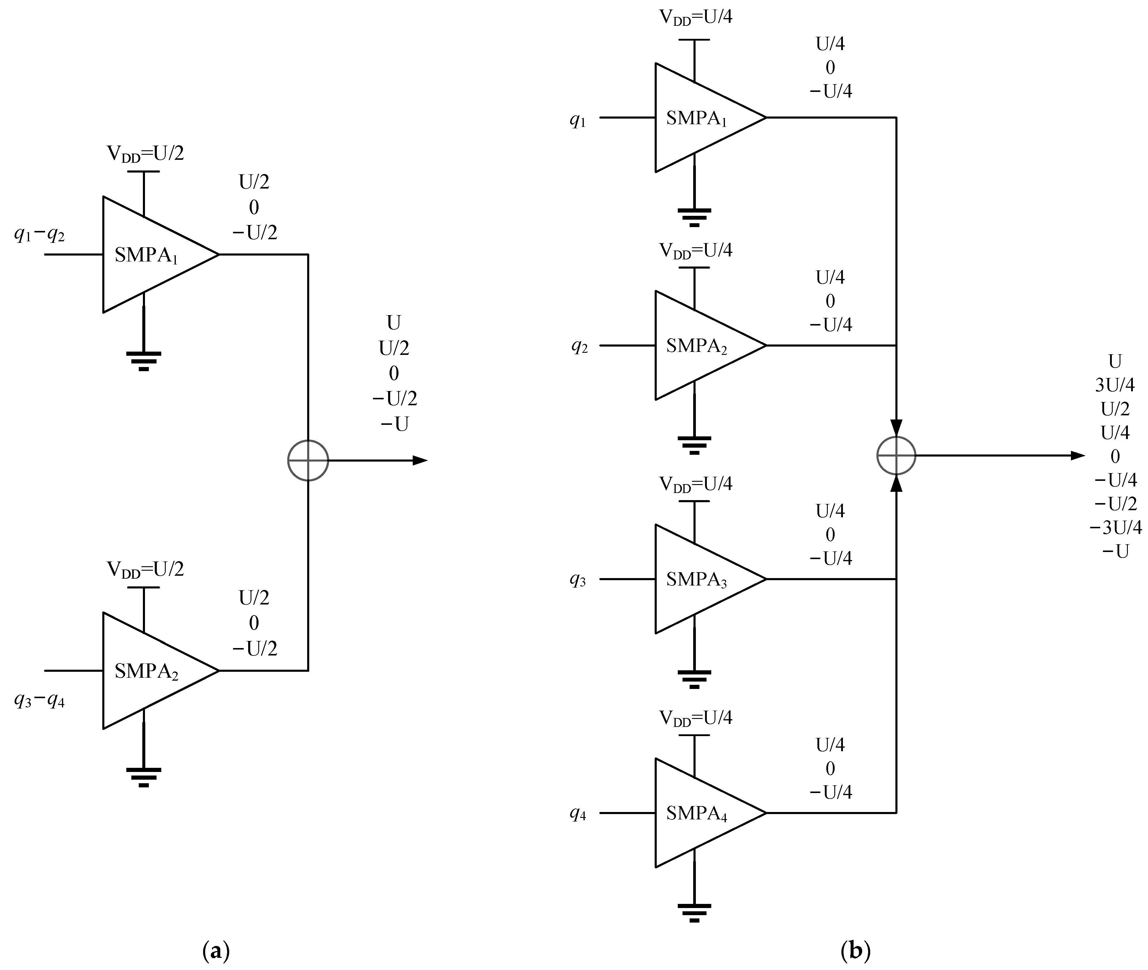
2.2. The Generation of the Five-Level RF-PWM Signal

In order to simplify the output signal from nine levels to five levels, the envelope amplitude a(t) of the normalized signal can be controlled. Thus, the output signal of different levels can be obtained. However, the signal envelope needs to be preprocessed, which complicates the modulator structure. In this paper, by changing the expression of the threshold signal, the coefficient l is added before a(t) in Equation (3), and the threshold signal is expressed as:
V th 1 = sin 3 π / 10 arccos l a t V th 2 = sin 3 π / 10 + arccos l a t
where l is denoted as the attenuation coefficient. For the normalized envelope a(t), the level number of the output signal can be simplified from nine to five by controlling the value of l. As shown in Figure 4, when the output signal is five levels, the adjustable range of the amplitude of WI is larger, so WI is used as the output waveform of the five-level RF-PWM signal, and the range of l is cos(11π/30) ≤ l < cos(π/5). Furthermore, under lower amplitude of a(t), the output five-level signal will degenerate to a three-level signal. When 0 < a(t) ≤ cos(11π/30)/l, the output signal has three levels; when cos(11π/30)/l < a(t) ≤ 1, the output signal has five levels.
The level of the output signal can be adjusted by changing the expression of the threshold signal, which is equivalent to controlling the amplitude of the envelope. Meanwhile, the threshold signal can be obtained through the look-up-table method, which is easier to realize the adjustment of the threshold. Considering the performance of the coding efficiency of the output signal, the method takes the maximum value of l. Thus, a five-level RF-PWM method for the third and fifth harmonic elimination can be obtained.
To generate the five-level RF-PWM signal with third and fifth harmonic elimination, in the structure of the ADTx in Figure 1, the SMPA is composed of two H-bridge class-D SMPA units [22]. Each three-level pulse is efficiently amplified by one SMPA unit. Finally, the modulated five-level RF-PWM signal is output through a series of four SMPA units. As the output RF-PWM signal has five levels, the topological structure of the SMPA is shown in Figure 5. As shown in Figure 5, the maximum voltage of the output signal is denoted as U. Thus, the drive voltage of each SMPA unit in different methods is U/2 and U/4, respectively. In the topological structure of the SMPA under the five-level output signal, the number of SMPA units reduces from 4 to 2, which simplifies the structure of the SMPA. Moreover, the topological structure of SMPA under the nine-level output signal is more complex, requiring higher precision of the voltage U. Therefore, compared with the original RF-PWM method with the third and fifth harmonic elimination, the five-level RF-PWM method can reduce the control complexity of the SMPA.

3. Simulation Results

In order to verify the feasibility of the proposed scheme and analyze its influence on performance, taking the single-tone signal and the complex modulation signal as the input signal, three methods are simulated. Among them, the five-level RF-PWM method with a fixed threshold is denoted as SI, and the values of the fixed thresholds are 0.1 and 0.3. The five-level RF-PWM method of the third harmonic elimination based on the adaptive threshold is denoted as SII. The proposed method is denoted as SIII and the value of l is 0.8.

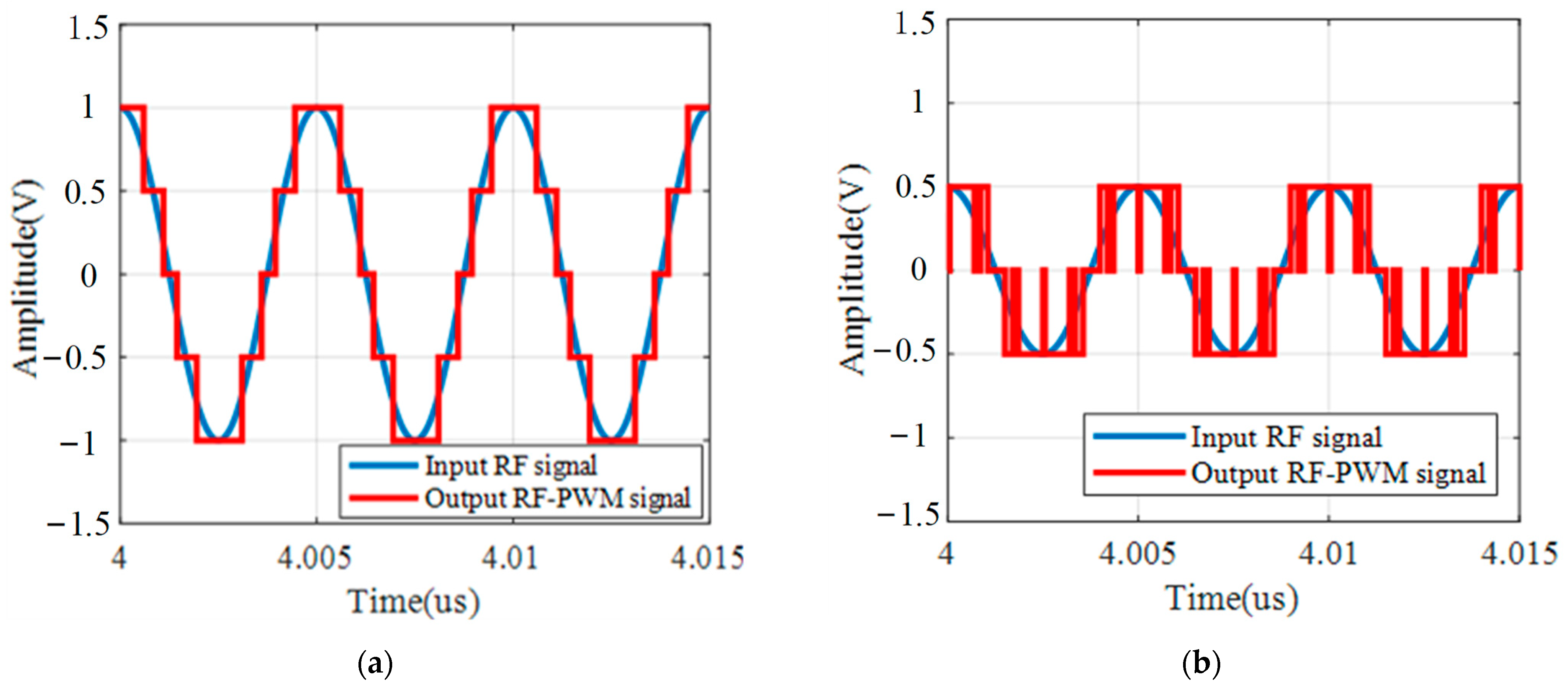
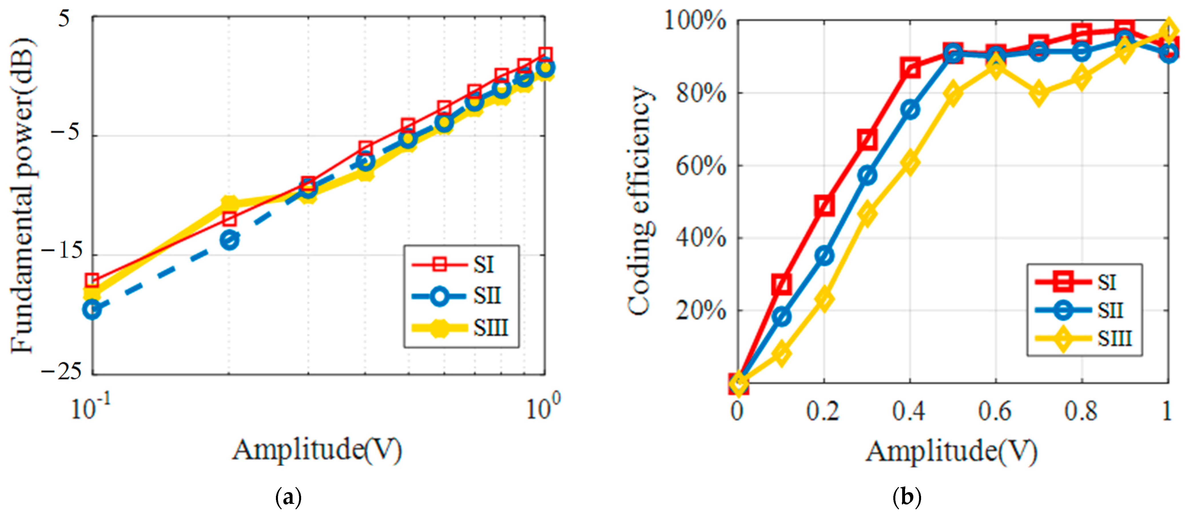
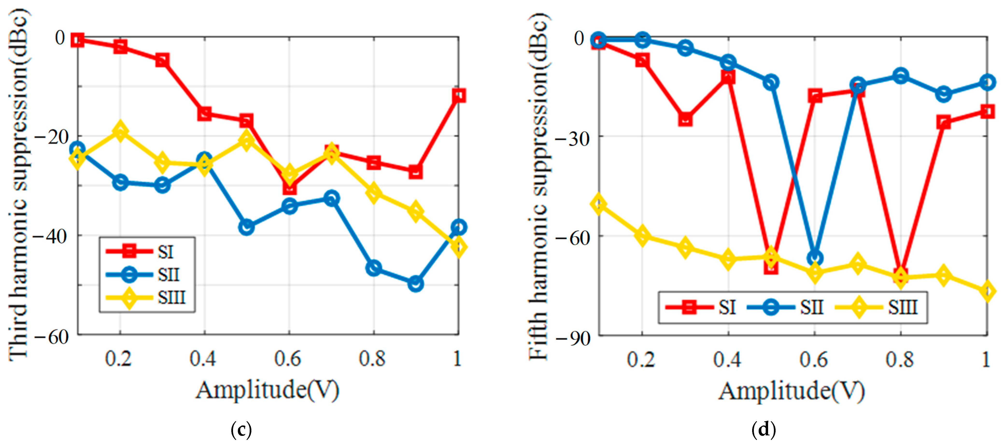
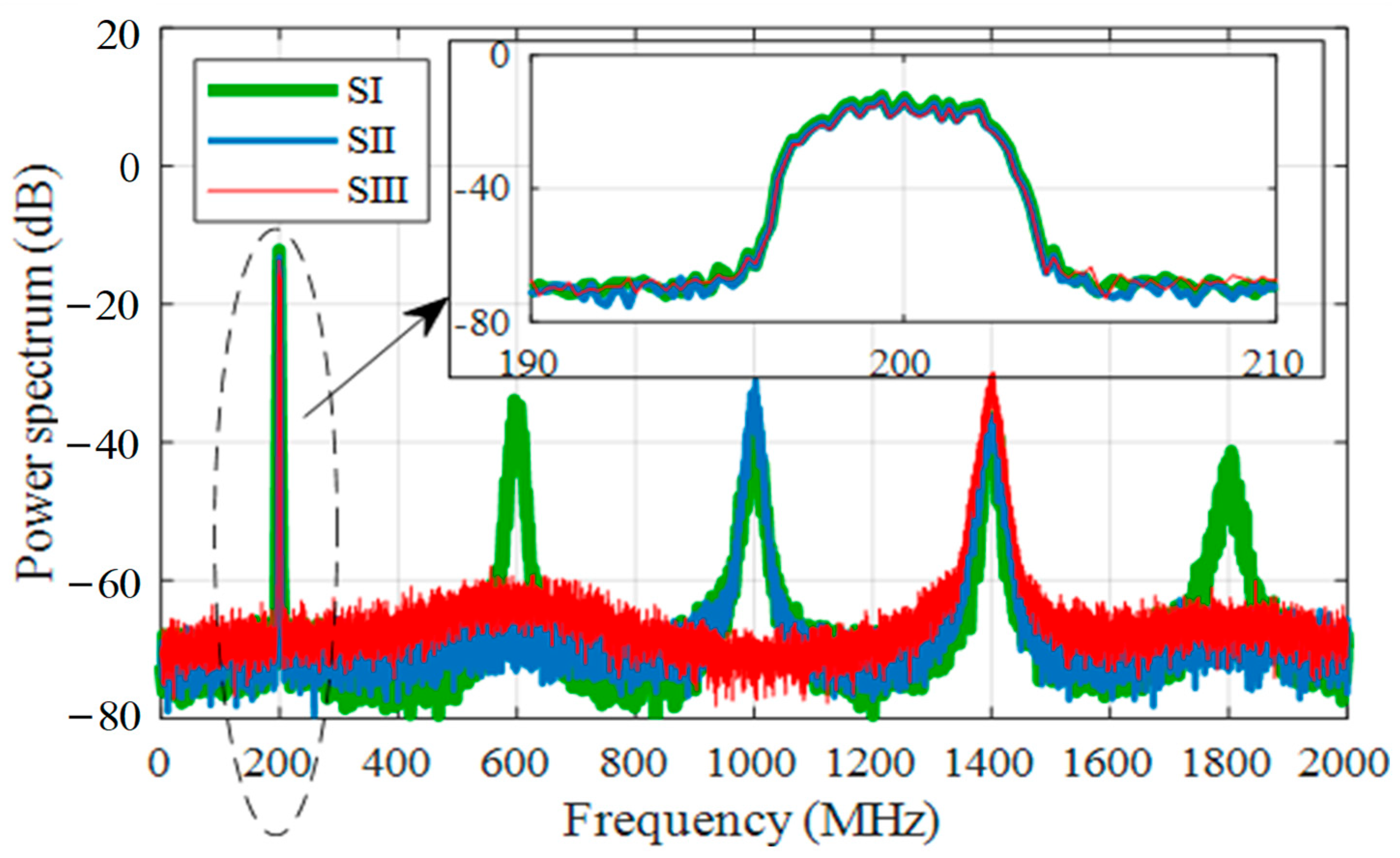
3.1. Simulation Results of the Single-Tone Signal

A single-tone signal with a carrier frequency of 200 MHz is used as the input signal for the simulation implementation of the different schemes. The waveform of the output signal and the input RF signal of SIII under different a(t) are given in Figure 6. When 0.5 < a(t) ≤ 1, the five-level waveform is shown in Figure 6a; when 0 < a(t) ≤ 0.5, the three-level waveform is shown in Figure 6b. As shown in Figure 6a, this method achieves the generation of a five-level RF-PWM signal. The effect of the input signal amplitude on the output performance for the three methods is given in Figure 7. As shown in Figure 7a, SIII has the lowest fundamental power, which is affected by the modulator gain in the method. As shown in Figure 7b, the coding efficiency of SIII is significantly lower than the other two methods, and the decrease in the three-level pulse width brought by the attenuation coefficient in SIII makes the coding efficiency of the output signal lower. As shown in Figure 7c,d, SIII can achieve third and fifth harmonic cancellation, and the third and fifth harmonic suppression effect can reach about −42 dBc and −75 dBc.

3.2. Simulation Results of the 16QAM Signal

To analyze the main output performance of the proposed method under complex modulated signals with variable envelopes, a 16QAM signal with a 200 MHz carrier and a 5.27 dB PAPR is used as the input. The simulated spectrum of the proposed method for the 16QAM input signal at a 200 MHz carrier with Tr = 1%. The harmonics of an odd number from the fundamental component to the 19th harmonic is shown in Figure 8. As shown in Figure 8, the third and fifth harmonics and the harmonics that are odd multiples of three and five are eliminated. Moreover, the amplitude of odd number harmonics decreases as the number of harmonics increases. The bandwidth of filters is also compared in the simulated spectrum, and the proposed method has a great improvement in filter bandwidth. The spectrums of the three methods are given in Figure 9. Compared with SI and SII, SIII achieves the third and fifth harmonic elimination, and the performance comparison is given in Table 2. The coding efficiency of SIII is lower than that of SI and SII by about 9.5% and 13.8%, respectively, while the fifth harmonic cancellation effect of SIII can reach about −54 dBc. Finally, the ACPR of SIII is also reduced by about 3 dBc. Therefore, SIII has a better third and fifth harmonic-elimination effect with other performances than existing methods.

4. Conclusions

This paper proposes a five-level RF-PWM method with third and fifth harmonic cancellation. Based on the multilevel RF-PWM scheme with third and fifth harmonic cancellation, the output signal is simplified from nine levels to the five levels by changing the expression of the threshold signal. Furthermore, the voltage control complexity of the SMPA is obviously reduced by the decrease in the output-signal-level number. Taking the output waveform WI as an example, the threshold signal is determined by the attenuation coefficient of WI. For a 16QAM signal with a 200 MHz carrier and a 5.27 dB PAPR, the proposed method has a good third and fifth harmonic-suppression effect. Meanwhile, the coding efficiency and ACPR are reduced in comparison with existing methods. Therefore, this method is a compromise between harmonic elimination and code efficiency.
In addition, this paper also presents that the input envelope signal a(t) has an influence on the output performance. In further research, the influence from different output waveforms and the PAPR of complex modulated signals on the output performance will be the key subject.

Author Contributions

H.F. and Q.Z. proposed the method and was in charge of review and editing. H.F. completed the theoretical derivation and wrote the manuscript. H.F., L.Z. and Z.C. wrote the MATLAB program to implement the method and completed the simulation. Z.W. and S.Z. assisted in the implementation of this method and analyzed the simulation data. Q.Z. was the project administrator. All authors have read and agreed to the published version of the manuscript.

Funding

This work was funded by the Key Program of National Science Foundation of China (Grant 61631021).

Institutional Review Board Statement

Not applicable.

Informed Consent Statement

Not applicable.

Data Availability Statement

Not applicable.

Conflicts of Interest

The authors declare no conflict of interest.

References

  1. Prata, A.; Cordeiro, R.F.; Dinis, D.C.; Oliveira, A.S.R.; Vieira, J.; Carvalho, N.B. All-digital transceivers—Recent advances and trends. In Proceedings of the IEEE International Conference on Electronics, Circuits and Systems, Monte Carlo, Monaco, 11–14 December 2016. [Google Scholar]
  2. Nuyts, P.A.J.; Reynaert, P.; Dehaene, W. Frequency-domain analysis of digital PWM-based RF modulators for flexible wireless transmitters. IEEE Trans. Circuits Syst. I Regul. Pap. 2014, 61, 238–246. [Google Scholar] [CrossRef]
  3. Yang, S.Y.; Yang, J.; Huang, L.Y.; Bai, J.L.; Zhang, X.Y. A Dual-Band RF All-Digital Transmitter Based on MPWM Encoding. IEEE Trans. Microw. Theory Tech. 2022, 70, 1745–1756. [Google Scholar] [CrossRef]
  4. Dinis, D.C.; Rui, F.C.; Oliveira, A.S.R. A fully parallel architecture for designing frequency-agile and real-time reconfigurable FPGA-based RF digital transmitters. IEEE Trans. Microw. Theory Tech. 2018, 66, 1489–1499. [Google Scholar] [CrossRef]
  5. Yao, F.; Zhou, Q.; Wei, Z. A novel multilevel RF-PWM method with active-harmonic elimination for all-digital transmitters. IEEE Trans. Microw. Theory Tech. 2018, 66, 3360–3373. [Google Scholar] [CrossRef]
  6. Nuyts, P.A.J.; Reynaert, P.; Dehaene, W. A fully digital PWM based 1 to 3 GHz multistandard transmitter in 40-nm CMOS. In Proceedings of the 2013 IEEE Radio Frequency Integrated Circuits Symposium, Seattle, WA, USA, 2–4 June 2013. [Google Scholar]
  7. Chen, Z.; Yang, J.; Zhang, X.; Bai, J.; Feng, T.; Tang, J.; Chen, G.; Jiang, Z. Mathematical Model and Reference Frequency Optimization for Digital Dual-Band Pulsewidth Modulation. In Proceedings of the IEEE MTT-S International Wireless Symposium, Shanghai, China, 20–23 September 2020. [Google Scholar]
  8. Yang, S.Y.; Yang, J.; Zhao, J.; Zhang, X.Y. Clean bandwidth improvement of MPWM encoding method for RF all-digital transmitter. IEEE Trans. Circuits Syst. II Exp. Briefs 2021, 68, 2404–2408. [Google Scholar] [CrossRef]
  9. Silva, N.V.; Oliveira, A.S.R.; Carvalho, N.B. Design and optimization of flexible and coding efficient all-digital RF transmitters. IEEE Trans. Microw. Theory Tech. 2013, 61, 625–632. [Google Scholar] [CrossRef]
  10. Raab, F.H. Radio frequency pulsewidth modulation. IEEE Trans. Commun. 1973, 21, 958–966. [Google Scholar] [CrossRef]
  11. Pasha, M.T.; Haque, M.F.U.; Ahmad, J.; Johansson, T. A Modified All-Digital Polar PWM Transmitter. IEEE Trans. Circuits Syst. I Regul. Pap. 2018, 65, 758–768. [Google Scholar] [CrossRef]
  12. Kulkarni, S.; Kazi, I.; Seebacher, D.; Singerl, P.; Dielacher, F.; Dehaene, W.; Reynaert, P. Multi-standard wideband OFDM RF-PWM transmitter in 40 nm CMOS. In Proceedings of the IEEE European Solid-State Circuits Conference, Graz, Austria, 14–18 October 2015. [Google Scholar]
  13. Huhn, F.; Wentzel, A.; Heinrich, W. A Reconfigurable Modulator for Digital Outphasing Transmitters. In Proceedings of the IEEE MTT-S International Microwave Symposium, Boston, MA, USA, 2–7 June 2019. [Google Scholar]
  14. Chierchie, F.; González, G.J.; Morales, J.I.; Paolini, E.E.; Cousseau, J.; Mandolesi, P.S. Baseband Model for Uniformly Sampled RF-PWM. IEEE Trans. Circuits Syst. I Regul. Pap. 2020, 67, 2816–2824. [Google Scholar] [CrossRef]
  15. Cho, K.; Gharpurey, R. A 25.6 dBm wireless transmitter using RF-PWM with carrier switching in 130-nm CMOS. In Proceedings of the IEEE Radio Frequency Integrated Circuits Symposium, Phoenix, AZ, USA, 17–19 May 2015. [Google Scholar]
  16. Francois, B.; Nuyts, P.A.J.; Dehaene, W.; Reynaert, P. Extending dynamic range of RF PWM transmitters. Electron. Lett. 2013, 49, 430–432. [Google Scholar] [CrossRef]
  17. Zhu, Q.; Ma, R.; Duan, C.; Teo, K.H.; Parsons, K. A 5-level discrete-time power encoder with measured coding efficiency of 70% for 20-MHz LTE digital transmitter. In Proceedings of the IEEE MTT-S International Microwave Symposium Digest, Tampa, FL, USA, 1–6 June 2014. [Google Scholar]
  18. Yang, K.; Zhang, Q.; Zhang, J.; Yuan, R.; Guan, Q.; Yu, W.; Wang, J. Unified Selective Harmonic Elimination for Multilevel Converters. IEEE Trans. Power Electron. 2017, 32, 1579–1590. [Google Scholar] [CrossRef]
  19. El Houda Gabour, N.; Habbi, F.; Bounekhla, M.; Boudissa, E.G. Enhanced Harmonic Elimination Using Genetic Algorithm Optimization in Multilevel Inverters. In Proceedings of the IEEE International Multi-Conference on Systems, Signals and Devices, SSD, Monastir, Tunisia, 22–25 March 2021. [Google Scholar]
  20. Sulong, M.M.S.; Saifizi, M.; Mustafa, W.A.; Aihsan, M.Z. Harmonic Elimination Simulation of Seven Level Cascaded H-Bridge Inverter Based on Newton Raphson Method. In Proceedings of the 12th National Technical Seminar on Unmanned System Technology 2020; Springer: Singapore, 2020. [Google Scholar]
  21. Fu, H.; Zhou, Q.; Zhu, L.; Wei, Z.; Zhang, J. A Pulse Waveform Control Method for Multiple Harmonic Elimination of Multilevel RF-PWM. In Proceedings of the IEEE MTT-S International Wireless Symposium, Harbin, China, 12–15 August 2022. [Google Scholar]
  22. Lai, L.; Zhang, R.; Cheng, K.; Xia, Z.; Wei, C.; Wei, K.; Luo, W.; Liu, X. Monolithic Integrated High Frequency GaN DC-DC Buck Converters with High Power Density Controlled by Current Mode Logic Level Signal. Electronics 2020, 9, 1540. [Google Scholar] [CrossRef]
Figure 1. Diagram of ADTx structure based on RF-PWM.
Electronics 11 03257 g001
Figure 2. The profile of harmonics when third and fifth harmonics are eliminated in proposed method. In this paper, a five-level RF-PWM method for broadband ADTx is proposed. The method achieves the third and fifth harmonic cancellation of five-level RF-PWM by controlling the pulse width and the center position of the three-level sub-pulses the generation of the five-level RF-PWM signal by changing the threshold signals. Compared with existing RF-PWM methods, the method proposed in this paper can achieve simultaneous elimination of the third and fifth harmonics, relax the requirement for output filters and improve the broadband performance of ADTx.
Electronics 11 03257 g002
Figure 3. Diagram of any three-level pulse with threshold comparison.
Electronics 11 03257 g003
Figure 4. Diagram of the relationship between the number of levels and a(t).
Electronics 11 03257 g004
Figure 5. The circuit topological structure of SMPA when the output pulse is (a) five-level RF-PWM signal (b) nine-level RF-PWM signal, under the same maximum of output voltage.
Electronics 11 03257 g005
Figure 6. Waveforms of the RF input and output signals under SIII when (a) a(t) = 1 (b) a(t) = 0.5, with the input single-tone signal at a 200 MHz carrier.
Electronics 11 03257 g006
Figure 7. Simulated characteristics of SI, SII and SIII with the single-tone signal under different amplitude at 200 MHz carrier with Tr = 1% (a) Fundamental power. (b) Coding efficiency. (c) Third harmonic suppression. (d) Fifth harmonic suppression.
Electronics 11 03257 g007aElectronics 11 03257 g007b
Figure 8. Simulated spectrum of the proposed method for the 16QAM input signal at 200 MHz carrier with Tr = 1%.
Electronics 11 03257 g008
Figure 9. Simulated spectrum of SI, SII and SIII for the 16QAM input signal at 200 MHz carrier with Tr = 1%.
Electronics 11 03257 g009
Table 1. Parameter Groups of Three-Level Pulses When Δt1 = Δt2.
Parameters
of Sub-Pulses
Simplified
Conditions
Parameter
Combination 1
Parameter
Combination 2
Parameter
Combination 3
Parameter
Combination 4
Center positiont1 = t2φ(t)/wc + Tc/12φ(t)/wc Tc/12φ(t)/wc + 3Tc/20φ(t)/wc + Tc/20
t3 = t4φ(t)/wc − Tc/12φ(t)/wc − Tc/12φ(t)/wc3Tc/20φ(t)/wc − Tc/20
Duty-cycled1 = d31/5 + arccos(a(t))/π2/5 + arccos(a(t))/π1/3 + arccos(a(t))/π1/3 + arccos(a(t))/π
d2 = d41/5 – arccos(a(t))/π2/5 – arccos(a(t))/π1/3 – arccos(a(t))/π1/3 – arccos(a(t))/π
Table 2. Performance Comparison for SI, SII and SIII under the 16QAM Input Signal at 200 MHz Carrier with Tr = 1%.
PerformanceSISIISIII
Fundamental power (dB)−6.45−7.41−7.97
Coding Efficiency (%)89.9585.6977.51
Third harmonic suppression(dBc)−22.90−51.99−46.24
Fifth harmonic suppression(dBc)−25.60−18.43−54.05
ACPR (dBc)−50.27−50.44−47.87
EVM (%)0.840.810.87
Publisher’s Note: MDPI stays neutral with regard to jurisdictional claims in published maps and institutional affiliations.

