Author Contributions
Conceptualization, G.-M.S., L.-F.T., C.-C.H. and H.-Y.H.; methodology, L.-F.T. and H.-Y.H.; formal analysis, L.-F.T., C.-C.H. and H.-Y.H.; investigation, L.-F.T. and H.-Y.H.; writing—review and editing, G.-M.S., L.-F.T., C.-C.H. and H.-Y.H.; supervision, G.-M.S. and L.-F.T.; project administration, G.-M.S.; funding acquisition, G.-M.S. All authors have read and agreed to the published version of the manuscript.
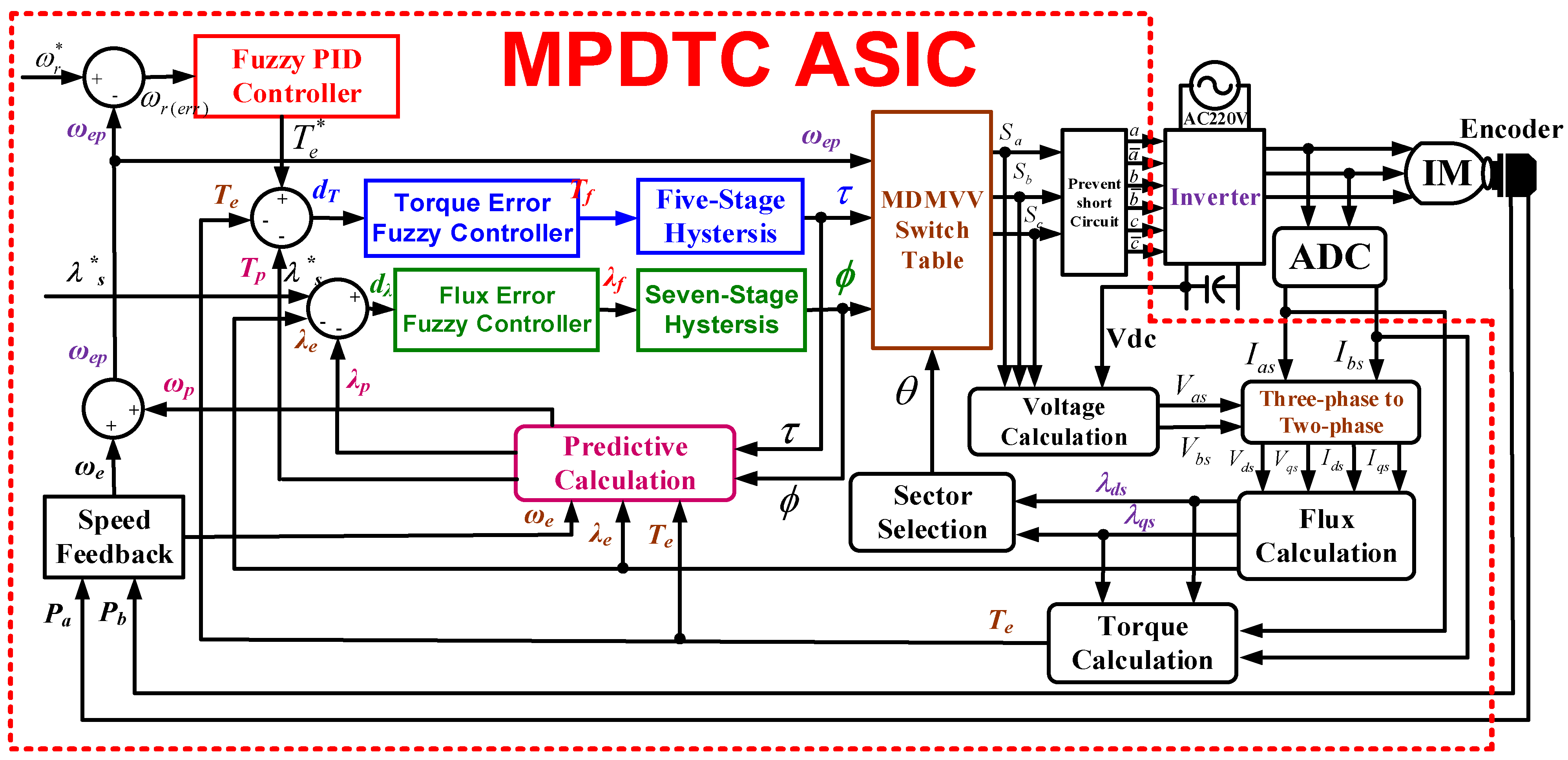
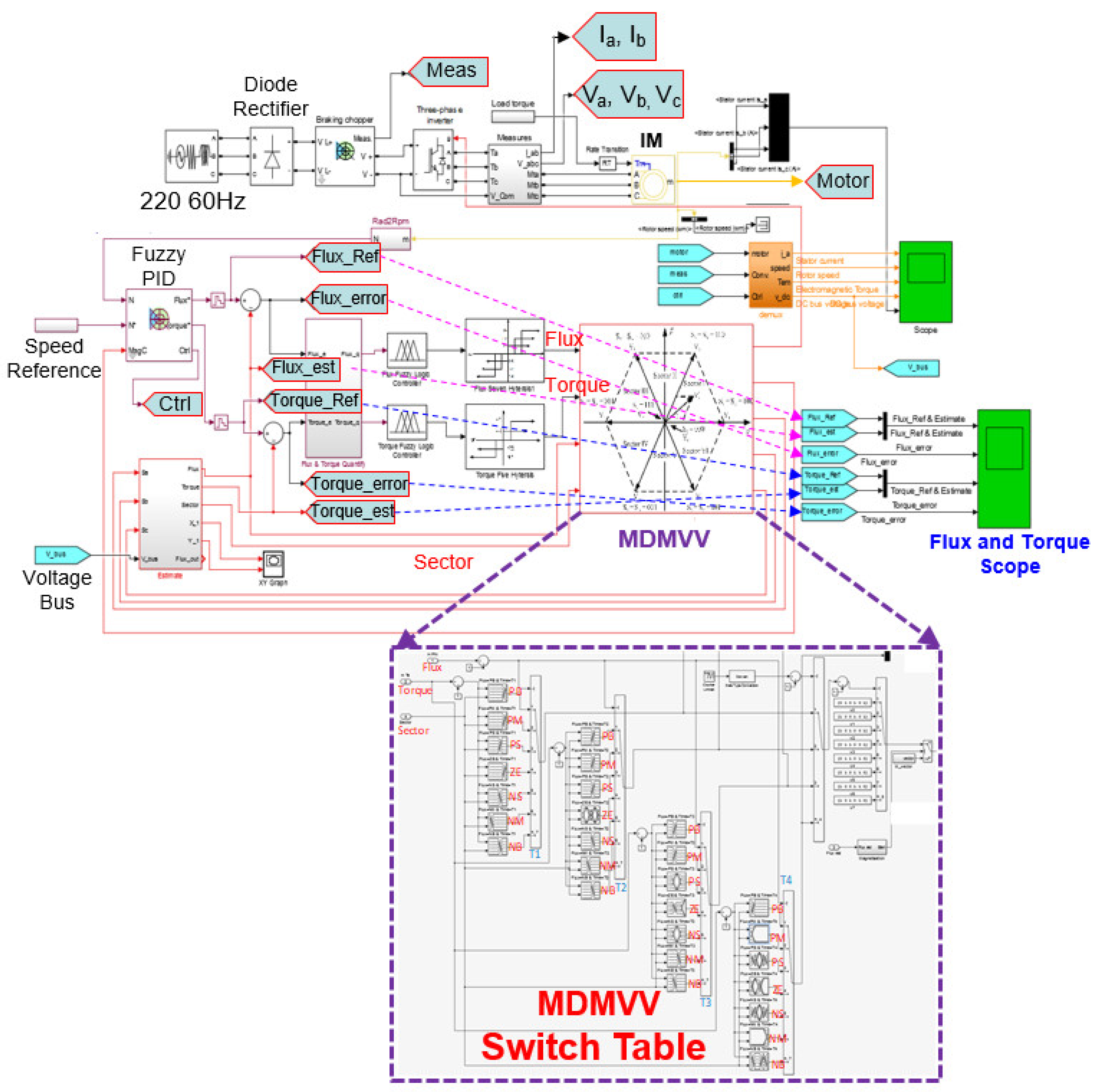
Figure 1.
Block diagram of the proposed MPDTC ASIC with fuzzy seven-stage hysteresis and a fuzzy PID controller for s a three-phase IM drive system.
Figure 1.
Block diagram of the proposed MPDTC ASIC with fuzzy seven-stage hysteresis and a fuzzy PID controller for s a three-phase IM drive system.
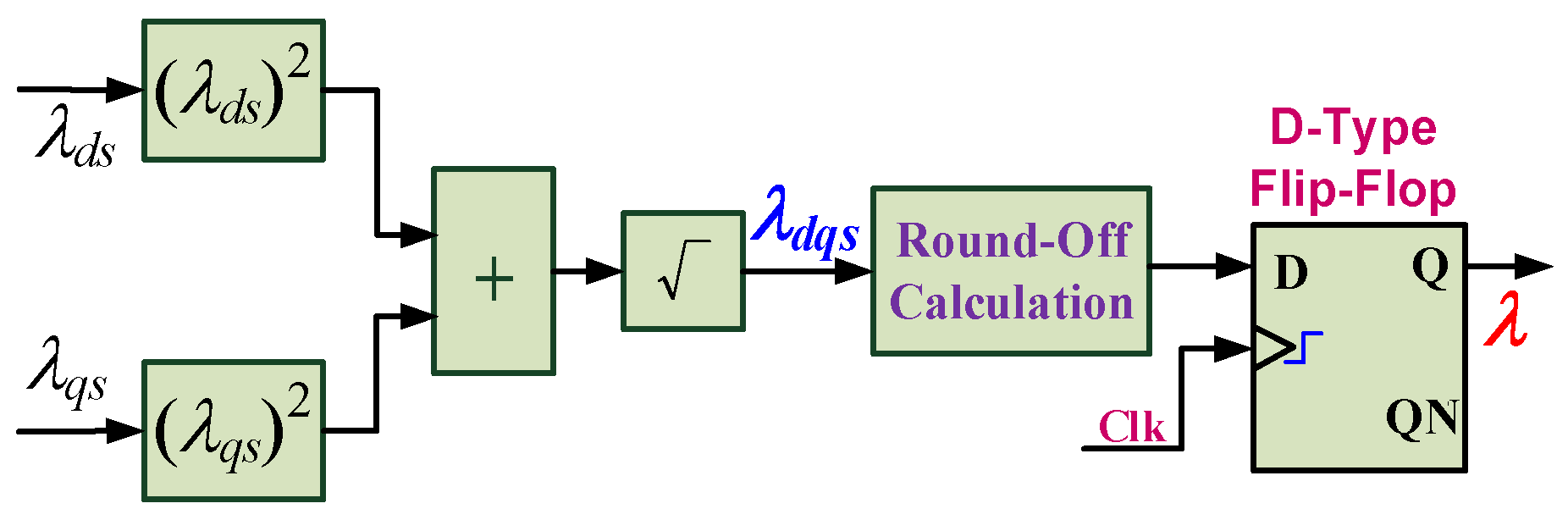
Figure 2.
Calculation blocks of the synthetic flux with square root, round-off calculation, and DFF circuits.
Figure 2.
Calculation blocks of the synthetic flux with square root, round-off calculation, and DFF circuits.
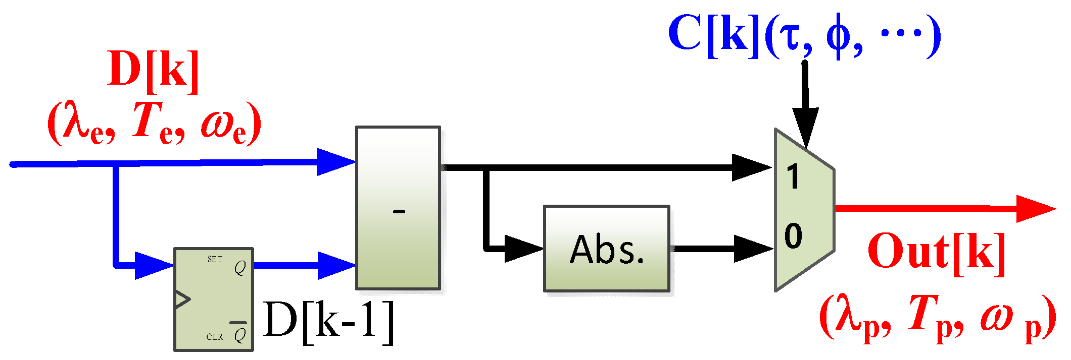
Figure 3.
Block diagram of the predictive control model with input flux error (λe), torque error (Te), and speed error (ωe).
Figure 3.
Block diagram of the predictive control model with input flux error (λe), torque error (Te), and speed error (ωe).
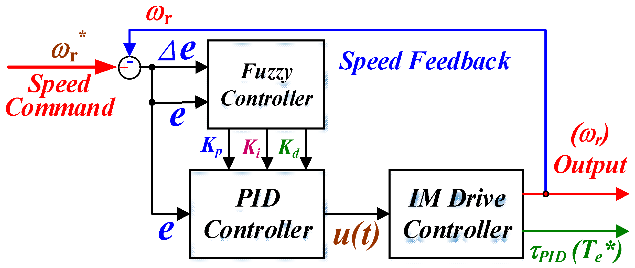
Figure 4.
Block diagram of a fuzzy PID controller.
Figure 4.
Block diagram of a fuzzy PID controller.
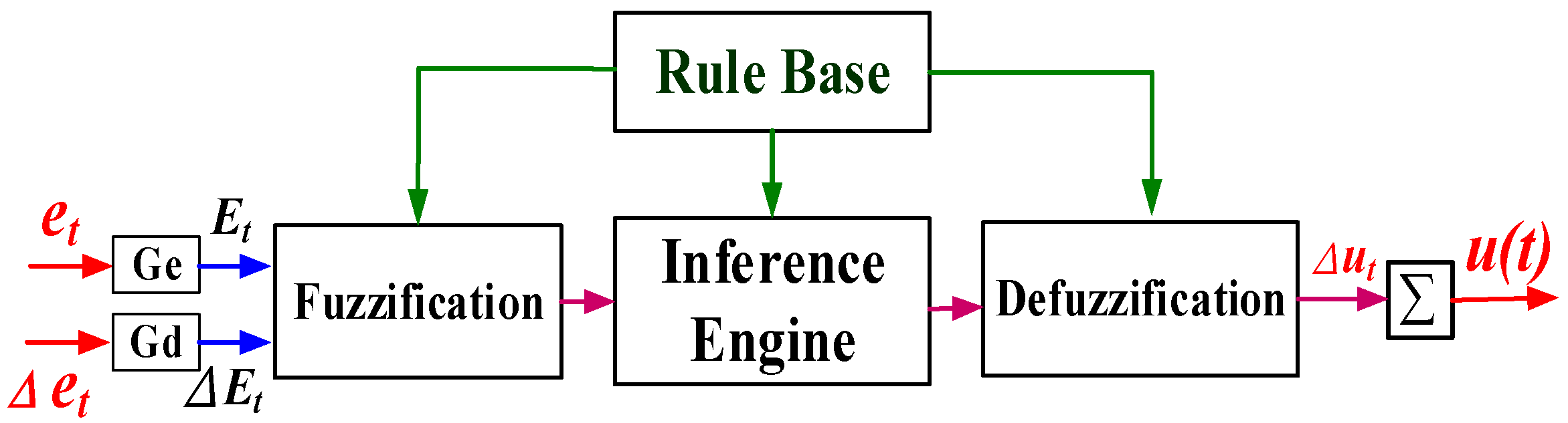
Figure 5.
Block diagram of the error fuzzy controller.
Figure 5.
Block diagram of the error fuzzy controller.
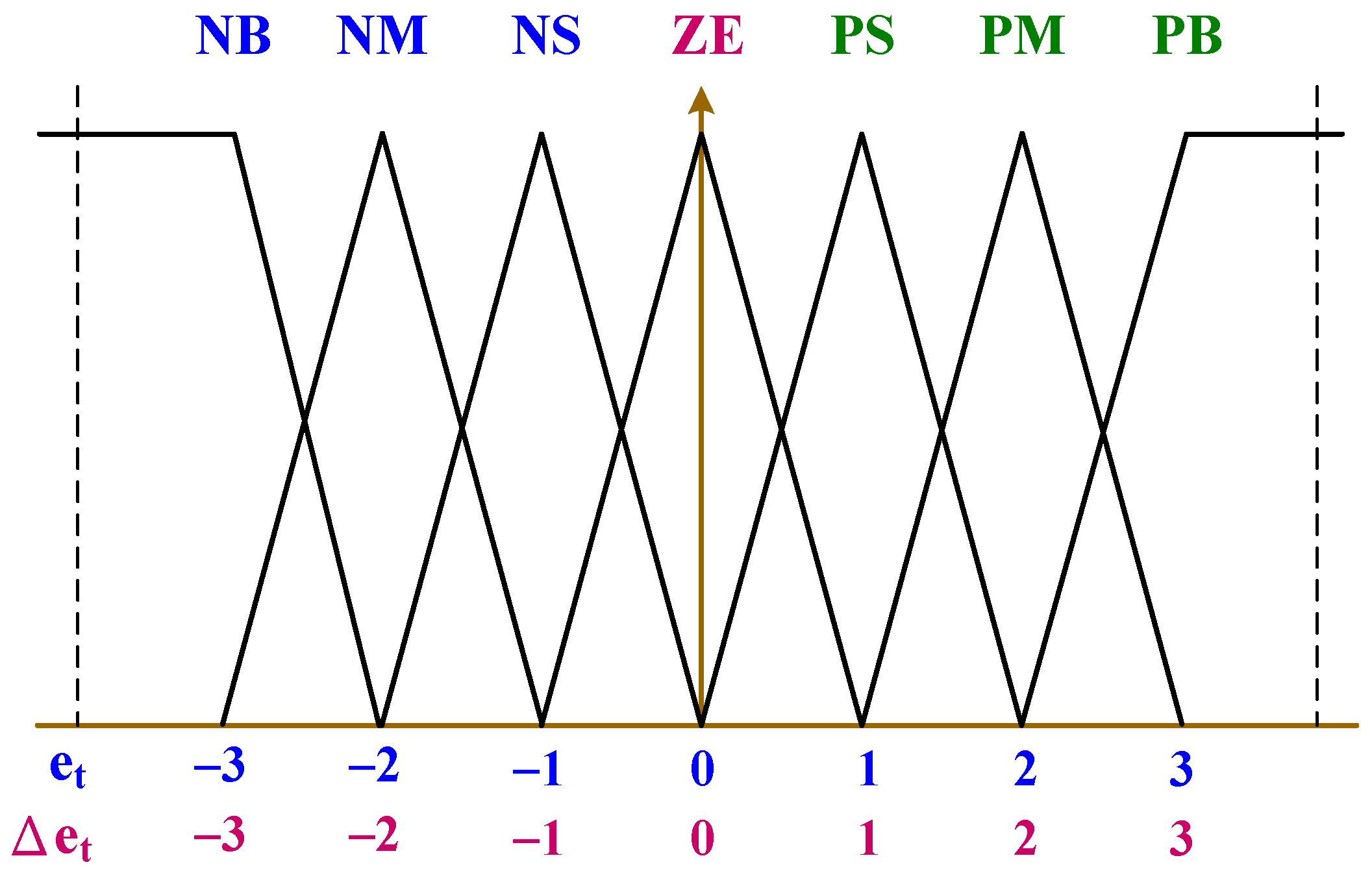
Figure 6.
Seven–stage fuzzy membership function.
Figure 6.
Seven–stage fuzzy membership function.
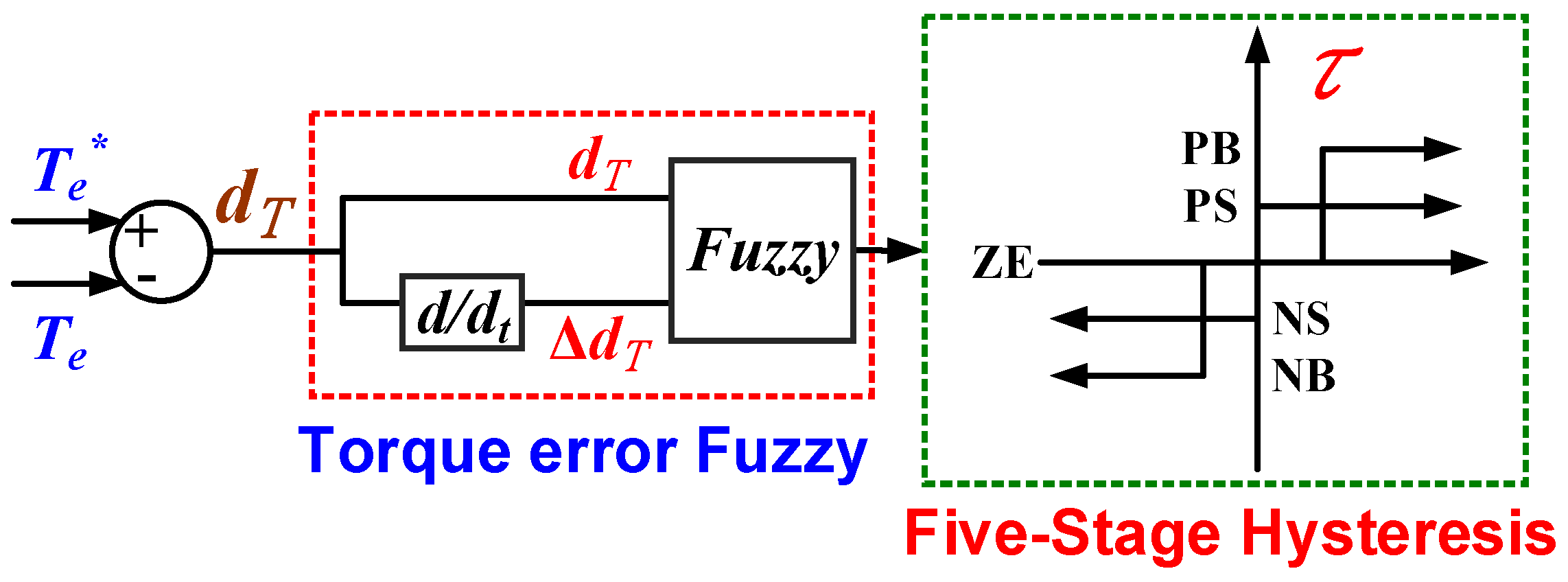
Figure 7.
Torque error fuzzy controller with five-stage hysteresis control.
Figure 7.
Torque error fuzzy controller with five-stage hysteresis control.
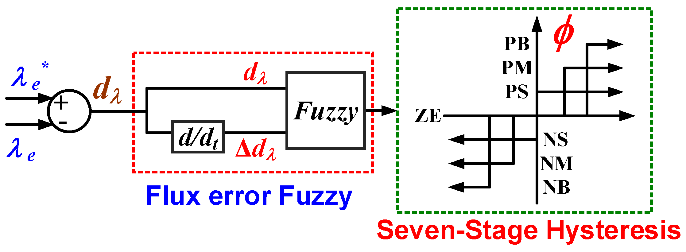
Figure 8.
Flux error fuzzy controller with seven-stage hysteresis control.
Figure 8.
Flux error fuzzy controller with seven-stage hysteresis control.
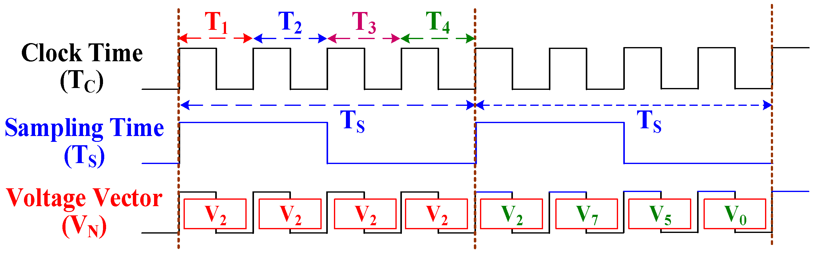
Figure 9.
Time sequence of the MDMVV for the stator torque.
Figure 9.
Time sequence of the MDMVV for the stator torque.
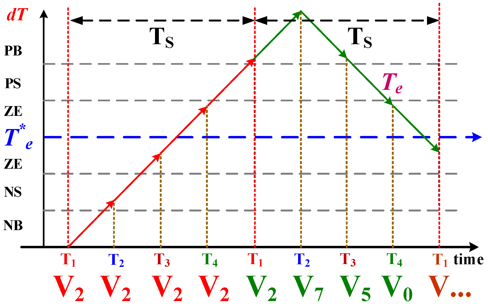
Figure 10.
Variation in dT with sampling time (Ts), which is equal to four times clock time TC.
Figure 10.
Variation in dT with sampling time (Ts), which is equal to four times clock time TC.
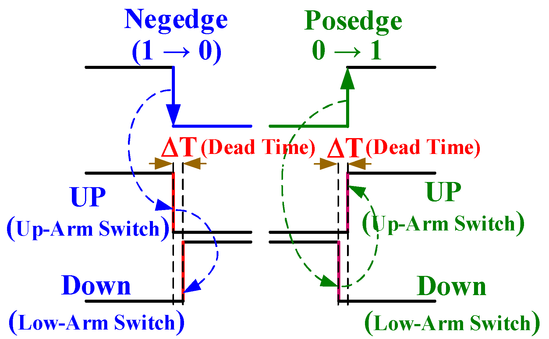
Figure 11.
Proposed short-circuit prevention scheme.
Figure 11.
Proposed short-circuit prevention scheme.
Figure 12.
Functional simulation chart of the proposed MPDTC system for a three-phase IM drive.
Figure 12.
Functional simulation chart of the proposed MPDTC system for a three-phase IM drive.
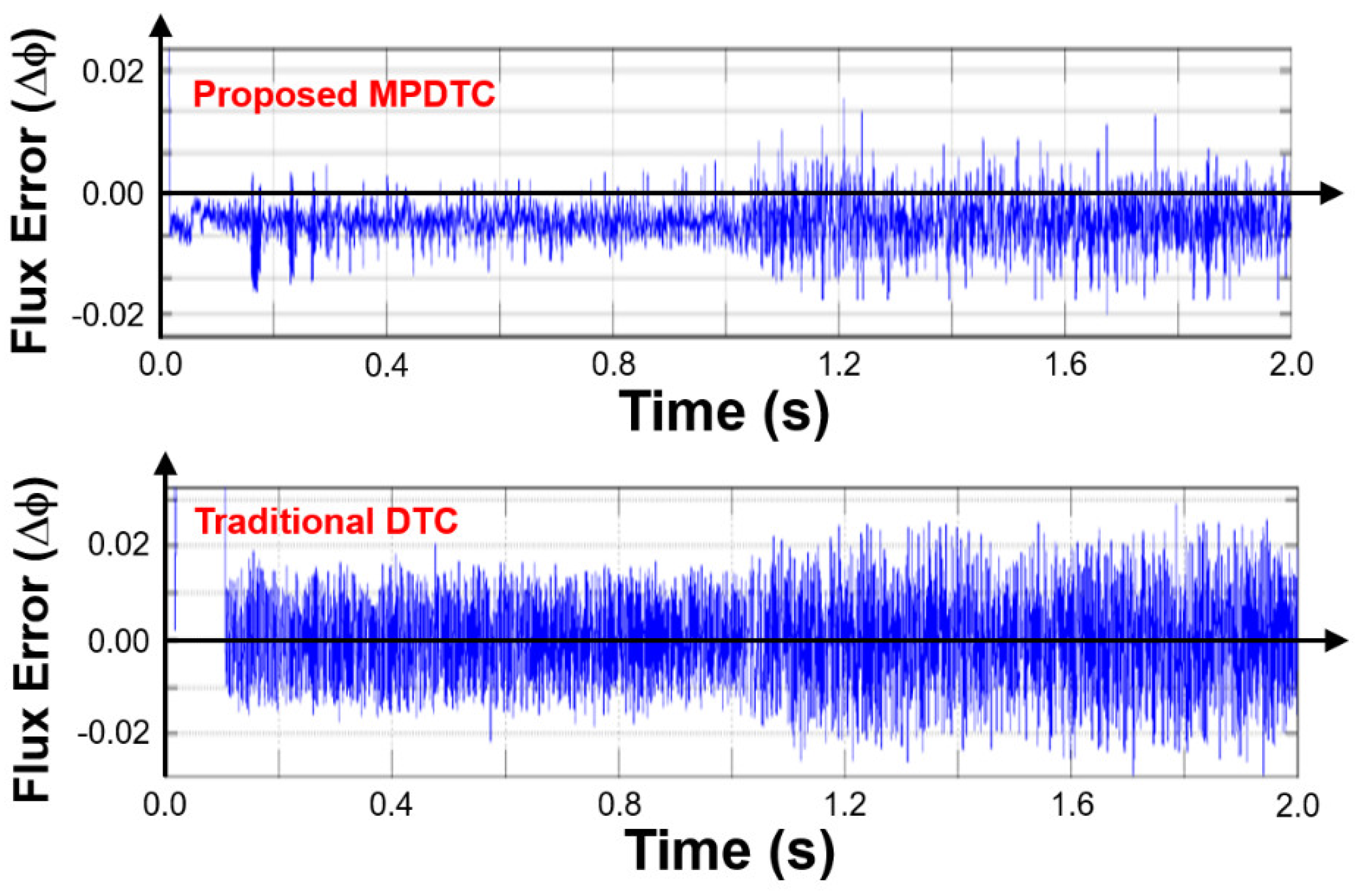
Figure 13.
Simulated flux errors of the proposed MPDTC and traditional DTC systems between 0 and 2 s.
Figure 13.
Simulated flux errors of the proposed MPDTC and traditional DTC systems between 0 and 2 s.
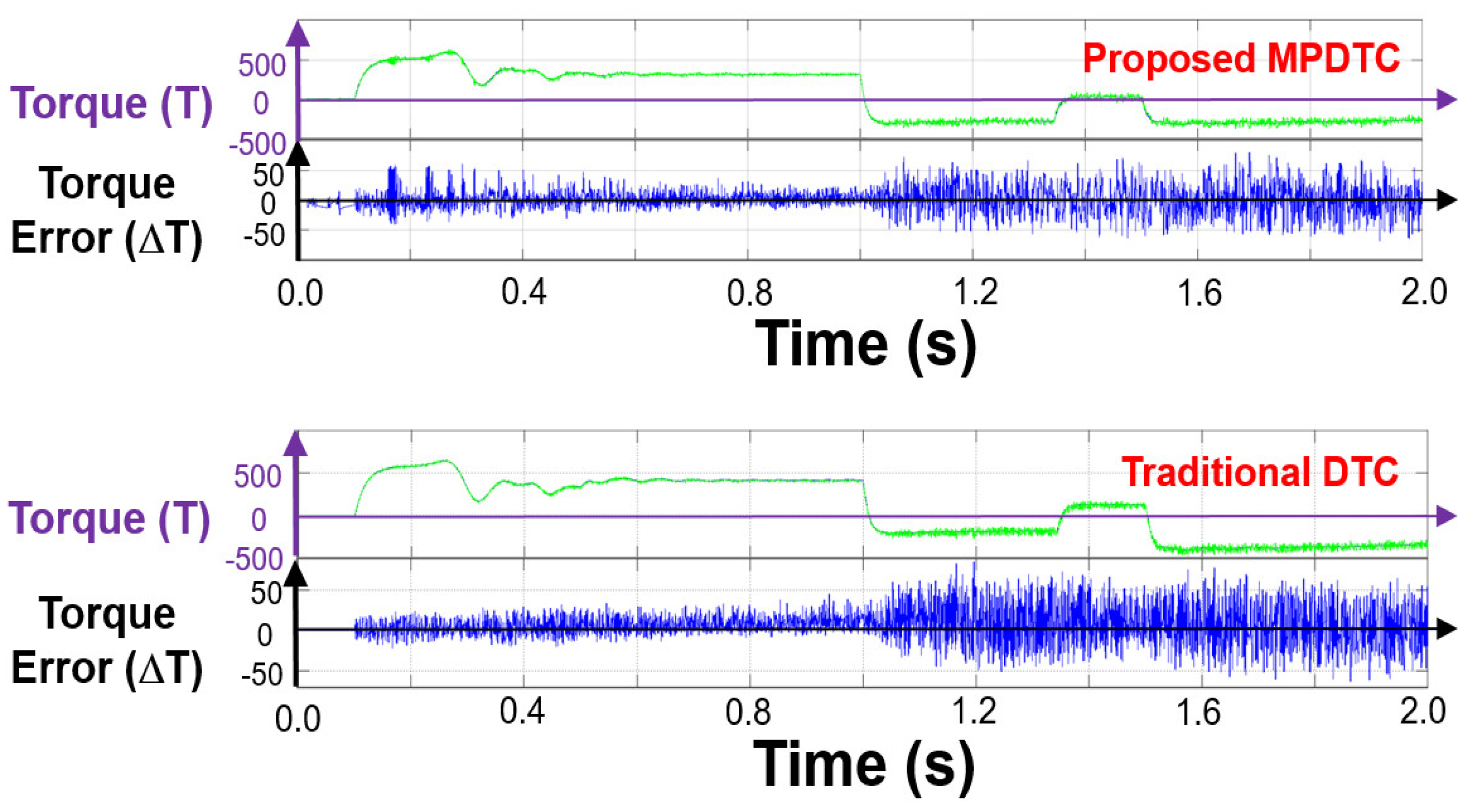
Figure 14.
Simulated torque errors of the proposed MPDTC and traditional DTC systems between 0 and 2 s.
Figure 14.
Simulated torque errors of the proposed MPDTC and traditional DTC systems between 0 and 2 s.
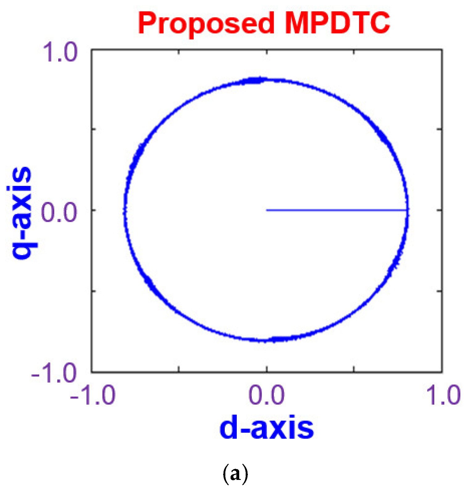
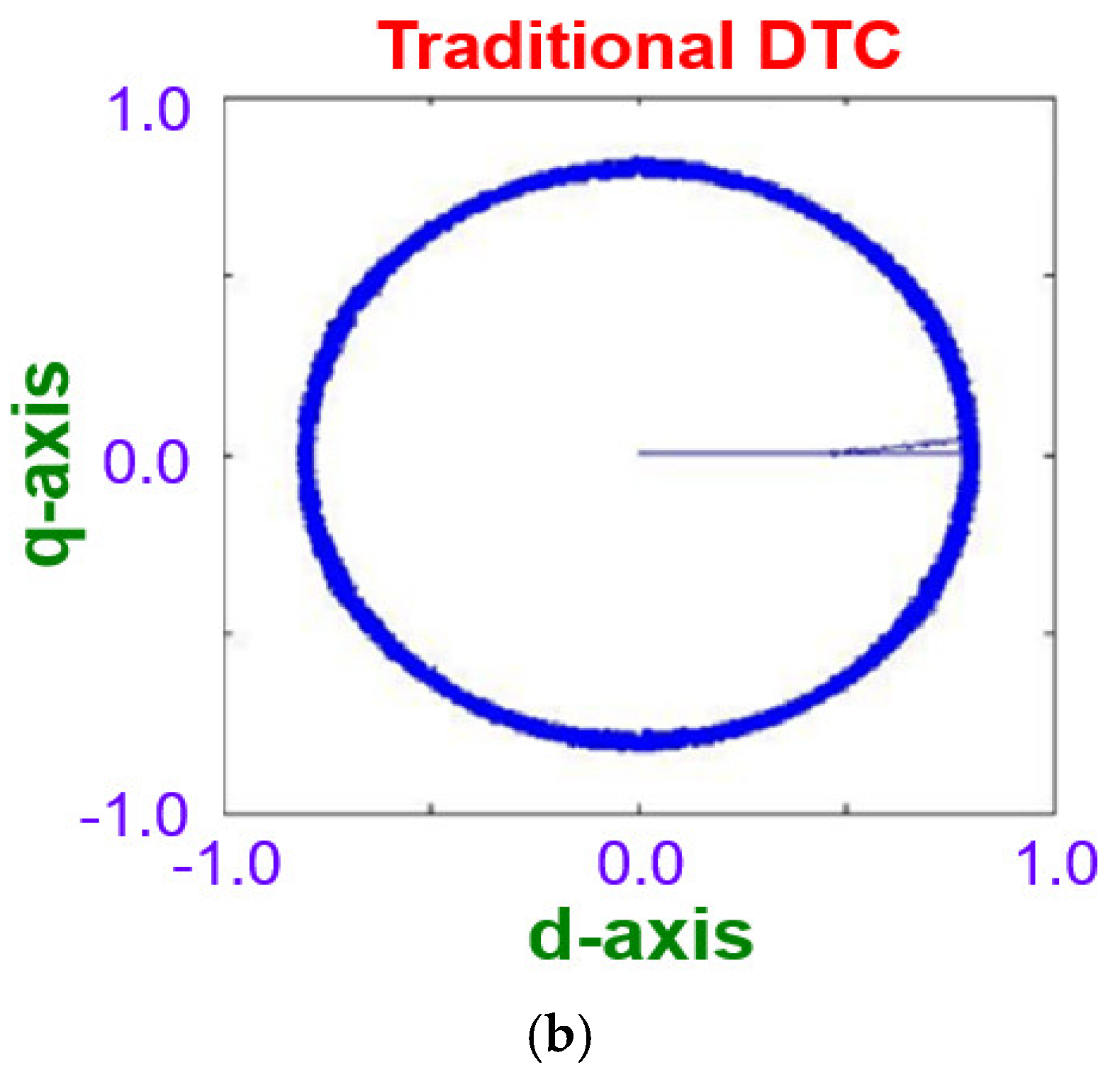
Figure 15.
Simulated stator flux trajectory of (a) proposed MPDTC and (b) traditional DTC systems.
Figure 15.
Simulated stator flux trajectory of (a) proposed MPDTC and (b) traditional DTC systems.
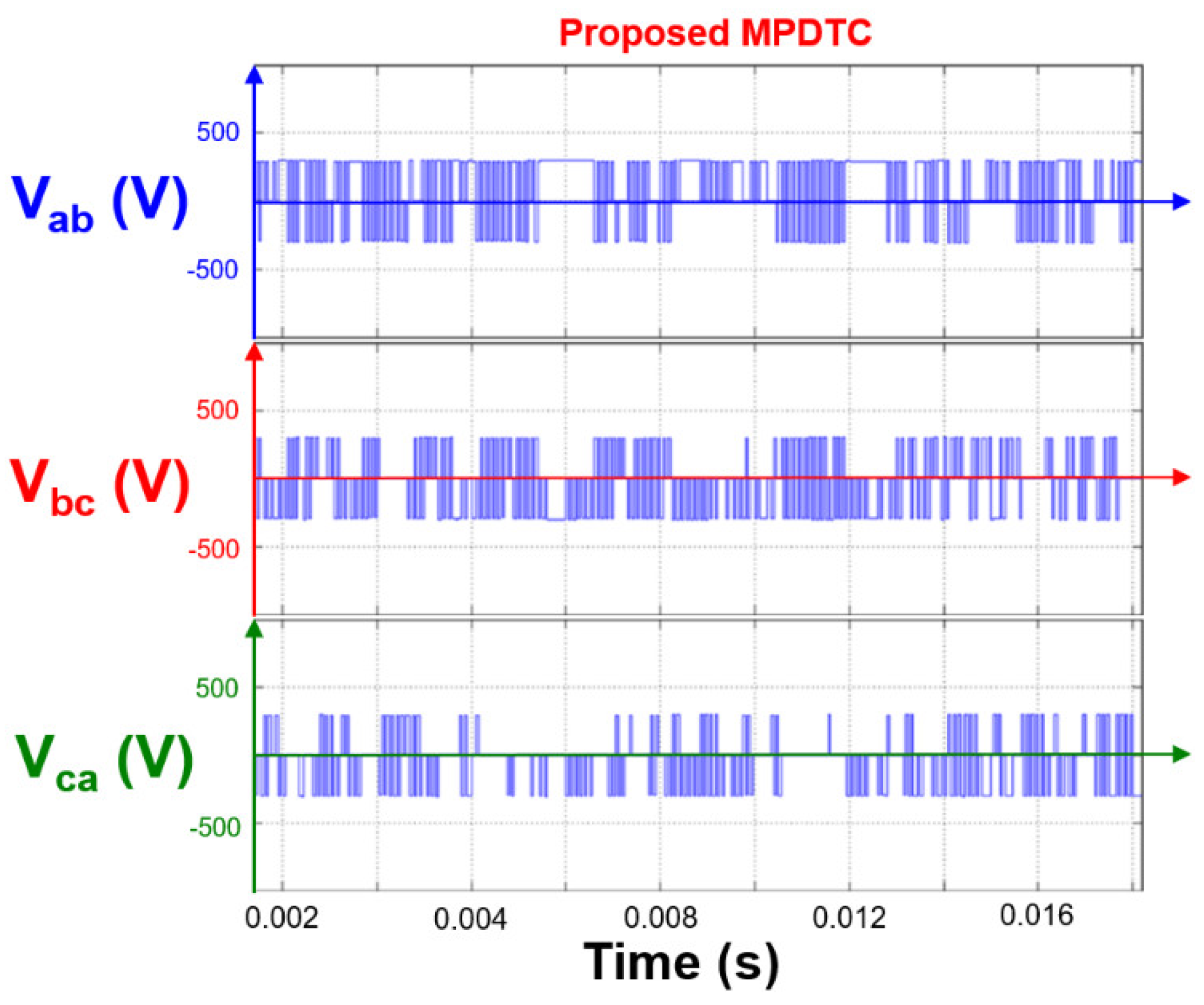
Figure 16.
Simulated line voltages in U–V-, V–W-, and W–U-phases (Vab, Vbc, and Vca, respectively) for a three-phase IM drive.
Figure 16.
Simulated line voltages in U–V-, V–W-, and W–U-phases (Vab, Vbc, and Vca, respectively) for a three-phase IM drive.
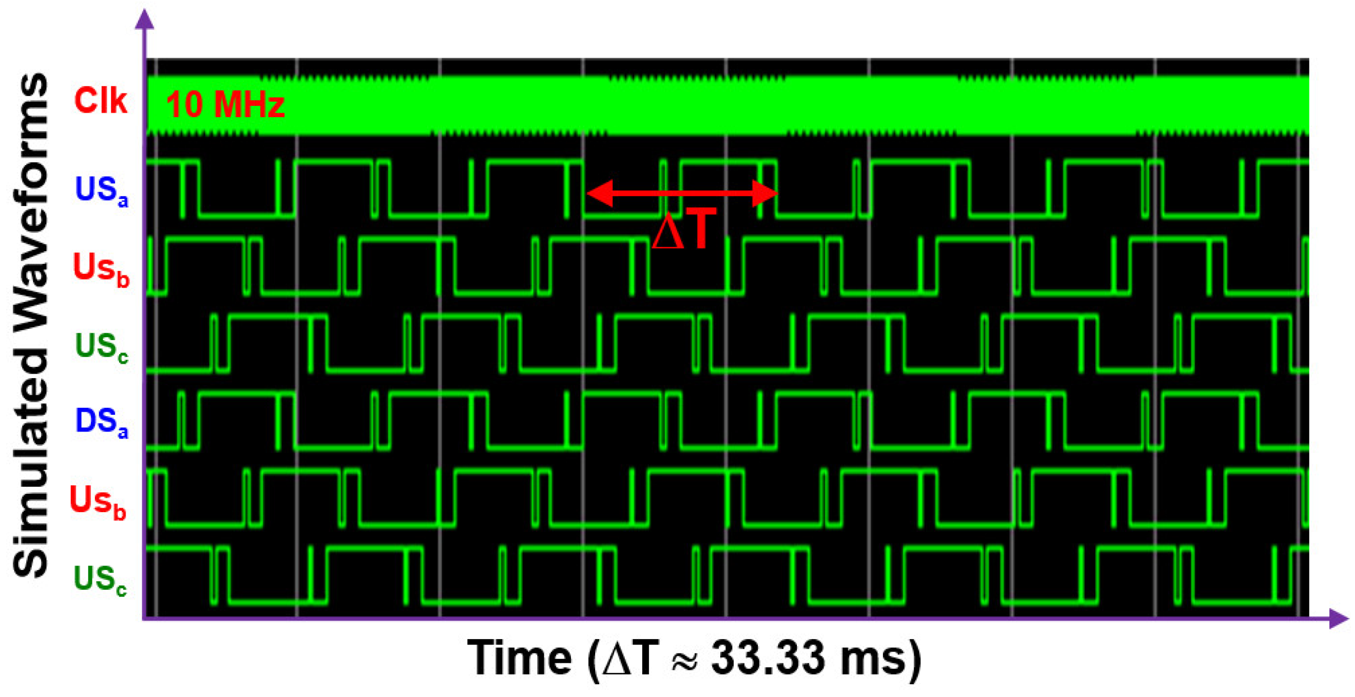
Figure 17.
Simulated voltage waveforms of six-arm signals in the inverter at a clock frequency of 10 MHz and a basic frequency of 1800 rpm (≈33.33 ms).
Figure 17.
Simulated voltage waveforms of six-arm signals in the inverter at a clock frequency of 10 MHz and a basic frequency of 1800 rpm (≈33.33 ms).
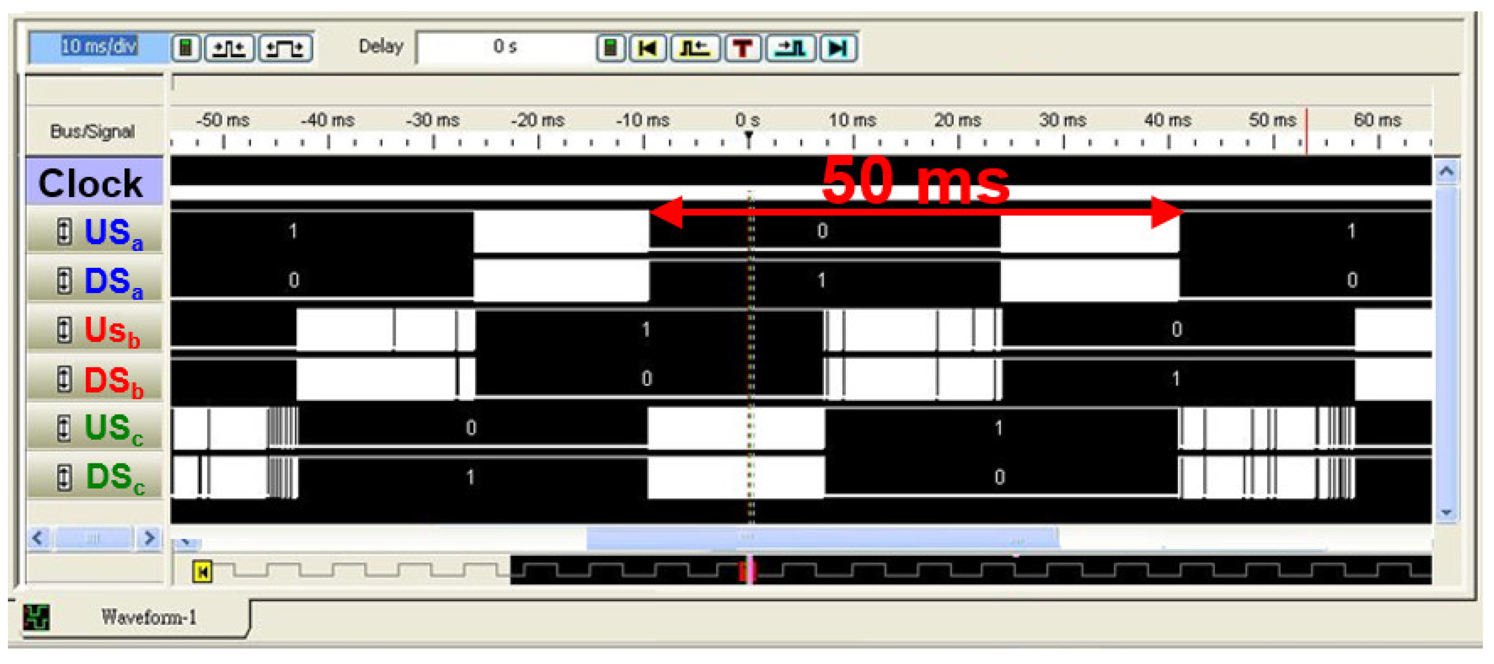
Figure 18.
Behavioral simulation of waveforms of six–arm voltage signals of the inverter at a clock frequency of 10 MHz and a basic frequency of 1800 rpm (≈50 ms).
Figure 18.
Behavioral simulation of waveforms of six–arm voltage signals of the inverter at a clock frequency of 10 MHz and a basic frequency of 1800 rpm (≈50 ms).
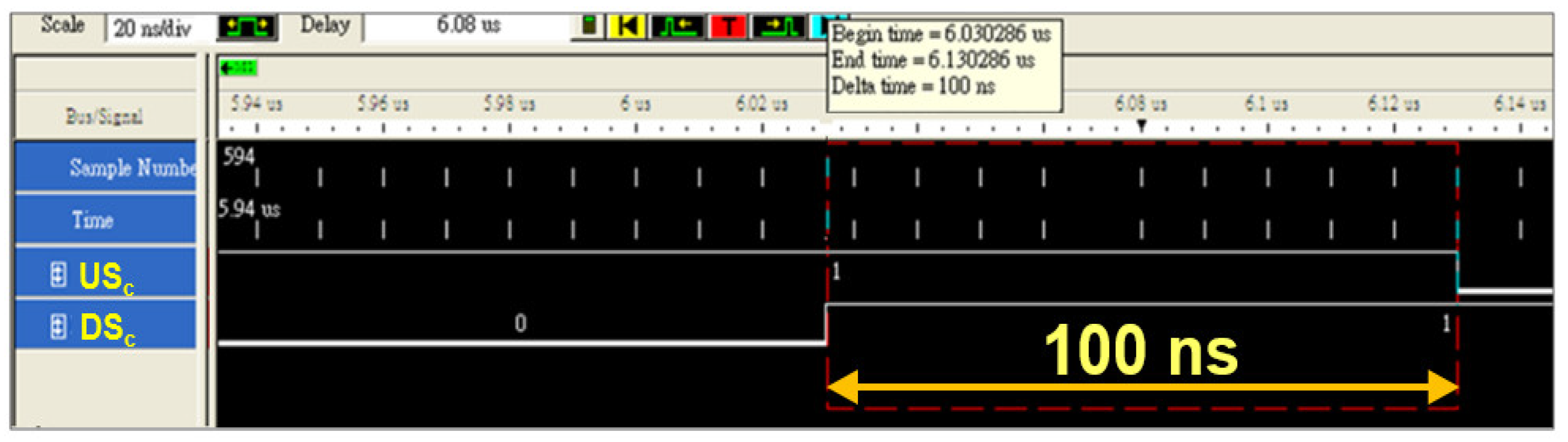
Figure 19.
Dead time of 100 ns measured in the W-phase by using the logic analyzer.
Figure 19.
Dead time of 100 ns measured in the W-phase by using the logic analyzer.
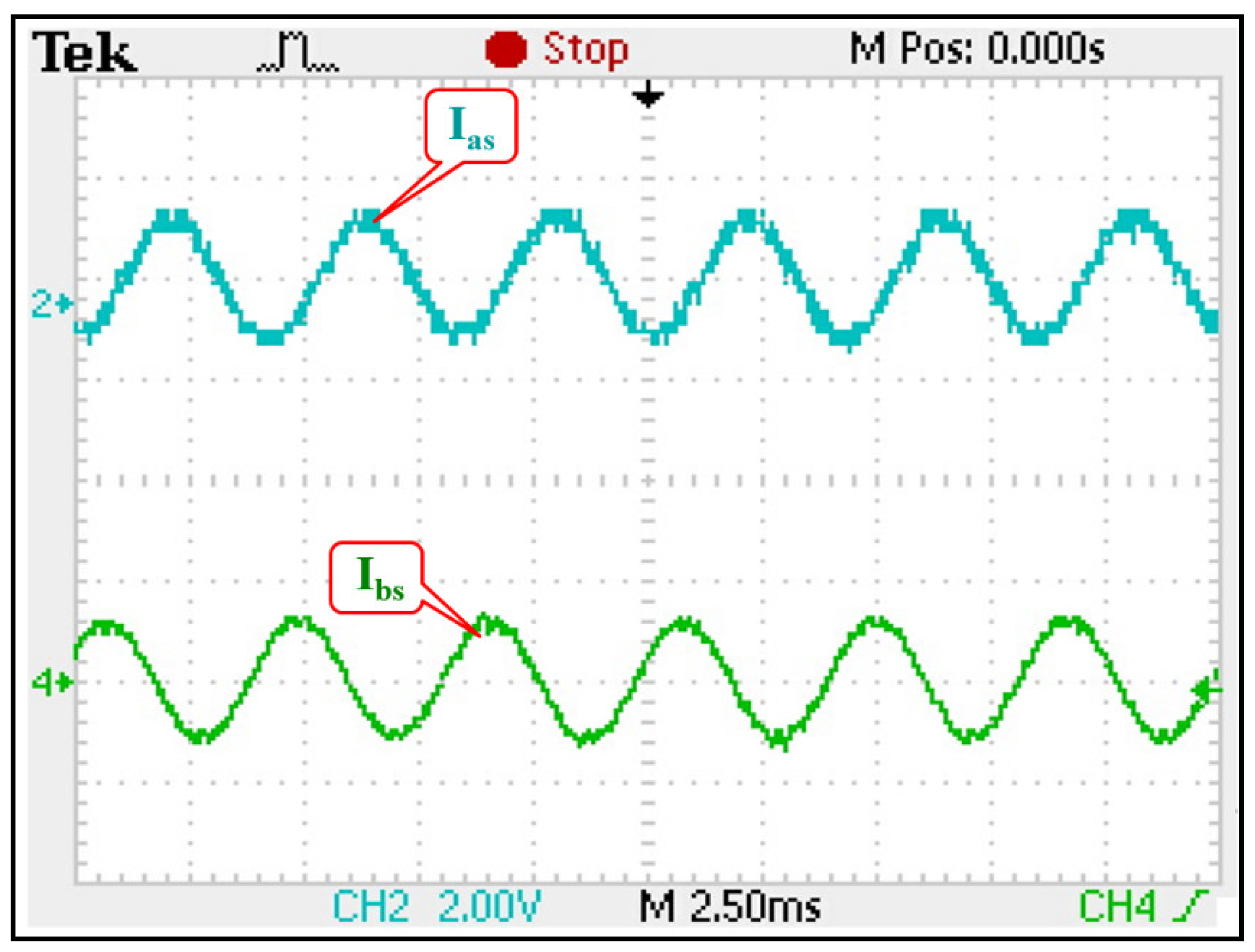
Figure 20.
Measured line currents Ias and Ibs at a sampling frequency of 100 kHz and a rotation frequency of 1200 rpm for a three–phase IM.
Figure 20.
Measured line currents Ias and Ibs at a sampling frequency of 100 kHz and a rotation frequency of 1200 rpm for a three–phase IM.
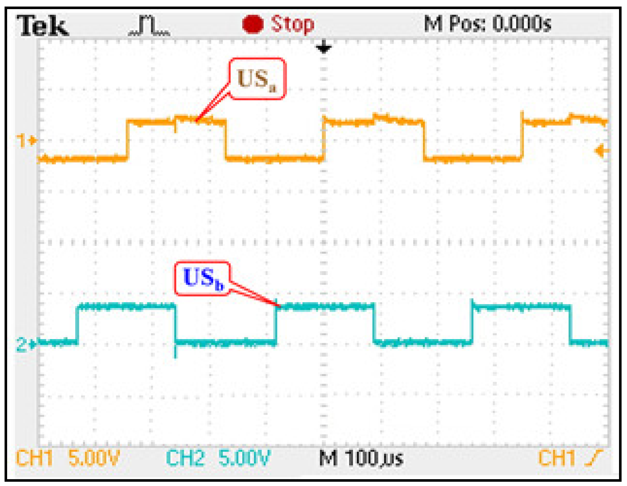
Figure 21.
Measured up–arm voltages in the U–phase and V–phase (USa and USb, respectively).
Figure 21.
Measured up–arm voltages in the U–phase and V–phase (USa and USb, respectively).
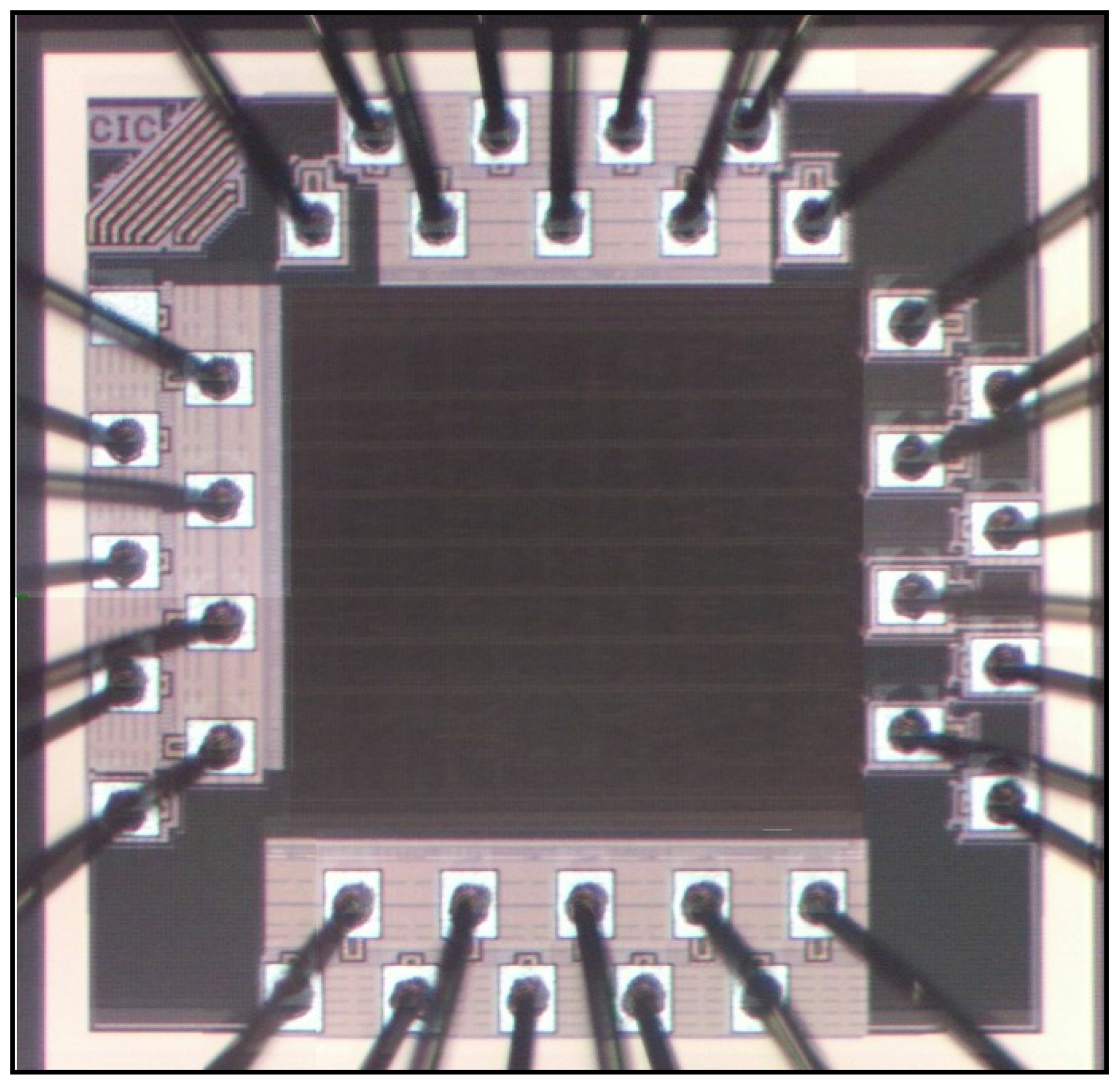
Figure 22.
Photomicrograph of the proposed MPDTC ASIC.
Figure 22.
Photomicrograph of the proposed MPDTC ASIC.
Table 1.
Sector selection of the proposed MPDTC ASIC.
Table 1.
Sector selection of the proposed MPDTC ASIC.
| λds | λqs | Output Sector |
|---|
| <0 | >0 | >0 | S1 |
| <0 | >0 | <0 | S1 |
| <0 | <0 | >0 | S4 |
| <0 | <0 | <0 | S4 |
| >0 | >0 | >0 | S2 |
| >0 | >0 | <0 | S6 |
| >0 | <0 | >0 | S3 |
| >0 | <0 | <0 | S5 |
Table 2.
Fuzzy rules of KP.
Table 2.
Fuzzy rules of KP.
| | Δe | PB | PS | ZE | NS | NB |
|---|
| e | |
|---|
| PB | PB | PB | PB | PB | PB |
| PS | PS | PB | PB | PB | PS |
| ZE | PS | PS | PB | PS | PS |
| NS | PS | PB | PB | PB | PS |
| NB | PB | PB | PB | PB | PB |
Table 3.
Fuzzy rules of Kd.
Table 3.
Fuzzy rules of Kd.
| | Δe | PB | PS | ZE | NS | NB |
|---|
| e | |
|---|
| PB | PS | PS | PS | PS | PS |
| PS | PB | PB | PS | PB | PB |
| ZE | PB | PB | PB | PB | PB |
| NS | PB | PB | PS | PB | PB |
| NB | PS | PS | PS | PS | PS |
Table 4.
Fuzzy rules of α.
Table 4.
Fuzzy rules of α.
| | e | PB | PS | ZE | NS | NB |
|---|
| Δe | |
|---|
| PB | 2 | 2 | 2 | 2 | 2 |
| PS | 4 | 3 | 2 | 3 | 4 |
| ZE | 5 | 4 | 3 | 4 | 5 |
| NS | 4 | 3 | 2 | 3 | 4 |
| NB | 2 | 2 | 2 | 2 | 2 |
Table 5.
Rules for the seven-stage fuzzy controller.
Table 5.
Rules for the seven-stage fuzzy controller.
| | et | PB | PM | PS | ZE | NS | NM | NB |
|---|
| Δet | |
|---|
| PB | NB | NB | NM | NM | NS | NS | ZE |
| PM | NB | NM | NM | NS | NS | ZE | PS |
| PS | NB | NM | NS | NS | ZE | PS | PM |
| ZE | NM | NS | NS | ZE | PS | PS | PM |
| NS | NM | NS | ZE | PS | PS | PM | PB |
| NM | NS | ZE | PS | PS | PM | PM | PB |
| NB | ZE | PS | PS | PM | PM | PB | PB |
Table 6.
Rules for the five-stage fuzzy controller.
Table 6.
Rules for the five-stage fuzzy controller.
| | et | PB | PS | ZE | NS | NB |
|---|
| Δet | |
|---|
| PB | NB | NS | NS | ZE | ZE |
| PS | NB | NS | NS | ZE | PS |
| ZE | NS | NS | ZE | PS | PS |
| NS | NS | ZE | PS | PS | PB |
| NB | ZE | ZE | PS | PS | PB |
Table 7.
MDMVV switching table.
Table 7.
MDMVV switching table.
| φ | τ | S1 | S2 | S3 | S4 | S5 | S6 |
|---|
| PB | PB | V2V2V2V2 | 3333 | 4444 | 5555 | 6666 | 1111 |
| PS | V2V2V2V6 | 3331 | 4442 | 5553 | 6664 | 1115 |
| ZE | V2V2V6V6 | 3311 | 4422 | 5533 | 6644 | 1155 |
| NS | V2V6V6V6 | 3111 | 4222 | 5333 | 6444 | 1555 |
| NB | V6V6V6V6 | 1111 | 2222 | 3333 | 4444 | 5555 |
| PM | PB | V2V2V2V2 | 3333 | 4444 | 5555 | 6666 | 1111 |
| PS | V2V2V2V7 | 3330 | 4447 | 5550 | 6667 | 1110 |
| ZE | V2V2V6V7 | 3310 | 4427 | 5530 | 6647 | 1150 |
| NS | V2V6V6V7 | 3110 | 4227 | 5330 | 6447 | 1550 |
| NB | V6V6V6V7 | 1110 | 2227 | 3330 | 4447 | 5550 |
| PS | PB | V2V2V2V3 | 3334 | 4445 | 5556 | 6661 | 1112 |
| PS | V2V2V2V5 | 3336 | 4441 | 5552 | 6663 | 1114 |
| ZE | V2V6V7V7 | 3300 | 4477 | 5500 | 6677 | 1100 |
| NS | V6V6V6V3 | 1114 | 2225 | 3336 | 4441 | 5552 |
| NB | V6V6V6V5 | 1116 | 2221 | 3332 | 4443 | 5554 |
| ZE | PB | V2V2V3V3 | 3344 | 4455 | 5566 | 6611 | 1122 |
| PS | V2V7V3V7 | 3040 | 4757 | 5060 | 6717 | 1020 |
| ZE | V2V3V5V6 | 3461 | 4512 | 5623 | 6134 | 1245 |
| NS | V2V7V5V0 | 3067 | 4710 | 5027 | 6730 | 1047 |
| NB | V6V5V0V0 | 1677 | 2100 | 3277 | 4300 | 5477 |
| NS | PB | V3V3V3V2 | 4443 | 5554 | 6665 | 1116 | 2221 |
| PS | V3V3V3V6 | 4441 | 5552 | 6663 | 1114 | 2225 |
| ZE | V3V3V0V0 | 4477 | 5500 | 6677 | 1100 | 2277 |
| NS | V5V5V5V2 | 6663 | 1114 | 2225 | 3336 | 4441 |
| NB | V5V5V5V6 | 6661 | 1112 | 2223 | 3334 | 4445 |
| NM | PB | V3V3V3V0 | 4447 | 5550 | 6667 | 1110 | 2227 |
| PS | V5V3V3V0 | 6447 | 1550 | 2667 | 3110 | 4227 |
| ZE | V5V5V3V0 | 6647 | 1150 | 2267 | 3310 | 4427 |
| NS | V5V5V5V0 | 6667 | 1110 | 2227 | 3330 | 4447 |
| NB | V5V5V5V5 | 6666 | 1111 | 2222 | 3333 | 4444 |
| NB | PB | V3V3V3V3 | 4444 | 5555 | 6666 | 1111 | 2222 |
| PS | V3V3V3V5 | 4446 | 5551 | 6662 | 1113 | 2224 |
| ZE | V3V3V5V5 | 4466 | 5511 | 6622 | 1133 | 2244 |
| NS | V5V5V5V3 | 6664 | 1115 | 2226 | 3331 | 4442 |
| NB | V5V5V5V5 | 6666 | 1111 | 2222 | 3333 | 4444 |
Table 8.
Rules for the five-state fuzzy controller.
Table 8.
Rules for the five-state fuzzy controller.
| Example | (1) | (2) | (3) | (4) |
|---|
| Time | T1,T2,T3,T4 | T1,T2,T3,T4 | T1,T2,T3,T4 | T1,T2,T3,T4 |
| Vector | V2,V2,V2,V2 | V2,V7,V5,V0 | V2,V3,V5,V6 | V5,V5,V5,V5 |
| Torque | ↑↑↑↑ (+4) | ↑↓↓↓ (−2) | ↑↑↓↓ (+0) | ↓↓↓↓ (−4) |
| Flux | ↑↑↑↑ (+4) | ↑-↓- (+0) | ↑↓↓↑ (+0) | ↓↓↓↓ (−4) |
Table 9.
System specifications of proposed MPDTC ASIC.
Table 9.
System specifications of proposed MPDTC ASIC.
| Items | Specifications |
|---|
| Technology | 0.18-μm 1P6M CMOS |
| Supplied Voltage | 1.8 V |
| Test Coverage | 95.64% |
| Fault Coverage | 93.28% |
| Operating Frequency | 10 MHz |
| Sampling rate | 100 kS/s |
| Power Consumption | 2.457 mW |
| Gate Counts | 99,188 |
| Chip Size | 1.193 mm × 1.190 mm |
| Pins | 35 |


