
A Compact CSRR-Based Sensor for Characterization of the Complex Permittivity of Dielectric Materials

 , , , and
Abstract
:1. Introduction
2. Materials and Methods
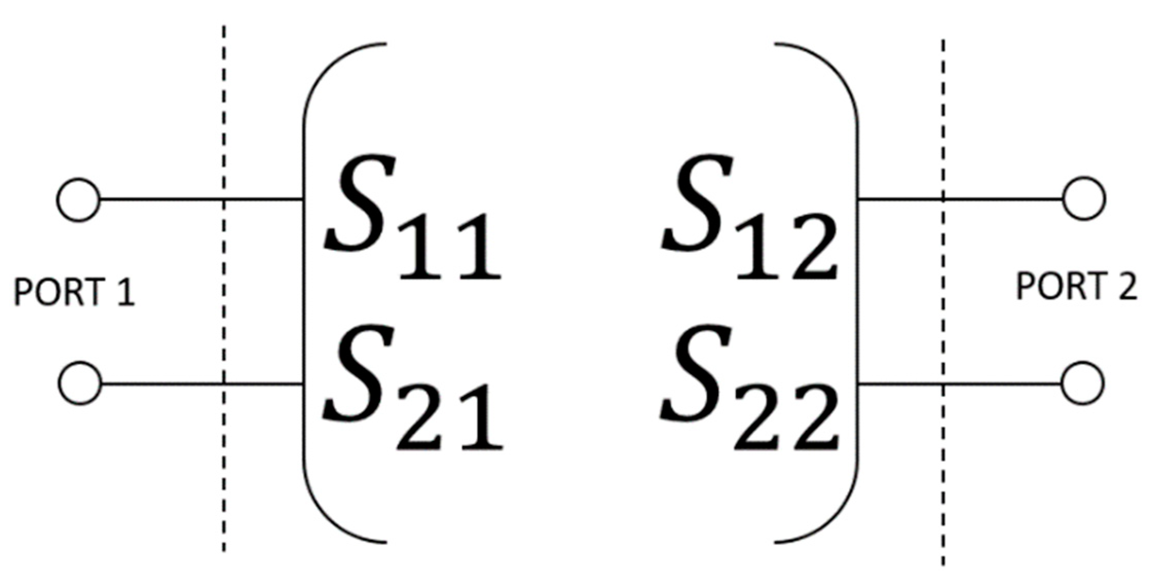
2.1. Theory and Principle of Operation
2.2. Sensitivity Analysis
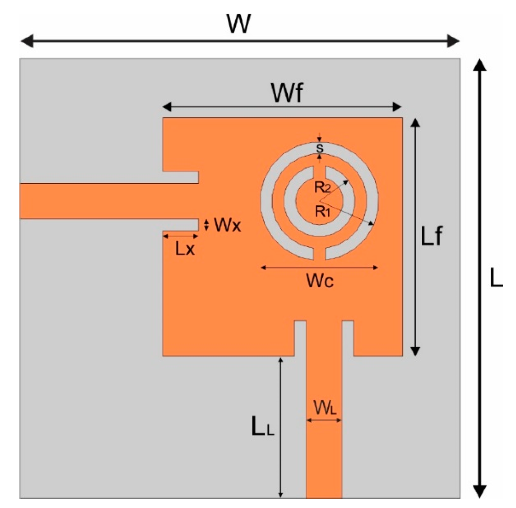
2.3. Design and Modeling of Sensor
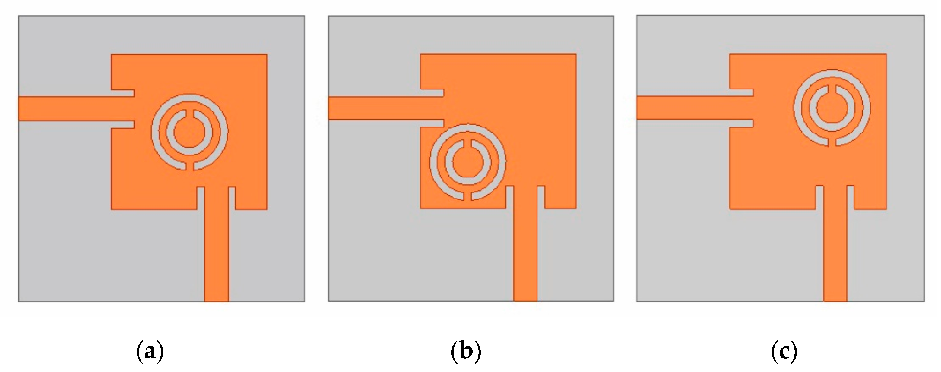
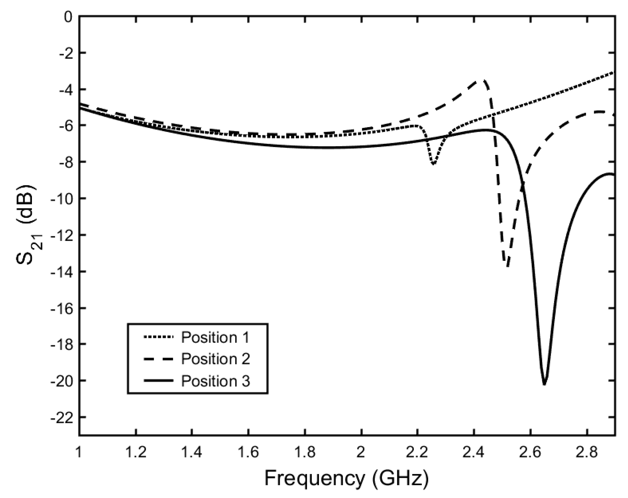
Positioning of CSRR
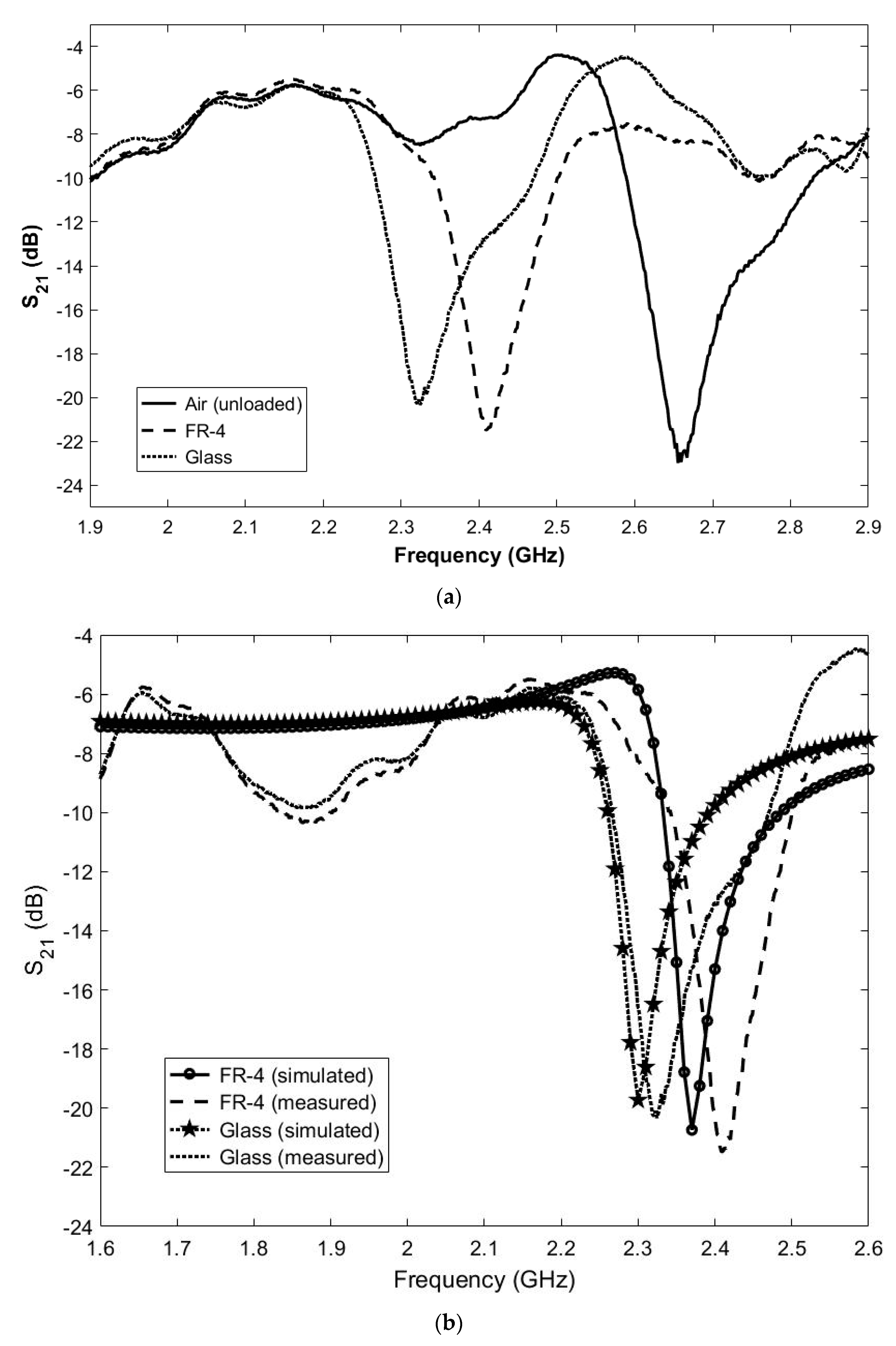
3. Results and Discussion
4. Conclusions
Author Contributions
Funding
Acknowledgments
Conflicts of Interest
References
- Jilani, M.T.; Wen, W.P.; Cheong, L.Y.; Rehman, M.Z.U. A Microwave ring-resonator sensor for non-invasive assessment of meat aging. Sensors 2016, 16, 52. [Google Scholar] [CrossRef]
- Trabelsi, S.; Nelson, S.O. Microwave sensing of quality attributes of agricultural and food products. IEEE Instrum. Meas. Mag. 2016, 19, 36–41. [Google Scholar] [CrossRef]
- Li, Q.L.; Cheung, S.W.; Wu, D.; Yuk, T.I. Optically transparent dual-band MIMO antenna using micro-metal mesh conductive film for WLAN system. IEEE Ant. Wirel. Propag. Lett. 2016, 16, 920–923. [Google Scholar] [CrossRef]
- Kumari, R.; Patel, P.N.; Yadav, R. An ENG-inspired microwave sensor and functional technique for label-free detection of aspergillus niger. IEEE Sens. J. 2018, 18, 3932–3939. [Google Scholar] [CrossRef]
- Wei, Z.; Huang, J.; Li, J.; Xu, G.; Ju, Z.; Liu, X.; Ni, X. A High-sensitivity microfluidic sensor based on a substrate integrated waveguide re-entrant cavity for complex permittivity measurement of liquids. Sensors 2018, 18, 4005. [Google Scholar] [CrossRef] [PubMed] [Green Version]
- Chretiennot, T.; Dubuc, D.; Grenier, K. A microwave and microfluidic planar resonator for efficient and accurate complex permittivity characterization of aqueous solutions. IEEE Trans. Microw. Theory Tech. 2012, 61, 972–978. [Google Scholar] [CrossRef] [Green Version]
- Ebrahimi, A.; Scott, J.; Ghorbani, K. Ultrahigh-Sensitivity Microwave Sensor for Microfluidic Complex Permittivity Measurement. IEEE Trans. Microw. Theory Tech. 2019, 67, 4269–4277. [Google Scholar] [CrossRef]
- Nitsche, R.G.; Preissner, J.; Biebl, E.M. A free space technique for measuring the complex permittivity and permeability in the millimeter wave range. In Proceedings of the 1994 IEEE MTT-S International Microwave Symposium Digest, San Diego, CA, USA, 23–27 May 1994; pp. 1465–1468. [Google Scholar]
- Wu, J.; Wang, P.; Huang, X.J.; Rao, X.F.; Chen, X.; Shen, Z.; Yang, H. Design and validation of liquid permittivity sensor based on RCRR microstrip metamaterial. Sens. Actuators A Phys. 2018, 280, 222–227. [Google Scholar] [CrossRef]
- Boybay, M.S.; Ramahi, O.M. Material characterization using complementary split-ring resonators. IEEE Trans. Instrum. Meas. 2012, 61, 3039–3046. [Google Scholar] [CrossRef]
- Oliveira, J.G.D.; Pinto, E.N.M.G.; Silva Neto, V.P.; D’Assunção, A.G. CSRR-based microwave sensor for dielectric materials characterization applied to soil water content determination. Sensors 2020, 20, 255. [Google Scholar] [CrossRef] [Green Version]
- Ebrahimi, A.; Withayachumnankul, W.; Al-Sarawi, S.; Abbott, D. High-sensitivity metamaterial-inspired sensor for microfluidic dielectric characterization. IEEE Sens. J. 2013, 14, 1345–1351. [Google Scholar] [CrossRef] [Green Version]
- Tiwari, N.K.; Singh, S.P.; Akhtar, M.J. Novel Improved sensitivity planar microwave probe for adulteration detection in edible oils. IEEE Microw. Wirel. Comp. Lett. 2019, 29, 164–166. [Google Scholar] [CrossRef]
- Ansari, M.A.H.; Jha, A.K.; Akhtar, M.J. Design and application of the CSRR-based planar sensor for noninvasive measurement of complex permittivity. IEEE Sens. J. 2015, 15, 7181–7189. [Google Scholar] [CrossRef]
- Saadat-Safa, M.; Nayyeri, V.; Khanjarian, M.; Soleimani, M.; Ramahi, O.M. A CSRR-based sensor for full characterization of magneto-dielectric materials. IEEE Trans. Microw. Theory Tech. 2019, 67, 806–814. [Google Scholar] [CrossRef]
- Fan, L.; Zhao, W.; Gan, H.; He, L.; Liu, Q.; Dong, L.; Wang, G. A high-Q active substrate integrated waveguide based sensor for fully characterizing magneto-dielectric (MD) materials. Sens. Actuators A Phys. 2020, 301, 111778. [Google Scholar] [CrossRef]
- Zhao, W.; Gan, H.; He, L.; Liu, Q.; Wang, D.; Xu, K.; Chen, S.; Dong, L.; Wang, G. Microwave planar sensors for fully characterizing magneto-dielectric materials. IEEE Access 2020, 8, 41985–41999. [Google Scholar] [CrossRef]
- Ebrahimi, A.; Scott, J.; Ghorbani, K. Differential Sensors Using Microstrip Lines Loaded with Two Split-Ring Resonators. IEEE Sens. J. 2018, 18, 5786–5793. [Google Scholar] [CrossRef]
- Kapoor, A.; Varshney, P.K.; Akhtar, M.J. Interdigital capacitor loaded electric-LC resonator for dielectric characterization. Microw. Opt. Technol. Lett 2020, 62, 1–6. [Google Scholar] [CrossRef]
- Ali, L.; Wang, C.; Ullah, I.; Yousaf, A.; Khan, W.U.; Ullah, S.; Khan, R.; Alassery, F.; Hamam, H.; Shafiq, M. Design and Optimization of Microwave Sensor for the Non-Contact Measurement of Pure Dielectric Materials. Electronics 2021, 10, 3057. [Google Scholar] [CrossRef]
- Chen, S.; Guo, M.; Xu, K.; Zhao, P.; Dong, L.; Wang, G. A Frequency synthesizer based microwave permittivity sensor using CMRC structure. IEEE Access 2018, 6, 8556–8563. [Google Scholar] [CrossRef]
- Ebrahimi, A.; Scott, J.; Ghorbani, K. Transmission Lines Terminated with LC Resonators for Differential Permittivity Sensing. IEEE Microw. Wirel. Comp. Lett. 2018, 28, 1149–1151. [Google Scholar] [CrossRef]
- Yeo, J.; Lee, J.-I. Meander-line slot-loaded high-sensitivity microstrip patch sensor antenna for relative permittivity measurement. Sensors 2019, 19, 4660. [Google Scholar] [CrossRef] [PubMed] [Green Version]
- Vélez, P.; Muñoz-Enano, J.; Ebrahimi, A.; Herrojo, C.; Paredes, F.; Scott, J. Single-Frequency Amplitude-Modulation Sensor for Dielectric Characterization of Solids and Microfluidics. IEEE Sens. J. 2021, 21, 12189–12201. [Google Scholar] [CrossRef]
- 3GPP TS 36.101. Evolved Universal Terrestrial Radio Access (E-UTRA). In User Equipment (UE) Radio Transmission and Reception (Release 15); ETSI: Sophia Antipolis, France, 2019. [Google Scholar]


| Parameter | Value (mm) | Parameter | Value (mm) |
|---|---|---|---|
| W | 37 | Wc | 10 |
| L | 37 | Wx | 1 |
| Wf | 20 | Lx | 3 |
| Lf | 20 | R1 | 5 |
| WL | 3 | R2 | 3 |
| LL | 12 | s | 1 |
| MUT | Simulated Resonance Frequency (GHz) | Measured Resonance Frequency (GHz) | Difference (%) |
|---|---|---|---|
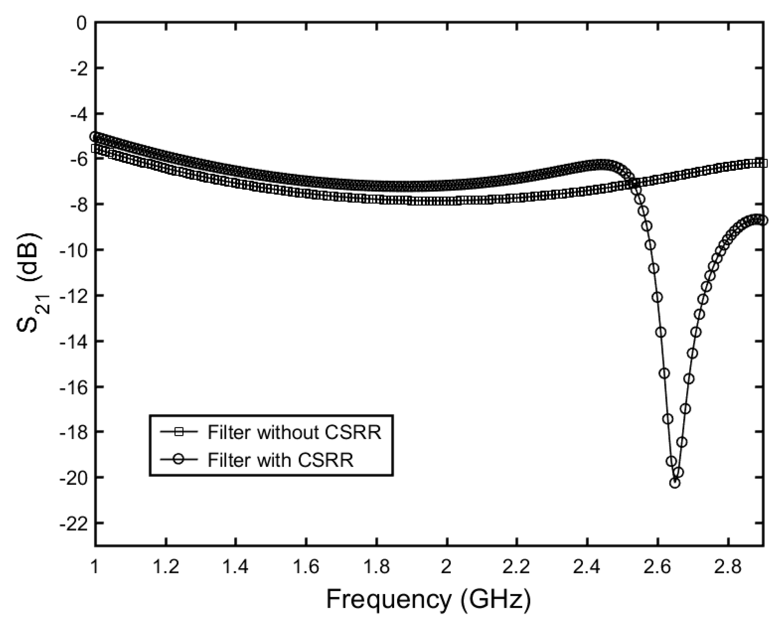
| Air | 2.65 | 2.645 | 0.19 |
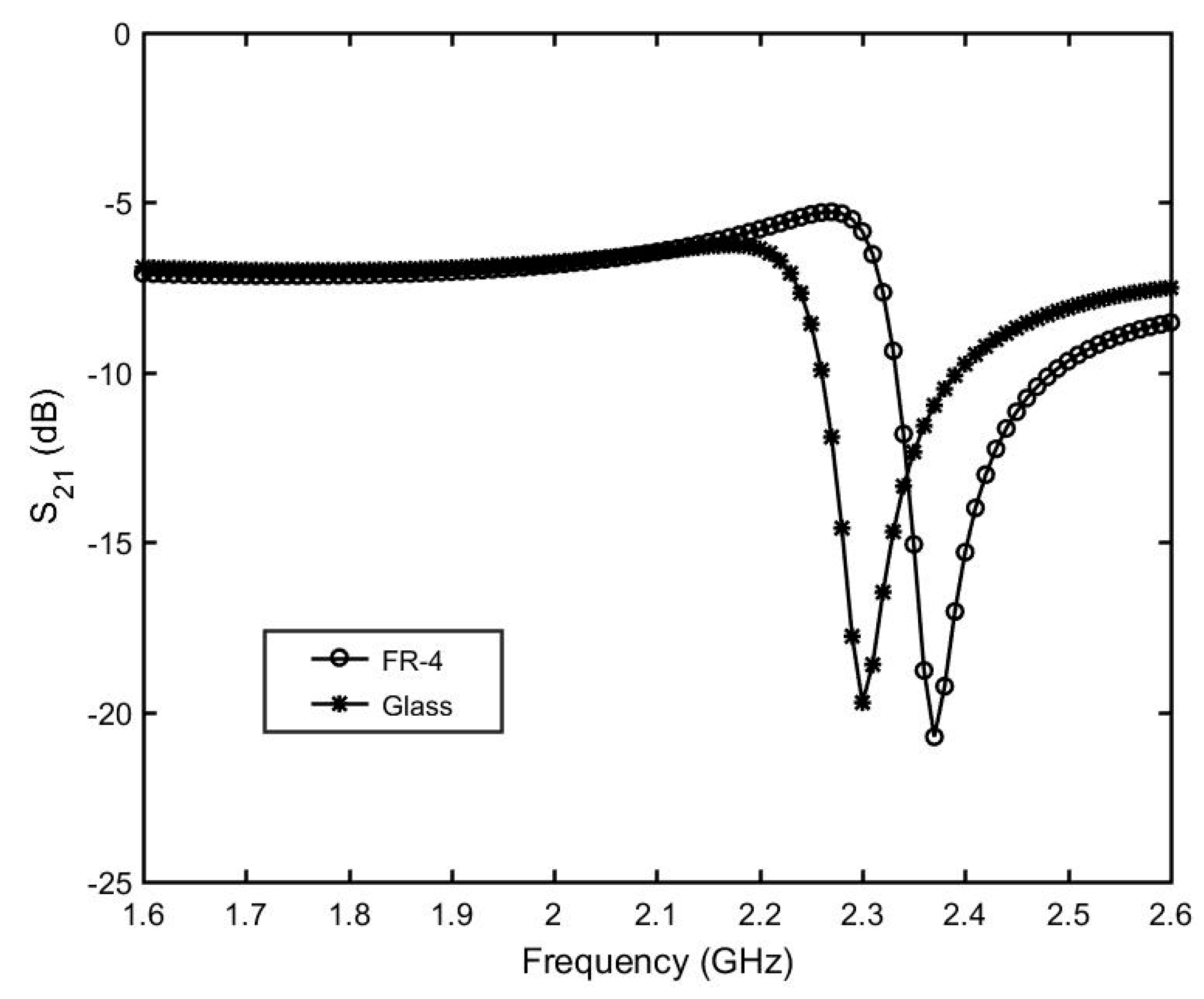
| FR-4 | 2.37 | 2.4 | 1.25 |
| Glass | 2.30 | 2.31 | 0.43 |
| MUT | Difference (%) | |||||
|---|---|---|---|---|---|---|
| This Work | Literature | This Work | Literature | |||
| FR-4 | 4.25 | 4.3–4.4 [10,11,15] | 0.0198 | 0.02 [10,11,15] | 1.18 | 1.01 |
| Glass | 5.37 | 5.5 [3,11] | 0.0296 | 0.03 [8] | 2.42 | 1.35 |
| Ref. | Reson. Type | Meas. Reson. Freq. (GHz) | Size (mm × mm) | Sens. Param. | S (MHz) | Complex Permitt. | Max. Error (%) | |
|---|---|---|---|---|---|---|---|---|
| [5] | SIW cavity reson. | 2.188 | 55 × 50 | S21 | 8.1 | 0.368 | Yes | 3.24 |
| [14] | CSRR | 2.65 | 40 × 26 | S21 | 105.5 | 3.98 | Yes | 3.84 |
| [15] | CSRR | 2.461 | N/A | S21 | 42.2 | 1.71 | Yes | 1.56 |
| [18] | SRR | 2.41 | N/A | S21 | 72 | 3.63 | No | 3.6 |
| [19] | IDC | 3.316 | 40 × 50 | S21 | 166 | 5.05 | No | 14.01 |
| [23] | Meander-line slot | 2.5 | 80 × 80 | S11 | 102 | 4.06 | No | 2.68 |
| This Work | CSRR | 2.65 | 37 × 37 | S21 | 128 | 4.82 | Yes | 2.42 |
Publisher’s Note: MDPI stays neutral with regard to jurisdictional claims in published maps and institutional affiliations. |
© 2022 by the authors. Licensee MDPI, Basel, Switzerland. This article is an open access article distributed under the terms and conditions of the Creative Commons Attribution (CC BY) license (https://creativecommons.org/licenses/by/4.0/).
Share and Cite
Nogueira, J.K.A.; Oliveira, J.G.D.; Paiva, S.B.; Neto, V.P.S.; D’Assunção, A.G. A Compact CSRR-Based Sensor for Characterization of the Complex Permittivity of Dielectric Materials. Electronics 2022, 11, 1787. https://doi.org/10.3390/electronics11111787
Nogueira JKA, Oliveira JGD, Paiva SB, Neto VPS, D’Assunção AG. A Compact CSRR-Based Sensor for Characterization of the Complex Permittivity of Dielectric Materials. Electronics. 2022; 11(11):1787. https://doi.org/10.3390/electronics11111787
Chicago/Turabian StyleNogueira, Jurgen K. A., João G. D. Oliveira, Samuel B. Paiva, Valdemir P. Silva Neto, and Adaildo G. D’Assunção. 2022. "A Compact CSRR-Based Sensor for Characterization of the Complex Permittivity of Dielectric Materials" Electronics 11, no. 11: 1787. https://doi.org/10.3390/electronics11111787