Article

Dual-Band Circularly Polarized Hybrid Dielectric Resonator Antenna for 5G Millimeter-Wave Applications

School of Science, Wuhan University of Technology, Wuhan 430070, China
*
Author to whom correspondence should be addressed.
Electronics 2022, 11(11), 1761; https://doi.org/10.3390/electronics11111761
Submission received: 11 May 2022 / Revised: 27 May 2022 / Accepted: 30 May 2022 / Published: 1 June 2022
(This article belongs to the Special Issue Metasurfaces Applications in Antennas and Microwave Devices)

Abstract

:
This paper proposes a dual-band circularly polarized (CP) rectangular dielectric resonator antenna (DRA) for 5G millimeter wave wireless communications. The proposed DRA consists of a novel modified cross-flower exciting (MCF) slot and a rectangular ceramic dielectric resonator (DR). With the help of the compact MCF feeding slot, the fundamental modes TE δ 11 x / TE 1 δ 1 y and higher-order modes TE δ 13 x / TE 1 δ 3 y of the DR can be excited to achieve CP dual-band characteristics. In addition, the MCF slot works as a radiator at 26 GHz and 39 GHz to enhance the DRA bandwidth. More importantly, these two operational bandwidths can be controlled independently at the lower and upper bands. The proposed DRA is designed, fabricated and measured. The measured results show that the proposed dual-band CP DRA achieves 3 dB axial-ratio (AR) bandwidths of 19.8% and 7.8% with peak gains of 5.62 dBic and 6.74 dBic for the lower and upper bands.

1. Introduction

With the advantages of higher data transfer rates, higher resolution and lower latency, millimeter-wave (mm-wave) wireless communication has caused much attention in the 5th Generation (5G) of communication and beyond [1]. Different frequency bands have been released for 5G communications, such as 24.25–27.5 GHz and 37–42.5 GHz in China [2]. Several mm-wave antennas have been proposed for 5G applications [3,4]. Due to a considerable ohmic loss and surface wave at the mm-wave frequency, the antenna efficiency is degraded. In contrast, dielectric resonator (DR) antennas (DRAs) could avoid the ohmic loss and surface waves to maintain high radiation efficiency at mm-wave bands [5,6]. In addition, with various dielectric constants and resonant modes, the DRA features a high degree of design freedom. For these attractive advantages, DRAs have great potential for mm-wave applications.
Currently, plenty of DRAs provide improved performance for mm-wave applications; for example, DRAs have been investigated for high gain performance [7,8,9], low-profile performance [10], and wideband/dual-band performance [11,12,13,14]. However, most of them are focused on linearly polarized (LP) antennas [8,9,10,11,12,13,14]. As we know, circularly polarized (CP) antennas can avoid the polarization mismatch and can minimize the multipath fading [15,16], which is more appropriate for wireless communications. Therefore, it is necessary to design CP DRAs to meet the requirements for high-quality communications. In addition, for 5G mm-wave applications, DRAs with multiband/wideband characteristics have received much attention. Some wideband or dual-band CP DRAs have been realized with the help of feeding slots to generate various exciting modes [17,18,19,20]. For example, an embedded substrate-integrated DRA (SIDRA) fed by a cross-slot was proposed in [19], which could achieve a CP bandwidth of about 26.3% at 26 GHz. Compared to wideband DRAs, dual-band ones show unique advantages in confining undesired signals between lower and upper bands and providing more communication channels. For instance, in [20], a layered chamfered rectangular DRA fed by an asymmetrical cross-slot was demonstrated to achieve dual-band CP radiation with bandwidths of 12.8% at 22 GHz and 5% at 28 GHz. However, the modified shapes of DR increase the fabrication complexity, especially at the micron scale. In addition, since different frequency bands have been released for 5G communications, each operational frequency of the dual-band DRA design is desired for easy control. In [20], the fundamental and higher-order modes are generated by a single feeding slot, and dual-bandwidth is challenging to control independently, which increases the design complexity. Thus, our work aims to investigate an mm-wave CP dual-band DRA with a traditional shape, where each operational bandwidth of the dual-band DRA can be independently controlled by a multi-slot feeding structure.
This work proposes a wide dual-band CP rectangular DRA at the mm-wave bands for 5G NR communications. The DRA consists of a novel modified cross-flower (MCF) exciting slot and a rectangular DR. The MCF slot contains three independent slot structures, which can independently control the lower and upper band. Moreover, two couples of orthogonal resonant modes are comprehensively excited by the MCF slot, and the hybrid MCF slot is proposed to increase the bandwidth of the DRA. A prototype of the proposed DRA has been designed, fabricated and measured. It was found that measured 3 dB axial-ratio (AR) bandwidths of 19.8% and 7.8% can be achieved for the lower and upper bands. Broadside radiation patterns were obtained across all of the 3 dB AR bandwidths. Moreover, the details of the design and analysis are presented and discussed in the following section.

2. Antenna Design

This section demonstrates the details of the antenna configuration and the design evolution of the proposed dual-band CP DRA.

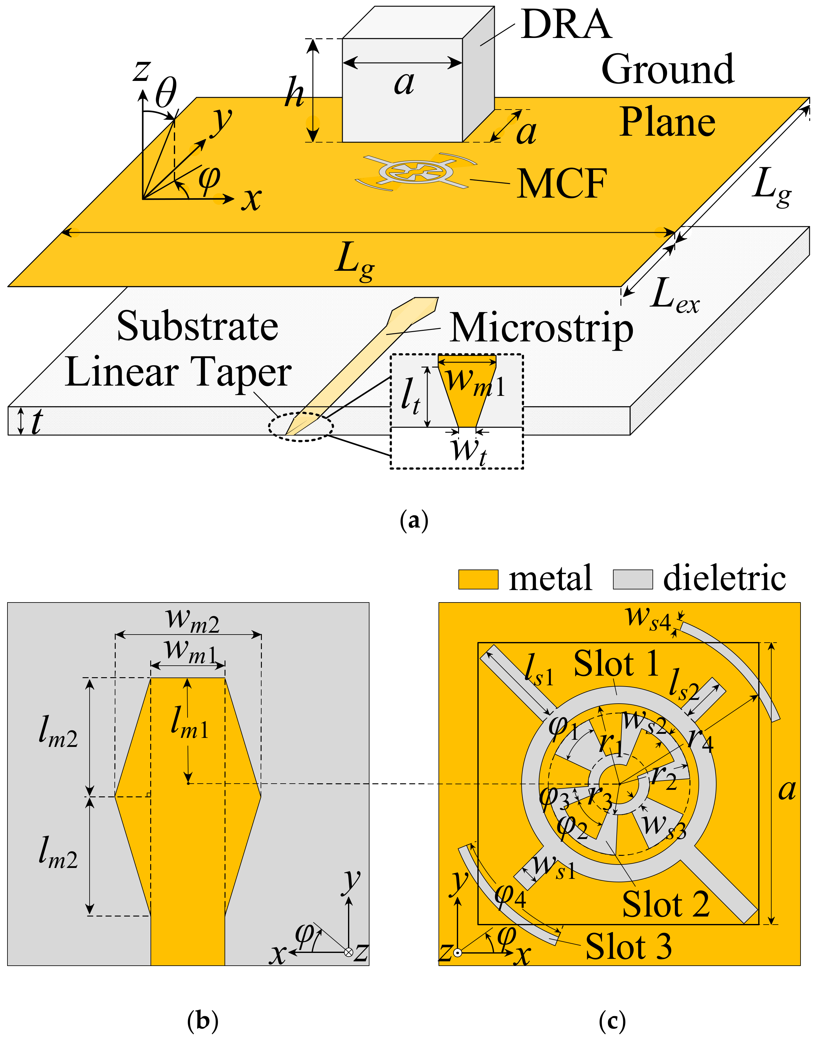
2.1. Antenna Configuration

The entire geometry of the proposed dual-band CP RDRA is shown in Figure 1a. The DR (εr = 7 and tan δ = 0.005), made of magnesium metasilicate ceramics, is mounted on a Rogers 5880 (εr = 2.2 and tan δ = 0.0009) substrate. A microstrip-fed modified cross-flower (MCF) slot is etched on the conductive ground plane and underneath the DR. The ground plane is extended Lex along −y directions for mounting an end launch connector. The end launch connector is used to excite the antenna and connect the antenna to the measuring system. Note that the end launch connector is used in this proposed design because of its better performance and ease of installation and removal at the Ka-band [21] and U-band [11]. As shown in Figure 1b, the end of the microstrip line is modified to a hexagonal shape for better impedance matching. Figure 1c is the layout of the MCF exciting slot, which consists of a modified cross-slot (Slot 1), a cross-flower slot (Slot 2) and a pair of equal arc-shaped slots (Slot 3). All the parameters are optimized using CST Microwave Studio considering the end launch connector model, and the detailed dimensions of the proposed DRA are listed in Table 1.

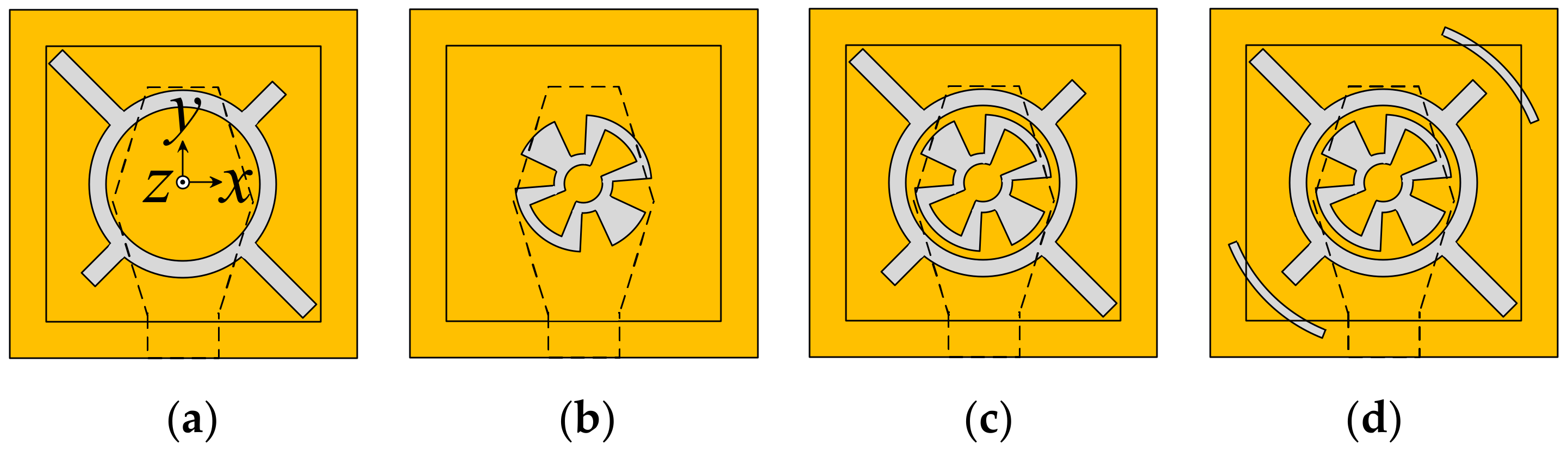
2.2. Evolution of the Design

Four antennas (Antenna 1, 2, 3 and 4) are illustrated in Figure 2 to show the evolution of the design. The simulated results of reflection coefficient (|S11|) and axial-ratio (AR) for these DRAs are plotted in Figure 3a,b, respectively. Antenna 1 is proposed as the starting point of the design due to its wide bandwidth and CP characteristics [22]. From the results, Antenna 1 obtains the impedance bandwidth (|S11| < −10 dB) of 23.8–33.2 GHz and 3 dB AR bandwidth of 24.6–30.6 GHz. Since Slot 2 can excite a pair of higher resonant modes ( TE δ 13 x and TE 1 δ 3 y ) in the DR, Slot 2 is added in Antenna 1 (seen as Antenna 3) to get dual-band CP characteristics. Antenna 3 roughly achieves the goal of dual-band CP characteristics, but the AR is higher than 3 dB at 38.5 GHz. To reduce the AR at 38.5 GHz, a pair of equal arc-shaped slots are used in Antenna 4 (the proposed antenna). Compared with Antenna 3, the AR of Antenna 4 is reduced from 4.5 dB to 2.8 dB at 38.5 GHz, while the impedance bandwidths remain almost unchanged. The simulated results show that Antenna 4 obtains the impedance bandwidths of 23.3% (23.9–30.2 GHz) and 25% (35.3–45.4 GHz), and AR bandwidths of 15.1% (24.5–28.5 GHz) and 16.1% (36–42.3 GHz), respectively. As shown in Figure 3, the impedance bandwidths of Antenna 4 are wider than the AR bandwidths at the lower and upper bands. It is because the impedance bandwidths cover overall frequency bands generated by all excited modes, while at some frequencies, the E-fields do not satisfy the CP radiation condition.

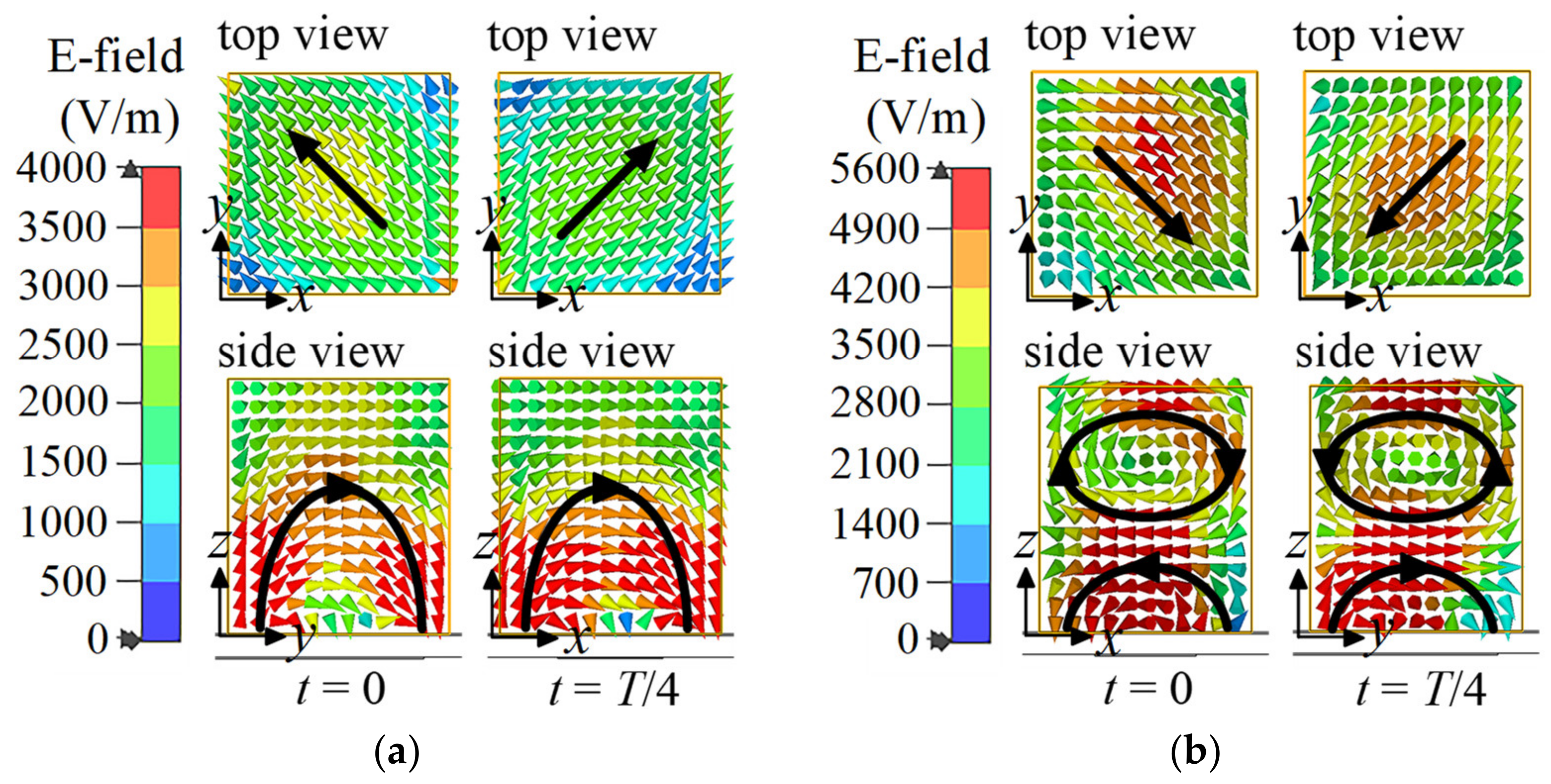
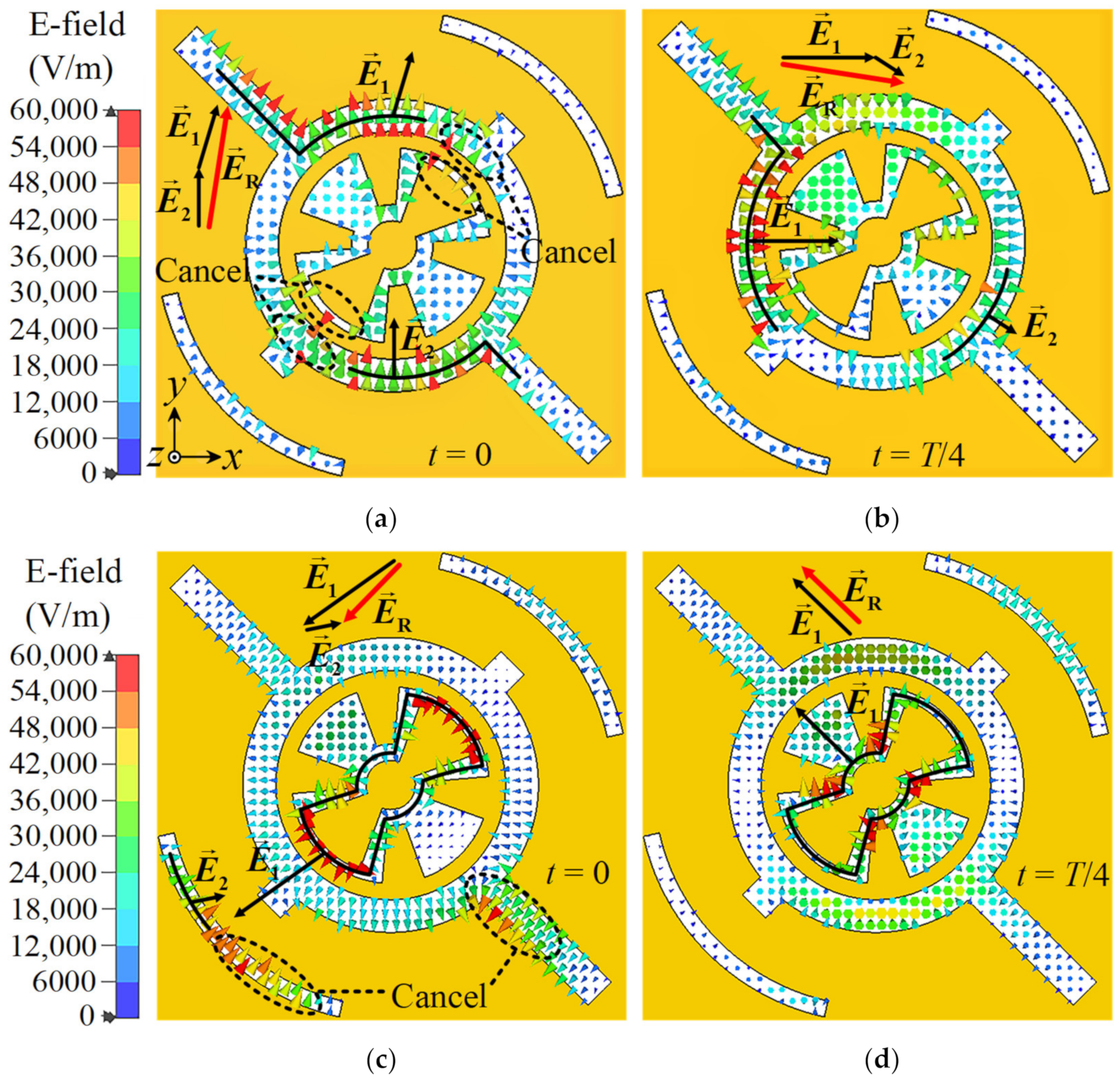
3. Working Mechanism
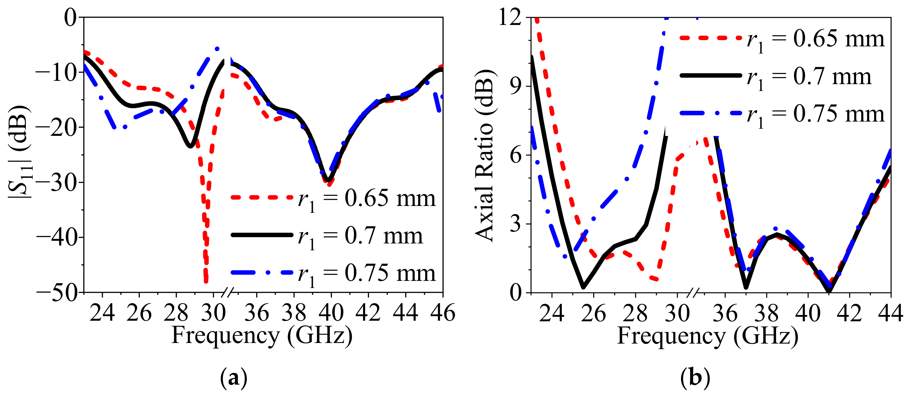
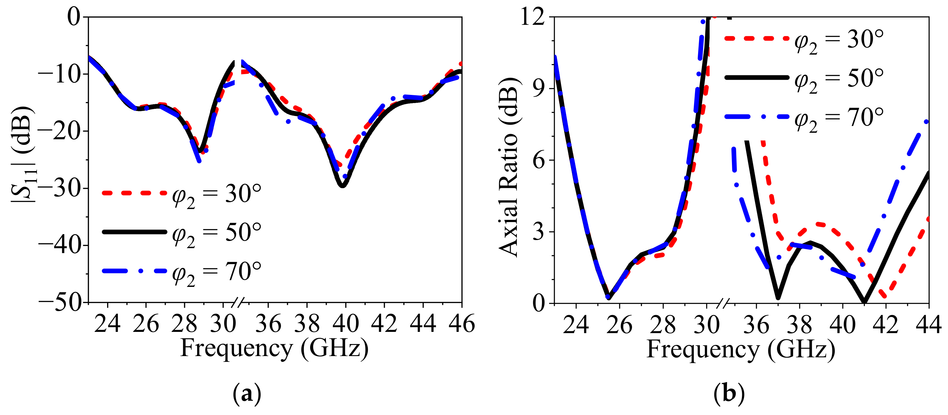
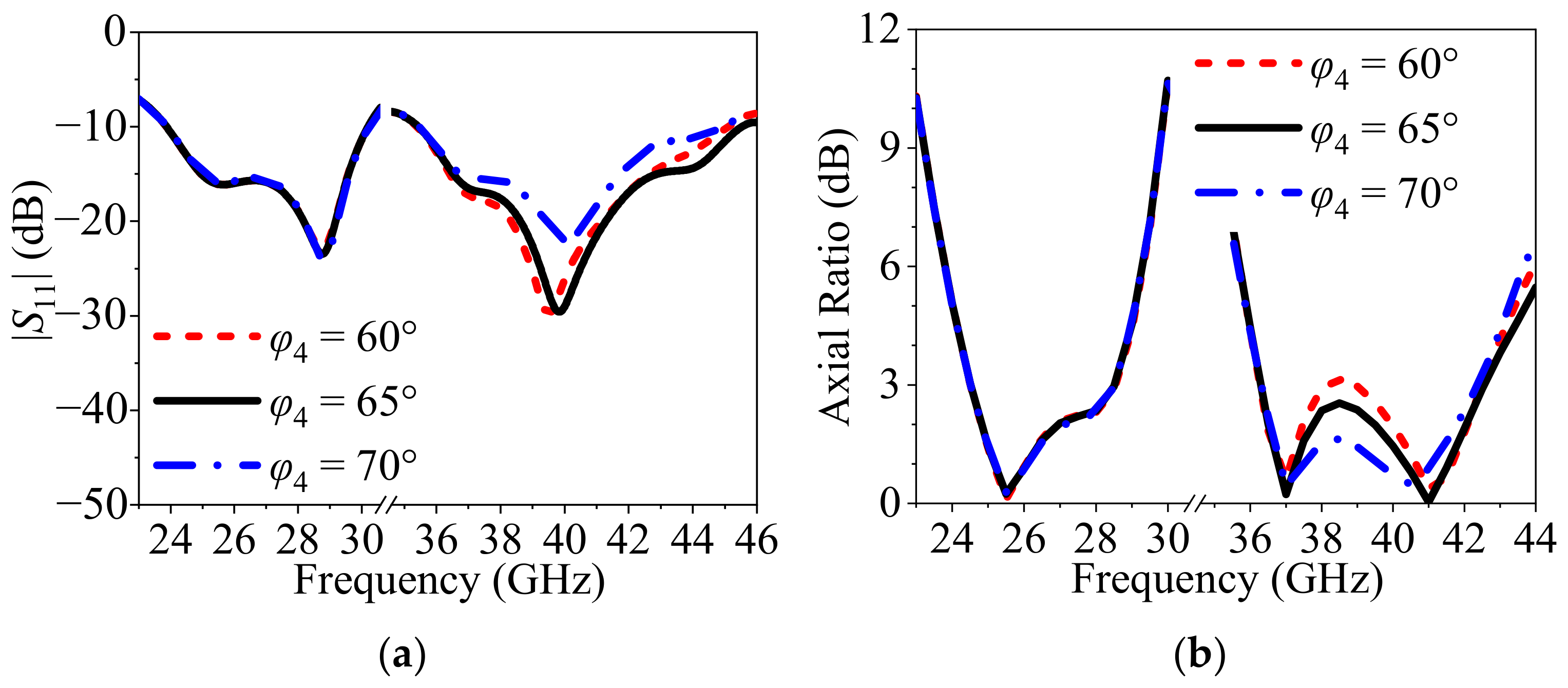
According to the dielectric waveguide model [23] and Marcatili’s approximation technique [24], both the TE δ 11 x and TE 1 δ 1 y modes of the DR resonate at 24.85 GHz. Therefore, the CP resonant mode at 25 GHz is generated by the DR. Similarly, the TE δ 13 x and TE 1 δ 3 y modes of the DR resonate at 37.32 GHz, so at 37 GHz the DRA performs CP characteristics. In addition, Figure 4 depicts the E-field distributions of the DR at 25 GHz and 37 GHz. In Figure 4a, it is clear that the two orthogonal fundamental modes TE δ 11 x and TE 1 δ 1 y are generated at 25 GHz for different phases, which agrees with the theoretical model. As shown in Figure 4b, the TE δ 11 x and TE 1 δ 1 y modes are excited at 37 GHz for different phases. In addition, Figure 4 shows that the E-fields in top views have nearly equal amplitude and rotate in the clockwise direction when t changes from t = 0 to t = T/4 (T is the period). Therefore, the DRA excited by the MCF slot operates in left-hand circular polarization (LHCP) at 25 GHz and 37 GHz.
The concept of hybrid radiation proves that feeding slots can simultaneously act as a feeding structure of the DRA and a dielectric-loaded slot antenna [25]. Figure 5 shows the distributions of the E-fields across the dielectric-loaded MFC slot to figure out the working mechanism of the MCF slot antenna. The vectors E n represent the resultant vectors of local E-fields, where n = 1, 2. The vectors E R is the vector summation of major E-fields vectors E n . At 27.5 GHz, the E-fields are mainly concentrated on Slot 1, as shown in Figure 5a,b. The E 1 and E 2 are primary local vectors of Slot 1. Moreover, E R at t = 0 and t = T/4 are nearly orthogonal in direction and equal in magnitude. Similar results can be drawn at 41 GHz, as shown in Figure 5c,d, except the E-fields are focused on Slot 1 and 3 at t = 0. Furthermore, at both frequencies, the E R rotates in the clockwise direction when t changes from t = 0 to t = T/4, which means the dielectric-loaded MCF slot antenna operates in LHCP. Therefore, resonances of the MCF slots and DR are combined to broaden the operation bandwidth in this work.

4. Parametric Study

To further investigate the proposed DRA, parametric studies are carried out using CST MWS. In this study, only one parameter is varied in the parametric sweep. The radius (r1) of Slot 1, the radian (φ2) of Slot 2 and the radian (φ4) of Slot 3 are investigated. As mentioned above, both DR and the slots’ resonance affect the impedance and AR bandwidth performance.
Figure 6 shows the simulated |S11| and ARs of the proposed DRA at different radius r1. As r1 increases, both the |S11| and AR of the proposed antenna at the lower band shift downwards due to the increase in the electric current path in Slot 1, but the |S11| and AR are barely affected at the upper band. The results indicate that Slot 1 mainly responds to the DRA performance at the lower band.
Figure 7 shows the simulated |S11| and ARs of the proposed dual-band CP DRA at different radian φ2 of Slot 2. Since the increases in φ2 increase the local electric currents path in Slot 2 (see Figure 5c), both the impedance and AR bandwidth at the upper band shift downward when φ2 increases from 30° to 70°.
Figure 8 shows the simulated |S11| and ARs of the proposed DRA at different radian φ4 of Slot 3. Note that the impedance matching for the upper band changes with φ4, but impedance is almost unchanged at the lower band. In addition, the ARs reduce from 38.5 GHz to 40.5 GHz because Slot 3 primarily adjusts the magnitude of E-fields. It is obtained that the lower and upper bands of the proposed DRA can be designed independently, and the design method has great potential for other dual-band CP applications.

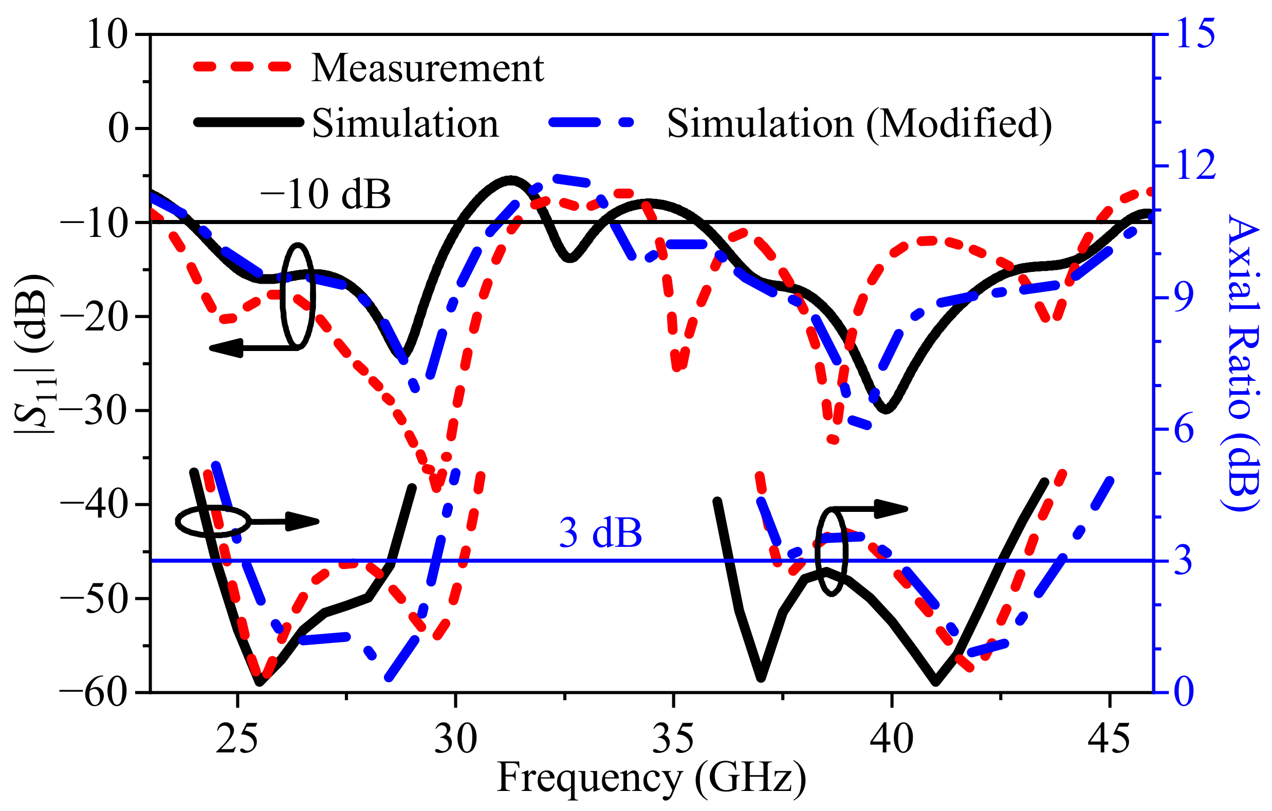
5. Results and Discussion

A proposed DRA is designed, fabricated and measured to verify the performance. The prototype is shown in Figure 9. An end launch connector of 1.85-KFD0830 purchased from Gwave, Inc. (Beijing, China) is applied to feed the microstrip line, and the adhesive of 1406 manufactured by TONSAN, Inc. (Beijing, China) is used to stick the DR to the ground plane.
The simulated and measured reflection coefficients of the proposed dual-band CP DRA are depicted in Figure 10. Since an unexpected air gap between the DR and the ground plane appears in the prototype, we also take the air gap of 0.0015 mm into account (see modified results). The measured impedance bandwidths are 29.3% (23.3–31.3 GHz) and 25.4% (34.36–44.36 GHz), and the measured 3 dB AR bandwidths are 19.8% (24.75–30.18 GHz) and 7.8% (39.85–43.07 GHz). From Figure 10, the modified simulated and measured |S11| and AR results reach good agreements. The discrepancies between the simulation and measurement could be caused by the slight changes in permittivity of the DR and fabrication errors.
The measured and simulated radiation patterns at 27.5 GHz and 40 GHz are shown in Figure 11. The DRA has broadside unidirectional radiation patterns at both frequencies, generating LHCP in the +z-direction. Figure 12 shows measured, simulated and modified gains of the proposed DRA. It also can be seen that the modified results match the measured results. The measured average (peak) gains are 4.98 (5.62) dBic at the lower band and 5.76 (6.74) dBic at the upper band, while the modified simulated average gains are 5.35 dBic at the lower band and 6.18 dBic at the upper band.
A comparison between the proposed dual-band CP DRA and the previously reported mm-wave CP DRAs is summarized in Table 2. It can be seen that the proposed mm-wave DRA has wider overlapping bandwidths than most mm-wave CP DRAs. Moreover, the proposed DRA shows two independently designed bands, which alleviates the design difficulty of dual-band DRAs. In addition, the wideband CP technology used in our work does not need to perform precise micromachining on the DR structure, so it is beneficial to reduce the machining difficulty of mm-wave DRAs. These good performances afford the proposed DRA great development potential in mm-wave communication.
Table 2. Performance comparison of the proposed DRA with previously reported mm-wave DRAs.
Ref. No.* Overlapping Bandwidth @ Center FrequencyPeak Gain (dBic)Independently DesignedWideband CP Technology
[17]10.17% @ 59 GHz10.35-Hybrid of patch antenna and DRA
[18]15.9% @ 59.75 GHz11.43-Sequential rotation feeding array
[19]26.3% @ 23.4 GHz8.15-Modified structure of cylindrical DRA
[20]12.8% @ 22.7 GHz
5% @ 28.1 GHz
LB 1: 5
UB 2: 8
NoModified structure of rectangular DRA
Proposed work19.8% @ 27.5 GHz
7.8% @ 41.5 GHz
LB: 5.62
UB: 6.74
YesHybrid of slot antenna and DRA
* The overlapping bandwidth (bandwidth of |S11|< −10 dB and AR < 3 dB simultaneously). 1 Lower band. 2 Upper band.

6. Conclusions

A dual-band CP DRA fed by an MCF exciting slot has been presented in this paper. The fundamental and higher-order modes of the rectangular DR are successfully excited at the lower and upper bands by the MCF exciting slot. Meanwhile, the dielectric-loaded MCF slot antenna can bring additional resonant modes to improve the operation bandwidths of the DRA. The proposed DRA features a wide CP band and two independently designed bandwidths. Broadside LHCP radiation patterns also have been observed at two frequencies. By fabricating and testing the prototype, the dual-band CP DRA shows a lower CP band of 19.8% and an upper CP band of 7.8%, and the measured peak gains are 5.62 dBic and 6.74 dBic at the lower and upper bands, respectively. Because of the simple DR and compact feeding structure, the proposed dual-band CP DRA is a good candidate for mm-wave 5G applications.

Author Contributions

J.-W.Z.: Conceptualization, supervision and project administration, analysis data, writing and editing manuscript; R.-Z.H.: investigation and design, data analysis and experiment, writing and editing manuscript; C.Z.: data analysis and interpretation, editing manuscript. All authors have read and agreed to the published version of the manuscript.

Funding

This research was supported by the Fundamental Research Funds for the Central Universities (Grant no.: WUT 2021IVB029) and the National Natural Science Foundation of China (Grant no.: 62001338).

Conflicts of Interest

The authors declare no conflict of interest.

References

  1. Rappaport, T.S.; Sun, S.; Mayzus, R.; Zhao, H.; Azar, Y.; Wang, K.; Wong, G.; Schulz, J.K.; Samimi, M.; Gutierrez, F. Millimeter wave mobile communications for 5G cellular: It will work! IEEE Access 2013, 1, 335–349. [Google Scholar] [CrossRef]
  2. Lee, J.; Tejedor, E.; Ranta-Aho, K.; Wang, H.; Lee, K.-T.; Semaan, E.; Mohyeldin, E.; Song, J.; Bergljung, C.; Jung, S. Spectrum for 5G: Global status, challenges, and enabling technologies. IEEE Commun. Mag. 2018, 56, 12–18. [Google Scholar] [CrossRef]
  3. Qiu, H.; Liu, H.; Jia, X.; Jiang, Z.-Y.; Liu, Y.-H.; Xu, J.; Lu, T.; Shao, M.; Ren, T.-L.; Chen, K.J. Compact, flexible, and transparent antennas based on embedded metallic mesh for wearable devices in 5G wireless network. IEEE Trans. Antennas Propag. 2021, 69, 1864–1873. [Google Scholar] [CrossRef]
  4. Jilani, S.F.; Alomainy, A. A multiband millimeter-wave 2-D array based on enhanced franklin antenna for 5G wireless systems. IEEE Antennas Wirel. Propag. Lett. 2017, 16, 2983–2986. [Google Scholar] [CrossRef]
  5. Pan, Y.M.; Qin, X.; Sun, Y.X.; Zheng, S.Y. A simple decoupling method for 5G millimeter-wave MIMO dielectric resonator antennas. IEEE Trans. Antennas Propag. 2019, 67, 2224–2234. [Google Scholar] [CrossRef]
  6. Zhang, Y.; Deng, J.-Y.; Li, M.-J.; Sun, D.; Guo, L.-X. A MIMO dielectric resonator antenna with improved isolation for 5G mm-wave applications. IEEE Antennas Wirel. Propag. Lett. 2019, 18, 747–751. [Google Scholar] [CrossRef]
  7. Bahreini, B.; Oraizi, H.; Noori, N.; Fakhte, S. Design of a circularly polarized parasitic array with slot-coupled DRA with improved gain for the 5G mobile system. IEEE Antennas Wirel. Propag. Lett. 2018, 17, 1802–1806. [Google Scholar] [CrossRef]
  8. Al-Hasan, M.J.; Denidni, T.A.; Sebak, A.R. Millimeter-wave EBG-based aperture-coupled dielectric resonator antenna. IEEE Trans. Antennas Propag. 2013, 61, 4354–4357. [Google Scholar] [CrossRef]
  9. Baldazzi, E.; Al-Rawi, A.; Cicchetti, R.; Smolders, A.B.; Testa, O.; van Coevorden Moreno, C.D.J.; Caratelli, D. A high-gain dielectric resonator antenna with plastic-based conical horn for millimeter-wave applications. IEEE Antennas Wirel. Propag. Lett. 2020, 19, 949–953. [Google Scholar] [CrossRef]
  10. Gong, K.; Hu, X.H. Low-profile substrate integrated dielectric resonator antenna implemented with PCB process. IEEE Antennas Wirel. Propag. Lett. 2014, 13, 1023–1026. [Google Scholar] [CrossRef]
  11. Al-Alem, Y.; Kishk, A.A. Wideband millimeter-wave dielectric resonator antenna with gain enhancement. IEEE Antennas Wirel. Propag. Lett. 2019, 18, 2711–2715. [Google Scholar] [CrossRef]
  12. Chen, Z.; Shen, C.; Liu, H.; Ye, X.; Qi, L.; Yao, Y.; Yu, J.; Chen, X. Millimeter-wave rectangular dielectric resonator antenna array with enlarged DRA dimensions, wideband capability, and high-gain performance. IEEE Trans. Antennas Propag. 2020, 68, 3271–3276. [Google Scholar] [CrossRef]
  13. Girjashankar, P.R.; Upadhyaya, T. Substrate integrated waveguide fed dual band quad-elements rectangular dielectric resonator MIMO antenna for millimeter wave 5G wireless communication systems. AEU Int. J. Electron. Commun. 2021, 137, 153821. [Google Scholar] [CrossRef]
  14. Anab, M.; Khattak, M.I.; Owais, S.M.; Khattak, A.A.; Sultan, A. Design and analysis of millimeter wave dielectric resonator antenna for 5G wireless communication systems. Prog. Electromagn. Res. C 2020, 98, 239–255. [Google Scholar] [CrossRef] [Green Version]
  15. Zhou, Y.; Jiao, Y.; Weng, Z.; Ni, T. A novel single-fed wide dual-band circularly polarized dielectric resonator antenna. IEEE Antennas Wirel. Propag. Lett. 2016, 15, 930–933. [Google Scholar] [CrossRef]
  16. Gupta, A.; Gangwar, R.K. Dual-band circularly polarized aperture coupled rectangular dielectric resonator antenna for wireless applications. IEEE Access 2018, 6, 11388–11396. [Google Scholar] [CrossRef]
  17. Perron, A.; Denidni, T.A.; Sebak, A.R. Circularly polarized microstrip/elliptical dielectric ring resonator antenna for millimeter-wave applications. IEEE Antennas Wirel. Propag. Lett. 2010, 9, 783–786. [Google Scholar] [CrossRef]
  18. Sun, Y.-X.; Leung, K.W. Circularly polarized substrate-integrated cylindrical dielectric resonator antenna array for 60 GHz applications. IEEE Antennas Wirel. Propag. Lett. 2018, 17, 1401–1405. [Google Scholar] [CrossRef]
  19. Yang, M.; Pan, Y.; Sun, Y.; Leung, K. Wideband circularly polarized substrate-integrated embedded dielectric resonator antenna for millimeter-wave applications. IEEE Trans. Antennas Propag. 2020, 68, 1145–1150. [Google Scholar] [CrossRef]
  20. Liu, Y.; Jiao, Y.; Weng, Z.; Zhang, C.; Chen, G. A novel millimeter-wave dual-band circularly polarized dielectric resonator antenna. Int. J. RF Microw. Comput. Aided Eng. 2019, 29, e21871. [Google Scholar] [CrossRef]
  21. Zahra, H.; Awan, W.A.; Ali, W.A.E.; Hussain, N.; Abbas, S.M.; Mukhopadhyay, S. A 28 GHz broadband helical inspired end-fire antenna and its MIMO configuration for 5G pattern diversity applications. Electronics 2021, 10, 405. [Google Scholar] [CrossRef]
  22. Zou, M.; Pan, J. Wideband hybrid circularly polarised rectangular dielectric resonator antenna excited by modified cross-slot. Electron. Lett. 2014, 50, 1123–1124. [Google Scholar] [CrossRef]
  23. Petosa, A. Dielectric Resonator Antenna Handbook; Artech House Antennas and Propagation Library: Boston, MA, USA, 2007. [Google Scholar]
  24. Mongia, R.K. Theoretical and experimental resonant frequencies of rectangular dielectric resonators. IEE Proc. H Microw. Antennas Propag. 1992, 139, 98–104. [Google Scholar] [CrossRef]
  25. Buerkle, A.; Sarabandi, K.; Mosallaei, H. Compact slot and dielectric resonator antenna with dual-resonance, broadband characteristics. IEEE Trans. Antennas Propag. 2005, 53, 1020–1027. [Google Scholar] [CrossRef] [Green Version]
Figure 1. The geometry of proposed dual-bands CP RDRA: (a) Perspective view of the entire structure; (b) Bottom view of the end of the microstrip line; (c) Top view of the MCF slot.
Electronics 11 01761 g001
Figure 2. Configurations of three reference antennas and the proposed antenna: (a) Antenna 1: the DRA fed by Slot 1; (b) Antenna 2: the DRA fed by Slot 2; (c) Antenna 3: the DRA fed by Slot 1 and 2; (d) Antenna 4: the proposed antenna.
Electronics 11 01761 g002
Figure 3. Simulated results of the four types of antennas: (a) Reflection coefficients; (b) ARs toward (θ = 0°; φ = 0°).
Electronics 11 01761 g003
Figure 4. The distributions of the E-fields inside the DR: (a) 25 GHz at t = 0 and t = T/4; (b) 37 GHz at t = 0 and t = T/4.
Electronics 11 01761 g004
Figure 5. The distributions of the E-fields across the dielectric-loaded MCF slot: (a) 27.5 GHz at t = 0; (b) 27.5 GHz at t = T/4; (c) 41 GHz at t = 0; (d) 41 GHz at t = T/4.
Electronics 11 01761 g005
Figure 6. Simulated results of the dual-band CP DRA at different radius r1 of Slot 1: (a) Reflection coefficients; (b) ARs.
Electronics 11 01761 g006
Figure 7. Simulated results of the dual-band CP DRA at different radian φ2 of Slot 2: (a) Reflection coefficients; (b) ARs.
Electronics 11 01761 g007
Figure 8. Simulated results of the dual-band CP DRA at different radian φ4 of Slot 3: (a) Reflection coefficients; (b) ARs.
Electronics 11 01761 g008
Figure 9. Photographs of the fabricated prototype: (a) Top view; (b) Bottom view.
Electronics 11 01761 g009
Figure 10. Simulated and measured reflection coefficients and broadside ARs of the proposed dual-band CP DRA.
Electronics 11 01761 g010
Figure 11. Simulated and measured radiation patterns of the proposed DRA: (a) Radiation patterns at 27.5 GHz; (b) Radiation patterns at 40 GHz.
Electronics 11 01761 g011aElectronics 11 01761 g011b
Figure 12. Simulated and measured gains of the proposed DRA.
Electronics 11 01761 g012
Table 1. Geometric parameters of the proposed DRA.
ParametersValuesParametersValuesParametersValues
a2.6 mmh3 mmt0.254 mm
Lex5 mmLg30 mmwm10.74 mm
wm21.34 mmlm11 mmlm21.2 mm
φ150°φ250°φ315°
φ465°ls10.9 mmls20.15 mm
ws10.2 mmws20.05 mmws30.1 mm
ws40.1 mmr10.7 mmr20.6 mm
r30.25 mmr41.35 mmwt0.49 mm
lt0.6 mm
Publisher’s Note: MDPI stays neutral with regard to jurisdictional claims in published maps and institutional affiliations.

